

Page 1
AUTOMATIC
LOCK
STITCH
POCKET
WELTING
SEWING
MACHINE
INSTRUCTION
FOR
-
-------------l
FLAP
ATTACHMENT
[
MANUAL
..__.______
_ ]
BAS-600
BAS-601
0 ' •
~___I
_
___;
Page 2
Contents
1 • SPECIFICATIONS
2.
CONTROL
3.
INSTALLATION
• Table
1
• Treadle installation · · · · · · · · · · · · · · · · • · · · · · · · · · · · · · · · ·· · · • · · · • • · • · · · • · • · · • · · · · · · ·· · · · · · · · · · · · · · · · · · · · · 6
2
3
• Spool stand installation · · · · · · • · · · · · · · · · · · · · · · · · · · · · · · • · · · · · · · · · · · · · · · · · · · · · · · · · · · • · · · · · · · · · · · · · · · · 6
• Material holder installation .... · · · · • · · · · ...... · · · · · · · · · · · · · · · · · · · · · · · · · · · · .. · • · · · · · · · · · · · .. · • · • • 6
4
5 . Bar
6
• Pickup type stacker installation .... · .. · .... · · · .. · .. · · · · .. ·
• Air pressure adjustment·· ..
7
4.
LUBRICATION··········...................................................................................
< Adding oil > ··
< Regular lubrication > · · · .. · · · · · .. · · · .. · .. · · · • • ...... · .... · · · .... · · · · · .. · · · .. · .. · · · · · · · · .. · · · · · · · · · · 1 0
5.
CORRECT OPERATION
< Winding the bobbin thread >
< Threading the
< Threading the bobbin thread > .... ·
< Holding the
6.
TREADLE AND START SWITCH
< Treadle operation >
PANEL DESCRIPTION
set-up··························································································
type
stacker installation · · · · · • · · • · · · · · · · • · · · • • • · · · · · · • · · · · · · • · · · · • · • • · · · · · • · • • · • · · •
··············•·••·••·····························•····················•··•··•·•••·••·•
·····•·····•·•·······
··•···•····································••····•···················•··········•··•······
.................
needle
needle
·············
· ................................................. ··•·
..............................................................................
.....................................................
thread >
and bobbin threads >
DESCRIPTION................................................
.................................................................................
.........
..........
.. ··· .. ·· ..
................
············•·······•······•••····•··········
......
· .... · · · .... · • · .... · .. · .... · · · 8
·····
.. · .... ·· .. ··· .. · .... •·•···•· .. ·•·• .. ····• 9
......
·•··•···••••·••·
......
...................................
· .. · .. • · · · .. · ... · • · •
..........
..............
.............................. · 14
...........................
·········
·•
• .. · • · • · 7
2
6
6
9
··· · 9
11
11
12
15
16
16
< Setting the material > · · .. · · · • • · · .. · .. · .. · · · · · ... · · · .. · · · · · · .... · · · • · • · · • · • • ·
7.
ADJUSTING THE MARKING LIGHT
8.
PROGRAMMING (Entering a standard sewing program)
9 • PROGRAMMING (Entering a flap sewing program) ..
10.
PROGRAMMING (Entering a cycle sewing program)
<
Checking
11.
PROGRAM CONFIRMATION
12. SEWING
< Setting the bobbin counter > .. • · · • · · · · · · · · · .. · .. · .. · .. · · · · .... · .. · .. · · · ·
<
Checking
< Clearing the
< Stitch tension > · · • · · .. · · · · • · · .. · · .. · · · · · · .. • • · · · .. · · · · .. · .. · · · ...... · · · · · · • · · .... · · · · · • · · · · · · .. · · · · · ·
13.
CENTER KNIFE POSITION ADJUSTMENT
14.
CORNER KNIFE POSITION ADJUSTMENT
15.
< FLAP SENSOR SENSITIVITY ADJUSTMENT (BAS-601) >
16.
TROUBLEooooooooooooooooooooooooooooooooooooooooooooooooooooooooooooooooooooooooooooooooooooooooooooooooooo
<UPPER
< BOBBIN EMPTY indicator lights >
< PROGRAMMING ERROR indicator
<EMERGENCY
17. OPERATING THE STACKER DURING CYCLE SEWING
the sewing cycle > · .... · .... · · .. · · ...... · .... · · · ... · · · .. · · · · ...... · · · .. · · · .. · · · .. · · · .. ·
........................................................................
...................................................................................................
the number of
work
THREAD BREAKAGE indicator
STOP>..............................................................................
work
piece
counter display > ..... ...
...............................................................
....................................
.....................
.......................................
pieces
> · .. · · .... · .. ·
..............
......................................................
lights>
............................................................
lights>
............ · ........
..............
..........................
.............................................
................................................
....................................
••
• · .. • • · •
••
• · •
·•
...................
·•
· • · · • · • • · • • · · .... · · · · · ·
· .. · .. ·
........
.........
....................
..............
...........................
· • • · · •
·....
17
18
19
20
22
23
24
25
26
26
26
·.
27
28
29
30
32
32
32
33
33
34
Page 3
18. STANDARD ADJUSTMENTS
········································································
< Needle installation > · ·•· ············ ····· ····· ········· ··· ··· ········· ··············· ·· ·········· ·
< Upper and lower shaft timing adjustment >
< Needle and rotary hook timing adjustment >
[Needle
[Rotary hook to needle plate gap] ·· ······ ······ ············
[Needle
fRotary hook and bobbin case opener gapJ
19. CARRIAGE FEED ADJUSTMENT
to rotary hook point gap]
bar lift stroke and needle bar height] ······ ········· ····· ·····•···· ····· ·•·•··· ···
..................................................................
............................................................
···················································
········
·········
·······•·······························•········
·····
··········
..................................
···
··
...........
35
35
35
35
35
36
36
36
37
< Parallel adjustment of needle and carriage feed > · · · · · · · · · · · · · · • · · · · · · · · · · · · · · • · · · · · · · · ·
< Carriage feed angle adjustment > · · • · · · · · · · · · · · · · · · · · · · · · · · · · · · · · · · · · · · · · · · · · · · · · · · · · · · · · · .. · .. ·
< Carriage feed height adjustment > · · · · · · · · · · · · · · · · · · · · · · · · · · · · · · · · · · · · · · · · · · · · · • · · · · · · · · · · · · · ·
< Folding plate position adjustment > · · · · · · · · · · · · · · · · · · · · · · · · · · · · · · · · · · · • · • · ·· · · · · · · · · · · · • · ·· • · · ·
< Binder position adjustment > · · · ·· · · · · · · · · · · · · · ·· · · · · · · · · · · · · · · · · · · · · · · · · · · · · ·· · · · · · · · · · · · · ··· · · · ·
20. SENSOR ADJUSTMENT
< Needle thread knife sensor adjustment > · · · · · · · · · · · · · · · · · · · · · · · · · · · · · ·
< Corner knife
21. STACKER
adjustment>
ADJUSTMENT··············································································
··············································································
··
· · · · · · · · · · · · ·
·······················
···············•················•················
·· · ·..
< Bar stacker > · · · · · · · · · · · · · · · · · · · · · · · · · · · · · · · · · · · · · · · · · · · · · · · · · · · · · · · · · · · · · · · · · · · · · · · · • · · · · · · · · · · · · · · • · ·
< Pickup stacker > · · · · · · · · · · · · · · · · · · · · · · · · · · · · · · · · · · · · · · · · · · · · · · · · · · · · · · · · · · · · · · · · · · · · · · ·
22. KNIFE
REPLACEMENT·················································································
··
· · · · ·
··
· · · ·
< Corner knife replacement > · · · · · · · · · · · · · · · · · · · · · · · · · · · · · · · · · · · · · · · · · · · · • · · · · · · • · · · · · · · · · · · · · · · · ·
< Needle thread trimmer knife replacement > ··········· ···· ·············· ······ ···•····· ····
< Bobbin thread knife replacement > · · · · · · · · · · · · · · · · · · · · · · · · · · · · · · · · · · · · · · • · · · · · · · · · · · • · • · · · · · · ·
< Center knife replacement > · · · · · · · · · · · · · · · · · · · · · · · · · · · · · · · · · · · · · · · · · • · · · · • · · · · · · · · · · · · · · · · · · • · · ·
< Fixed knife replacement > · · · · · · · · · · · · · · · · · · · · · · · · · · · · · · · · · · · · · · · · · · · · · · · · · · · · · · · · · · · · · · · · · · · · · · · ·
23. DOUBLE WELTING--. SINGLE WELTING (DEFORMED WELTING) REPLACEMEMT
< Changing from double to single welting > · · · · · · · · · · · · · · · · · · · • · · · · · · · · · · · · · · · · · • ·· · · · · · · · · · · ·
< Changing from double to deformed welting > · · · · · · · · · · · · · · · · · · · · · · · · · · · · · · · · · · · ·· · · • · · · · · · · ·
24. ERROR MESSAGES ···
25.
MAIN
CIRCUIT BOARD DIP SWITCH
···················
···························································
DESCRIPTIONs.......................................
···
37
37
38
38
39
40
40
41
42
42
43
44
44
45
46
47
47
48
48
48
49
50
26. MEMORY INITIALIZATION
27.
TROUBLESHOOTING
···········································································
·················•·······························································
52
53
Page 4
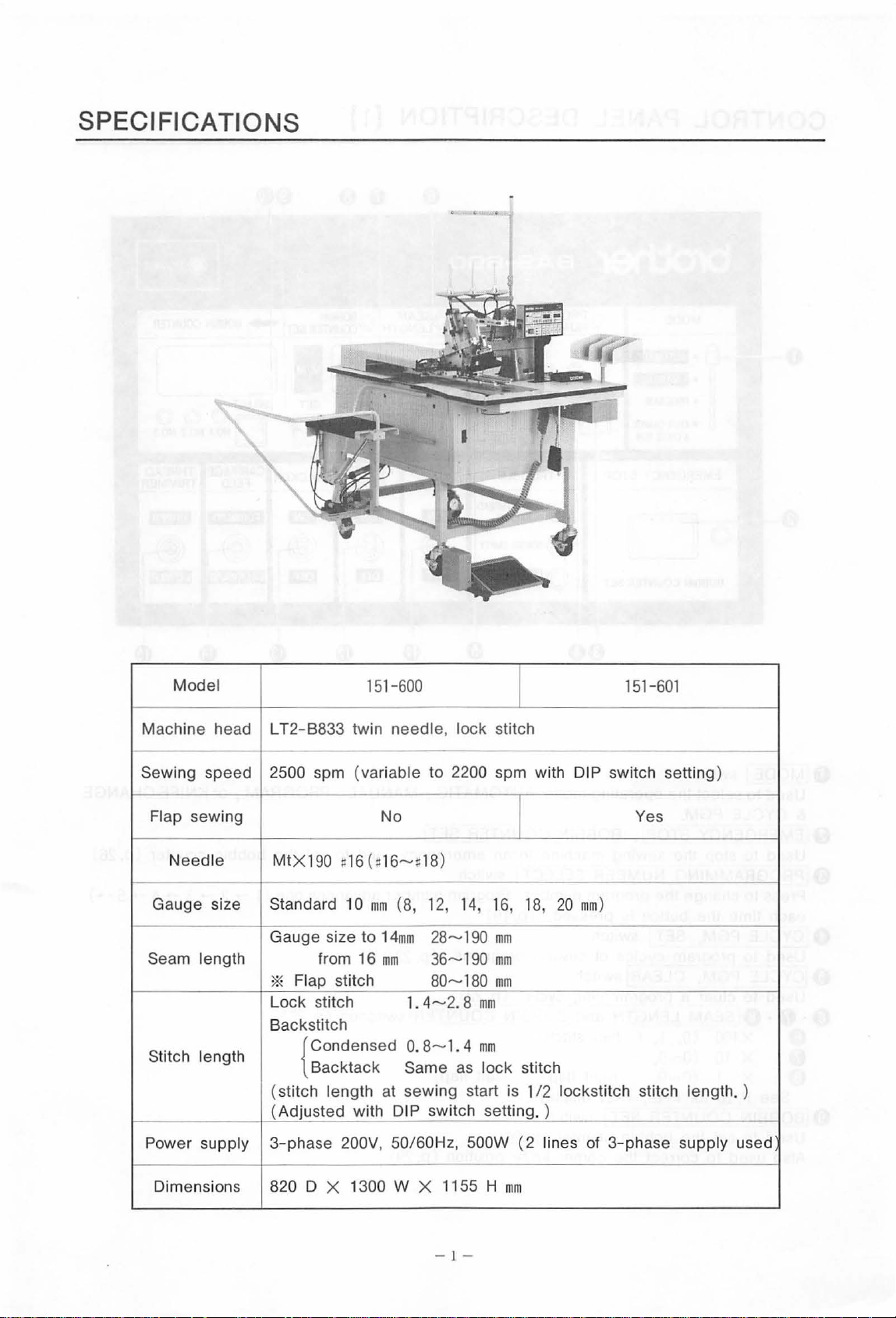
SPECIFICATIONS
Model
Machine he ad LT2
Sewing
Flap sewing No
Gauge size Standard 10
speed
Needle
-·
Seam length from 16
-B833
2500 spm
MtX190
Gauge size to
twin needle,
(varia
~
16
* Flap stitch
Lock
stitch
Backstitch
Stitch length
{ Condensed 0. 8--1 . 4
Backtack
(s
titch length
(Adjusted with DIP switch
151-600
ble
to 2200 spm with
U16--#18
mm
14mm
mm
at
)
(8,
12,
28--190
36--190
80--180
1.
4--2.8
Same
sewing start is 1
I
lock stitch
I
14, 16,
as
18,
mm
mm
mm
mm
mm
lock
stitch
setting.)
15
1-601
DIP switch setting )
Yes
20 mm)
/2
lockstitch stitch length. )
Power supply
Dimensions 820 D X 1300 W X 1155 H
3-phase
200V, 50/60Hz, 500W ( 2 lines of
mm
- 1 -
3-phase
supply used
Page 5
CONTROL
PANEL DESCRIPTION (1]
©
BOBBIN
EMPTY
©~RAMMING
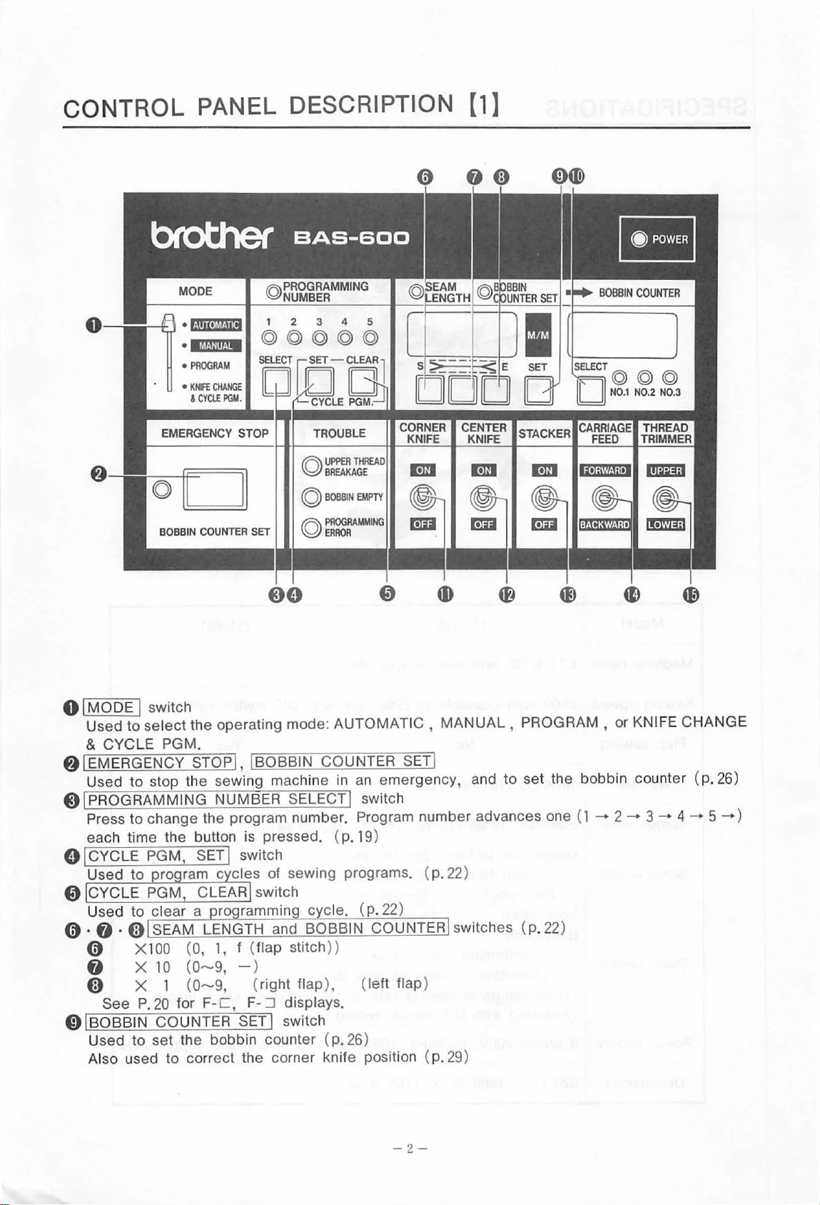
O IMODE I switch
to select
Used
& CYCLE PGM.
f)
I EMERGENCY STOP I, I BOBBIN COUNTER SET!
Used
Q IPROGRAMMING NUMBER SELECT ! switch
each time the button
O ICYCLE PGM, SET I switch
Press
Used
to
to
change the program number. Program number advance s one (1 -+
to
the operating mode:
stop the sewing machine in
is
pressed. ( p.
ro ram c cles of sewing programs. ( p. 22)
AUTOMATIC,
an emerge
19
)
0 CYCLE PGM CLEAR switch
to
clear
Used
0 · 0 ·
«;)
0 X1
0 X
«;)
See
01BOBBIN
to
Used
Also used
a ro ram min c cle. (
SEAM LENGTH and BOBBIN
00
(0, 1, f (flap stitch
10 (0-9,
X 1 (
P.
20
for
COUNTER
set
the bobbin counter (
to
0-9,
correct the corner knife position ( p. 29)
F-C,
- )
(right flap
F-
:::::J
SET!
displays.
switch
))
),
p.
26)
p.
22)
COUNT
(left flap)
MANUAL,
ncy, and to set the bobbin counter (p. 26)
ER
switches (p. 22)
PROGRAM , or KNIFE CHANGE
2-+
3-+
4-+
5-+
)
-2-
Page 6
•
t!11UeJM.)i[j
•l&f-HIINM
•
PROGRAM
•
KNIFE
CHANGE
&
CYCI.f
PGM.
EMERGENCY STOP
A
UPPER
BOBBIN
THREAD
EMPTY
~BREAKAGE
(Q)
©~RAMMING
~!BOBBIN
Press to
-
2-
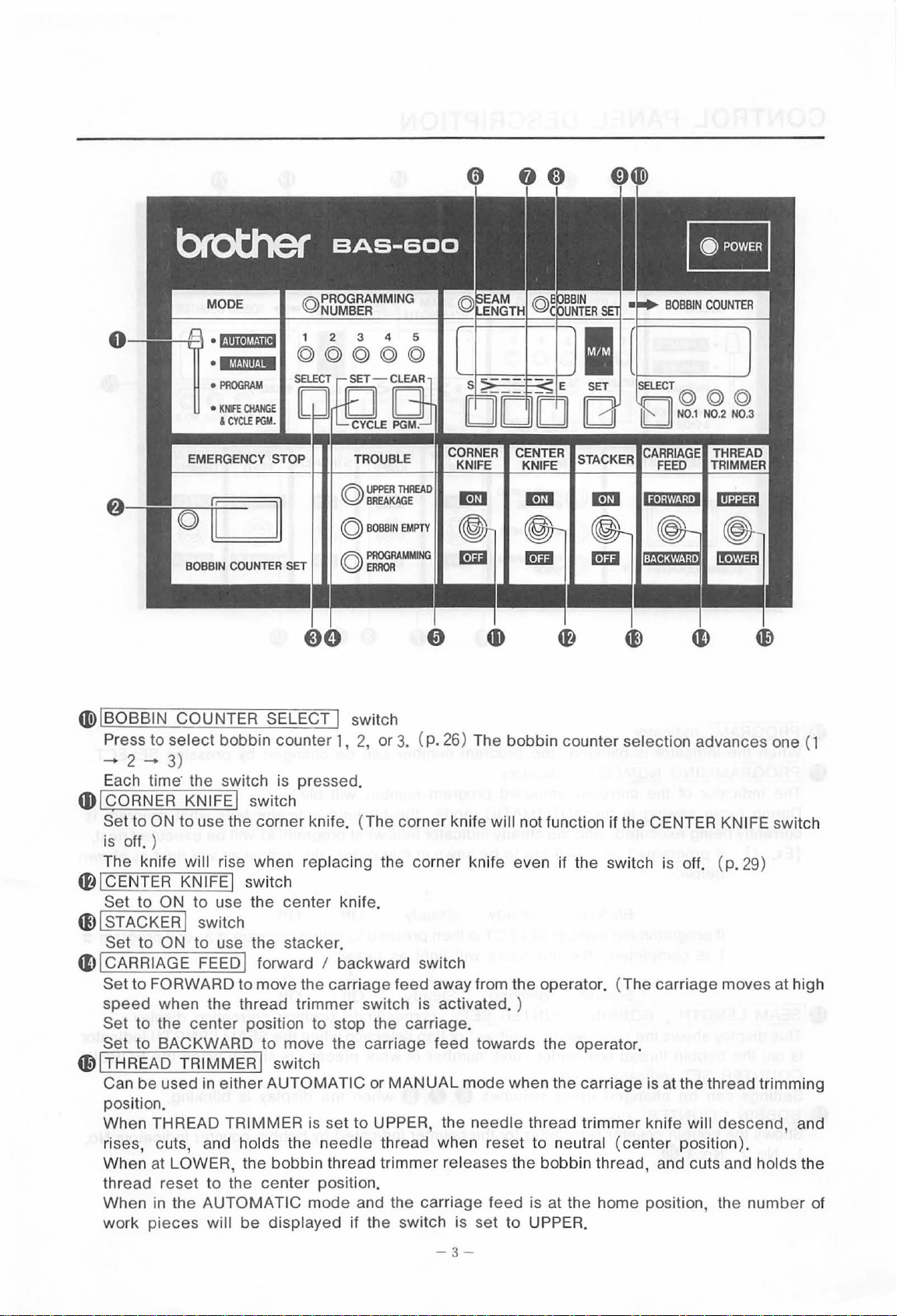
COUNTER SELECT I switch
select
bobbin counter 1, 2, or 3. ( p. 26) The bobbin counter selection advances one ( 1
3)
Each time· the switch is pressed.
Q}ICORNER
KNIFE! switch
Set to ON to use the corner knife. (The corner knife will not function if the CENTER KNIFE switch
is
off. )
Th
e knife will rise when replacing the corner knife even if the switch is off. ( p. 29)
~!CENTER
Set to ON
41)
I STACKER I switch
Set to ON
41)
I CARRIAGE FEED I forward I backward switch
Set to FORWARD
speed
Set
Set to BACKWARD
~~THREAD
Can be used in either AUTOMATIC or
KNIFEj switch
to
use
the
center
to
use the stacker.
to
move the carriage feed away from the operator. (The carriage moves at high
knife.
when the thread trimmer switch is activated. )
to
the
center
position to stop the carriage.
to
move the carriage
feed
TRIMMER! switch
MANUAL
mode when the carriage
towards the operator.
is
at the thread trimming
position.
When THREAD
ri
ses, cuts, and holds the
When at
LOWER, the bobbin thread trimmer releases the bobbin thread, and cuts and holds the
thread reset
When in the
pieces
work
TRIMMER is set
to
the
center
AUTOMATIC mode and the carriage
will
be
displayed if the switch is set to UPPER.
to
needle
position.
UPPER, the
needle
thread when reset
feed
thread trimm
to
neutral
er
knife will
(center
descend,
position).
is at the home position, the
number
and
of
-3
-
Page 7
CONTROL
PANEL DESCRIPTION
•
t!jiiUJl&littl
·IM,UIIHM
•
PROGRAM
•
KNIFE
~
EMERGENCY STOP TROUBLE
4D
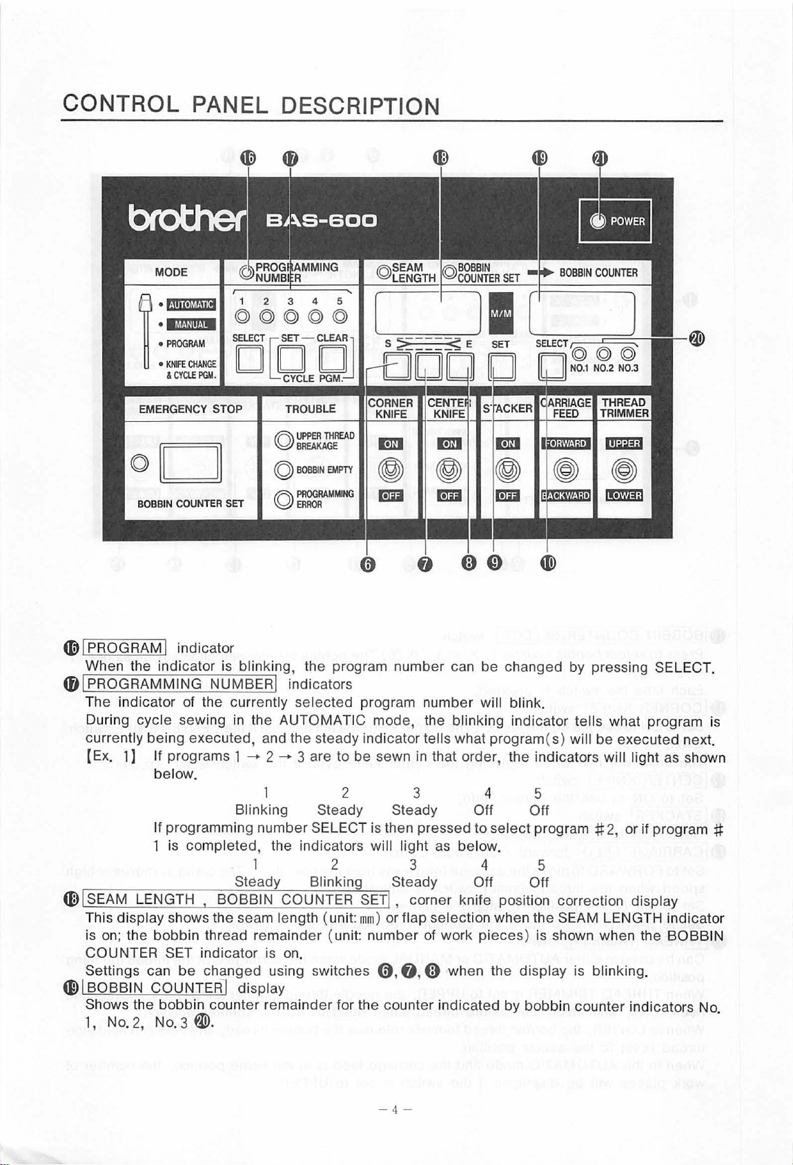
I PROGRAM I indicator
When the indicator is blinking, the program numb
4f#
J PROGRAMMING NUMBERJ indi cators
Th
e indicator of the currently sel
During cycle sewing in the AUTOMATIC mode, the blinking indicator tells what program is
currently being executed, and the steady indicator tells what program
[E
x.
1] If programs 1 -+
4E)
I SEAM LENGTH , BOBBIN COUNTER SETI , corner knife position correction display
This display shows the seam length (unit:
is on; the
COUNT
Settings can
4D
I BOBB IN CO UNT
Shows
1, N
ER
the bobbin counter remainder for the counter ind icated by bobbin counter indicators No.
o.2,
CHANGE
&
CYClE
be
low.
programming number SELECT is then pressed to sel
If
1 is completed, the indicators will light as below.
bobb
in thread remaind
SET indicator is on.
be
No. 3 W.
1 2 3 4 5
©©©©©
PGM.
DCOJOJ
fR\
UPPER
~BREAKAGE
©
2-+
Blinking Steady Steady Off Off
1 2 3 4 5
Steady Blinking Steady Off Off
chang
ed
using switches 0 ,
ER
I display
THREAD
BOBBIN
EMPTY
ected
3 are
er (unit:
er
can
program numb
to
be sew n in that order, the indicators will light as shown
2 3 4 5
mm)
or fl ap selection when the SEAM LEN GTH indicator
number
0,
er
of
work
0 when the display is blinking .
be
changed by pressing SELECT.
will blin
pieces ) is shown when the BOBBIN
k.
(s) will
ect
program #
be executed next.
2,
or if program #
- 4 -
Page 8
.
\.-
~~-
.:-:.;.-
---.
---
~
0
~
1-1--ll--~
1--L--'t:::::::::~
~-
0
>.-=-=<
iJ---~i
600
~
:
~---
~
---
:
~::
~~
---
-
~
-~-
0 9 9 0
- --
~~
~~
601
--
-n--
--
~
~
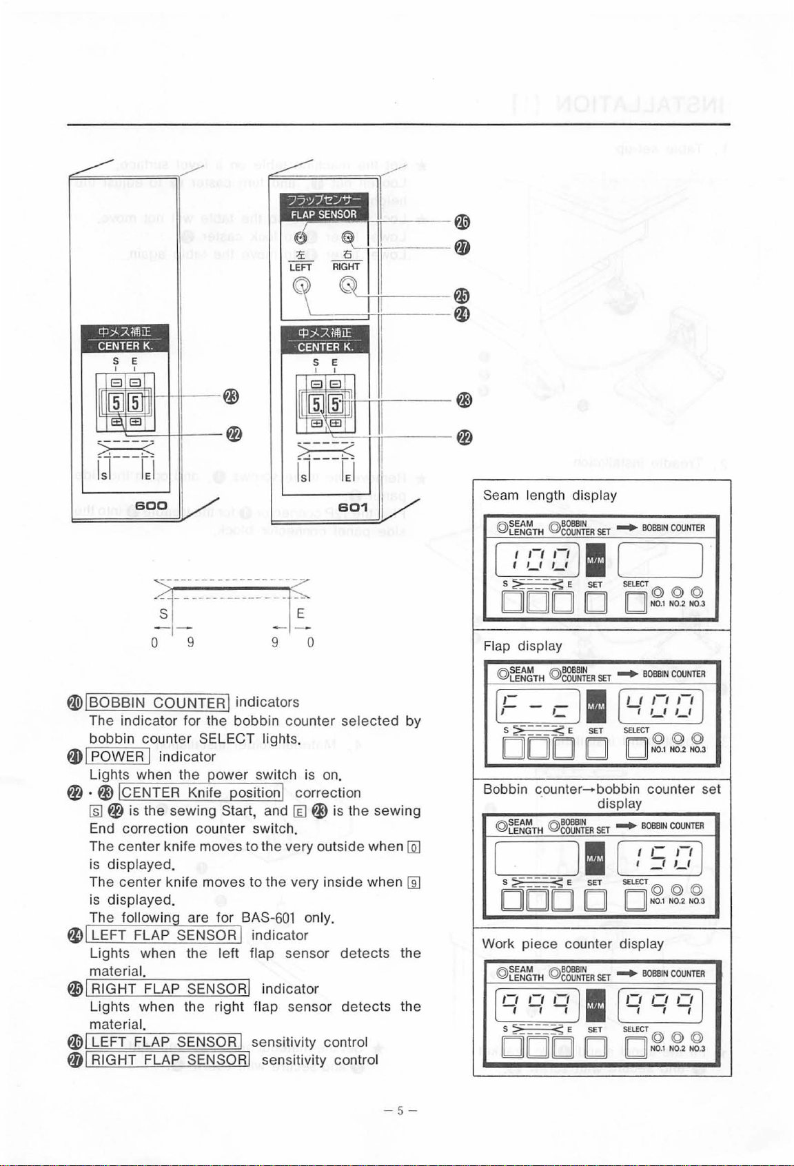
Seam length display
@
~~~TH @g~~
I
,-,
,
,_,
[
S
;? ____
_
DODD
Flap displ
@
ay
t~~~TH
@
,-,
11
,_,
0:;:
E
SET
gg:~
SET
SET
-+
BOBBIN COUNTER
(
SELECT
D@@
N0.1 N0.2 N0.3
-+
BOBBIN COUNTER
)'
@
W IBOBBIN COUNTER! indicators
Th
e indicator for the bobbin counter
bobbin
tDI
POWER I indi cator
Lights when the ower switch is
0 ·
~
~
End correcti
The center knife moves to the very outside when
is displayed.
The center knife moves
is displayed.
The followin are for BAS
~
LEFT FLAP SENSOR indicator
Lights when
material.
~~RIGHT
Lights when the right
material.
~~
LEFT FLAP SENSOR I sensitivity control
01
RI
co
unt
er SELECT lights.
CENTER Knife osition correction
0
is
the sewing Start, and [ill ~ is the sewing
on
count
er
switc
h.
to
the very inside when
-601 on
th
e l
eft
flap sensor
FLAP SENSOR! indicator
flap sensor detects the
GHT FLAP SENSOR! se nsitivity control
selec
on
.
ly.
detects
ted by
[ill
Eru
the
- -l I f u
(
:-
S ;? _
DODD
Bobbin
@
t~~~TH
[
S ;?
DODD
Work piece counter display
@
SEAM @80681N
LEN
[
'7
S
DODD
I_
___
_
~
E
counter-bobbin
@
~JeR
_____
GTH
'i
;? _____
ll
<:;:
E
COUNTER
I:
ll
~
E
SET
SET
SET
SE
displ
SET
T
I 1_1 1_1
SElECT
D@@
counter set
ay
-+
BOBBIN
I
I
_t
(
SELECT
D@@
N0
-+
BOBBIN
(
'7
SELEC
T@
IDI
N0
,-,-,
N0.1 N0.2 N0.3
,-
,-:
l
@
COUNTER
1-1 )
1_1
@
.1 N0.2 N0.3
COUNTER
'7
)
@@
.1 N0.2 N0.3
-
5-
Page 9
INSTALLATION
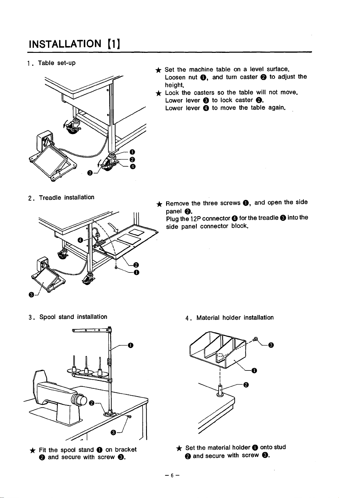
1 . Table set-up
2
• Treadle installation
[1]
* Set the machine table
0,
Loosen nut
height.
and turn caster
on
a level surface.
f)
to adjust the
* Lock the casters so the table will not move.
Lower
Lower lever 8 to move the table again.
lever 0 to lock caster
* Remove the three screws
panel
Plug the
side
f).
12P
connector 8 for the treadle 0 into the
panel connector block.
f).
0,
and open the side
3.
Spool stand installation
* Fit the spool stand 0
f)
and secure with screw
on
bracket
0.
4 • Material holder installation
* Set the material holder 0 onto stud
t)
and secure with screw
-6-
0.
Page 10
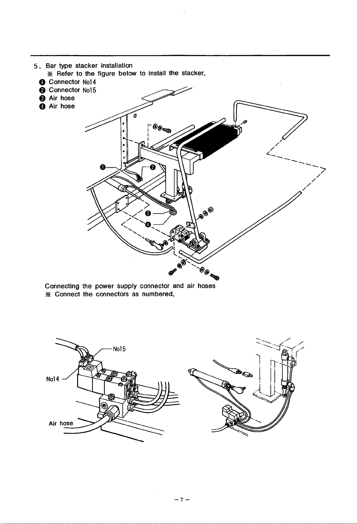
5 • Bar type stacker installation
* Refer to the figure below to install the stacker.
0 Connector
8 Connector
0 Air hose ·
8 Air hose
No14
No
15
4(-
/
/
/
--
---
/
/
-"""->
/
/
/
Connecting the power supply connector and air hoses
* Connect the connectors
Air
hose
as
numbered.
-7-
Page 11
INSTALLATION [2]
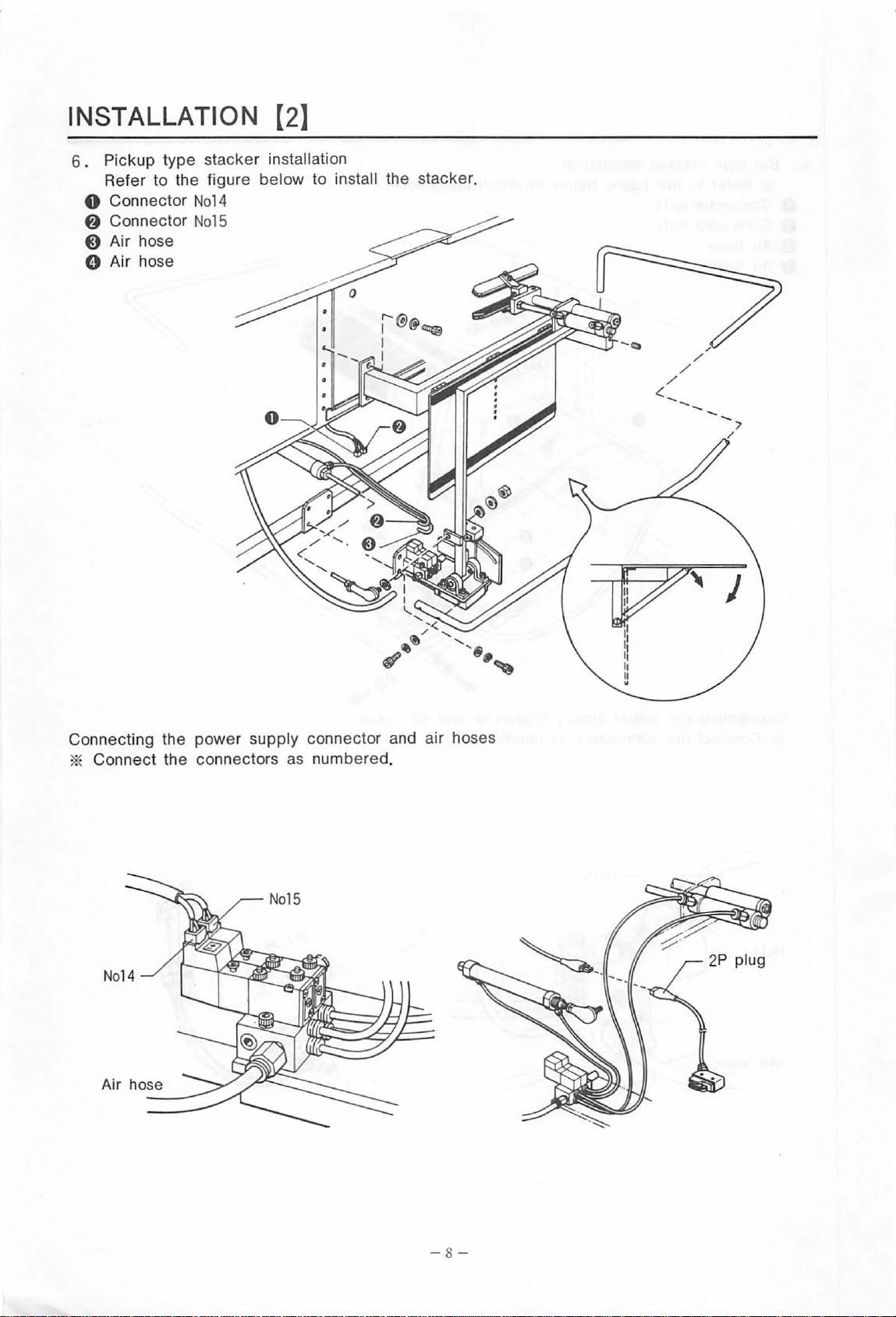
6.
Pickup type stacker installation
Refer to the figure
0 Connector
f)
Connector
No14
No15
0 Air hose
0 Air hose
below
to install the stacker.
/
.::::
__
/
/
/
--.
Connecti ng the power supply conn
*
Co
nnect the connectors as numbered.
15
No
Air hose
ector
and air hoses
-8-
Page 12
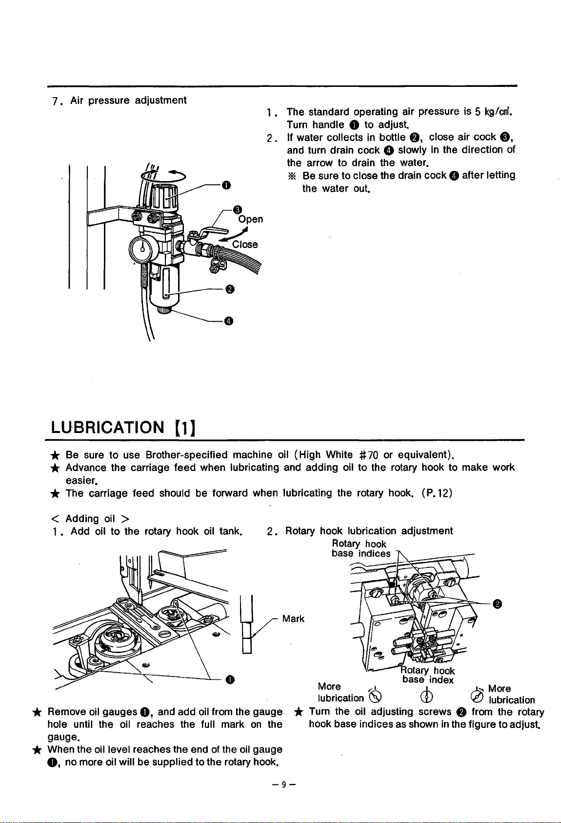
7 • Air pressure adjustment
1 • The standard operating air pressure is 5
Turn handle 0 to adjust.
2 • If water collects
and turn drain cock 8 slowly
the arrow to drain the water.
in
bottle
8,
close air cock
in
the direction of
* Be sure to close the drain cock 8 after letting
the water out.
kg/em.
0,
LU·BRICATION
* Be sure to use Brother-specified machine oil (High White #
[1]
70
or equivalent).
* Advance the carriage feed when lubricating and adding oil to the rotary hook to make work
easier.
* The carriage feed should be forward when lubricating the rotary hook. (
P.
12)
< Adding oil >
1 • Add oil to the rotary hook oil tank.
2 • Rotary hook lubrication adjustment
Rotary
base
hook
indices
YMark
* Remove oil gauges
hole until the oil reaches the
gauge.
0,
and add oil from the gauge
full mark
on
the
* When the oil level reaches the end of the oil gauge
0,
no more oil will be supplied to the rotary hook.
More
lubrication
,::1 •
(S)
CD
* Turn the oil adjusting screws 8 from the rotary
as
hook base indices
shown
in
~More
\0
the figure to adjust.
lubrication
-9-
Page 13
LUBRICATION (2]
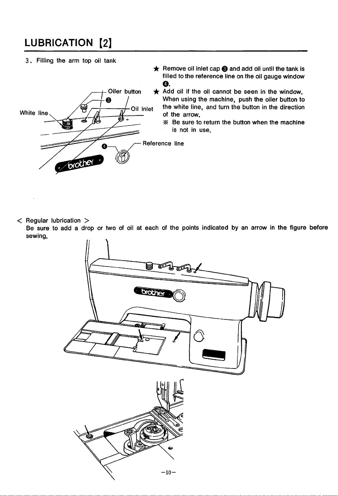
3 • Filling the arm top oil tank
* Remove oil inlet cap 8 and add oil until the tank
filled to the reference line
e.
* Add oil if the oil cannot be seen
When using the machine, push the
line,
and
the white
of the arrow.
* Be sure to return the button when the machine
is
not
in
use.
turn the button
on
the oil gauge window
in
the window.
oiler button to
in
the direction
is
< Regular lubrication >
Be sure to add a drop or two
sewing.
of
oil at each of the points indicated by
an
arrow
in
the figure before
Page 14
CORRECT OPERATION
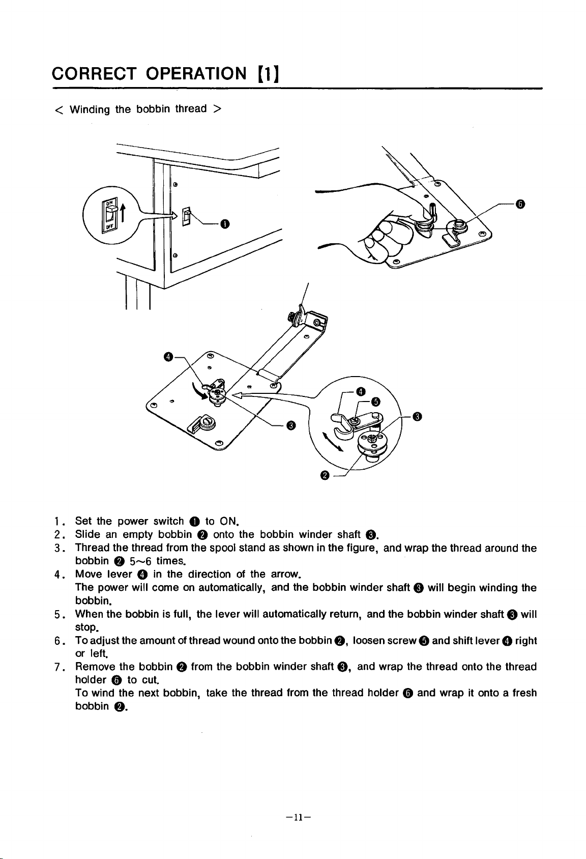
< Winding the bobbin thread >
(1]
1 • Set the power switch 0 to ON.
2.
Slide
3.
Thread the thread from the spool stand
bobbin
4.
Move lever 8
The power will come
bobbin.
5.
When the bobbin is full, the lever will automatically return, and the bobbin winder shaft 0 will
stop.
6.
To adjust the amount of thread wound onto the bobbin
or left.
7 . Remove the bobbin
holder
To wind the next bobbin, take the thread from the thread holder
bobbin
an
empty bobbin
f)
5--6
in
0 to cut.
f).
f)
times.
the direction
on
automatically, and the bobbin winder shaft 0 will begin winding the
f)
from the bobbin winder shaft
onto the bobbin winder shaft
as
of
the arrow.
shown
in
the figure, and wrap the thread around the
f),
loosen screw 8 and shift lever 8 right
0,
-11-
8.
and wrap the thread onto the thread
0 and wrap it onto a fresh
Page 15
CORRECT OPERATION
[2]
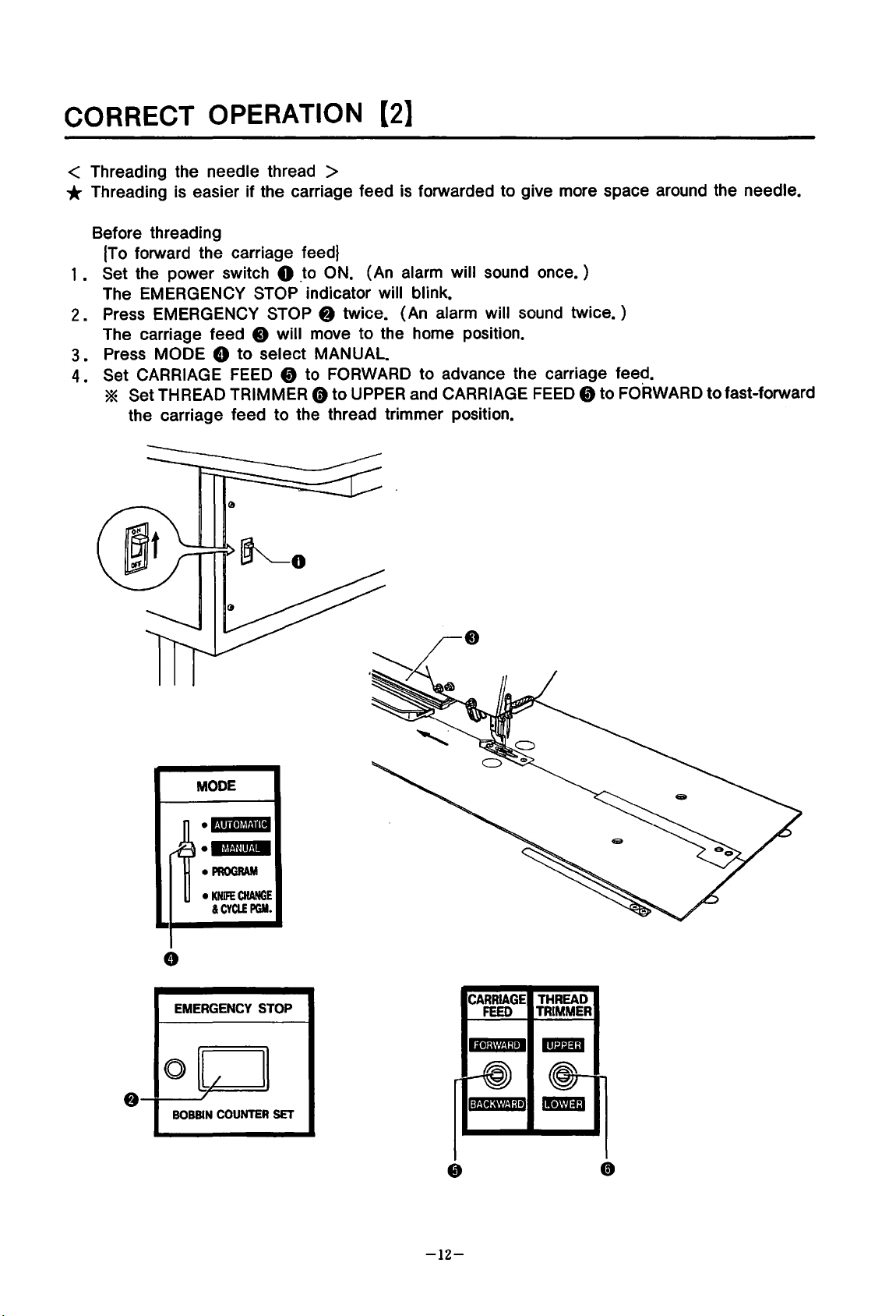
< Threading the needle thread >
* Threading is easier if the carriage feed is forwarded to give more space around the needle.
Before threading
(To
forward the carriage
1 • Set the power switch 0
The EMERGENCY STOP indicator will blink.
2.
Press EMERGENCY STOP 8 twice. (An alarm will sound twice. )
The carriage feed
3.
Press MODE 8 to select MANUAL.
4.
Set CARRIAGE
0 will move to the home position.
FEED
* Set THREAD TRIMMER 0 to
the carriage feed to the thread trimmer position.
feedJ
_to
ON. (An alarm will sound
t)
to FORWARD to advance the carriage feed.
UPPER
and CARRIAGE
once.)
FEED
t)
to FORWARD to fast-forward
MODE
.c.!lfleit,l.ni
•
il,t.Jflif.!M
•
PROGRAM
•
KNIFE
&CYCLEPGM.
8
EMERGENCY
ol
BOBBIN
/
COUNTER
CHANGE
STOP
II
SET
CARRIAGE
FEED
THREAD
TRIMMER
-12-
Page 16
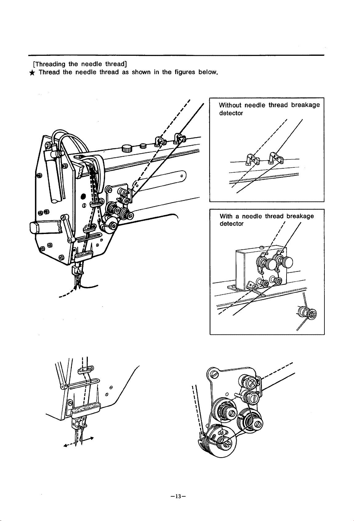
[Threading the needle thread]
* Thread the needle thread
as
shown in the figures below.
,
,
,
,
,
,
,
,
Without needle thread breakage
detector
With a needle thread breakage
detector
-13-
Page 17
CORRECT OPERATION
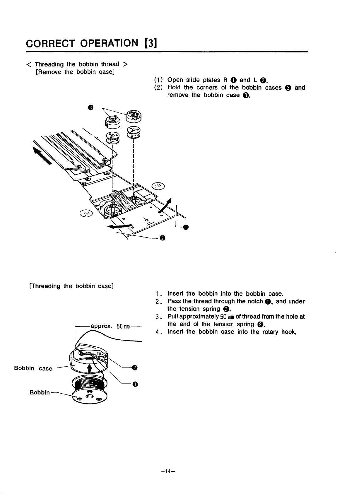
< Threading the bobbin thread >
[Remove the bobbin case]
[3]
( 1 ) Open slide plates R 0 and L
(2) Hold the corners of the bobbin cases 0 and
remove the bobbin case
8.
0.
[Threading the bobbin case]
Bobbin case
Bobbin
•
1 • Insert the bobbin into the bobbin case.
•
Pass
2
3 • Pull approximately
4.
the thread through the notch
the tension spring
the end of the tension spring
Insert the bobbin case into the rotary hook.
8.
50
mm
of thread from the hole at
8.
0,
and under
-14-
Page 18

< Holding the needle and bobbin threads >
* Insert the bobbin case (bobbin) into the rotary hook, and close the handle.
• Hold the needle thread by hand, and turn the
1
pulley by hand to bring the bobbin thread up.
2.
Set THREAD TRIMMER 0 to NEEDLE to lower
the needle thread trimmer knife.
Note.
Bobbin thread
THREAD
TRIMMER
Needle
thread
Be careful to keep the hands and other articles
away from the knife when it operates.
3.
Set the two needle threads
trimmer knife.
4.
Return THREAD
thread trimmer knife and
threads.
5.
Set THREAD TRIMMER 0 to LOWER to turn the
bobbin thread knife
below.
• Insert the thread into the groove
6
plate, and reset THREAD TRIMMER 0 to cut
and hold the bobbin thread with the bobbin
thread knife.
THREAD
TRIMMER
TR_IMMER
90°
as
on
the needle thread
0 to raise the needle
hold the needle
shown
in
the figure
in
the needle
0
{To
reverse the carriage feed}
1 . Return the slide plates.
2.
Set CARRIAGE
* If MODE 0 is set to any position other than MANUAL, the carriage feed will retract to the
home position quickly.
CARRIAGE
FEED
FEED
DlBI
~
0
8 to BACKWARD to retract the carriage feed.
MODE
•l·nlielf&Jii
•
MM"fllt·!M
•
PROGRAM
•
KNIFE
CHANGE
&CYa.EPGM.
-15-
Page 19

TREADLE AND START SWITCH DESCRIPTION
* When running a flap sewing program, the machine will not operate when the start switch is
pressed
* During normal sewing, the machine will operate when the start switch
plate
unless the flap presser is down.
operates.
is
pressed after the folding
* Set MODE to either AUTOMATIC or MANUAL.
< Treadle operation >
1 • When the treadle 0
presser foot spring L 0 will rise.
• When the treadle 0 is released, padding cloth presser foot spring R
2
presser foot spring L 0 will descend.
3
• When the treadle 0 is pressed to position
4
• When the treadle 0 is pressed to
5.
When the treadle 0 is pressed to position
operate.
* The folding plate will operate
6 • When the treadle 0
7.
When the treadle 0 is pressed to position
• Press the start switch 0
8
* When MODE is at MANUAL, the carriage feed will move without actually sewing.
* The order in which the carriage feed and flap pressers operate (3,
changed by resetting the
is
pressed, padding cloth presser foot spring R
1,
carriage feed ( L) 8 will descend.
positio~
0.
25-0.
is
pressed to position
and
the carriage feed will operate. ·
DIP switches. (p.
2,
carriage feed (
3,
binder 8 will descend, and the folding plate will
35
sec. after the binder
4,
flap presser ( L) 0 will descend.
5,
flap presser (
50)
R)
f)
and padding cloth
f)
and padding cloth
R)
8 will descend.
~perates.
0 will descend.
4,
6,
7 above) can be
I
BAs-6YY]
Neutral
(center)
position
-~45
0\
~t~==~~==~---
lsAS-601
-16-
Page 20

< Setting the material >
* When running a flap sewing program, the machine will not operate when the start switch is
is
in
down.
place.
0.
25,.....,0.
is
pressed after the folding
,.....,3
are unnecessary.
1,
carriage feed (
35
sec. after the binder operates.
4,
flap presser ( L) • will descend.
5,
flap presser (
L)
0 will descend.
R)
0 will descend.
pressed unless the flap presser
* During normal sewing, the machine will operate when the start switch
plate operates.
1 . When the treadle 0 is pressed, padding cloth presser foot spring R 8 and padding cloth
presser foot spring
2 • Set the padding
3 . When the treadle 0 is released, padding cloth presser foot spring R 8 and padding cloth
presser foot spring L
* If the padding
4 . Set the bodice
5 . When the treadle 0 is pressed to position
6.
When the treadle 0 is pressed to position 2, carriage feed ( R) 8 will descend.
7 • Set the welting
8 . When the treadle 0 is pressed to position 3, binder C) will descend, and the folding plate will
operate.
(The binder
C) will descend to hold the welting, and the welting will then be folded. )
L 0 will rise.
(or
material)
0 will descend to secure the padding.
is
sewn to the material already, steps 1
in
place.
in
place.
* The folding plate will operate
9 . Set one of the flaps, right or left.
10.
When the treadle 0
11.
When the treadle 0
12.
This completes material setting.
is
pressed to position
is
pressed to position
1 • Padding presser
• Welting material
3
2.
4.
Bodice
Flap
-17-
~ding
plate
Page 21

ADJUSTING THE MARKING LIGHT
Adjust the focus before setting the material
Focus adjustment
1
• The marking light will come
2 • Loosen screw 8
material are sharply focused.
Loosen
start· and sewing end positions.
bolt 0 and adjust the crosshairs
and
raise or lower the lens hood 0 so that the crosshairs
on
when the power switch 0
in
place.
is
set to ON.
rffiJ
so that they are focused precisely at the sewing
* Use Allen bolts 8 to adjust the sewing start position forward or back.
rt±tJ
projected
on
the
* Three marking lights
can
be installed with option
-18-
808367-000.
Page 22

PROGRAMMING(Entering
a standard sewing program)
* Set MODE to PROGRAM. The PROGRAMMING NUMBER and SEAM LENGTH indicators will
blink~
* Flap sewing is selected if
< Entering a standard sewing program >
Change the seam length
1 • Set MODE 0 to PROGRAM.
2 • Press SELECT 8 so that programming number indicator 1 lights.
3 • Enter the seam length for the standard sewing program.
Press switches
4.
Change MODE 0 to any position other than PROGRAM.
* Changes
turned off before resetting MODE, the changes will not be stored
5.
Set MODE 0 to AUTOMATIC to sew.
0 to change the seam length display from 1
in
the program settings are stored when the MODE switch is reset. If the power
F-
:J
or
F-C are displayed.
of
programming number 1 from 1
Program
00
to
125.
00
to
125.
in
the program.
is
MODE
•l·!•ll•lt~!·!lll
•lht.Ji!ft.IM
•
PROGRAM
•
KNIFE
CHANGE
&CYa.EPGM.
0
.ROGRAMMING
UMBER
1
2
@©)@@@
4
3
5aECT[EfDJ
CYCLE
PGM.
J
CD)
MODE
i •
H•ii~tiill
•
IM.nlrt.!M
•
PROGRAM
•
KNIFE
CHANGE
&CYa.EPGM.
PROGRAMMING
NUMBER
4
1 2
~@@@©)
3
DCQCJ
I~-------.
5
125
-EAM
NGTH
I
f
----tJ
(Q)BOBBIN
COUNTER
,-,
II
,_,
,_,
SET
I
s~---~E
DOD
__
EAM
<
~ENGTH
5
I
'·
S
>-----~
@BOBBIN
-,
,-
c
='
DOD
SET
D
COUNTER
SET
I
SET
E
D
-19-
Page 23

PROGRAMMING(Enterlng
a flap sewing program)
* Flap sewing programming is not possible
* Set MODE to PROGRAM. The PROGRAMMING NUMBER
blink.
* Flap sewing
F-:J indicates right flap, F-C indicates left flap sewing.
is
selected if
F-::J
or
F-[
on
BAS-600.
are displayed.
and
SEAM
LENGTH indicators will
* Correct the sewing start position (correction data).
< Entering a flap sewing program >
Change programming number 2 to right flap sewing, and correct the sewing start position.
• Set MODE 0 to PROGRAM.
1
2.
Press SELECT 8
3
• Select flap sewing
Press switch
Press switch 8 ( 1 's place) to display
4 . Set the flap. (See page
5 . Press the start switch
0
so
that programming number indicator 2 lights.
and
either right or left flap.
(100s
place) to display
:::J
17
for setting the flap. )
8.
F.
•
A
0
MODE
•l·l!il•lt!!·lll
•
16!Mft.!M
•
PROGRAM
•
KNifE
CHANGE
&CYa.EPGM.
~PROGRAMMING
NUMBER
CYCLE
4 5
PGM.
1 2 3
@(f)@@@
SELECT
[OfDJ
-~~~TH
[F
@~:eR
- c
Jl
SET
...
BOBBIN
I I 1-1
,
SELECT
0@@@
COUNTER
,-,
,_,
,_,
N0.1
N0.2 N0.3
~9--Q
-20-
Page 24

6 • The flap sensor will detect the flap edge, and the carriage feed will move forward
stop.
The distance moved after
display:40.
7.
Set CARRIAGE
flap edge is at the sewing start (needle) position. ·
the
The carriage feed can be moved
8
• Press
The carriage feed will return to the home position, and the correction data shown
COUNTER display will
If EMERGENCY STOP 0
return to the home position but the correction data will not be stored.
9.
Changes
PROGRAM.
* Changes
is turned off before resetting
0.
FEED
SET
switch 8 after the sewing start position is located.
in
the program will be stored when MODE switch 0 is reset to any position other than
in
the program settings are stored when the MODE switch 0 is reset. If the power
material edge detection will appear in the BOBBIN COUNTER
switch 0 to FORWARD or BACKWARD to move the carriage feed so that
in
0.
2
mm
steps.
be stored.
is
pressed without pressing
MODE, the seam length will not be changed.
SET
switch
8,
the carriage feed will
40
in
the BOBBIN
* If the only change to be made is the right or left flap selection, steps 4_,8 can be skipped.
mm
and
EMERGENCY
0
~
BOBBIN
COUNTER
STOP
I
SET
CARRIAGE
FEED
~
I
~40mm]
)
~
~-----------------)
I
I
~~-..
I
-21-
Page 25

PROGRAMMING(Entering
a cycle sewing program)
* CYCLE
order.
* See the preceding pages to set a standard or flap sewing program
PGM
allows up to six selections from
any
of program numbers
1-5
in
< Entering a cycle sewing program >
Set a 1
1
• Set MODE 0 to KNIFE CHANGE & CYCLE
2.
Press CYCLE PGM. CLEAR
3 • Press SELECT 0 to select program number
4.
Press CYCLE PGM.
5 • Press SELECT 0 to select program number
6.
Press CYCLE PGM.
7 • Press SELECT 8 to select program number
8.
Press CYCLE PGM.
9 • Press SELECT 8 to select program number
10.
Press CYCLE PGM.
11.
Reset MODE 0 to any position other than KNIFE CHANGE & CYCLE PGM.
© If stacker operation
© If stacker operation
© See page
* The changes
* If a mistake
-+ 2 -+ 1 -+
after the last program number (3 above) to program stacker operation at that time.
last program number (3 above) to program stacker operation at that time.
34
sewing cycle
3 sewing cycle.
PGM.
f).
1.
SET
0 to store program number
2.
SET
0 to store program number
1.
SET
0 to store program number
3.
SET
0 to store program number
is
not programmed, stacker operation will be automatically programmed
is
not programmed, a period
to operate the stacker independently.
in
the sewing cycle are stored when MODE 0 is reset. No changes
will be stored if the power is turned off without resetting MODE.
is
made
in
the order, press CLEAR
1.
2.
1.
3.
".
" will be automatically entered after the
f)
and reprogram from the beginning.
to be combined
program numbers
in
any
1-5.
in
the
-22-
Page 26

MODE
.ROGRAMMING
UMBER
(Q)SEAM
LENGTH
(Q)BOBBIN
COUNTER
SET
_.
BOBBIN
COUNTER
•I·!•II•M!·III
·•M.u&IHM
•
PROGRAM
~
•
KNIFE
CHANGE
&CYCLEPGM.
1 2 3
@@@(Q)@
4
5
[-
-
s~---~E
DODD
~J
I
•
Cycle
1-+2-+1-+3
t
< Checking the sewing cycle >
1 • Set MODE 0 to KNIFE CHANGE & CYCLE PGM.
The order of the program cycle
sewn
Sewing order
repeatedly
will be displayed •
-ll
© Program number
(-
SET
1 2 3 4 5
.8.©©
-
SELECT@
II
II
N0.1
-]
@@
N0.2 N0.3
•
MODE
•1·!111•1~!·11
•
MM.Jfl*HM
•
PROGRAM
'
~
•
KNIFE
&CYCLEPGM.
0
II
CHANGE
ROGRAMMING
-
UMBER
1 2 3
@@@@@
O[EfCLEARU
CYCLE
4 5
PGM
(Q}~~~TH
I
[
•C
S
?----~
DOD
-23-
@~g~~~R
-,
:
ll
SET
E
SET
D
The period
stacker operation.
_.
BOBBIN
COUNTER
-,
-=~-
SELECT
@@@
N0.1
D
N0.2 N0.3
"."
after the 3 indicates
-
I
Page 27

PROGRAM CONFIRMATION
* The carriage feed can be moved to check the sewing operation without actually sewing.
1
• Set MODE 0 to MANUAL.
• Press SELECT 8 to select program number 1
2
Set STACKER 8 to
Set STACKER 8 to OFF if stacker operation
Set the material in place.
3 .
4 •
Press·
The carriage feed will advance to the sewing start position.
• Press the start switch 8 again.
5
The carriage feed
shortened)
• Continue pressing the start switch 8 to advance the carriage feed to the next step.
6
the start switch
or
backstitch seam.
* If the start switch 8 is pressed at the
backstitch sewing, the carriage feed will move to the corner knife position.
7.
The carriage feed, flap presser, and binder will rise, and the stacker will operate.
The stacker
8.
Press the start switch 8 again.
The carriage feed
will not operate if STACKER 8
* If EMERGENCY STOP
stop and return to the home position.
ON
to operate the stacker.
8.
will advance to the end point of the condensed seam (stitch length
5th
will return to the home position.
C)
is
pressed between steps 5 and 7 above, the carriage feed will
stitch
is
"'5.
i&
not necessary.
in
condensed seam sewing or the
off.
7th
stitch
is
in
MODE
•
!·!liie!M5i!i
•
Mf&UIW•·
•
PROGRAM
•
KNIFE
&CYa.EPGM.
0
EMERGENCY
Ov
/
BOBBIN
COUNTER
CHANGE
STOP
I
/A\
PROGRAMMING
'@II
NUMBER
1 2 3 4 5
@)(Q)(Q)@(Q)
SELECT
i(f[jl
~CYCLE
SET
PGM.!!J
STACKER
8
-24-
\,
Page 28

SEWING
* If the temperature
work pieces before beginning regular operation.
1 • Set the power switch 0 to ON.
2.
Press EMERGENCY STOP
3.
Set MODE 0 to AUTOMATIC.
To use the corner knife, turn CORNER KNIFE 0 and CENTER KNIFE 8
To use the center knife, turn CENTER KNIFE 8
* When CENTER KNIFE 8
is
on.
4.
To use the stacker, turn STACKER 0
If the stacker
* When
• Set the material
5
6 • Press the start switch
The selected automatic sewing procedure will begin.
in
selected program number is not one included
is
below
5°C,
sewing machine operation will be sluggish at first. Test sew
8.
on.
is
off, the corner knife will not operate even if CORNER KNIFE 0
on.
is
not used, turn STACKER 8 off.
the cycle sewing mode, the stacker will not operate even if STACKER e
in
the sewing cycle. (See
in
place. ·
0.
MODE
1
•l·l•il•lt~!·lil
•
1~!·!11•!·1•
•
PROGRAM
•
KNifE
CHANGE
&CYCLEPGM.
on.
p.
is
22,
on
2-3
if the
34.
)
EMERGENCY
~
0~
ll
OBBIN
COUNTER
STOP
SET
CORNER
KNIFE
* The carriage feed can be moved to provide more working space
in
material
* When DIP switch
returns to the home position after sewing
the start switch
* If the treadle
carriage feed can be returned to the home position with the start
ON-OFF setting of the above DIP switch.
place.
3-3
on
the main circuit board is
is
completed is regulated by the start switch
0.
is
pressed back when the carriage feed
-25-
on,
the timing at which the carriage feed
is
at the corner knife position, the
CENTER
KNIFE
on
the table when setting the
STACKER
0.
switc.h,
regardless of the
Press
Page 29

< Setting the bobbin counter >
1 • Set MODE 0 to AUTOMATIC.
2.
Press SELECT 8 to select the bobbin number
3.
Press BOBBIN COUNTER SET
The number of work pieces previously set for that bobbin
SET
COUNTER
• Use switches 8 to change the setting.
4
• Press SET 0 when the changes are completed or if no changes are made.
5
(The number shown
COUNTER
BOBBIN COUNTER
The
display.
display. )
in
the BOBBIN COUNTER
SET
0.
The BOBBIN COUNTER
indicator will go
1-3.
SET
out.
SET
indicator will blink.
will be shown
display will appear
in
the BOBBIN
in
the BOBBIN
MODE
~
•l·!lll•ltu.llll
•
16f.Uilt·1M
•
PROGRAM
•
KNIFE
&CYCLEPGM.
CHANGE
@PROGRAMMING
NUMBER
1 2 3
@@@@©
4
DCOLCJ
(Q)SEAM
LENGTH
5
'''''-'_!II''~'~
:::'1
~I
::
..
f
~
......
,,,,,"''''
S
~----<:
DOD
'
•
< Checking the number of work pieces >
1 • Set MODE 0 to AUTOMATIC.
2.
Set THREAD TRIMMER
The counter will increase by one each time a piece
can be counted.
MODE
rB
•l·!lll•lt~l·lill
•IMUIIHM
•
PROGRAM
•
KNlfE
CHANGE
&CYCLEPGM
@PROGRAMMING
NUMBER
1 2
@@@@@
DCQCJ
•
f)
to NEEDLE.
4 5
3
@~~~TH
,-,
fff
S
DOD
.BBIN
.
OUNTER
SET
C:
-·--
I
SET
E
~~
v
.
8
:?----~
J
is
completed. From
@~g~:eR
,-,
,-,
E
...
BOBBIN
(
SELECT@
SET
I
SET
D
COUNTER
EMERGENCY
l
(Q) (Q)
N0.1
NOHO~
0-999,
-+
BOBBIN
,-,
,-,
,,,
SELECT@
II
II
N0.1
.~~
BOBBIN
999
COUNTER
,-,
@ @
N0.2 N0.3
STOP
I
COUNTER
work pieces
SET
THREAD
TRIMMER
•
< Clearing the work piece counter display >
1 . Set MODE 0 to AUTOMATIC.
2.
With THREAD TRIMMER
be set to
MODE
kj
•l·l•ll•ltJ!·Iil
•
•MMIH•
•
PROGRAM
•
KNIFE
&CYCLEPGM.
0.
CHANGE
(Q)SEAM
LENGTH
[
S
DOD
•
f)
set to UPPER, press BOBBIN COUNTER
(Q)BOBBIN
COUNTER
Jl
?----~
E
SET
SET
D
-+
(
SELECT
0©>
-26-
BOBBIN
N0.1
N0.2 N0.3
COUNTER
")
'-'·
©> ©>
SET
EMERGENCY
v
~
BOBBIN
COUNTER
0.
The counter will
STOP
l
SET
THREAD
TRIMMER
l!liBI
r£f
I
Page 30

< Stitch tension >
1 • Bobbin thread tension
2
• Needle thread tension
* The bobbin thread tension varies with material and
thread. Turn adjusting screw
tension.
Standard tension is
materials when working with a
thick
yarn.
40..-.,;50
0 to adjust the
g for medium-thick t6
#50
spun
• Thread take-up spring
3
* Turn tension control nut
Greater
Smaller f'-.....:_ 0 a
• w
f)
to adjust the needle
thread tension.
Once the bobbin tension has been adjusted,
adjustment of the
provide a
clean, even seam.
0
needle thread tension alone can
~
:ip
4
Evenly tensioned seam
Needle thread tension is
too
high,
thread tension is too low.
/? Needle thread tension is
! too low, or bobbin thread
tension
Is
or
bobbin
too high.
\
\
\_.
* Range of thread take-up spring operation
of
Standard range
To adjust the range of thread take-up spring 8 operation, adjust stopper
thread take-up spring operation is
* Thread take-up spring tension
Standard thread take-up spring tension is
To adjust, loosen screw 8 and turn tension stud
20..-.,;40
-27-
7..-.,;10
g.
fj.
mm.
8.
Page 31

CENTER KNIFE POSITION ADJUSTMENT
* Adju stment of the
E
1 .
2.
x.
The hi
p
gher the number of the center knife pos ition, the fa
os
itioned.
Change the sewing start [ill value fr om 5 to 6, and the sewing end ~ value from 5
Pr
ess the switch 0 for
Pr
ess the swi
* If
the abo
l1J)l.AlifiiE
-----
CENTER K.
ce
nter knife position should be done
th
e sewing start [ill position
tc
h 8 for
ve chan
th
e sewing start ~ position
ge
is made
bef
ore sewing start
acco
rding
to
rth
er
to
chan
ge
to
chan
ge
s,
the machine may
the thickness of the materia
inside
the 5 to a 6.
the 5 to a
the
be
..
corner knife is
to
7.
in any mode.
l.
7.
601
601
Sewing start Sewing end
~-----------
-~---
-
s
o---
-9
---
----~
-------
----
-
-
E
9
--0
-28-
Page 32

CORNER KNIFE POSIT.ION ADJUSTMENT
* Adjustment of the corner knife position should be done according to the thickness of the material.
The higher the number
_ positioned.
Ex.
Change the sewing start value from 5 to
1 • . Set MODE 0 to PROGRAM.
2 • Press SET·
The corner knife position will be shown
3.
Press SEAM LENGTH switch 0 to display a
4.
Press SEAM LENGTH switch 8 to display a
5.
The new corner knife position will be stored when
other position from PROGRAM.
If the power is turned off without pressing
not be stored.
8.
* The corner knife will not operate when the center knife is off (even if the corner knife switch
is on).
of
the corner knife position, the farther inside the corner knife is
6,
and
the sewing end value from 5 to
in
the display.
6.
7.
SET 8 is
SET
or changing the MODE position, the change will
pressed
or
MODE 0
is
reset to
7.
any
MODE
j •IIIIIGil
1•
0
s
o-
•IMU!it·!M
PROGRAM
•
KNIFE
CHANGE
&CYa.E
PGM.
-9
@PROGRAMMING
NUMBER
1 2 3
@@@@@
4 5
(Q)SEAM
LENGTH
,-
-
~
S
~---~
(Q)BOBBIN
,-
='
0[0LEO.J
~~~
9--0
E
(Q)SEAM
LENGTH
,-
o-
S
~-----c;
DODD
@BOBBIN
-,
COUNTER
SET
I
E
SET
COUNTER
f
I(
E
SET
SET
...
BOBBIN
COUNTER
(
SELECT@
II
,,
...
BOBBIN
N0.1
l
@@
N0.2 N0.3
COUNTER
l
SELECT
D@@@
N0.1
N0.2 N0.3
-29-
Page 33

FLAP SENSOR SENSITIVITY ADJUSTMENT
< Adjusting flap sensor sensitivity >
1 • Set MODE 0 to PROGRAM, and set a seam length of
2.
Set MODE 0 to MANUAL.
3
• Set a piece of material
wear.
• Press the start switch
4
The carriage feed will move to the sewing start position,
sensitivity
• Move the carriage feed by
5
will be monitored.
8 for the flap sensor is under the sensor
Sensor sensitivity can now be adjusted
page.
6
• Move the carriage feed by hand from position A to B (the full length of the sensor window), and
make sure the FLAP SENSOR indicators
7.
When adjustment is completed, press EMERGENCY
The carriage feed will return to the home position.
in
place
f).
so
the rubber padding
hand
forward from the position at which it stopped so that the window
e.
as
described under "Sensitivity adjustment"
e,
& do not light.
190
mm.
on
the back of the carriage feed does not
and
flap sensor e (both right and left)
.
on
the next
STOP
0.
MODE
fi
•1·!111•1~tHUI
)
~.
·~t!ll!!·!·
•
PROGRAM
•
KNFE
CHANGE
&CYCLEPGM.
0
EMERGENCY
(Q)
v
BOBBIN
STOP
COUNTER
SET
@~~~TH
@~:m
I I
,-,
-;
,-,
,_f,
! f
S
~----~
SET
I
E SET
DODD
•
•
8 A
,..,..
______
I I
,
•
-30-
Page 34

< Sensitivity adjustment >
1 . With the reflector positioned
SENSOR indicators 0 and 0 are
2. Turn the controls another
3 .
Set a
lights.
piece
of material over the reflector now, and make sure the FLAP SENSOR indicator
-H----0
'--~---0
below
45•
clockwise
the sensor, turn sensitivity controls 0 and 0 so that FLAP
between
on
and off.
from this position.
L__--':::::======l-
Be sure
sewing.
to
Flap
sensor
lamp
~Hl--
clean the lamp behind the flap sensor and the reflector (folding plate) top before
---0
-tt---
0
Reflector
(f
olding plate )
-3
1-
Page 35

TROUBLE
* The machine will stop automatically if trouble develops while sewing.
·<
UPPER
THREAD BREAKAGE indicator lights >
EMERGENCY
~
BOBBIN
*
0
STOP
COUNTER
SET
TROUBLE
•
UPPER
THREAD
BREAKAGE
©)BOBBIN
EMPTY
©~
1 • Press EMERGENCY STOP
will advance.
2
• Thread the needle thread.
01
1
0 Left thread
0.
Right thread
< BOBBIN EMPTY indicator lights >
• Set MODE 0 to AUTOMATIC, and set the number of work pieces for the bobbin
1
SET
COUNTER
2.
Set MODE 0 to MANUAL.
3.
Set CARRIAGE
4
• Replace the bobbin with a full bobbin.
* See page
0 display. (p. 26)
FEED
26
8 to FORWARD. The carriage feed will advance.
for resetting the bobbin counter.
The carriage feed
in
the BOBBIN
MODE
i)
•l·llii•JII'Iill
• lti!·!llll·!·
•
PROGRAM
•
KNFE
&CYa.EPGM.
0
EMERGENCY
oil
BOBBIN
COUNTER
CHANGE
STOP
II
SET
'"'''''''-"''""'''
~I
1-1
:,,,,,:
,,,,,I
s?
____
II:
ll~lllll~''"
~E
DOD
TROUBLE
©:~
•
BOBBIN
EMPTY
©~
I (
SET
__
SELECT
0
CARRIAGE
FEED
-----..JJ
@@@
N0.1
N0.2
N0.3
-32-
Page 36

< PROGRAMMING
ERROR
indicator lights >
* If the sewing range exceeds 28-190
50
mm,
re-enter the correct value. (Range
* If the indicator lights
is
an
There
error
in
the AUTOMATIC
in
the data. Re-enter the data
mm
while programming,
is
36,..,.,
or
MANUAL mode
or
if the flap seam is set to more than
190
mm
for a gauge width of
in
the PROGRAM mode.
16......,20
mm.
)
MODE
.
«·mi•JM@i
•
MM"fflf.!M
•
PROGRAM
t
•
KNIFE
&CYCLEPGM.
CHANGE
EMERGENCY
oil
BOBBIN
STOP
II
COUNTER
SET
< EMERGENCY STOP >
Press EMERGENCY STOP 0 to stop carriage feed movement.
EMERGENCY
BOBBIN
COUNTER
STOP
SET
TROUBLE
©UPPER
©
THREAD
BREAKAGE
BOBBIN
EMPTY
·~lNG
0
Resetting after
* When EMERGENCY STOP
move to the thread trimming position, and the carriage feed will rise. The needle and bobbin
thread trimmer knives can be operated
Press EMERGENCY
the home position.
an
emergency stop
STOP again, and press the start switch
Sewing
is
pressed again, the needle thread will be cut, the carriage feed will
at this time.
on.
The carriage feed will return to
is
possible.
EMERGENCY
BOBBIN
STOP
COUNTER
SET
-33-
Page 37

OPERATING THE STACKER DURING CYCLE SEWING
Ex.
Program the following cycle: program # 1 --+ 2
operation.
Set MODE 0 to KNIFE CHANGE & CYCLE PGM.
1 .
2.
Press CYCLE PGM. CLEAR
3 • Press SELECT 8 to select program number
4. Press CYCLE PGM.
5 • Press SELECT 8 to select program number
6.
Press CYCLE PGM.
7 • Press bobbin counter
program cycle.
SET
SET
SET
f).
8 to store program number
8 to store program number
8.
A period
".
" will be displayed to store stacker operation
* The stacker does not operate while the period
• Press SELECT 8 to select program number
8
9.
Press CYCLE PGM.
10.
Press SELECT 8 to select program number
11.
Press CYCLE PGM. SET 8 to store program number
12.
Press bobbin counter
program cycle.
13.
Reset MODE 0 to any position other than KNIFE CHANGE & CYCLE PGM.
SET
8 to store program number
SET
8.
A period
"."
will be displayed to store stacker operation
1.
2.
1.
3.
--+
stacker operation --+ 1 --+ 3
1.
2.
".
" is blinking.
1.
3.
--+
* Changing the MODE 0 selection stores the order of the sewing cycle. No changes
sewing cycle
* If a mistake
will be stored if the power
is
made
in
the order, press CLEAR
is
turned off without resetting MODE.
f)
and reprogram from the start .
stacker
in
the
in
the
in
the
MODE
•
I·""'W·ii'
•
'·'Mfiit·iM
•
PROGRAM
'
~
•
KNIFE
CHANGE
&CYCLEPGM.
0
MODE
•
11111•!!·!11
•
1!!·!111!·!·
•
PROGRAM
~
~
•
KNIFE
CHANGE
&CYCLEPGM.
0
•
ROGRAMMING
UMBER
1
2
4
3
5
©©©©@
~~;JJ
.ROO
1
©©©©©
RAMMING
UMBER
2 3
4 5
@~~~TH
I
f
S
:?----~
©~Jrm
~,.,
..
~
,
~;;:
,,,
_....._,*
,,,.
,,.
E
DOD
@~~~TH
I
fl
@~~~R
-,
-.
I
f
SET
I
SET
D
SET
I
_.
(-
SELECT©
II
_.
(9.-
SELECT©
DCQCJ
Do0f5
-r
II
BOBBIN
-
II
N0.1
BOBBIN
,,
N0.1
N0.2 N0.3
COUNTER
-]
© ©
N0.2 N0.3
COUNTER
-]
©@
-34-
Page 38

STANDARD
ADJUSTMENTS<sewing
< Needle installation >
machine head)
* Loosen Allen screw
•
Long
groove
•
< Upper and lower shaft timing adjustment >
the way
an
Use
0,
and insert the needle 8 all
in
with the long groove to the inside.
MtX
190
needle •
1 • Remove the needle.
2.
Tilt the machine and remove the timing belt
3.
Align marker A
4 • Without moving the upper shaft, align the arrow
line, and remount the timing belt.
5 . Right the machine and install the needle.
on
the pulley with the red index.
0.
on
the lower belt 8 with the arm bed reference
< Needle and rotary hook timing adjustment >
[Needle to rotary hook point gap]
Needle
Rotary
hook
point
-H---
Max.
0.05
mm
1 • The gap between the needle and rotary hook point should be
and ©, and shift the rotary hook base 0 right
• The gap between the rotary hook base 0 inside and the lower shaft gear
2
0.
2
mm.
approximately
Shift the lower shaft gear
or
left to adjust.
f)
right or left to adjust.
0.
05
mm.
Loosen screws ®, @,
* Be sure that the screw stop does not change when screws © are tightened to gear
f)
should be
f).
-35-
Page 39

[Rotary hook to needle plate gap]
* The gap between the rotary hook 8 and needle plate 8 shouid be
and raise or lower rotary hook 8 to adjust.
[Needle bar
0
lift stroke and needle bar height]
~Needle
0.
6-0.
9
mm.
Loosen screw 0
I
1 , 1
-1.
:I
I I
I I
ll
1/
Needle bar lift stroke
• The rotary hook point should be aligned with the needle center when the needle is raised
1
from the bottom point. Loosen screw 8 and turn rotary hook 8 to adjust.
Needle bar height
• The gap between the top
1
the rotary hook point is
needle bar to adjust.
5mm
2.4mm
of
the needle hole and the rotary hook point should be
aligned with the needle center. Loosen screw 8 and raise or lower the
1-1.
5
2.
mm
4
mm
when
[Rotary hook and bobbin case opener gap]
* The rotary hook 0 to bobbin case opener 0 gap
should be
is shifted all the way
Loosen screw
opener
-36-
0.
2
mm
0,
0 right or left to adjust.
when the bobbin case opener 0
in
the direction
and shift the bobbin case
of
the arrow.
Page 40

CARRIAGE FEED ADJUSTMENT
< Parallel adjustment of needle and carriage feed >
1 • Set the carriage feed to the stop position.
Move the carriage feed and make sure the needle and carriage feed are
the figure below.
parallel
as
shown
in
Adjustment
Loosen screws
Place a piece of material below carriage feed arms 8 and
clamp the
material at front and back.
e and
material. Now pull
0,
and adjust the angle of carriage feed arms 8 and left
on
the material to make sure the carriage feed evenly clamps the
< Carriage feed angle adjustment >
* Make sure the carriage feed angle
Adjustment
Loosen screws
e and
0,
and adjust the angle
is
properly adjusted for the material
• •
r-----
l
8,
and lower the carriage feed to
in
use.
of
carriage feed arms 8 and left
---
-----
----
_
___,
---
__
...._,
8.
8.
>????????????22???????2??22??2?2??{?????2???22?222?222??2??2?22??2
-37-
Page 41

< Carriage feed height adjustment >
* The front edge of the carriage feed should be approximately
20mm
..
-----.r--------~-----------qr
:
"'
I
20mm]
20
mm
high at the home position.
Adjustment
0,
Loosen nut
Loosen bolt
Before adjusting, turn the power switch off, move the carriage feed forward and back by hand,
and make sure the flap presser does not strike the machine.
and adjust bolt
fj
to raise the carriage feed, tighten the bolt to lower the carriage feed.
fj.
•
< Folding plate position adjustment >
Move the carriage feed, and make sure the edge of the carriage feed and the edge
plate are flush.
Also, the gap between the
folding plate is fully extended.
folding plate and needle should be approximately 1
of
the folding
mm
when the
* Move the carriage feed, and make sure the gap between the folding plate and needle is
approximately 1
mm.
-J
o~-------r~
o
________
1
mm
_
1
mm
Adjustment
o Loosen bolts
carriage feed
plate.
o Loosen nut
stroke of the folding
Loosen nut 8 to increase the stroke
Tighten nut
0,
and bring the edge of the
flush with the edge of the folding
8,
turn nut
plate.
8,
and adjust the
8 to decrease the stroke.
-38-
Page 42

< Binder position adjustment >
•
0
5mm
approx.
1 • When the binder 0 is down, the gap between the edge of the binder 0 and the edge of the
carriage feed
parallel.
Adjustment
( 1 ) Loosen
parallel.
(2) Loosen bolt 8 and adjust the gap between the edge of the binder 0 and the edge of the
carriage feed
2
• When the binder 0
slide plate
Adjustment
Loosen nut
the slide plate
3 . The gap between the bottom of the
approximately
Adjustment
Loosen nut
height.
lift the material guide arm
Now
pressure.
8 should be approximately 1
bolt 8 and adjust the binder 0 so the edge of the binder and carriage feed
fJ
to approximately 1
is
down, the gap between the bottom of the binder 0 and the top of the
t)
should be approximately 1
0,
and turn shaft 0 so the gap between the bottom of the binder 0 and the top of
t)
is
approximately 1
1
mm.
0,
and adjust bolts
mm.
The gap at both ends of the binder 0 must be the same.
cloth guides G and the top of the binder 0 should be
CD.
Tighten bolts
4D
by hand to make sure the arm is returned by the spring
mm
mm
(on both sides).
mm.
1mm
(on both sides), and the edges should be
fJ
are
CD
to raise, loosen the bolts to lower the
-39-
Page 43

SENSOR ADJUSTMENT
< Needle thread knife sensor adjustment >
1 • Set MODE 0 to PROGRAM.
Set a seam length of
2.
Set MODE 0 to MANUAL.
3 . Set a piece of material
4 • Press the start switch
The carriage feed will move to the sewing start position.
5.
Set THREAD TRIMMER 0 to
The needle thread trimmer knife 8 will descend.
Adjust the timing at which the thread trimmer becomes off with
6.
Slide needle thread knife sensor 8 up or down and secure where the needle thread trimmer
8 will not strike the flap presser (folding plate).
knife
·*
When the needle thread trimmer knife 8 is off, the needle thread trimmer knife 8 will not
operate if the needle thread trimmer knife sensor indicator
150
mm.
in
place so the cushion
8.
UPPER.
on
the back
of
the carriage feed does not wear.
needle thread knife sensor
8
is
already
on.
8.
MODE
•l·!•ii•M~·!ill
•IM'f!lt·!M
Jf
•
PROGRAM
•
KNIFE
CHANGE
&CYCLEPGM.
.ROGRAMMING
UMBER
3
2
1
©)@©)@@
oco-oJ
CYCLE
•
MODE
~
•IPII•I~HIIil
) •
·~~!·!Ill!·!·
•
PROGRAM
•
KNIFE
CHANGE
&CYCLEPGM.
0
THREAD
TRIMMER
4
PGM
-~~TH
5
,
S
;?
•
DOD
I
,-
='
____
@gg~~R
II
,_.
~
E
SET
I
SET
D
....
(
SELECT@
II
BOBBIN
COUNTER
II
N0.1
N0.2
l
@@
N0.3
-40-
Page 44

< Corner knife adjustment >
1 • Set MODE 0 to AUTOMATIC.
2.
Set CORNER KNIFE
3 . Set a piece of material
4.
When the corner knife operates after sewing, adjust the position of the sensor 8 where the
alarm stops.
Make sure the
If the sensor position
The amount cut by the corner knife
the gauge. Make sure there
f)
and CENTER KNIFE 8 to ON.
in
place, and press the start switch
blade of the corner knife cuts the material at this time.
is
too low, the corner knife will not rise enough.
is
is
a 1
dimension
mm
allowance inside the seams.
B,
approximately 2
8.
mm
less than dimension A of
MODE
jJ
•l·!•ll•bU·!III
•
~~~!·!Ill!·!·
•
PROGRAM
•
KNIFE
CHANGE
&CYa.E
0
@PROGRAMMING
1
@@@©@
DCOLCJ
PGM.
NUMBER
3
2
4 5
CORNER
KNIFE KNIFE
El
CENTER
El
t
t
•
-41-
Page 45

STACKER ADJUSTMENT
< Bar stacker >
Make sure the stacker bar does not extend beyond the table.
A
Adjust
stacker
height with
bolts
Adjust the stacker stop position with nut
the
0.
Loosen
the
the stacker
f).
Cushion adjustment when stopping towards A
Tighten speed
stop speed.
Loosen speed
stop speed.
Cushion adjustment when stopping towards B
Tighten speed
stop speed.
Loosen speed
stop speed.
controller screw 8 to decrease the
controller screw 8 to increase the
controller screw 8 to decrease the
controller screw 8 to increase the
bolt 8
material drapes evenly over
and
plate.
adjust
so
* Adjust so that the recoil of the stacker bar does
not cause the bar to strike the machine when
stops.
that
it
Speed adjustment
Screw valve speed control screw 0
Loosen to increase the speed.
Speed adjustment
Adjust
valve speed control screw 0
in
direction A
in
direction B
in
(turn right) to decrease air cylinder speed.
as
above.
* If the stacker bar returns before the end of the cylinder 8 stroke when the stacker is operated
in
the AUTOMATIC or MANUAL mode, increase the speed so that the bar travels all the way to
the end of the stroke.
-42-
Page 46

< Pickup stacker >
Adjust
stacker
height with
bolts
0.
Flush
I
the
Loosen
just the chuck open-
nut 8 to ad-
opening
is
~:i:ll:li.'Sm
Adjust the stacker stop position with
of
the edge
flush.
the table
and
the edge
nut
f)
so
of
the chuck are
that
Adjust screw 0 to ad-
just the material release timing.
Cushion adjustment when stopping towards A
Tighten speed
stop speed.
Loosen speed controller screw
stop speed.
Cushion adjustment when stopping towards 8
Tighten speed controller screw
stop speed.
Loosen speed
stop speed.
controller screw C) to decrease the
C) to increase the
0 to decrease the
controller screw 0 to increase the
Speed adjustment in direction A
Screw valve speed control screw 0
Loosen to increase the speed.
Speed adjustment in direction 8
Adjust valve speed control screw
G
in
(turn right) to decrease air cylinder speed.
as
above.
-43-
Page 47

KNIFE REPLACEMENT
< Corner knife replacement >
1 . Set MODE 0 to KNIFE CHANGE & CYCLE PGM.
2.
Press EMERGENCY STOP
An
alarm will sound once, and the carriage feed will move to the knife replacement position.
alarm will sound once more when the carriage feed stops.
The
3.
Press EMERGENCY STOP 8 once more.
alarm will sound twice, the carriage feed and flap presser will descend, and the corner
The
will rise above the table.
knife
8.
* Keep your hands away from the knife.
AIR
OFF will be displayed.
4 • Turn air cock 8 to stop the air supply. (Bleed the air line. )
The corner knife
• Loosen screw
5
* Align the edge of the corner knife 8 with the edge of the knife bracket
6.
After replacing the knife, turn air cock 8 to restore the air supply.
7.
Press EMERGENCY STOP 8 again.
alarm will sound twice, the carriage feed and flap presser will rise, and the corner knife will
The
descend.
The carriage feed
MODE
will be locked in the up position.
8,
and replace corner knife
will move to the stop position, and the alarm will sound once.
8.
0.
•l·!lll•lll!·!il
•
1!!·!111!·!·
•
PROGRAM
g •
KNifE
0
l &
EMERGENCY
0
BOBBIN
Cautions
o If the air supply
above, the
the air
repeat steps 1 through
o If the corner knife
the figure, loosen screw 0 and adjust the angle of
the corner knife.
on
supply is restored later. If this happens,
CHANGE
CYa.E
PGM.
STOP
L I
I
COUNTER
installation
corner· knife will not descend even if
SET
is
not turned
is
not
on
· 7 above.
in
the center
again in step 6
as
shown
Align the edges.
in
X
_)_
__________
(,
-44-
Page 48

< Needle thread trimmer knife replacement >
1 • Set MODE 0 to MANUAL.
2.
MODE
0
.c.!llietfit.Ji!i
•IUUilt·!M
•
PROGRAM
•
KNIFE
CHANGE
&CYa.EPGM.
CARRIAGE
FEED
3.
4 • Remove screw
5 • Remove screw
Set CARRIAGE
carriage feed out of the way
replacement is easier.
Set the power switch 0 to OFF.
••
FEED
to FORWARD to move the
so
8,
and remove movable knife
0,
and remove fixed knife
that knife
* Installation is the reverse of removal.
0.
Cautions
o Adjust fixed knife 0 and spring 8 so that there
on
installation
is
no gap and pressure is applied by the spring.
* Increase the pressure if the knives do not cut properly.
o If the pressure
needle thread
is
increased too much, movable knife operation will become sluggish and the
will not be properly released.
-45-
Page 49

< Bobbin thread knife replacement >
MODE
fi
•I·I•II•J~!·!II
; } •
1~!·!111!·!·
•
PROGRAM
•
KNIFE
CHANGE
&CYa.EPGM.
0
CARRIAGE
FEED
1
• Set MODE 0 to MANUAL.
2.
Set CARRIAGE
carriage feed will advance.
3.
Set the power switch 8 to OFF.
4 • Remove slide plates right and left
5.
Tilt the machine.
• Loosen screw
6
7 . Remove the right front cover
the bobbin thread knife
the table.
* Installation
Cautions
o Be sure the bobbin thread knife e does not extend
above the top
o When the cylinder rod is fully retracted, the groove
in
with the groove
on
installation
the bobbin thread knife e should be aligned
THREAD
TRIMMER
FEED
0,
8 to FORWARD. The
and right the machine.
0,
and then remove
e from the underside of
is
the reverse of removal.
of
the needle plate.
in
the needle plate.
8.
,-Needle
plate
0
••
-46-
Page 50

< Center knife replacement >
1 • Set MODE 0 to MANUAL.
2.
Set CARRIAGE
3.
Set the power switch 0 to OFF.
4 • Remove screw
FEED
8,
8 to FORWARD. The carriage feed will advance.
and remove the center knife
* Installation is the reverse of removal.
0.
pressure.
ll
)
0
MODE
•
f·iliiett@Sii
~
elf&'JIIHM
•
PROGRAM
•
KNIFE
&CYCLEPGM.
CARRIAGE
FEED
CHANGE
·-·
Cautions
o Align the center knife 0 with the screw hole
on
installation
in
the center knife bracket
0,
and secure with screw
e.
o The tip of the center knife should be 8
the bottom of the center knife guide. )
') Set the power switch to ON, and make sure the center knife tip does not protrude from the center
knife guide
Adjust center knife pressure by loosening screws 0 and adjusting center knife bracket
0
Increasing the pressure too much will decrease center knife durability.
0.
< Fixed knife replacement >
1 • Set MODE 0 to MANUAL.
2.
.Set CARRIAGE
3.
Set the power switch 0 to OFF.
4.
Remove slide plates right and left
5 • Remove screw
6 . Remove screw
FEED
8,
0,
8 to FORWARD.
and needle plate
and fixed knife
mm
above the top of the needle plate. {Align the knife with
The carriage feed will advance.
O.
0.
0.
* Installation is the reverse of removal.
~--
0.
MODE
n .
t·l•ll·l~!·n•
f1
.
MM!f!WM
•
PROGRAM
•
KNIFE
CHANGE
&CYCLEPGM.
CARRIAGE
FEED
0
-47-
Page 51

DOUBLE WELTING
-+
SINGLE WELTING REPLACEMENT
< Changing from double to single welting >
MODE
1 .
UIIJtlmJB
•
~~~!·!Ill!·!·
•
PROGRAM
•
KNIFE
CHANGE
&CYa.EPGM.
1 • Set MODE to MANUAL, and forward the carriage feed to the thread trimming position.
2 . Change the binder
treadle, work the binder assembly, and adjust the height.
3
• Loosen ruler fitting plate 0 screws 0 and carriage feed
w
•.
4 . Slide ruler fitting plate 0 towards carriage feed arm L
Make sure there are no gaps between ruler fitting plate
0,
L
5.
Drain the air line, and remove spacer W 0
6 • Turn manual valve 0 for folding plate L off (down).
and then tighten screw
assembly from a double welting to a single welting binder. Press the
arm
0,
0,
L 0 screw
and firmly tighten screw
spacerS
O,
and remove spacer
0,
and carriage feed arm
0.
0.
on
the cylinder rod for folding plate
L.
< Changing from double to deformed welting >
-48-
Page 52

ERROR MESSAGES
* The machine will not operate when
LED
shown in the
Should
given
E-1-*
E-2-*
E-3-*
E-4E-6-
E-0-00
E-1-00
E-1 -0
E-1-02
E-2-00
E-2-0
an
error message be displayed, contact your Brother dealer. A list of error messages is
below.
* Switch-related error
* Machine-related error
* Carriage feed-related error
* * Sensor-related error
* * Thread breakage-related error
1
1
either when the power is turned
Error Contents
Pressed EMERGENCY STOP while carriage
feed moving
Start switch depressed when power turned
on.
Padding
depressed when power turned
Treadle depressed when power turned
Machine motor does not stop at needle up
position.
Needle not at
cloth presser foot assembly switch
up
position at sewing start.
an
error message (characters unrelated to the program) is
on
or
during sewing.
How to reset
following.
the start switch.
the treadle.
on.
on.
Refer to the
Release
Release the treadle.
Release
Turn the pulley to raise
needle.
the
Turn the power off.
E-2-02
E-3-00
E-3-01
E-3-02
E-3-03
E-3-04
E-3-05
E-3-06
E-4-01
E-4-10
E-5-00
E-6-0
Needle does not stop at up position at
sewing end.
Feed home position
Feed is overrun.
Increase feed time
Feed command wait
Feed error at error reset
Abnormal feed stop
Overrun to home side when power turned
Right flap sensor defect
Left flap sensor defect
Cycle program interrupted.
1
Right thread breakage
is
overrun (home side).
Turn the power off.
Turn the power off.
Turn the power off.
Turn the power off.
Turn the power off.
Turn the power off.
Turn the power off.
Move
the
on.
from
Same as emergency stop.
Same as emergency stop.
Cycle
and
Same
carriage
the
ooerator
program
automatically
as
will
emergency stop.
feed
bv
hand.
be
reset.
away
cleared
E-6-10
E-7-00
<Emergency
If EMERGENCY STOP is pressed while the carriage feed is moving, the feed motor and machine
motor
first turned
pressed.
will stop immediately. The machine will now be
Left thread breakage
Memory read error
stop >
on.
The carriage feed will be
(See p.
33)
in
in
the same position
-49-
the same status
Same
Replace the circuit board.
as
as
emergency stop.
as
when the power is
when EMERGENCY STOP is
Page 53

MAIN CIRCUIT BOARD DIP SWITCH DESCRIPTIONS
Be sure the power switch is OFF before resetting any DIP switches.
SWl
ON
Lock stitch
pitch
SW2
ON
sw21
.D
I
OFF
22 23
D D D D D D .
24
2s
2s
21
2
al
0
Fraying
prevention
Backstitch or
condense stitc
seam length
Condense
stitch pitch
Carriage feed
speed to
start
Carriage feed 1
speed
knife
sewing
oosition
to
corner I
position
1
PSW-15
PSW-16
I
(mm)
PSW-17
PSW-18
(mm)
I
PSW-22
1
I
PSW-23
ON:
Backstitch
OFF
ON
OFF
OFF
5.0
4.0
OFF
ON
OFF
OFF
1.0 1.2
0.8
ON : 20
OFF:
15
ON
: 20 m /min.
OFF:
15
OFF
ON ON
6.0
OFF
ON ON
m /min.
m/min.
m/min.
OFF:
ON
7.
ON
1.4
0
OFF:
Condense
2200
spm
SW2
Folding timer
PSW-25
PSW-26
Carriage feed
operating order
Flap
~resser
operatmg order
I
I
-50-
PSW-
OFF
OFF
Right
-.left
ON
27
OFF
mSEC
ON
OFF
Left-.
right
Right flap :
Left flap
Right flap:
flap :
Left
OFF:
OFF:
350
OFF
ON
Synchronized to
carriage
feed
Right
Left
Left
Right
Timer start
mSEC
ON
ON
Synchronized
to carriage
feed, flap
presser
--. left
--. right
--. right
--. left
Page 54

SW3
ON
sw31
32 33
. D D D D D D D .
I
OFF
34
35 36
37
3
81
0
I
Gauge
......
-------'--·
Thread
monitor
breakag
1
PSW-al
--"'--·
I
ON
:
8,
O_F_F_:
_16....:..,
ON : Exists
10,
12,
14
mm
_1~8,:.....-20_m_m
OFF:
______
None
__,
Carriage feed
osition
Stacker type
CHECK
ROUTINE
I
PSW-34
I
PSW-35
PSW-36
PSW-37
ON
: Start switch monitor exists
OFF
OFF
Pickup
ON
: Sensor INITI.
ON
: Memory INITI. W-CYCLE
ON
OFF
Bar
Roller
OFF
ON ON
ON
-51-
Page 55

MEMORY INITIALIZATION
* Used to initialize or clear the memory of sewing data required for a sewing procedure.
1
• Set the power switch to OFF.
Turn switch
2.
Set the power switch to ON.
The memory will be completely cleared, and standard data will be written to memory.
When writing is
bobbin counter indicators
3.
Set the power switch to OFF.
Turn switch 3-7
< Standard data contents >
3-7
on
the main circuit board to ON.
completed, the alarm will sound once, and program number indicators
1-3
will light.
on
the main circuit board to OFF.
1-5
and
Cycle sewing
Program
Program®
Program@
Program®
Program@
Flap correction
Flap correction ®
Flap correction
Flap correction ®
Flap correction @
Corner knife correction
Corner knife correction ®
Corner knife correction @
CD
CD
®·
CD
1
--+
28
50
100
150
190
40.0
40.0
40.0
40.0
40.0
5
5
5
2
mm
(36mm)
mm
mm
mm
mm
mm
mm
mm
mm
mm
-
-
-
5
5
5
--+
3
Corner knife correction ®
Corner knife correction @
Bobbin thread
Bobbin thread ®
Bobbin thread @
CD
5
5
100
150
200
-52-
5
-
5
-
Page 56

TROUBLE SHOOTING
Phenomenon
Needle thread
breaks
Bobbin thread
breaks
I Uneven
slit~
Cause Where to check
Bent needle, blunt tip
rotar}t
Installation.
hook to
l----------------1
l-----------------1
ti~.._N_e_e_d_l_e
Poor needle
Not threaded correctly.
Excessive needle thread
ten~ion
Wrong
bobbin case opener gap hook timing adjustment"
Poor needle to rotary
hook timing
Not threaded correctly.
Excessive bobbin thread
tension
Oil, thread trimmings in
bobbin case. trimmings and oil.
Bent needle, blunt
Needle·
Needle alignment Reinstall correctly.
Needle thread tension
Bobbin
thread
tension
ad-
justing screw
is
______
too tight.
_jl-----1
Solution
Replace.
See
"Threading
thread"
See "Stitch tension"
See "Needle
See
"Needle
hook
timing adjustment"
See
"Threading
thread"
Readjust.
Clean away all thread
the
and
and
the
needle
rotary
rotary
needle
Re~lace.
13
I Skipped stitches
Stitches do not
tighten.
Needle breaks
Needle doesn't
at
up
position.
stop
Bent needle, blunt
Incorrect needle Installation.
weak,or
range
Needle
thread
Bent needle, blunt tip
Poor
needle to rotary
Needle up stop element
ti~_l-----1
Is
too
small.
tension
Is
·--
Needle H Replace.
_j
Needle facing, height
1
strength, action
Needle thread tension
Bobbin thread tension
Needle facing, height
Needle
Position of needle up
stop element
See "Stitch tension".
See "Stitch tension".
See
"Needle
hook timing adjustment".
See "Position detector
and
rotary
1271
-53-
 Loading...