

Page 1

SERVICE MANUAL
BAS-311G
BAS-326G
Please read this manual before making any adjustments.
DIRECT DRIVE
PROGRAMMABLE ELECTRONIC PATTERN SEWER
Page 2
This service manual is intended for BAS-311G, BAS-326G; be sure to read the BAS-311G, BAS-326G instruction manual
before this manual.
Carefully read the “SAFETY INSTRUCTIONS” below and the whole of this manual to understand this product before you
start maintenance.
As a result of research and improvements regarding this product, some details of this manual may not be the same as those
for the product you purchased.
If you have any questions regarding this product, please contact a Brother dealer.
SAFETY INSTRUCTIONS
[1] Safety indications and their meanings
This service manual and the indications and symbols that are used on the machine itself are provided in order to ensure
safe operation of this machine and to prevent accidents and injury to yourself or other people.
The meanings of these indications and symbols are given below.
Indications
DANGER
The instructions which follow this term indicate situations where failure to follow the
instructions may result in death or serious injury.
CAUTION
Symbols
・・・・・・
・・・・・・
・・・・・・
The instructions which follow this term indicate situations where failure to follow the
instructions could cause injury when using the machine or physical damage to equipment
and surroundings.
This symbol ( ) indicates something that you should be careful of. The picture inside the triangle
indicates the nature of the caution that must be taken.
(For example, the symbol at left means “beware of injury”.)
This symbol ( ) indicates something that you must not do.
This symbol ( ) indicates something that you must do. The picture inside the circle indicates the
nature of the thing that must be done.
(For example, the symbol at left means “you must make the ground connection”.)
BAS-311G, BAS-326G
i
Page 3
[2] Notes on safety
Wait at least 5 minutes after turning off the power switch and disconnecting the power cord from the wall outlet
before opening the cover of the control box. Touching areas where high voltages are present can result in severe
injury.
DANGER
CAUTION
Environmental requirements
Use the sewing machine in an area which is free from
sources of strong electrical noise such as electrical
line noise or static electric noise.
Sources of strong electrical noise may cause
problems with correct operation.
Any fluctuations in the power supply voltage should
be within ±10% of the rated voltage for the machine.
Voltage fluctuations which are greater than this may
cause problems with correct operation.
The power supply capacity should be greater than the
requirements for the sewing machine's power
consumption.
Insufficient power supply capacity may cause
problems with correct operation.
The pneumatic delivery capability should be greater
than the requirements for the sewing machine's total
air consumption.
Insufficient pneumatic delivery capability may cause
problems with correct operation.
Installation
Machine installation should only be carried out by a
qualified technician.
Contact your Brother dealer or a qualified electrician
for any electrical work that may need to be done.
The sewing machine weighs approximately 88 kg.
The installation should be carried out by two or more
people.
Do not connect the power cord until installation is
complete. If the foot switch is depressed by mistake,
the sewing machine might start operating and injury
could result.
Hold the machine head with both hands when tilting it
back or returning it to its original position.
Furthermore, do not apply excessive force when
tilting back the machine head. The sewing machine
may become unbalanced and fall down, and serious
injury or damage to the sewing machine may result.
Be sure to connect the ground. If the ground
connection is not secure, you run a high risk of
receiving a serious electric shock, and problems with
correct operation may also occur.
The ambient temperature should be within the range
of 5°C to 35°C during use.
Temperatures which are lower or higher than this
may cause problems with correct operation.
The relative humidity should be within the range of
45% to 85% during use, and no dew formation should
occur in any devices.
Excessively dry or humid environments and dew
formation may cause problems with correct operation.
In the event of an electrical storm, turn off the power
and disconnect the power cord from the wall outlet.
Lightning may cause problems with correct operation.
All cords should be secured at least 25 mm away
from any moving parts. Furthermore, do not
excessively bend the cords or secure them too firmly
with staples, otherwise there is the danger that fire or
electric shocks could occur.
Install the safety covers to the machine head and
motor.
If using a work table which has casters, the casters
should be secured in such a way so that they cannot
move.
Be sure to wear protective goggles and gloves when
handling the lubricating oil and grease, so that they
do not get into your eyes or onto your skin. If the oil
and grease get into your eyes or onto your skin,
inflammation can result.
Furthermore, do not drink or eat the lubricating oil or
grease. They may cause diarrhea or vomiting.
Keep the oil out of the reach of children.
ii
BAS-311G, BAS-326G
Page 4
CAUTION
Sewing
This sewing machine should only be used by
operators who have received the necessary training
in safe use beforehand.
The sewing machine should not be used for any
applications other than sewing.
Be sure to wear protective goggles when using the
machine.
If goggles are not worn, there is the danger that if a
needle breaks, parts of the broken needle may enter
your eyes and injury may result.
Turn off the power switch at the following times. If the
foot switch is depressed by mistake, the sewing
machine might start operating and injury could result.
• When threading the needle
• When replacing the bobbin and needle
• When not using the machine and when leaving the
machine unattended
Cleaning
Turn off the power switch before carrying out
cleaning. If the foot switch is depressed by mistake,
the sewing machine might start operating and injury
could result.
If using a work table which has casters, the casters
should be secured in such a way so that they cannot
move.
Attach all safety devices before using the sewing
machine. If the machine is used without these
devices attached, injury may result.
Do not touch any of the moving parts or press any
objects against the machine while sewing, as this
may result in personal injury or damage to the
machine.
If an error occurs in machine operation, or if abnormal
noises or smells are noticed, immediately turn off the
power switch. Then contact your nearest Brother
dealer or a qualified technician.
If the machine develops a problem, contact your
nearest Brother dealer or a qualified technician.
Be sure to wear protective goggles and gloves when
handling the lubricating oil and grease, so that they
do not get into your eyes or onto your skin. If the oil
and grease get into your eyes or onto your skin,
inflammation can result.
Furthermore, do not drink or eat the lubricating oil or
grease. They may cause diarrhea or vomiting.
Keep the oil out of the reach of children.
Maintenance and inspection
Maintenance and inspection of the sewing machine
should only be carried out by a qualified technician.
Ask your Brother dealer or a qualified electrician to
carry out any maintenance and inspection of the
electrical system.
Turn off the power switch and disconnect the power
cord before carrying out the following operations. If
the foot switch is depressed by mistake, the sewing
machine might start operating and injury could result.
• Inspection, adjustment and maintenance
• Replacing consumable parts such as the rotary
hook
Disconnect the air hoses from the air supply and wait
for the needle on the pressure gauge to drop to “0”
before carrying out inspection, adjustment and repair
of any parts which use the pneumatic equipment.
BAS-311G, BAS-326G
Hold the machine head with both hands when tilting it
back or returning it to its original position.
Furthermore, do not apply excessive force when
tilting back the machine head. The sewing machine
may become unbalanced and fall down, and serious
injury or damage to the sewing machine may result.
If the power switch needs to be left on when carrying
out some adjustment, be extremely careful to observe
all safety precautions.
Use only the proper replacement parts as specified
by Brother.
If any safety devices have been removed, be
absolutely sure to re-install them to their original
positions and check that they operate correctly before
using the machine.
Any problems in machine operation which result from
unauthorized modifications to the machine will not be
covered by the warranty.
iii
Page 5
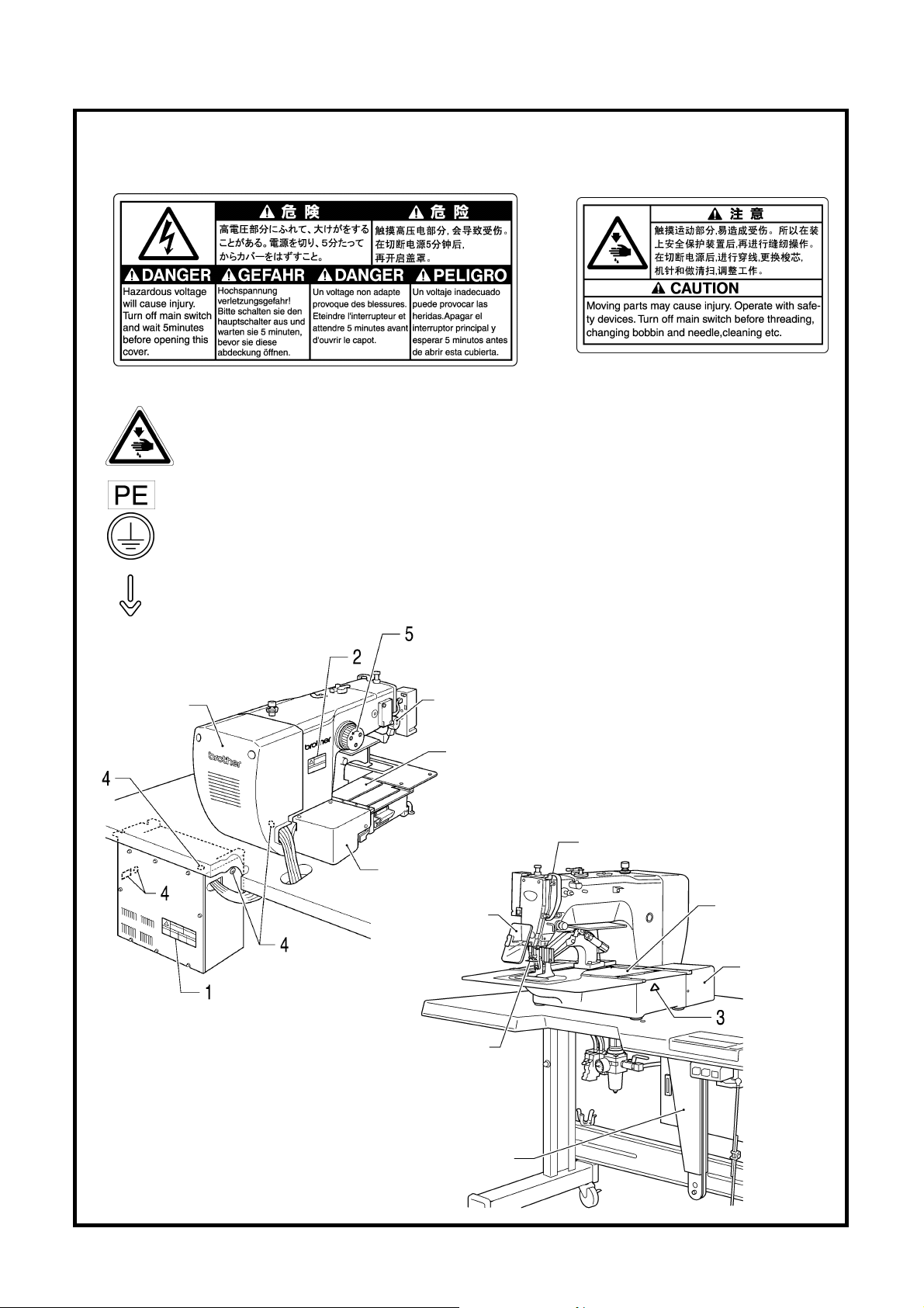
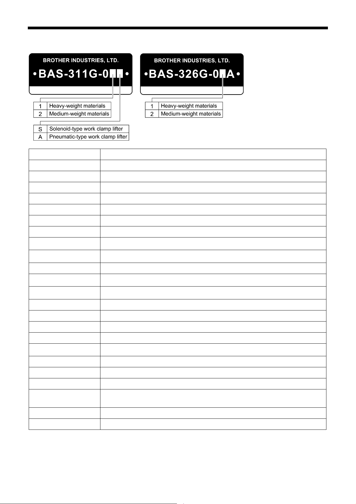
[3] Warning labels
The following warning labels appear on the sewing machine.
Please follow the instructions on the labels at all times when using the machine. If the labels have been removed or are
difficult to read, please contact your nearest Brother dealer.
1 2
3
4
5
Motor cover
Be careful not to get your hand caught when
tilting back the machine head and returning it to
its original position.
Be sure to connect the ground. If the ground
connection is not secure, you run a high risk of
receiving a serious electric shock, and problems
with correct operation may also occur.
Direction of operation
Tension release
solenoid cover
Inner cover L
Outer cover
Fixed cover L
Motor cover L
Eye guard
Finger guard
Gas spring support cover
Safety devices
Devices such as eye guard,
finger guard, thread take-up
cover, motor cover, tension
release solenoid cover, inner
cover, outer cover, fixed cover
and gas spring support cover
Thread take-up cover
Inner cover R
Outer cover
Fixed cover R
Motor cover R
5222Q
iv
4905Q
BAS-311G, BAS-326G
Page 6

CONTENTS
1. SPECIFICATIONS ............................. 1
2. FUNCTION SETTINGS...................... 2
2-1. List of special functions when power is
turned on ................................................... 2
2-2. List of advanced functions......................... 3
2-3. Memory switch setting method
(Advanced) .............................................. 4
2-4. List of memory switch settings .................. 5
2-5. Setting the work clamp mode.................... 14
2-6. Stitch counter checking method ................ 15
2-7. Error history checking method .................. 16
2-8. Input checking method .............................. 17
2-9. Output checking method ........................... 20
2-10. Software version checking method ........... 22
3. READING / WRITING DATA............. 23
3-1. Handling data ............................................ 23
3-2. Notes on handling CF cards
(sold separately) ...................................... 24
3-3. Structure of a CF card folder..................... 24
3-4. Data read/write mode................................ 25
3-5. Reading sewing data from CF cards ......... 26
3-6. Writing sewing data to CF cards ............... 27
3-7. Reading memory switch data from
CF cards.................................................... 28
3-8. Writing memory switch data to CF cards... 28
3-9. Reading user program data from
CF cards.................................................... 29
3-10. Writing user program data to CF cards ..... 29
3-11. Updating the control program.................... 30
3-12. Writing error log data to CF card ............... 31
3-13. Reading sewing data from floppy disks..... 31
3-14. Writing sewing data to floppy disks ........... 32
3-15. Reading extended option output data
from a CF card .......................................... 33
3-16. Writing extended option output data
to CF cards................................................ 34
3-17. Reading extended option output data
from floppy disks ....................................... 34
4. MECHANICAL DESCRIPTIONS ....... 35
4-1. Needle bar and thread take-up
mechanisms .............................................. 35
4-2. Lower shaft and shuttle race
mechanisms .............................................. 35
4-3. Work clamp lifter mechanism
(Solenoid specifications) .......................... 36
4-4. Work clamp lifter mechanism
(Pneumatic specifications) ....................... 37
4-5. Intermittent presser foot lifter
mechanism ................................................ 37
4-6. Intermittent presser foot stroke
mechanism ................................................ 38
4-7. Feed mechanism ....................................... 39
4-8. Thread trimmer mechanism....................... 40
4-9. Tension release mechanism...................... 41
4-10. Thread wiper mechanism .......................... 41
5. DISASSEMBLY ................................. 42
5-1. Covers ....................................................... 42
5-2. Thread wiper mechanism .......................... 43
5-3. Work clamp arm mechanism ..................... 44
5-4. Intermittent presser foot lifter
mechanism (1) ......................................... 45
5-5. Needle bar mechanism.............................. 46
5-6. Upper shaft mechanism............................. 47
5-7. Lower shaft mechanism............................. 48
5-8. Feed covers............................................... 49
5-9. Feed mechanism ....................................... 50
5-10. Work clamp lifter mechanism
(Solenoid specifications) .......................... 53
5-11. Work clamp lifter mechanism
(Pneumatic specifications) ....................... 54
5-12. Tension release mechanism...................... 55
5-13. Intermittent presser foot lifter
mechanism (2) ......................................... 55
5-14. Thread trimmer mechanism ....................... 56
5-15. Shuttle hook mechanism ........................... 57
BAS-311G, BAS-326G
Page 7

6. ASSEMBLY ......................................... 58
6-1. Thread trimmer mechanism (1) ............... 58
6-2. Intermittent presser foot lifter
mechanism (1) ......................................... 60
6-3. Tension release mechanism ..................... 60
6-4. Work clamp lifter mechanism
(Solenoid specifications) ......................... 61
6-5. Work clamp lifter mechanism
(Pneumatic specifications) ...................... 64
6-6. Feed mechanism....................................... 66
6-7. Feed covers .............................................. 73
6-8. Upper shaft mechanism ............................ 75
6-9. Needle bar mechanism ............................. 77
6-10. Intermittent presser foot lifter
mechanism (2) ......................................... 79
6-11. Lower shaft mechanism ............................ 81
6-12. Shuttle hook mechanism ........................... 83
6-13. Thread trimmer mechanism (2) ............... 83
6-14. Work clamp arm mechanism..................... 84
6-14-1. Adjustments after work clamp arm
installation ......................................... 85
6-15. Thread wiper mechanism .......................... 86
6-16. Covers....................................................... 87
7. ADJUSTMENT .................................... 88
7-1. Checking the machine head switch........... 88
7-2. Standard thread tension............................ 89
7-2-1. Upper and lower thread tension ........ 89
7-2-2. Thread take-up spring....................... 90
7-2-3. Arm thread guide R........................... 90
7-3. Adjusting the needle bar height................. 91
7-4. Adjusting the needle bar lift amount .......... 91
7-5. Adjusting the driver needle guard.............. 91
7-6. Adjusting the needle clearance ................. 92
7-7. Adjusting the shuttle race thread guide ..... 92
7-8. Rotary hook lubrication amount................. 92
7-9. Adjusting the position of the movable
knife .......................................................... 93
7-10. Replacing the movable and fixed knives ... 95
7-10-1. Installing the feed plate...................... 96
7-11. Adjusting the thread wiper ......................... 97
7-12. Presser foot installation position ................ 97
7-13. Changing the intermittent stroke................ 98
7-14. Adjusting the work clamp lift amount .........100
7-15. Adjusting the air pressure
(pneumatic specifications) .........................100
7-16. Adjusting the thread trimmer cam
position ......................................................101
7-17. Belt tension adjustment .............................101
7-18. Adjusting the tension release amount........102
7-19. Adjusting the backlash of the lower
shaft gear...................................................103
7-20. Adjusting the home position.......................104
7-20-1. Work clamp lift home position............104
7-20-2. X-Y feed home position .....................105
7-21. Adjusting the needle up stop home
position ......................................................107
7-22. Adjusting the needle up stop position ........108
8. ELECTRICAL MECHANISM ...............110
8-1. Precautions while carrying out
adjustments ...............................................110
8-2. Inside the control box and operation
panel structure...........................................111
8-3. Description of fuses ...................................112
8-4. Description of connectors ..........................113
8-4-1. Connector positions...........................113
8-4-2. Symptoms when there are poor
connections .......................................116
8-5. Troubleshooting.........................................119
8-5-1. Diagnosis flowchart ...........................119
8-5-2. Remedy .............................................123
9. TABLE OF ERROR CODES ...............137
10. TROUBLESHOOTING ......................141
11. 7-SEGMENT DISPLAY .....................144
BAS-311G, BAS-326G
Page 8
1. SPECIFICATIONS
1. SPECIFICATIONS
Sewing machine Lock stitch, pattern tacking sewing machine (with large shuttle hook)
Stitch formation Single needle lock stitch
Max. sewing speed 2,700 rpm
Sewing area (XxY) BAS-311G: Max. 130 x 100 mm, BAS-326G: Max. 220 x 100 mm
Feed mechanism Intermittent feed, pulse motor drive
Stitch length
No. of stitches 500,000-stitch internal memory (*)
Maximum no. of stitches 20,000 stitches (per program)
No. of sewing data items
that can be stored
Work clamp lift method
Work clamp height Solenoid specifications: Max. 25 mm, pneumatic specifications: Max. 30 mm
2-step work clamp
Intermittent presser foot lift
amount
Intermittent stroke
Internal memory: 512 (*), CF card: 900
Solenoid specifications: Pulse motor drive method
Pneumatic specifications: Pneumatic method
Solenoid specifications: Integrated-type work clamp
Pneumatic specifications: Separate-type work clamp
2 − 4.5 mm, 4.5 − 10 mm or 0 (Default setting 3 mm)
0.05 − 12.7 mm
22 mm
Rotary hook Double-capacity shuttle hook (standard shuttle hook sold separately)
Wiper device Standard equipment
Thread trimmer Standard equipment
Data storage method
User programs 50
Cycle programs 9
Motor 550 W AC servo motor
Weights
Power supply Single-phase 100 V/220 V, Three-phase 200 V/220 V/380 V/400 V 400 VA
Air pressure 0.5 MPa 1.8 l/min.
* The number of data items and stitches that can be stored will vary depending on the number of stitches in each program.
Internal memory (Flash memory), CF card (32, 64, 128, 256 MB)
[Option] 3.5 floppy disk 2HD/1.44MB, 2DD
Machine head approx. 88 kg, operation panel approx. 0.6 kg
Control box 14.2 − 16.2 kg (Differs depending on destination)
BAS-311G, BAS-326G
1
Page 9
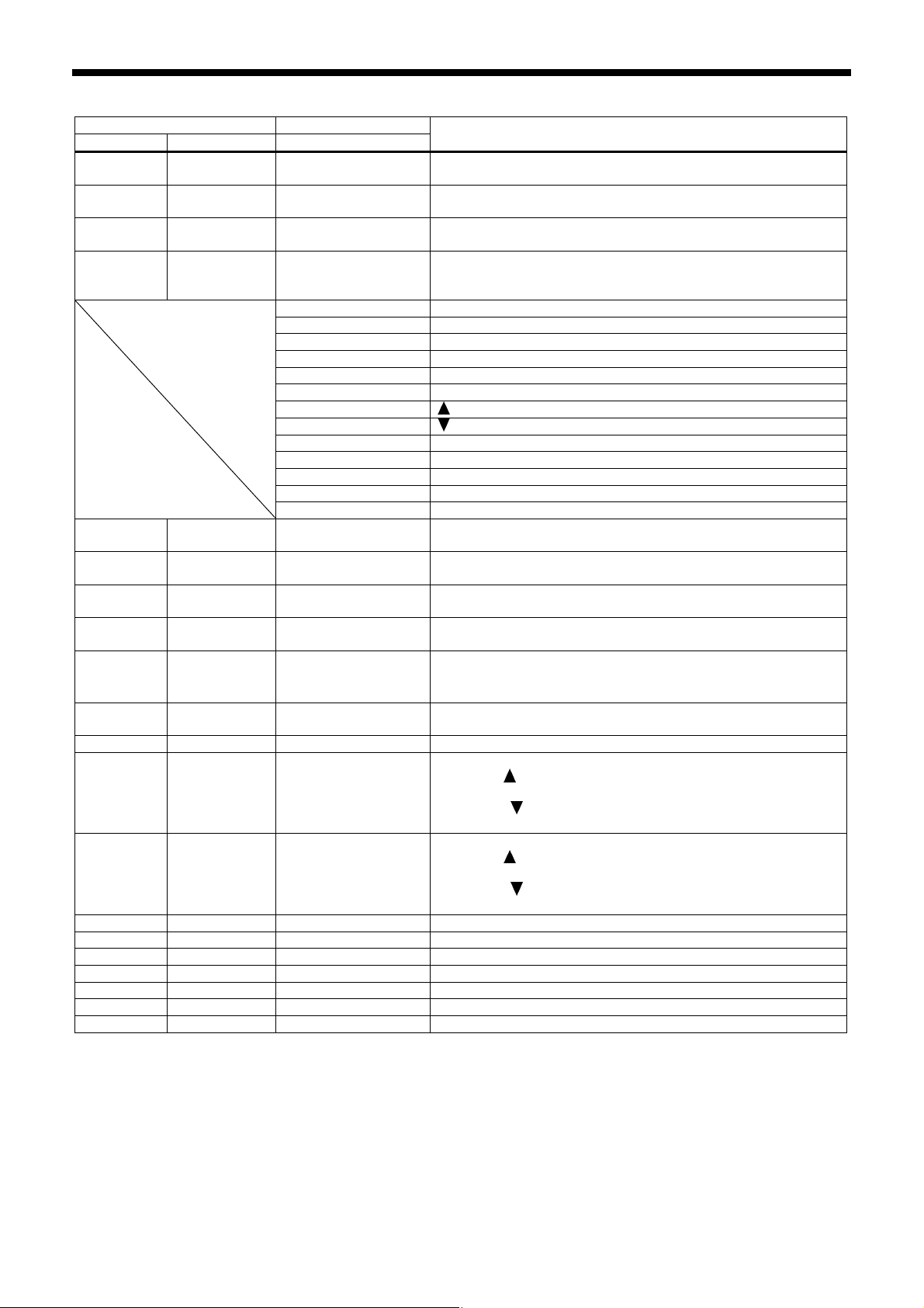
2. FUNCTION SETTINGS
2. FUNCTION SETTINGS
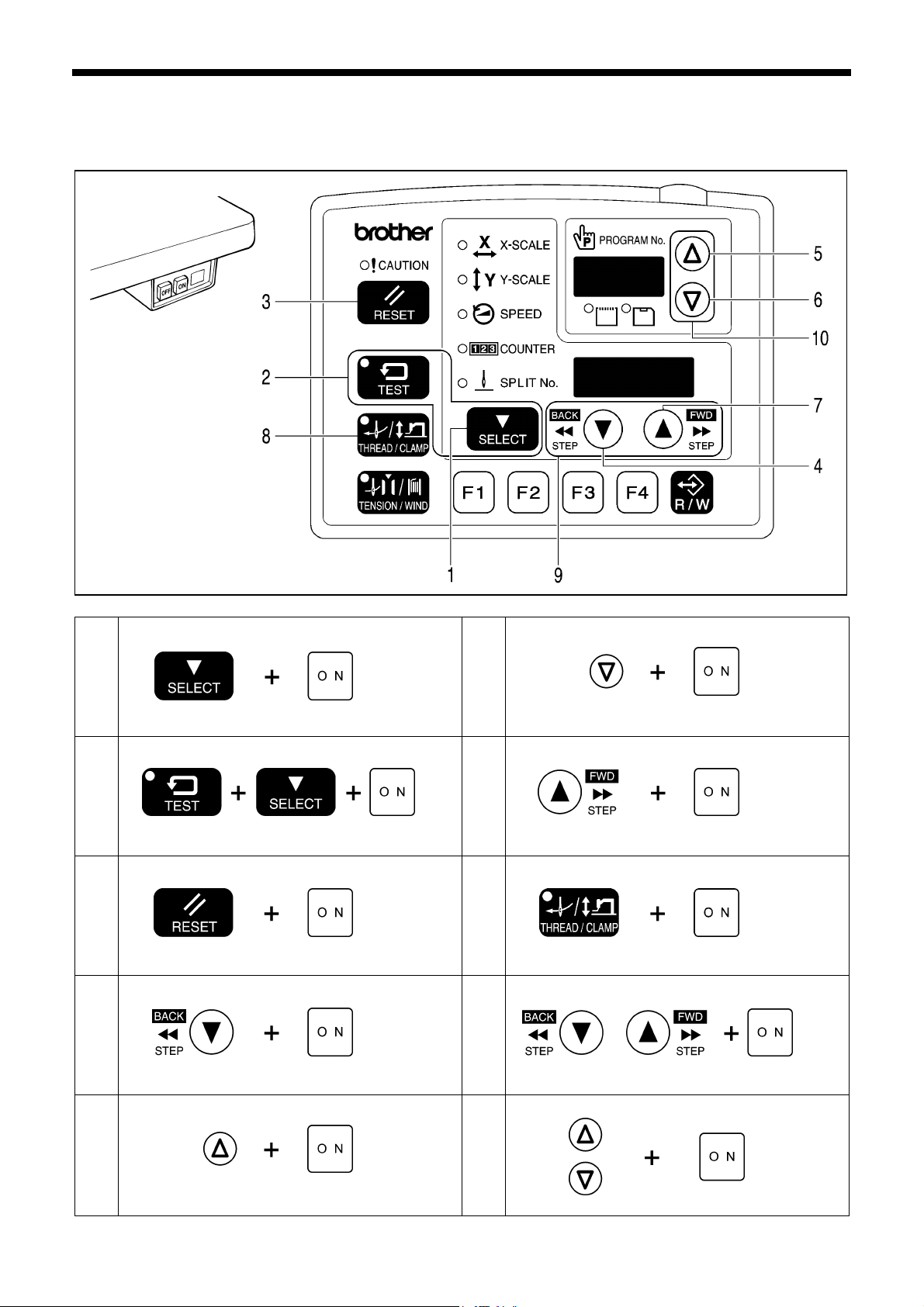
2-1. List of special functions when power is turned on
4421Q
Memory switch setting mode (Standard)
1
2
3
4
5
Refer to the Instruction Manual.
Memory switch setting mode (Advanced)
Refer to “2-3. Memory Switch Setting Method (Advanced)”.
Data initialization function
Refer to the Instruction Manual.
Error log display function
Refer to “2-7. Error history checking method”.
Input checking function
Refer to “2-8. Input checking method”.
4541Q
4543Q
4544Q
4545Q
4542Q
Output checking function
6
Refer to “2-9. Output checking method”.
Software version display function
7
Refer to “2-10. Software version checking method”.
Feed plate installation mode
8
Refer to “7-10-1. Installing the feed plate”.
Home position adjustment mode
9
Refer to “7-20. Adjusting the home position”.
Needle up stop position adjustment mode
10
Refer to “7-22. Adjusting the needle up stop position”.
5056Q
4546Q
4547Q
5057Q
4548Q
4549Q
2
BAS-311G, BAS-326G
Page 10
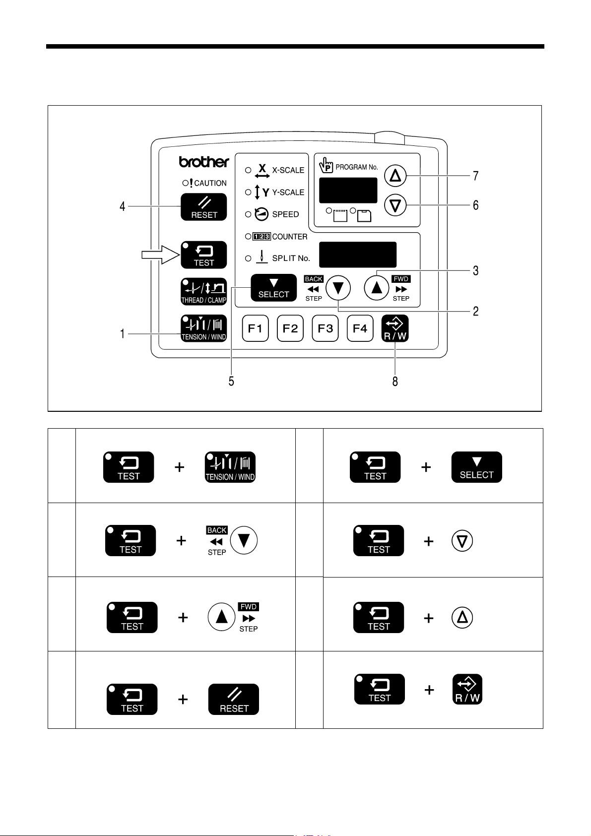
2-2. List of advanced functions
While holding down the TEST key, press the corresponding combination key.
Memory switch setting mode (Standard)
1
Refer to the Instruction Manual.
Lower thread counter setting mode
2
4489Q
4490Q
User program setting mode
5
Parallel movement mode
6
2. FUNCTION SETTINGS
4550Q
4493Q
Refer to the Instruction Manual.
4551Q
Refer to the Instruction Manual.
Production counter setting mode
3
Refer to the Instruction Manual.
Production counter temporary display function
4
When SPEED indicator is illuminated
Refer to the Instruction Manual.
4491Q
4492Q
BAS-311G, BAS-326G
Stitch counter checking mode
7
Refer to “2-6. Stitch counter checking method”.
CF data read/write mode
8
Refer to the Instruction Manual.
4552Q
4553Q
Refer to “3-4. Data read/write mode”.
3
Page 11
2. FUNCTION SETTINGS
A
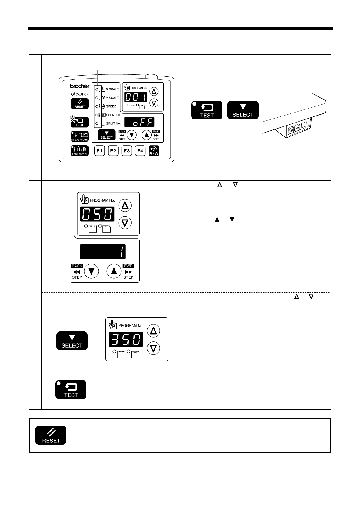
2-3. Memory switch setting method (Advanced)
1
2
If you would like to display only the numbers of
memory switches that have been changed from
default settings
Ending setting mode
3
ll indicators switch off
Menu indicator switches off
TEST indicator illuminates
TEST indicator switches off
• If you would like to return the setting for a single memory switch to the default setting, press the
RESET key while the number for that memory switch is displayed.
• To return the settings for all memory switches to the default settings, keep pressing the RESET key
for two or more seconds until the buzzer makes a long beep.
While pressing the TEST key and the SELECT key, turn
on the power switch.
* Keep pressing the TEST key and the SELECT key until
the model name is displayed and the buzzer beeps
once.
• The memory switch number will be displayed in the
PROGRAM No. display and the setting value for that
number will be displayed in the menu display.
4449Q 4421Q
Press the
number.
Press the
While pressing the SELECT key, press the or key.
• The numbers of memory switches that have been
changed from default settings will appear in order.
• If no memory switches have been changed from their
default settings, the display will not change and the
buzzer will beep twice.
Press the TEST key.
• The changes will be memorized and the sewing
machine will switch to home position detection
standby.
or key to select the memory switch
or key to change the setting value.
4554Q
4555Q
4
BAS-311G, BAS-326G
Page 12
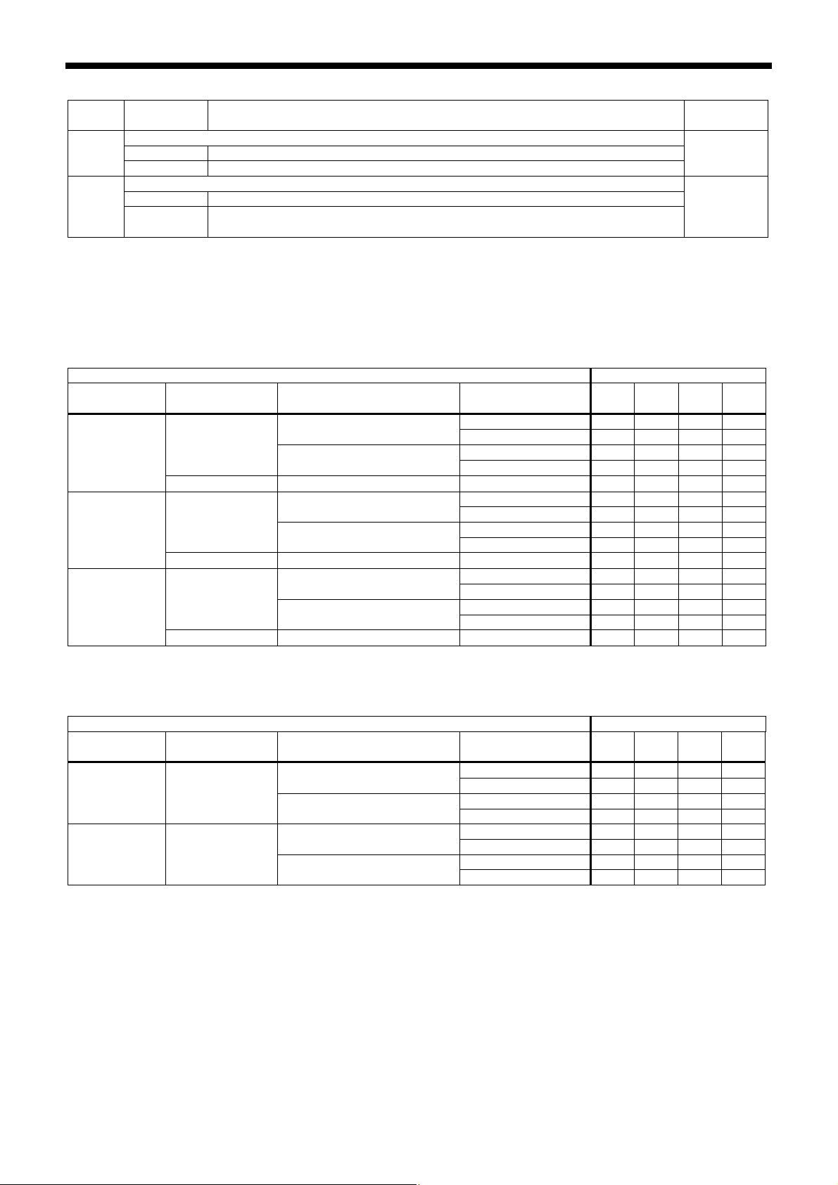
2-4. List of memory switch settings
2. FUNCTION SETTINGS
No.
001
002
003
100
200
300
400
401
402
403
*1 The mm display may differ slightly from the actual sewing size.
Setting
range
Work clamp lift timing after sewing is completed
OFF Lifts at the final stitch position.
ON Lifts after moving to the home position.
Separate-type work clamp drop operation (pneumatic specifications)
0 Left and right work clamp drop at the same time.
1
2
Work clamp drop operation (solenoid specifications)
0
1
2
Sewing start speed
OFF
ON
Single-stitch test feed
OFF
ON
Production counter display
OFF Lower thread counter display
ON Production counter display
User programs
OFF Disabled
ON User program mode is enabled.
Cycle programs
OFF Disabled
ON When sewing user programs, the set programs are sewn in numeric order.
Maximum reduction ratio (mm display) (*1)
OFF Displayed as %.
ON Displayed as mm.
Split mode selection
0 Continuous split (split menu is disabled before split detection)
1 Continuous split (split menu is always enabled)
2 Independent split
Work clamp drops in the order left → right.
Work clamp drops in the order right → left.
Analog dropping: Work clamp drops in direct proportion to the pedal depression
amount, and sewing starts when the pedal is fully depressed
1st step drop: Work clamp drops when pedal is depressed to the 1st step, and
sewing starts when pedal is depressed to the 2nd step
2nd step drop: Work clamp drops to intermediate height when the pedal is
depressed to the 1st step, and work clamp drops and sewing starts when the
pedal is depressed to the 2nd step.
The sewing speed for the first 1 − 5 stitches is set by memory switch numbers 151
− 155.
1st stitch at 400 rpm, 2nd stitch at 400 rpm, 3rd stitch at 600 rpm, 4th stitch at 900
rpm, 5th stitch at 2,000 rpm
Test feed starts when the foot switch (start switch) is depressed, and it continues
automatically until the final stitch.
Test feed is carried out one stitch at a time when the foot switch (start switch) is
depressed (feed becomes continuous if the foot switch [start switch] is
continuously depressed).
In addition, when the TEST indicator is illuminated, test feeding will move forward
one stitch at a time when the machine pulley is turned by hand.
Setting items Initial value
ON
0
2
OFF
OFF
OFF
OFF
OFF
OFF
0
BAS-311G, BAS-326G
5
Page 13
2. FUNCTION SETTINGS
Work clamp settings
No.
Setting
range
Work clamp operating mode (*2)
1 (Standard single pedal) Work clamp rises automatically.
2
3
4
5
6
7
050
8
9
10
11
Setting items Initial value
(Single pedal with no automatic work clamp lifter)
Work clamp rises in accordance with foot switch depression amount.
(Standard 2 pedal)
Work clamp rises automatically, and drops in accordance with work clamp switch
depression amount
* The left and right order can be changed using memory switch No. 002.
(2 pedal with no automatic work clamp lifter)
Work clamp lifts while work clamp switch is being depressed.
(Left/right work clamp → Intermittent presser foot 2-step work clamp)
When the work clamp switch is depressed to the 1st step, both the left and right
work clamps drop, and when it is depressed to the 2nd step, the intermittent
presser foot drops. (Lifting is in the same order.)
(Left and right alternating 2-step work clamp)
Two-step operation, with left and right order switching for each item sewn.
Starts from right → left
(Forward/reverse pedal)
When the start switch is depressed, the work clamp drops and the sewing
machine starts in that order with forward control, and when the work clamp switch
is depressed, the sewing machine reverses and the work clamp lifts.
* The left and right order can be changed using memory switch No. 002.
(2-step work clamp using two presses)
For solenoid specifications (1 pedal)
When the foot switch is depressed, the work clamp stops in the intermediate
position → work clamp drops → sewing machine starts in that order, and the work
clamp lifts when the foot switch is depressed backward.
* The work clamp does not stop in the intermediate position if memory switch No.
003 is set to “1”.
For pneumatic specifications (2 pedal)
When the work clamp switch is depressed, the left work clamp drops → right work
clamp drops → both work clamps lift in that order.
* The left and right order can be changed using memory switch No. 002.
(Standard 3 pedal)
For solenoid specifications
The left pedal lowers the work clamp in the intermediate position, the right pedal
(center) lowers the work clamp, and the start pedal (right) starts the sewing
machine.
* The work clamp does not stop in the intermediate position if memory switch No.
003 is set to “1”.
For pneumatic specifications
The left pedal raises and lowers the left work clamp, and the right pedal (center)
raises and lowers the right work clamp.
The start pedal (right) starts the sewing machine.
(Triple pedal with independent home detection)
The right pedal (center) is used exclusively for detecting the home position.
The left pedal raises and lowers the left and right work clamps, and the start pedal
(right) starts the sewing machine.
(Special triple pedal with independent home detection)
The right pedal (center) is used exclusively for detecting the home position.
The left pedal raises and lowers the left work clamp, and the start pedal (right)
lowers the right work clamp and starts the sewing machine.
*3
*2 Allowable setting values by specification
Pedal specifications Solenoid specifications Pneumatic specifications
1 pedal 1, 2, 8 1, 2
2 pedal 3, 4 3, 4, 5, 6, 7, 8
3 pedal 9 9, 10, 11
*3 Solenoid specifications: 1, Pneumatic specifications: 3
6
BAS-311G, BAS-326G
Page 14

2. FUNCTION SETTINGS
No.
Setting
range
Setting items Initial value
Work clamp operation before home position detection
051
OFF Work clamp cannot be raised or lowered before home position is detected
ON
ON Work clamp can be raised and lowered before home position is detected
Work clamp operation during split programs
052
053
OFF Work clamp lifts automatically when sewing pauses due to a split program
ON
Work clamp lifts when the foot switch is depressed when sewing pauses due to a
split program
Time from intermittent presser foot lifting until feed mechanism starts moving
0 − 999
Units (mS)
OFF
100
Intermittent presser foot drop timing
Presser foot drops when the work clamp switch is depressed, but it does not drop
at the feed retract position.
Presser foot drops at the sewing start, regardless of the work clamp switch
operation.
0
054
0
1 Presser foot drops when the work clamp switch is depressed.
2
Work clamp signal valve special output for pneumatic-type work clamp (pneumatic specifications)
0 Disabled
Valve output is reversed for pneumatic specifications
055
1
(Connect the air tubes in reverse so that the work clamp can lift when the power is
turned off.)
0
Reverse valve output is output simultaneously for 2-position valve specifications.
2
(Right work clamp reverse = Option output No. 4, Left work clamp reverse =
Option output No. 5)
Thread winding operation before home position is detected
056
OFF Thread winding cannot be carried out before home position is detected.
OFF
ON Thread winding can be carried out before home position is detected.
Work clamp operation when feed moves to sewing start position after home position is detected
Work clamp stays dropped after home position is detected
057
OFF
ON
Work clamp lifts when pedal is depressed backward (for single pedal) or when
work clamp switch is depressed (for 2 pedals)
Work clamp lifts automatically after home position is detected.
* Disabled when memory switch No. 050 = 2 or 4.
ON
Work clamp operation at sewing end
058
OFF
Work clamp lifts automatically at the sewing end
* Disabled when memory switch No. 050 = 2 or 4.
OFF
ON Work clamp does not lift automatically at the sewing end
BAS-311G, BAS-326G
7
Page 15
2. FUNCTION SETTINGS
Sewing machine motor settings
No.
Setting
range
Setting items Initial value
Highest needle position stop
OFF Disabled
When the upper shaft stops, the motor operates in reverse to return the needle bar
150
ON
close to its highest position.
(When the motor operates in reverse to raise the needle, the thread take-up will
stop at a position which is lower than its normal stopping position. As a result, the
OFF
thread take-up will rise slightly at the sewing start, and this may result in the thread
pulling out under certain conditions.)
151
152
153
154
155
156
157
158
159
1st stitch sewing speed at the sewing start
4 − 27
(Units x100 rpm)
2nd stitch sewing speed at the sewing start
4 − 27
(Units x100 rpm)
3rd stitch sewing speed at the sewing start
4 − 27
(Units x100 rpm)
4th stitch sewing speed at the sewing start
4 − 27
(Units x100 rpm)
5th stitch sewing speed at the sewing start
4 − 27
(Units x100 rpm)
5th last stitch sewing speed at the sewing end
4 − 27
(Units x100 rpm)
4th last stitch sewing speed at the sewing end
4 − 27
(Units x100 rpm)
3rd last stitch sewing speed at the sewing end
4 − 27
(Units x100 rpm)
2nd last stitch sewing speed at the sewing end
4 − 20
(Units x100 rpm)
4
8
12
27
27
27
27
27
12
Piercing force boosting operation
161
OFF Disabled
ON
Piercing force boosting operations are carried out when the sewing machine motor
is locked
OFF
Regulation of sewing speed changes due to sewing pitch changes
OFF Sewing speed varies depending on sewing pitch of the sewing data
162
ON
Speed is fixed at the minimum sewing speed for the maximum pitch of the sewing
data
(Set to ON if there may be a problem with sewing speed changes as a result of
OFF
pitch changes.)
163
Limits the maximum sewing speed.
12 − 27
(Units x100 rpm)
27
Thread trimming disabled
164
OFF Thread trimming is carried out in accordance with the sewing data.
OFF
ON All thread trimming operations are disabled.
Highest needle position stop angle (Units 2 degree steps) (*4)
165
-15 − 0
0: Normal needle up position: Needle bar height increases for values in the
negative direction.
0
*4 If the setting value becomes to large in the negative direction, error “E110” may be generated at the first sewing start
after the power is turned on.
8
BAS-311G, BAS-326G
Page 16
Feed settings
No.
Mechanism home position return when sewing is finished
250
Feed speed
251
High-speed test feeding
252
Home position detection method
253
Movement path from mechanism home position to start position
254
260
261
262
263
264
265
266
Changes the overall feed timing
-10 − 10 -10: Early ← 0: Standard → 10: Late
Changes the feed timing for the 1st stitch at the sewing start
-10 − 10 -10: Early ← 0: Standard → 10: Late
Changes the feed timing for the 2nd stitch at the sewing start
-10 − 10 -10: Early ← 0: Standard → 10: Late
Changes the feed timing for the 3rd stitch at the sewing start
-10 − 10 -10: Early ← 0: Standard → 10: Late
Changes the feed timing for the 3rd stitch before the sewing end
-10 − 10 -10: Early ← 0: Standard → 10: Late
Changes the feed timing for the 2nd stitch before the sewing end
-10 − 10 -10: Early ← 0: Standard → 10: Late
Changes the feed timing for the 1st stitch before the sewing end
-10 − 10 -10: Early ← 0: Standard → 10: Late
If the overall feed timing (setting for No. 260) is changed from the default value, specify the
number of applicable stitches.
267
Changes feed timing standard
268
269
Adjusts the feed motor output
2. FUNCTION SETTINGS
Setting
range
Setting items Initial value
OFF When sewing is finished, the feed plate returns to the start position.
ON
When sewing is finished, the feed plate moves via the machine home position to
the start position.
1 100 mm/s Slow
2 200 mm/s
3 300 mm/s
4 400 mm/s
5 500 mm/s Fast
Feeding is normally slow, and becomes faster when the foot switch is depressed
OFF
to the 1st step
(For 2 pedals, it becomes faster when the work clamp switch is depressed.)
ON
Test feeding is at the same speed as sewing.
* This does not apply to checking stitch by stitch.
OFF Depress the foot switch (start switch) while the PROGRAM No. display is flashing.
ON
0
1
2
3
Press the special external input switch (EXIN3) while the PROGRAM No. display
is flashing. (Foot switch/start switch are disabled.)
Moves to the start position simultaneously for X and Y, in the order of in front of Y
→ middle of X.
Moves to start position in the order of X start point → Y start point in the order of in
front of Y → middle of X.
Moves to start position in the order of right edge of X → Y start point → X start
point in the order of right edge of X → in front of Y.
Moves to start position in the order of left edge of X → Y start point → X start point
in the order of left edge of X → in front of Y.
0 No limit
1 − 99
The feed timing returns to the standard feed timing once the specified number of
stitches has been sewn.
0 [Feed start reference] Makes the timing uniform at the start of feed.
1
[Needle up reference] Changes the timing at the start of feed so that the needle
zigzagging is even.
2 [Feed end reference] Makes the timing uniform at the end of feed.
3 [Linked to speed] Feed timing is uniform even if the sewing speed changes.
-5 − 5 -5: Low← 0: Standard → 5: High
OFF
3
OFF
OFF
0
0
0
0
0
0
0
0
0
1
0
BAS-311G, BAS-326G
9
Page 17
2. FUNCTION SETTINGS
Operation panel settings
No.
Setting
range
Operation panel changing limitation
0 No limits on changing setting values using the operation panel.
1
350
2
3 Program numbers cannot be changed.
4 Program numbers and XY scale settings cannot be changed.
5 Program numbers, XY scale and sewing speed settings cannot be changed.
6 XY scale settings cannot be enlarged. (They can be reduced.)
7 Sewing speed setting cannot be changed.
Changing memory switches
351
OFF Allowed
ON Forbidden
Counting method for lower thread counter and production counter
352
0 Counted for each item of sewing data
1 Counted for each thread trimming operation.
2 Counted when sewing data ends or when split stops
Counter timing for lower thread counter
353
OFF Counted at the end of sewing.
ON Counted at the start of sewing.
Switching program numbers using an external switch
0 Disabled
354
1 − 9
Switches split numbers using an external switch
355
OFF Disabled
ON
Setting items Initial value
Program numbers, XY scale, sewing speed, lower thread counter, work clamp
height, intermittent height and digital tension values cannot be changed.
Program numbers, XY scale, sewing speed, work clamp height, intermittent height
and digital tension values cannot be changed.
Program number is switched by means of the 5 bits of option input (EXIN6 −
EXIN10).
Applicable numbers are: Setting number = 3rd digit, last two digits can be 1 − 31.
Split number is switched by means of the 5 bits of option input (EXIN6 − EXIN10).
Applicable numbers are 1 − 31 (only enabled for independent split mode)
0
OFF
0
OFF
0
OFF
User program settings
No.
Setting
range
Moving to start point when switching user programs
450
OFF Feed moves to the start point after starting and switching.
ON
Limitations on changing settings for user programs
452
OFF No limit
ON User program contents cannot be changed.
Setting items Initial value
Feed moves to the next sewing start point at the same time as the user program
switches.
OFF
OFF
10
BAS-311G, BAS-326G
Page 18
Data editing settings
No.
Setting
range
Sewing area limit in X direction [Units mm]
460
0 − 130
0 − 220
461
Sewing area limit in Y direction
0 − 100
Enlargement/reduction reference point
462
0 Center of sewing frame
1 Sewing start point
2 Center of pattern
Enlargement/reduction for bar tacking
463
OFF Bar tacking stitches (pitch approx. 1 mm or less) cannot be enlarged or reduced.
ON Bar tacking stitches (pitch approx. 1 mm or less) are also enlarged or reduced.
Enlargement/reduction ratio in XY directions
464
OFF Disabled
ON
Storing parallel movement amount for sewing pattern
465
OFF
ON
Reading sewing data from eternal media into internal memory
0 [Normal mode] Programs are copied one by one into internal memory.
1
466
2
Changing gear ratio correction method when reading from a 2DD floppy disk.
0
467
1 BAS-311A data is read.
2 BAS-326A data is read.
3 BAS-341A/BAS-342A data is read.
Retract point switching at parallel movement point
468
OFF Disabled
ON The position moved to by parallel movement is recorded as the retract point.
2. FUNCTION SETTINGS
Setting items Initial value
BAS-311G setting value 130
BAS-326G setting value 220
[Units mm] 100
0
OFF
Enlargement/reduction ratio setting is the same for X and Y
OFF
(Disabled for user programs)
Initialized when program number or enlargement/reduction ratio is changed and
when power is turned off.
OFF
Initialized when program number or enlargement/reduction ratio is changed but not
when power is turned off.
[Overwrite mode] Sewing data is overwritten into the temporary buffer area.
If sewing data with the same program number already exists in internal memory, it
is deleted.
[Assignment mode] Sewing data is overwritten into the temporary buffer area.
0
If sewing data with the same program number already exists in internal memory, it
is not deleted, but only the data in the temporary buffer is used.
(If sewing data with the same program number already exists in internal memory
and the setting is changed to “0” or “1”, the data in the temporary buffer will be
cleared.)
Automatic conversion as specified by sewing machine model.
(For the BAS-311G, data is read as BAS-311A data and then converted.)
0
OFF
Device settings
No.
Setting
range
Needle cooler device
550
OFF Disabled
ON Needle cooler device is used. (Option output No. 12)
Tension release setting at the sewing start
551
OFF Disabled
ON Enabled
552
553
Tension release timing during thread trimming [Units 8 degree steps]
-10 − 1 -10: Early ← 0: Standard → 1: Late
Thread nipping timing (*5)
1 − 4 1: Early ← 2: Standard → 4: Late
*5 Not used for the BAS-311G and BAS-326G.
Setting items Initial value
BAS-311G, BAS-326G
OFF
OFF
0
2
11
Page 19
2. FUNCTION SETTINGS
No.
Setting
range
Thread breakage detector
554
OFF Disabled
ON Fiber-type thread breakage detector used
Thread breakage detector detection sensitivity
555
OFF 5 stitches at sewing start, 3 stitches while sewing
ON 10 stitches at sewing start, 3 stitches while sewing
Inner clamping device (Option output No. 13)
0 Disabled
Inner clamping device is used.
1
556
(Retract operation is carried out at the sewing end to prevent interference with the
needle.)
2 Inner clamping device is used. (No retract operation at the sewing end.)
Inner clamping device operates for 1/4 of the sewing pattern and returns for the
3
other 3/4.
(No retract operation)
External wiper device
557
0 Disabled
1 Solenoid-type wiper device is used.
2 Pneumatic-type wiper device is used. (Option output No. 2)
External error monitoring input
558
OFF Disabled
ON Enabled (P10, option input No. 13 [AIRSW])
Operating indicator output
OFF Disabled
559
ON
Option output No. 9: Output ON while operating
Option output No. 10: ON during lower thread conversion and during test mode
Option output No. 11: ON when error is generated
Automatic ejector (Option output No. 3 output, option input No. 1 = right sensor, input No. 2 = left
sensor) [Pneumatic specifications]
560
0 Disabled
1 Standard operation
2 Sewing starts when cassette sensor is ON
3 Start switch is enabled even if cassette sensor is OFF.
Timer from sensor detection to sewing start when automatic ejector automatic starting is set
561
(memory switch No. 560 = 2) [Pneumatic specifications]
0 − 999
Time from after the cassette is chucked until automatic starting
Changes the digital tension setting value.
562
OFF Tension number can be changed regardless of the sewing data.
ON
Only tension No. 0 and the tension numbers detected in the sewing data can be
changed.
2-step tension is possible (When using spring-type main tension)
563
OFF Disabled
ON 2-step tension is used.
Increases maximum tension release force when using a spring-type main tension
0 Disabled (Tension release is open at the sewing end.)
564
1
2
Increases the force (Tension release is closed at the sewing end. If tension release
is open, it will be closed in approximately 5 minutes.)
Increases force to the maximum. (Tension release is closed at the sewing end. If
tension release is open, it will be closed in approximately 1 minute.)
Thread nipper device (*6)
565
OFF Disabled
ON
Thread nipper device installed (Memory switch No. 500 must also be set to ON or
OFF.)
*6 Not used for the BAS-311G and BAS-326G.
Setting items Initial value
OFF
OFF
0
1
OFF
OFF
0
100
ON
OFF
0
OFF
12
BAS-311G, BAS-326G
Page 20
Error processing settings
No.
Setting
range
Error release method when operation has stopped
650
0 Press the RESET key.
1 Press the RESET key or the STOP switch.
2 Press the RESET key or input a signal from the external switch (EXIN3).
Needle stop position when sewing is interrupted by the STOP switch
651
0 Needle stops in the down position.
1 Needle stops in the up position.
2 Needle stops in the up position after thread trimming.
Thread trimming operation when sewing is paused
652
OFF Thread trimming is carried out when the pause is canceled.
ON Thread trimming is not carried out when the pause is canceled.
Resuming sewing after sewing is paused
653
OFF
ON
STOP switch → RESET key →
STOP switch → RESET key → Sewing starts
Disables the needle up stop position monitoring sensor
655
OFF Sensor is enabled and needle up stop position errors [E110] are detected.
ON Disabled
Home position return when sewing is paused
656
OFF Mechanism moves to home position and then moves to sewing start position.
ON
Mechanism steps back to the sewing start position along the sewing path without
moving to the home position.
2. FUNCTION SETTINGS
Setting items Initial value
0
0
OFF
key → Sewing starts
OFF
OFF
OFF
Maintenance settings
No.
Setting
range
Run-in operation mode
0 Disabled
While the foot switch is being depressed, the work clamp moves up and down
1
once and then continuous operation starts.
(Work clamp does not move up or down if memory switch No. 050 = 2 or 4)
750
2
While the foot switch is being depressed, the work clamp moves up and down
twice and then continuous operation starts.
(Work clamp does not move up or down if memory switch No. 050 = 2 or 4)
While the foot switch is being depressed, the work clamp moves up and down
3
three times and then continuous operation starts.
(Work clamp does not move up or down if memory switch No. 050 = 2 or 4)
751
752
Run-in operation cycle time adjustment timer
0 − 255
00 − 99
Units [x10 ms]
Sewing machine ID code
Sewing data specified on CF card
Reading/writing sewing data for old models
755
OFF Only compatible with floppy disks.
ON Reading and writing using CF cards is possible in data read/write mode.
Main shaft angle display mode
756
OFF Disabled
ON Main shaft angle is displayed when sewing machine starts.
Specifications and destination settings
No.
Setting
range
Specification code setting
(This memory switch does not return to the initial value when all settings are reset.)
Specifications at the time of shipment from the factory
(Specifications shown on the model plate on the machine head)
850
0
1 Heavy-weight material specifications
2 Medium-weight material specifications
3 Extra heavy-weight material specifications
Setting items Initial value
0
20
00
OFF
OFF
Setting items Initial value
0
BAS-311G, BAS-326G
13
Page 21
2. FUNCTION SETTINGS
Unique machine settings
No.
950
951
Setting
range
Automatic start for extended option output No. 1
OFF Disabled
ON Sewing machine starts when extended option output No. 1 is ON.
Program number output
OFF Disabled
ON
When the last two digits of the program number are 1 to 15, the program number
is output in 4 bits to extended option output 4 − 7.
Setting items Initial value
OFF
OFF
2-5. Setting the work clamp mode
Combinations of memory switch settings can be used to switch the work clamp operating mode to any one of the following
modes.
<Solenoid specifications, single pedal standard operations>
Operating mode Memory switch setting
Drop operation
Analog drop
1st step drop
2nd step drop
(*) If memory switch No. 057 is OFF, the work clamp will lift when the pedal is depressed backward.
<Solenoid specifications, single pedal sequence operation>
Drop operation
1st step drop Yes
2nd step drop Yes
(*) Work clamp lifts when pedal is depressed backward.
Automatic work
clamp lifting
Yes
No Dropped (*) Dropped (*) 0 2
Yes
No Dropped (*) Dropped (*) 1 2
Yes
No Dropped (*) Dropped (*) 2 2
Automatic work
clamp lifting
After home position detection After sewing start 003 050 057 058
Automatic lift
Dropped (*)
Automatic lift
Dropped (*)
Automatic lift
Dropped (*)
Operating mode Memory switch setting
After home position detection After sewing start 003 050 057 058
Automatic lift
Dropped (*)
Automatic lift
Dropped (*)
Automatic lift 0 1 ON OFF
Dropped 0 1 ON ON
Automatic lift 0 1 OFF OFF
Dropped (*) 0 1 OFF ON
Automatic lift 1 1 ON OFF
Dropped 1 1 ON ON
Automatic lift 1 1 OFF OFF
Dropped (*) 1 1 OFF ON
Automatic lift 2 1 ON OFF
Dropped 2 1 ON ON
Automatic lift 2 1 OFF OFF
Dropped (*) 2 1 OFF ON
Automatic lift 1 8 ON OFF
Dropped (*) 1 8 ON ON
Automatic lift 1 8 OFF OFF
Dropped (*) 1 8 OFF ON
Automatic lift 2 8 ON OFF
Dropped (*) 2 8 ON ON
Automatic lift 2 8 OFF OFF
Dropped (*) 2 8 OFF ON
− −
− −
− −
14
BAS-311G, BAS-326G
Page 22
<Pneumatic specifications, 2 pedal standard operations>
Operating mode Memory switch setting
Work clamp operation
Work clamp lifts automatically
and drops when the work
clamp switch is depressed.
After home position
detection
Automatic lift
Dropped
After sewing start 002 050 057 058
Automatic lift 3 ON OFF
Automatic lift 3 OFF OFF
2. FUNCTION SETTINGS
Work clamp drop
Dropped 3 ON ON
Dropped
sequence selection
0: Left and right
simultaneously
1: Left → Right
2: Right → Left
3 OFF ON
Work clamp rises while work
clamp switch is depressed
Work clamp switch
1st step: Both left and right
work clamps drop
2nd step: Intermittent presser
foot drops
Lifting is simultaneous
Work clamp drop sequence at
work clamp switch 1st and
2nd steps alternates each
time an article is sewn.
Initially right → left
<Pneumatic specifications, 2 pedal sequence operation>
Operating mode Memory switch setting
Work clamp operation
When start switch is
depressed, work clamp drops
→ sewing starts
Lifts in reverse order using
work clamp switch
Work clamp switch
Left (right) work clamp →
Right (left) work clamp →
Both work clamps lift
Dropped Dropped
Automatic lift
Dropped
Automatic lift
Dropped
After home position
detection
Automatic lift
Dropped
Automatic lift
Dropped
Automatic lift 5 ON OFF
Automatic lift 5 OFF OFF
Automatic lift 6 ON OFF
Automatic lift 6 OFF OFF
After sewing start 002 050 057 058
Automatic lift 7 ON OFF
Automatic lift 7 OFF OFF
Automatic lift 5 ON OFF
Automatic lift 5 OFF OFF
−
Dropped 5 ON ON
Dropped
Dropped 6 ON ON
Dropped
Work clamp drop
Dropped 7 ON ON
Dropped
Dropped 5 ON ON
Dropped
sequence selection
0: Left and right
simultaneously
1: Left → Right
2: Right → Left
Work clamp drop
sequence selection
0: Left and right
simultaneously
1: Left → Right
2: Right → Left
−
−
4
5 OFF ON
6 OFF ON
7 OFF ON
5 OFF ON
− −
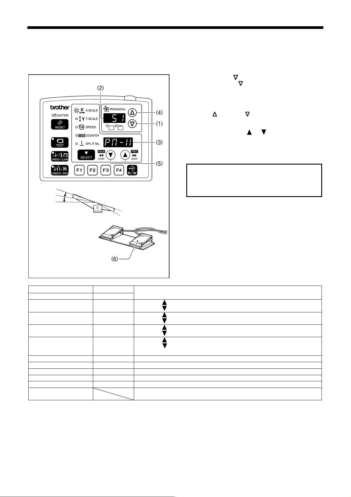
2-6. Stitch counter checking method
5058Q
BAS-311G, BAS-326G
1. While holding down the TEST key (1), press the key
(2).
“Cnt” will be displayed in the PROGRAM No. display (3),
and the cumulative number of stitches will be displayed
in the menu display (4) in units of 100,000 stitches.
(While the key (5) is being pressed, the cumulative
number of stitches will be displayed in units of 100
stitches in all 7 digits of the PROGRAM No. display and
the menu display (4).)
2. When the TEST key (1) is pressed, the display will
return to the normal display.
<Clearing the cumulative number of stitches>
1. When “Cnt” is displayed, press the
cumulative number of stitches will change to “0000” and
the display will flash.
2. Press the RESET key (7) for two seconds or more. (The
cumulative number of stitches “0000” will stop flashing
and illuminate, and the setting will be cleared. )
3. When the TEST key (1) is pressed, the display will
return to the normal display.
key (6). The
15
Page 23
2. FUNCTION SETTINGS
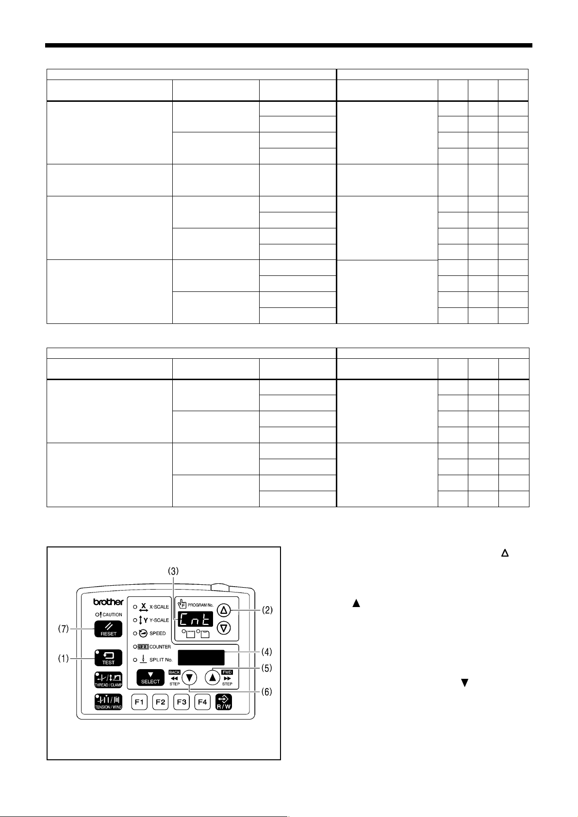
2-7. Error history checking method
The past error history can be checked by the following procedure.
TEST indicator illuminates, Menu indicator switches off
1. While pressing the
* Keep pressing the key (1) until the model name is displayed and the buzzer beeps once.
The error history sequence number will be displayed in the PROGRAM No. display (2) and the error code will be
displayed in the menu display (3).
2. Press the or key (4) to switch the error history sequentially.
3. When the TEST key (5) is pressed, the display will return to the normal display and the sewing machine will change to
home position standby.
<Display example>
If there is no error history [000]
Error [E110] is displayed first. [001] [E110]
• While the key (6) is being pressed, the COUNTER indicator will illuminate and the stitch number counter value at the
point where the error occurred will be displayed in the PROGRAM No. display (2) and the menu display (3) in units of 100
stitches.
key (1), turn on the power switch.
Details PROGRAM No. display (2) Menu display (3)
[E − − −]
4564Q
16
BAS-311G, BAS-326G
Page 24
2. FUNCTION SETTINGS
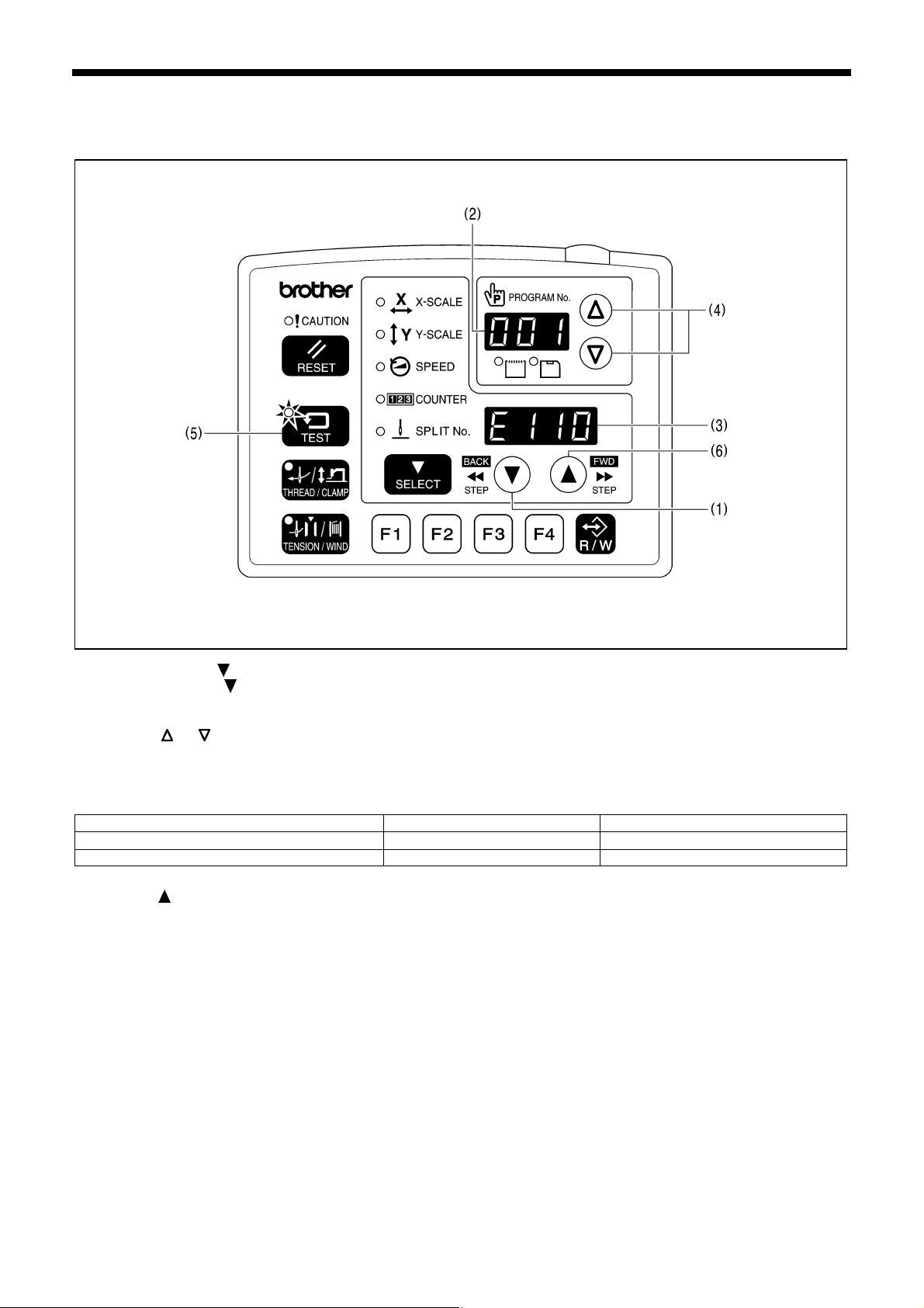
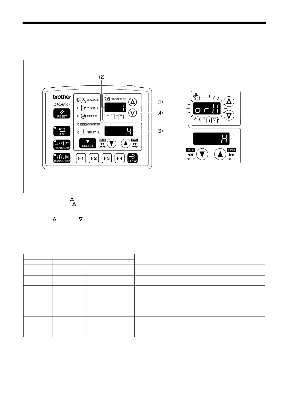
2-8. Input checking method
Use this to check for any malfunctions of the operation panel keys, circuit boards or sensors, and for checking for broken
cords and for adjusting sensor positions.
You can check whether the CPU is correctly reading the signals from keys and sensors.
4565Q
1. While pressing the
key (1), turn on the power switch.
* Keep pressing the key (1) until the model name is displayed and the buzzer beeps once.
The check code will be displayed in the PROGRAM No. display (2), and the input status will be displayed in the menu
display (3).
2. Press the key (1) or key (4) to select the desired check code.
If no operations are carried out for 5 seconds after a check code has been selected, the check code and the
abbreviated input name will flash alternately in the PROGRAM No. display (2).
3. Refer to the input check list for key and sensor responses.
4. To return to normal operation, turn off the power switch and then turn it back on again.
<Input check list>
PROGRAM No. display Menu display
Check code Name Input status
[ 1] [orX] [ H] / [ L]
[ 2] [EnX]
[-999] − [999]
[ 3] [orY] [ H] / [ L]
[ 4] [EnY]
[-999] − [999]
[ 5] [orP] [ H] / [ L]
[ 6] [EnP]
[ 7] [Enn]
[-999] − [999]
[ 0] − [180]
X-axis motor home position sensor signal
Move the feed mechanism by hand in the X direction.
X-axis motor encoder counter value
Move the feed mechanism by hand in the X direction.
Y-axis motor home position sensor signal
Move the feed mechanism by hand in the Y direction.
Y-axis motor encoder counter value
Move the feed mechanism by hand in the Y direction.
Work clamp motor home position sensor signal
Raise the work clamp by hand.
Work clamp motor encoder counter value
Raise the work clamp by hand.
Upper shaft 180 degree rotation signal
Turn the pulley by hand.
Check item and checking method
4566Q
BAS-311G, BAS-326G
17
Page 25
2. FUNCTION SETTINGS
PROGRAM No. display Menu display
Check code Name Input status
[ 8] [ UP] [ on] / [ oFF]
[ 9] [ dn] [ on] / [ oFF]
[ 10] [voL]
[ 0] − [ 300]
Needle up signal
Turn the pulley by hand.
Needle drop signal
Turn the pulley by hand.
Power supply voltage
Displayed as %
Check item and checking method
Operation panel input check
[ 11] [PnL] [*] / [ oFF]
While a key is being pressed, the name of the key will be
displayed.
*ON display Key name
[rESt] RESET key
[tESt] TEST key
[tHrE] THREAD/CLAMP key
[ tEn] TENSION/WIND key
[SELE] SELECT key
[UP-M] key
[dn-M] key
[ F1] Function key F1
[ F2] Function key F2
[ F3] Function key F3
[ F4] Function key F4
[ CF] R/W key
[ 12] [FtA]
[ 0] − [ 255]
[ 13] [CL1] [ on] / [ oFF]
[ 14] [CL2] [ on] / [ oFF]
[ 15] [Stt] [ on] / [ oFF]
[− − on]
[ 16] [EMC]
[on − −]
Foot switch analog value (Single pedal specifications)
Depress the foot switch.
Work clamp 1st step (2 pedal specifications)
Depress the foot switch to the 1st step.
Work clamp 2nd step (2 pedal specifications)
Depress the foot switch to the 2nd step.
Start switch (2 pedal specifications)
Depress the foot switch to the 2nd step.
STOP switch
Press the STOP switch.
[− − − −]
[ 17] [HEd] [ on] / [ oFF]
Machine head switch
Tilt back the machine head.
[ 18] [EXE] [ on] / [ oFF] External input error detection (IN13)
Thread nipper hope position sensor (IN14) (*1)
key to move the thread nipper in the home position
key to move the thread nipper in the retract
[ 19] [CAH] [ on] / [ oFF]
Press the
direction.
Press the
direction.
Thread nipper retract sensor (IN15) (*1)
Press the key to move the thread nipper in the home position
[ 20] [rEL] [ on] / [ oFF]
direction.
Press the
key to move the thread nipper in the retract
direction.
[ 21] [in1] [ on] / [ oFF] Option input (IN1)
[ 22] [in2] [ on] / [ oFF] Option input (IN2)
[ 23] [in3] [ on] / [ oFF] Option input (IN3)
[ 24] [in4] [ on] / [ oFF] Option input (IN4)
[ 25] [in5] [ on] / [ oFF] Option input (IN5)
[ 26] [rot] [ on] / [ oFF] Option input (IN11)
[ 27] [Fib] [ on] / [ oFF] Fiber-type thread breakage detection [Option compatibility]
*1 Not used for the BAS-311G and BAS-326G.
18
BAS-311G, BAS-326G
Page 26

PROGRAM No. display Menu display
Check code Name
Input status
Check item and checking method
[ 28] [Por] [ on] / [ oFF] Work clamp home position sensor
[ 29] [Xor] [ on] / [ oFF] X-feed home position sensor
[ 30] [Yor] [ on] / [ oFF] Y-feed home position sensor
[ 31] [in6] [ on] / [ oFF] Option input (IN6)
[ 32] [in7] [ on] / [ oFF] Option input (IN7)
[ 33] [in8] [ on] / [ oFF] Option input (IN8)
[ 34] [in9] [ on] / [ oFF] Option input (IN9)
[ 35] [in10] [ on] / [ oFF] Option input (IN10)
2. FUNCTION SETTINGS
BAS-311G, BAS-326G
19
Page 27
2. FUNCTION SETTINGS
2-9. Output checking method
Use this to check for any malfunctions of the circuit boards, and for checking for problems with drive mechanisms and
broken cords.
You can check whether the signals being output by the CPU are driving the mechanisms correctly.
4567Q
1. While pressing the
* Keep pressing the key (1) until the model name is
displayed and the buzzer beeps once.
The check code will be displayed in the PROGRAM No.
display (2), and the abbreviated name of the output will
be displayed in the menu display (3).
2. Press the key (4) or key (1) to select the desired
check code.
3. The operations for check codes 51 to 54 can be
checked by pressing the or key (5).
4. For check codes 55 and onward, depress the foot
switch to the 2nd step.
(If using a two-pedal foot switch, lower the work clamp
before depressing the start switch (6). )
The corresponding operation for the check code will
be carried out while the foot switch is being
depressed (while the foot switch has been depressed
once for check code 60).
2nd step
5. To return to normal operation, turn off the power switch
and then turn it back on again.
4441Q 4953Q
PROGRAM No. display
Check code Name
[ 51] [PM-X]
[ 52] [PM-y]
[ 53] [PM-F]
[ 54] [CAtH]
Menu display
Operating details
When the
key is pressed, the work clamp moves to the left.
When the key is pressed, the work clamp moves to the right.
When the
key is pressed, the work clamp moves forward.
When the key is pressed, the work clamp moves back.
When the
When the
When the
When the
key is pressed, the work clamp lifts.
key is pressed, the work clamp drops.
key is pressed, the thread nipper moves to the home position.
key is pressed, the thread nipper moves to the retract position.
[Option compatibility]
[ 55] [CL-r] Right clamp valve turns on. (OUT16) (*1)
[ 56] [CL-L] Left clamp valve turns on. (OUT15) (*1)
[ 57] [Foot] Intermittent presser foot valve turns on. (OUT14) (*1)
[ 58] [FLiP] Inner clamping device valve turns on. (OUT13) (*1)
[ 59] [CooL] Needle cooler valve turns on. (OUT12) (*1)
[ 60]
The panel LEDs illuminate in order, and then the seven segments of the
PROGRAM No. display and the menu display illuminate one by one.
*1 Applies for pneumatic specifications when corresponding devices are installed.
key (1), turn on the power switch.
20
BAS-311G, BAS-326G
Page 28

PROGRAM No. display
Menu display
Check code Name
[ 61] [ CUt] Turns on the thread trimming solenoid.
Turns on the tension release solenoid/digital tension solenoid.
[ 62] [ rEL] / [dtEn]
(*2)
However, in the case of digital tension, the solenoid turns on at the tension
that has been set.
[ 63] [ WiP] Turns on the thread wiper solenoid.
[ 64] [StEP] Turns on the option solenoid. [Option compatibility]
[ 65] [ oP1] Turns on option output 1.
[ 66] [ oP2] Turns on option output 2.
[ 67] [ oP3] Turns on option output 3.
[ 68] [ oP4] Turns on option output 4.
[ 69] [ oP5] Turns on option output 5.
[ 70] [ oP6] Turns on option output 6.
[ 71] [ oP7] Turns on option output 7.
[ 72] [ oP8] Turns on option output 8.
[ 73] [ oP9] Turns on option output 9.
[ 74] [oP10] Turns on option output 10.
[ 75] [oP11] Turns on option output 11.
[ 76] [oP17] Turns on option output 17.
[ 77] [oP18] Turns on option output 18.
[ 78] [oP19] Turns on option output 19.
[ 79] [oP20] Turns on option output 20.
*2 Can be determined automatically using a connector shorting pin.
2. FUNCTION SETTINGS
Operating details
BAS-311G, BAS-326G
21
Page 29
2. FUNCTION SETTINGS
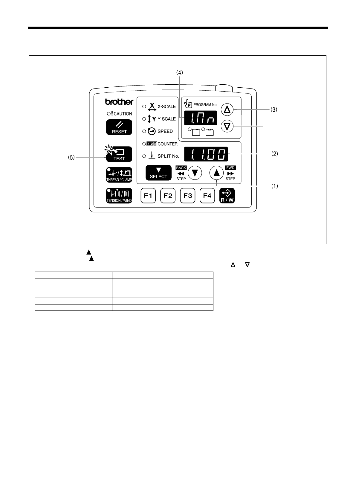
2-10. Software version checking method
TEST indicator illuminates, Menu indicator switches off
1. While pressing the
* Keep pressing the key (1) until the model name is displayed and the buzzer beeps once.
2. The display in the PROGRAM No. display (4) switches as follows each time the or key (3) is pressed.
PROGRAM No. display (4) Software
[1.Mn] Main CPU
[2.Mt] Motor CPU
[3.PL] Panel CPU
[4.iP] Main CPU (IPL)
[5.PG] Programmer
3. When the TEST key (5) is pressed, the display will return to the normal display and the sewing machine will change to
home position standby.
key (1), turn on the power. The software version will be displayed in the menu display (2).
5059Q
22
BAS-311G, BAS-326G
Page 30
3. READING / WRITING DATA
3. READING / WRITING DATA
3-1. Handling data
Program numbers (100 − 999) are read from CF cards.
Program numbers (0 − 99) are older BAS-300 series, BAS-300A series and BAS-300E/F series data and can be read from
floppy disks.
However, when memory switch No. 755 is set to ON, data for older series models (program numbers 0 − 99) can be
transferred from a floppy disk to a CF card using a computer and then be read from the CF card.
* In such cases, the effective reading mode will be [r 1].
Option
0 − 99
or
r9 mode
0 − 99
Old model series data range
(BAS***.SEW)
100 − 999
or
r1 mode
100 − 999
BAS-311G, BAS-326G data range
ISM***.SEW
Sewing machine internal memory
Old model series data copied from floppy
r1 mode
disk to CF card
(0 − 99)
When memory switch
No. 755 = ON
100 − 999
or
r1 mode
BAS-311G, BAS-326G
23
Page 31

3. READING / WRITING DATA
3-2. Notes on handling CF cards (sold separately)
• Use a CF card with a memory capacity of 32, 64, 128 or 256 MB.
• Do not disassemble or modify the CF card.
• Do not bend, drop or scratch CF cards or place heavy objects on top of them.
• Avoid contact with liquids such as water, oil, solvents or drinks.
• Use and store CF cards in locations that are free from strong static electricity and electrical interference.
• Do not use or store CF cards in places where they may be subject to vibrations or shocks, direct sunlight, high
temperature or humidity or strong magnetic fields from equipment such as speakers, or places which are dusty from thread
scraps, etc.
• Do not subject CF cards to shocks or impacts or remove them from the sewing machine while data is being loaded or
written.
• The data on the CF cards may become lost or corrupted due to some malfunction or accident. It is recommended that you
make a backup of important data.
• CF cards should only be removed after the power for the sewing machine has been turned off.
• CF cards are already formatted when they are purchased, and so you should not reformat them.
• The recommended CF cards are commercially-available ones from SanDisk or HAGIWARA SYS-COM. CF cards from
other manufacturers can be used, but different formatting methods may mean that loading from or writing to such cards
may not be possible.
For more information, refer to the documentation provided with the CF card.
* This product is compatible with CF cards that have been formatted using the FAT16 method. Cards that have been
formatted using the FAT32 method cannot be used.
TM
* CF
* Company names and product names appearing in this manual are trademarks or registered trademarks of the
is a trademark of SanDisk Corporation.
respective owners. However, no TM or other similar symbols appear in the main text of this manual.
3-3. Structure of a CF card folder
\BROTHER\ISM\ISMSYS\ISM02MN.MOT : Control program
\BROTHER\ISM\ISMDB00\ISMMSW.SEW : Memory switch data
*1 \ISMUPG.SEW : User program data
\ISMHST.SEW : Error log data
\ISMS0100.SEW : Sewing data P No. = 100
\ISMS0101.SEW : Sewing data P No. = 101
\ISMS0102.SEW : Sewing data P No. = 102
*1 The underlined portion of the name of the \BROTHER\ISM\SMDB00 folder for sewing data can be changed by
changing the setting for memory switch No. 752 in order to change the folder name. Change the folder name if you
would like to store sewing data for different sewing machines on a single CF card.
24
BAS-311G, BAS-326G
Page 32
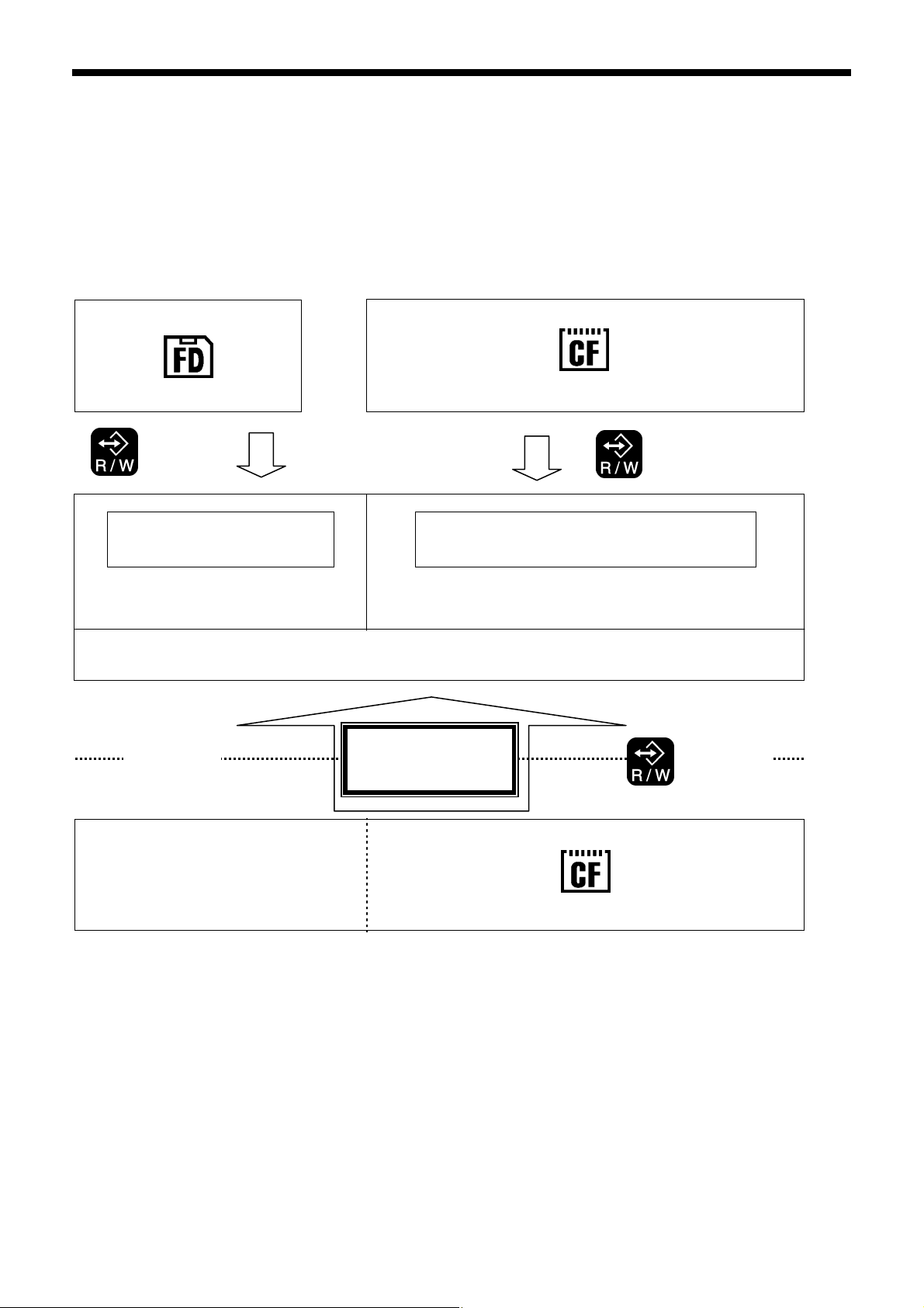
3-4. Data read/write mode
1
Turn on the power switch.
2
Switch to data read/write mode.
3
TEST indicator and CF media indicator illuminate
4
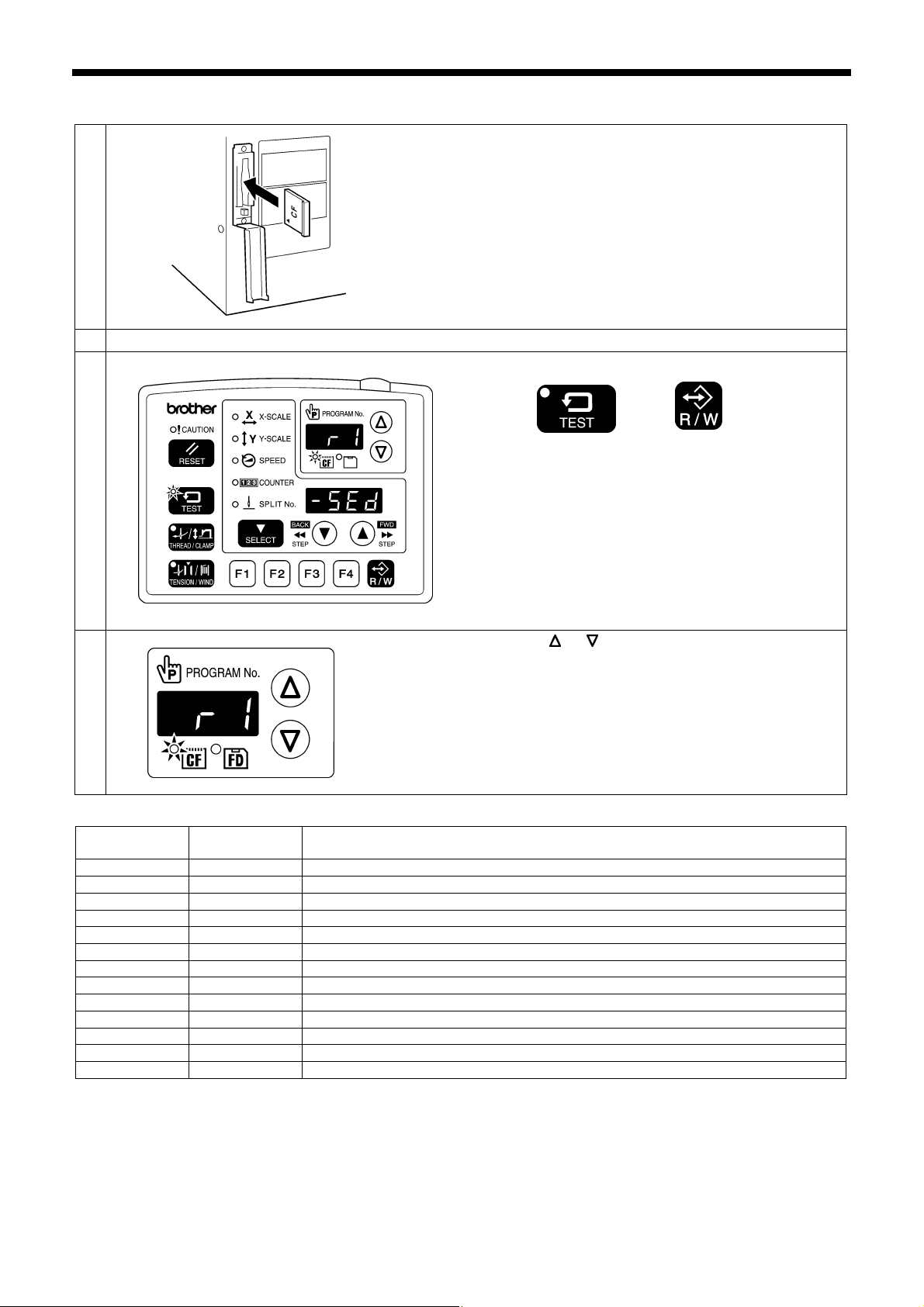
3. READING / WRITING DATA
With the power turned off, insert the CF card into the CF
slot.
NOTE:
• Make sure the CF card is facing the correct way.
• Always be sure to keep the cover closed except
when inserting and removing the CF card. If this is
not done, dust may get inside and cause problems
with operation.
• If no valid data can be found, the CF media indicator
will not illuminate.
4453Q
While pressing the TEST key, press the R/W key.
• The mode number will appear in the PROGRAM No.
display, and the setting details for that mode will
appear in the menu display.
• The initial mode is sewing data reading mode. (Refer
to the read/write mode list)
4574Q
Press the or key to select the mode.
4575Q
[Read/write mode list]
PROGRAM No.
display
r 1 [-SEd] Sewing data is read from the CF card. (*1)
w 2 [SEd-] Sewing data is written to the CF card.
r 3 [-MEM] Memory switch settings are read from the CF card.
w 4 [MEM-] Memory switch settings are written to the CF card.
r 5 [-UPG] User programs are read from the CF card.
w 6 [UPG-] User programs are written to the CF card.
r 7 [-SyS] Control programs are read from the CF card and used to update the firmware version.
w 8 [LoG-] Error log data is written to the CF card.
r 9 [-Fdd] Sewing data is read from the floppy disk. (*2) (*3)
w 10 [Fdd-] Sewing data is written to the floppy disk. (*2)
r 11 [-EoP] Extended option output (*4) data is read from the CF card.
w 12 [EoP-] Extended option output data is written to the CF card.
r 13 [oPFd] Extended option output data is read from the floppy disk. (*2)
*1 The sewing data that can be use with this sewing machine is data that has been created for the BAS-311G/BAS-326G.
*2 Only valid when using an optional floppy disk drive.
*3 Sewing data for the BAS-300 series, BAS-300A series and BAS-300E/F series can be read.
*4 Refer to the instruction manual for the programmer for details on extended option output.
Menu display Setting items
BAS-311G, BAS-326G
25
Page 33
3. READING / WRITING DATA
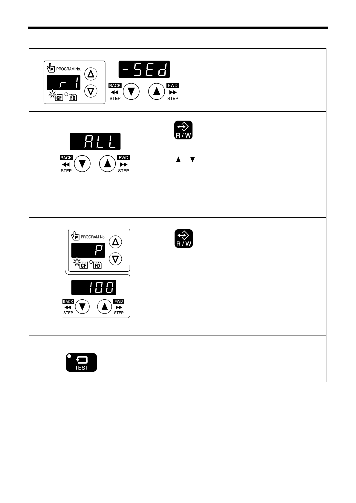
3-5. Reading sewing data from CF cards
1
2
3
End data read/write mode
4
TEST indicator switches off
Loading
Press the R/W key.
• [-SEd] will change to [ ALL].
Press the
read.
* If [ ALL] is selected, all sewing data (Nos. 100—999) will be read at
once.
[When memory switch No. 755 is ON]
The program number (0 − 99) is also displayed and can be selected.
If you select [ ALL] at this time, all sewing data (Nos. 0 − 999) will be
read at once.
Press the R/W key.
• The buzzer will sound and the selected sewing data will be loaded
from the CF card and copied into the sewing machine's internal
memory.
• The program numbers that have been read will be displayed in the
menu display.
* If there is a large volume of data in the CF card, it will take some time
for all of it to be read. To halt the reading of data, press the STOP
switch. If you then press the RESET key, the display will change back
to [ ALL].
Press the TEST key.
Turn off the power switch, remove the CF card, and then close the cover
of the CF slot.
or key to select the program number (100 − 999) to be
Select the [r 1] data read/write mode.
4576Q
4577Q
4976Q
26
BAS-311G, BAS-326G
Page 34
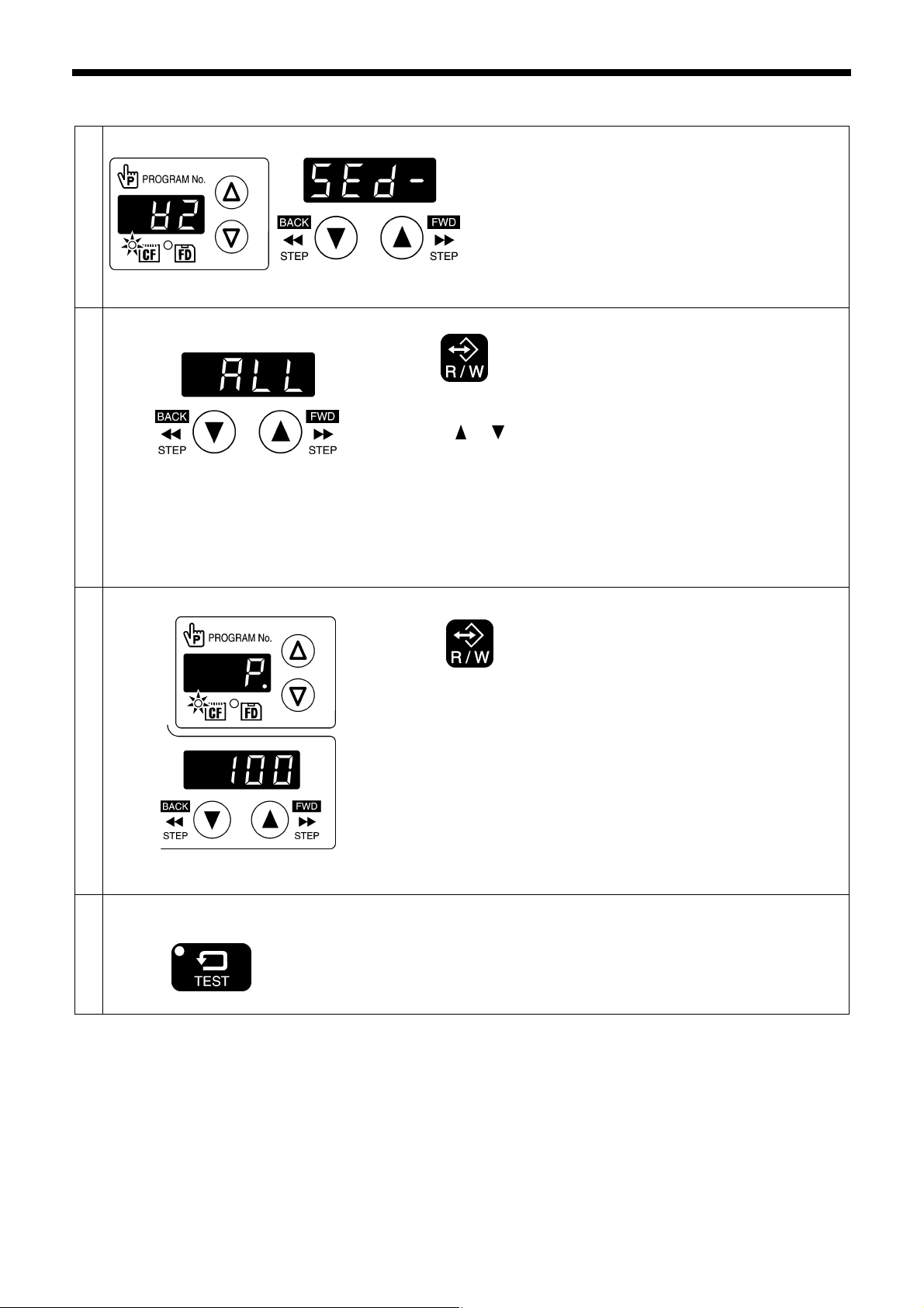
3-6. Writing sewing data to CF cards
1
2
Press the R/W key.
• [SEd-] will change to [ ALL].
Press the
written.
* If you select [ ALL], all sewing data (Nos. 100 − 999) will be written at
once.
3. READING / WRITING DATA
Select the [w 2] data read/write mode.
4578Q
or key to select the program numbers (100 − 999) to be
3
End data read/write mode
4
Writing
TEST indicator switches off
[When memory switch No. 755 is ON]
The program numbers (0 − 99) will also be displayed and can be
selected. If you select [ ALL] at this time, all sewing data (Nos. 0 − 999)
will be written at once.
Press the R/W key.
• The buzzer will sound and the selected sewing data will be copied from
the internal memory onto the CF card.
• The program numbers that have been written will appear in the
PROGRAM No. display.
* If there is a large volume of data in the internal memory, it will take
some time for all of it to be written. To halt the writing of data, press the
STOP switch. If you then press the RESET key, the display will change
back to [ ALL].
Press the TEST key.
Turn off the power switch, remove the CF card, and then close the cover
of the CF slot.
4577Q
4977Q
BAS-311G, BAS-326G
27
Page 35
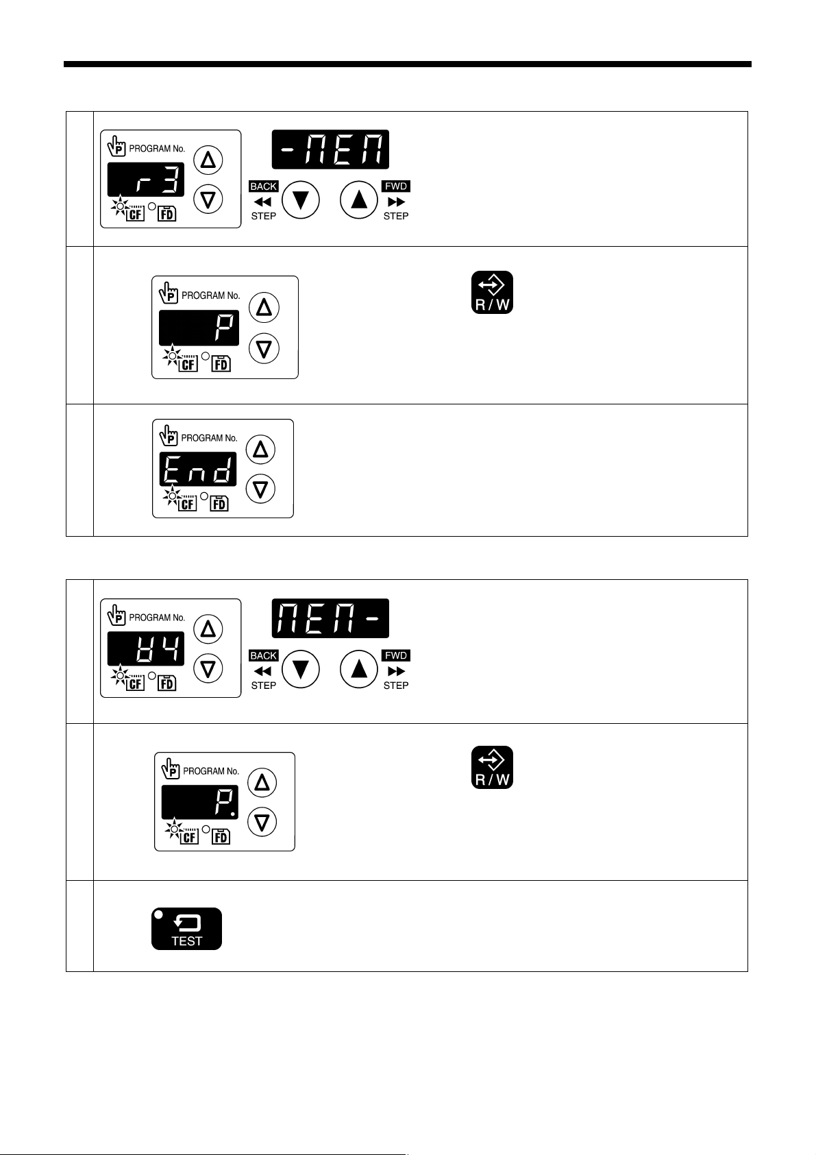
3. READING / WRITING DATA
3-7. Reading memory switch data from CF cards
1
2
3
Loading
Select the [r 3] data read/write mode.
Press the R/W key.
• The buzzer will sound and the memory switch data will
be loaded from the CF card and copied into the sewing
machine's internal memory.
When [ End] is displayed, the process is complete.
Turn off the power switch, remove the CF card, and then
close the cover of the CF slot.
4580Q
4498Q
3-8. Writing memory switch data to CF cards
1
2
End data read/write mode
3
Writing
TEST indicator switches off
Select the [w 4] data read/write mode.
Press the R/W key.
• The buzzer will sound and the memory switch data will
be copied from the internal memory onto the CF card.
Press the TEST key.
Turn off the power switch, remove the CF card, and then
close the cover of the CF slot.
4581Q
4582Q
4579Q
28
BAS-311G, BAS-326G
Page 36
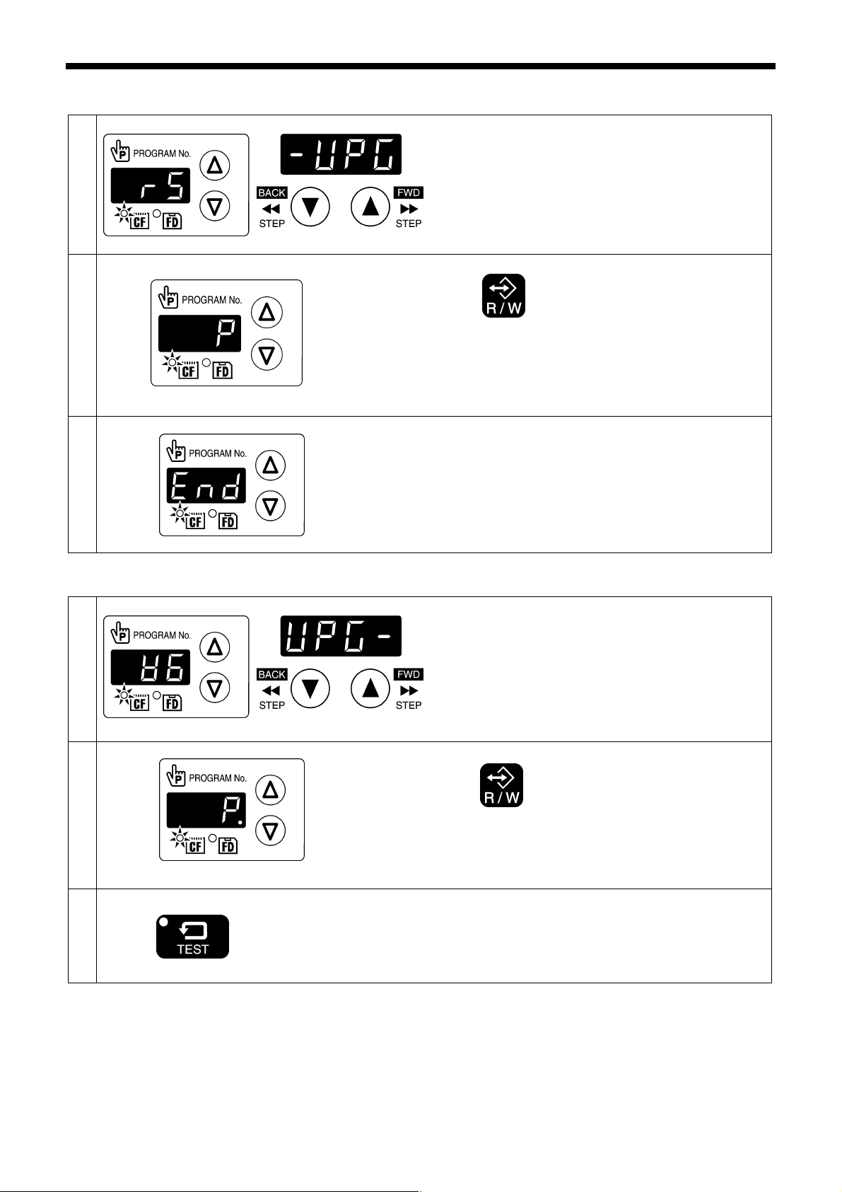
3-9. Reading user program data from CF cards
1
2
Loading
3
Select the [r 5] data read/write mode.
Press the R/W key.
• The buzzer will sound and the user program data will
be loaded from the CF card and copied into the sewing
machine's internal memory.
When [ End] is displayed, the process is complete.
Turn off the power switch, remove the CF card, and then
close the cover of the CF slot.
3-10. Writing user program data to CF cards
1
2
End data read/write mode
3
Writing
TEST indicator switches off
Select the [w 6] data read/write mode.
Press the R/W key.
• The buzzer will sound and the user program data will
be copied from the internal memory onto the CF card.
Press the TEST key.
Turn off the power switch, remove the CF card, and then
close the cover of the CF slot.
3. READING / WRITING DATA
4583Q
4498Q
4581Q
4584Q
4579Q
BAS-311G, BAS-326G
29
Page 37
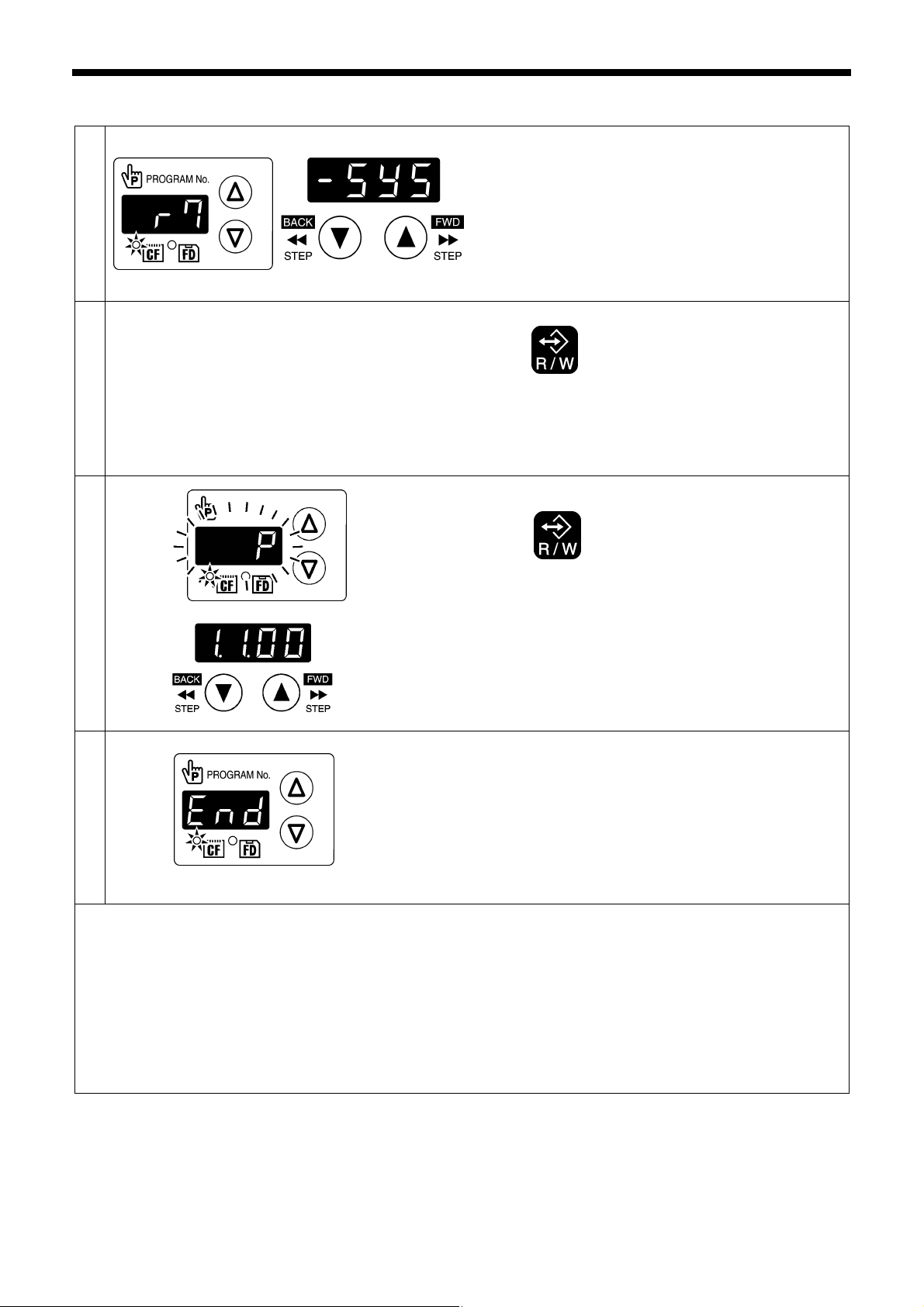
3. READING / WRITING DATA
3-11. Updating the control program
1
2
Select the [r 7] data read/write mode.
4585Q
Press the R/W key.
• [-SyS] will be displayed for a certain amount of time, and
then the display will change to [ vEr], and after that the
version number of the control program that is stored on
the CF card will be displayed.
3
4
<Restoring the control program if an error occurs during updating>
5060Q
4581Q
Press the R/W key.
• [ P] will flash in the PROGRAM No. display and the
control program will be updated.
NOTE:
If the filename and folder name for the control program
are incorrect, error [E421] will be displayed.
When [ End] is displayed, the process is complete.
Turn off the power switch, remove the CF card, and then
close the cover of the CF slot.
NOTE:
• Version updating may take about 3 − 10 minutes.
(The time taken will vary depending on the
manufacturer and storage capacity of the CF card
being used. )
• Never remove the CF card or turn off the power
switch while reading of the CF card is in progress.
If the version updating did not complete normally, such as because of a power outage, the sewing machine will not operate
correctly.
If this happens, restore the control program by the following procedure.
1. Insert the CF card containing the control program data into the CF card slot.
2. Turn on the power switch. The operation panel will switch off and the version updating will be carried out.
3. When the initial screen turns back on, the updating is complete. Turn off the power switch, remove the CF card, and
then close the cover of the CF slot.
30
BAS-311G, BAS-326G
Page 38

3-12. Writing error log data to CF card
1
2
End data read/write mode
3
Writing
TEST indicator switches off
Select the [w 8] data read/write mode.
Press the R/W key.
• The buzzer will sound and the error log data will be
copied from the internal memory onto the CF card.
Press the TEST key.
Turn off the power switch, remove the CF card, and then
close the cover of the CF slot.
3-13. Reading sewing data from floppy disks
3. READING / WRITING DATA
5061Q
4579Q
Insert the floppy disk into the floppy disk drive.
1
2
3
Select the [r 9] data read/write mode.
5062Q
Press the R/W key.
• [-Fdd] will change to [ ALL].
Press the
* Program numbers that contain no data will also be displayed at this
time.
* If [ ALL] is selected, all sewing data will be read at once.
or key to select the program number to be read.
4577Q
BAS-311G, BAS-326G
31
Page 39

3. READING / WRITING DATA
4
End data read/write mode
5
Loading
TEST indicator switches off
Press the R/W key.
• The buzzer will sound and the selected sewing data will be loaded
from the floppy disk and copied into the sewing machine's internal
memory.
• The program numbers that have been read will appear in the menu
display.
* If there is a large volume of data in the floppy disk, it will take some
time for all of it to be read.
To halt the reading of data, press the STOP switch. If you then
press the RESET key, the display will change back to [ ALL].
NOTE:
If there is no data in the selected program number, error [E421] will
be displayed. Press the RESET key and then select another
program number.
Press the TEST key.
Turn off the power and remove the floppy disk.
3-14. Writing sewing data to floppy disks
5063Q
Insert the floppy disk into the floppy disk drive.
1
2
3
Select the [w 10] data read/write mode.
5064Q
Press the R/W key.
• [Fdd-] will change to [ ALL].
Press the
be written.
* If [ ALL] is selected, all sewing data will be written at
once.
or key to select the program number to
4577Q
32
BAS-311G, BAS-326G
Page 40
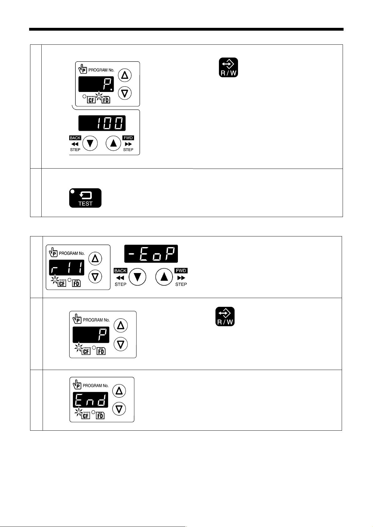
3. READING / WRITING DATA
4
End data read/write mode
5
Writing
TEST indicator switches off
Press the R/W key.
• The buzzer will sound and the selected sewing data
will be copied from the internal memory onto the floppy
disk.
• The program numbers that have been written will
appear in the menu display.
* If there is a large volume of data in the internal
memory, it will take some time for all of it to be written.
To halt the writing of data, press the STOP switch. If
you then press the RESET key, the display will change
back to [ ALL].
Press the TEST key.
Turn off the power and remove the floppy disk.
3-15. Reading extended option output data from a CF card
1
2
3
Loading
Select the [r 11] data read/write mode.
Press the R/W key.
• The buzzer will sound and the extended option output
data will be loaded from the CF card and copied into
the sewing machine's internal memory.
When [ End] is displayed, the process is complete.
Turn off the power switch, remove the CF card, and then
close the cover of the CF slot.
5065Q
5066Q
4498Q
4581Q
BAS-311G, BAS-326G
33
Page 41

3. READING / WRITING DATA
3-16. Writing extended option output data to CF cards
1
2
End data read/write mode
3
Writing
TEST indicator switches off
Select the [w 12] data read/write mode.
Press the R/W key.
• The buzzer will sound and the extended option output
data will be copied from the internal memory onto the
CF card.
Press the TEST key.
Turn off the power switch, remove the CF card, and then
close the cover of the CF slot.
3-17. Reading extended option output data from floppy disks
5067Q
4579Q
Insert the floppy disk into the floppy disk drive.
1
2
3
4
Loading
Select the [r 13] data read/write mode.
5068Q
Press the R/W key.
• The buzzer will sound and the extended option output
data will be loaded from the floppy disk and copied into
the sewing machine's internal memory.
5069Q
When [ End] is displayed, the process is complete.
Turn off the power and remove the floppy disk.
34
5070Q
BAS-311G, BAS-326G
Page 42

4. MECHANICAL DESCRIPTIONS
The mechanisms operate in the order of the numbers given in the illustrations.
4-1. Needle bar and thread take-up mechanisms
4. MECHANICAL DESCRIPTIONS
5041Q
1. Motor assy
2. Upper shaft
3. Thread take-up crank
4. Needle bar crank
5. Needle bar connecting rod
<5> Thread take-up lever assy
6. Needle bar clamp
<6> Thread take-up support
7. Needle bar
4-2. Lower shaft and shuttle race mechanisms
5042Q
1. Motor assy
2. Upper shaft
3. Crank rod assy
4. Rock gear
5. Lower gear
6. Lower shaft
7. Driver
8. Shuttle hook
BAS-311G, BAS-326G
35
Page 43

4. MECHANICAL DESCRIPTIONS
r
4-3. Work clamp lifter mechanism (Solenoid specifications)
1. Work clamp pulse moto
2. Work clamp driving gear
3. Work clamp cam gear
4. Work clamp cam
5. Work clamp driving lever
6. Work clamp lifter link
7. Work clamp lifter lever
8. Work clamp lifter plate assy
5044Q
5043Q
9. Slider
10. Work clamp lifter lever
11. Connecting rod
12. Connecting link
13. Work clamp lifter lever
14. Work clamp
36
BAS-311G, BAS-326G
Page 44

4. MECHANICAL DESCRIPTIONS
r
r
4-4. Work clamp lifter mechanism (Pneumatic specifications)
1. Air cylinde
2. Work clamp lifter lever
3. Work clamp lifter lever
4. Work clamp
5045Q
4-5. Intermittent presser foot lifter mechanism
5046Q
1. Work clamp pulse moto
2. Work clamp driving gear
3. Work clamp cam gear
4. Stepping foot driving lever
5. Stepping clamp lifter rod
6. Stepping clamp lifter
7. Stepping clamp lifter link
8. Stepping clamp link
9. Stepping clamp link B
10. Presser bar clamp
11. Presser bar
12. Presser foot
BAS-311G, BAS-326G
37
Page 45

4. MECHANICAL DESCRIPTIONS
4-6. Intermittent presser foot stroke mechanism
5047Q
1. Motor assy
2. Upper shaft
3. Stepping clamp cam
4. Stepping clamp connecting rod
5. Stepping clamp arm R
6. Stepping clamp arm F
7. Stepping clamp link A
8. Stepping clamp link A
9. Stepping clamp link B
10. Presser bar clamp
11. Presser bar
12. Presser foot
38
BAS-311G, BAS-326G
Page 46

4-7. Feed mechanism
Sewing patterns are created through combinations of X and Y movements.
X direction
Y direction
4. MECHANICAL DESCRIPTIONS
5052Q
1. X-feed motor assy
2. Gear
3. X-feed gear
4. Y-ball spline
5. X-GT belt
6. Feed bracket X
5053Q
1. Y-feed motor L assy
2. Gear
3. Y-feed gear
4. Y-GT belt
5. Feed bracket assy
BAS-311G, BAS-326G
39
Page 47

4. MECHANICAL DESCRIPTIONS
4-8. Thread trimmer mechanism
5048Q
1. Thread trimmer solenoid
2. Solenoid lever
3. Pushing lever
4. Driving lever
5. Thread trimmer collar
6. Thread trimmer cam
7. Thread trimmer rod V
8. Thread trimmer lever V
9. Thread trimmer lever H
10. Thread trimmer rod H
11. Movable knife lever
12. Movable knife connecting plate
13. Movable knife
14. Fixed knife
40
BAS-311G, BAS-326G
Page 48

4-9. Tension release mechanism
5049Q
4. MECHANICAL DESCRIPTIONS
1. Tension release solenoid
2. Bolt
3. Tension release bar
4. Tension release pin
4-10. Thread wiper mechanism
5050Q
1. Thread wiper solenoid assy
2. Thread wiper rod
3. Thread wiper crank assy
4. Wiper
When the thread wiper solenoid assembly is turned off,
the wiper operates in the opposite direction.
BAS-311G, BAS-326G
41
Page 49
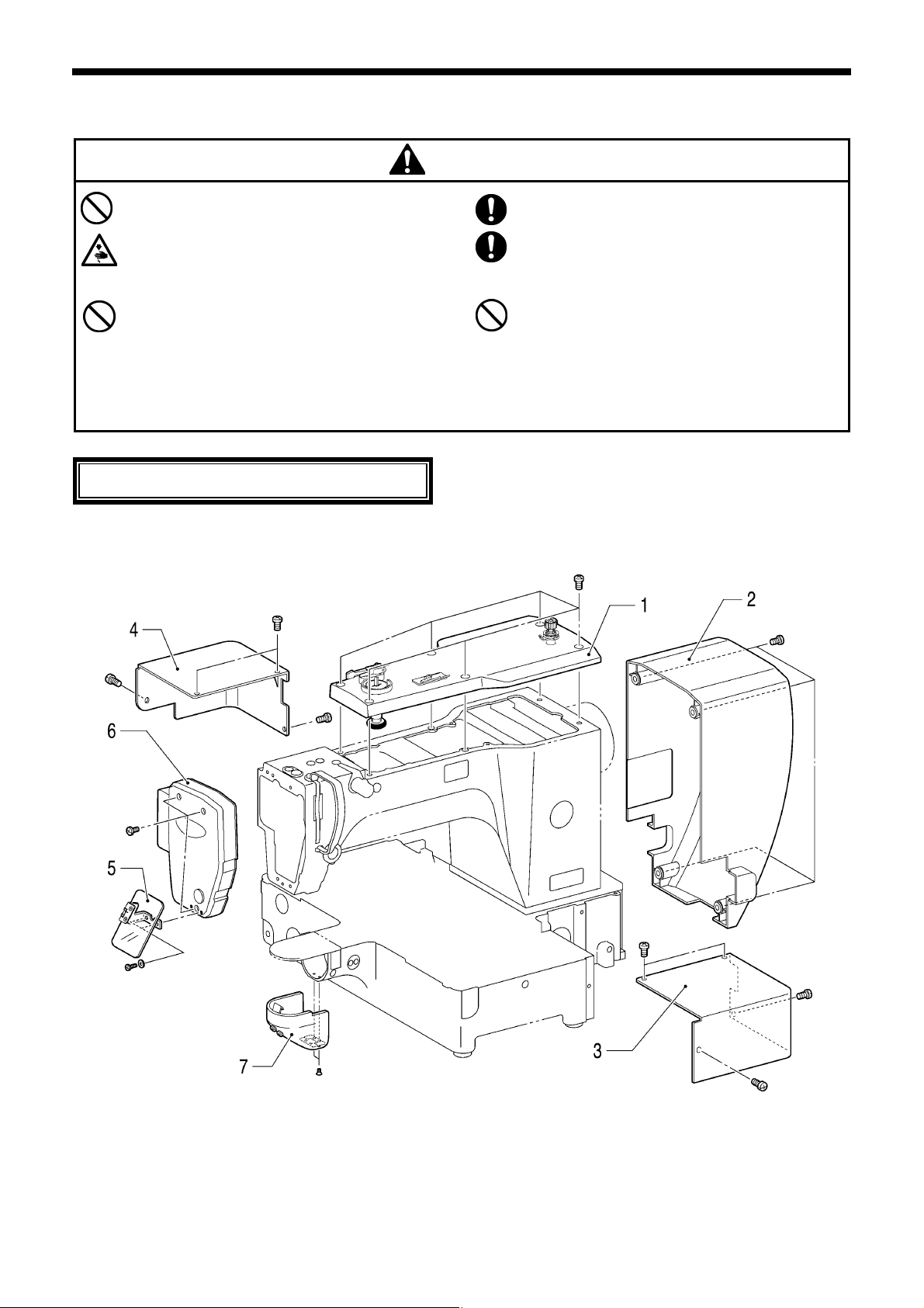
5. DISASSEMBLY
r
5. DISASSEMBLY
Disassembly should only be carried out by a
qualified technician.
Turn off the power switch before carrying out
disassembly. If the foot switch is depressed by
mistake, the sewing machine might start operating
and injury could result.
Be sure to wear protective goggles and gloves when
handling the lubricating oil and grease, so that they
do not get into your eyes or onto your skin. If the oil
and grease get into your eyes or onto your skin,
inflammation can result.
Furthermore, do not drink or eat the lubricating oil or
grease. They may cause diarrhea or vomiting.
Keep the oil out of the reach of children.
Disassemble each part in order of the numbers.
CAUTION
Use only the proper replacement parts as specified
by Brother.
If any safety devices have been removed, be
absolutely sure to re-install them to their original
positions and check that they operate correctly
before using the machine.
Any problems in machine operation which result
from unauthorized modifications to the machine will
not be covered by the warranty.
5-1. Covers
1. Top cove
2. Motor cover
3. Motor cover R
4. Motor cover L
5. Eye guard
6. Face plate
7. Shuttle race cover assy
5051Q
42
BAS-311G, BAS-326G
Page 50
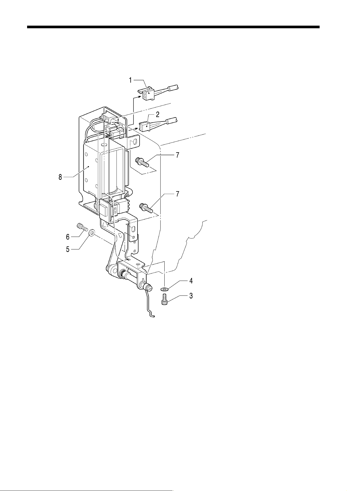
5-2. Thread wiper mechanism
5. DISASSEMBLY
5090Q
1. Thread wiper solenoid harness (Pull out)
2. STOP switch harness (Pull out)
3. Bolt
4. Plain washer
5. Removed washer (Assemble)
6. Removed bolt (Assemble)
7. Bolts with washer [2 pcs]
8. Thread wiper unit
BAS-311G, BAS-326G
43
Page 51
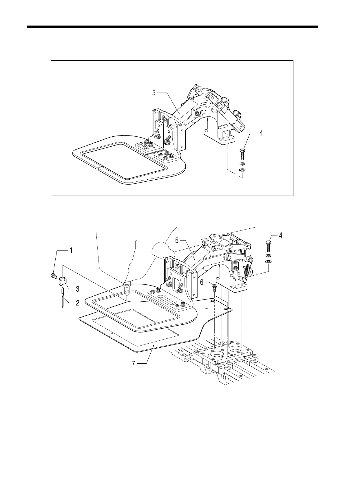
5. DISASSEMBLY
5-3. Work clamp arm mechanism
Pneumatic specifications
5054Q
5055Q
1. Set screw
2. Needle
3. Needle bar thread guide
4. Bolts [4 pcs]
5. Work clamp assy
6. Bolts with washer [2pcs]
7. Feed plate
44
BAS-311G, BAS-326G
Page 52
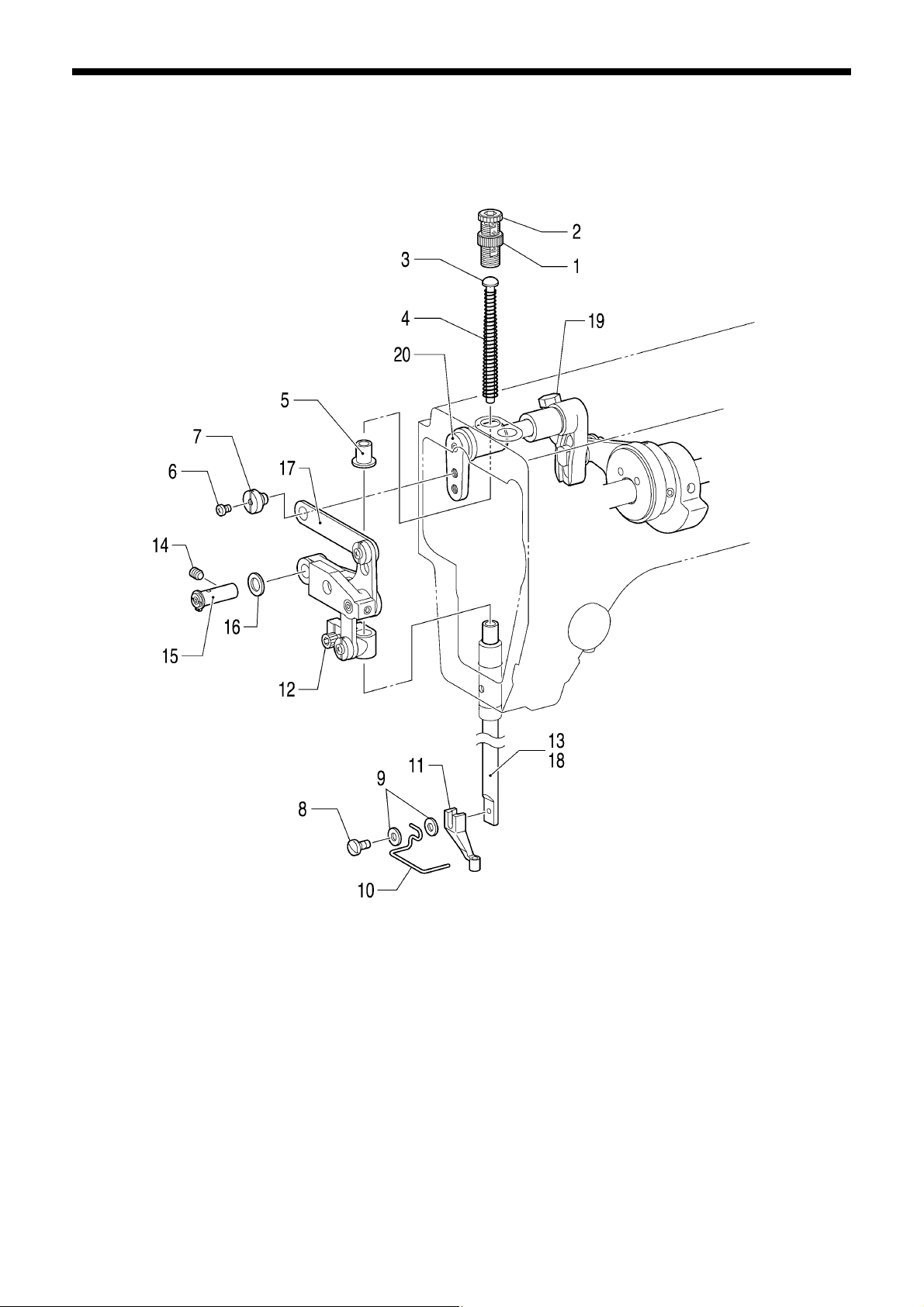
5-4. Intermittent presser foot lifter mechanism (1)
1. Adjusting screw nut (Loosen)
2. Presser adjusting screw
3. Presser bar spring guide
4. Presser bar spring
5. Presser bar spring collar
6. Screw
7. Shoulder screw
8. Screw
9. Plain washers [2 pcs]
10. Finger guard
11. Presser foot
12. Bolt (Loosen)
13. Presser bar (Pull downward from presser bar clamp)
14. Set screw (Loosen)
15. Link shaft (Pull out)
16. Washer
17. Stepping clamp lifter link (Remove as unit)
18. Presser bar
19. Bolt (Loosen)
20. Stepping clamp arm F
5. DISASSEMBLY
5091Q
BAS-311G, BAS-326G
45
Page 53

5. DISASSEMBLY
f
5-5. Needle bar mechanism
Left-hand thread
1. Rubber cap
2. Screw
3. Needle bar
4. Needle bar clamp (Pull out)
5. Slide block
6. Rubber caps [2 pcs]
7. Set screws [2 pcs] (Loosen)
8. Thread take-up support shaft assy
9. Thread take-up support
10. Screw (Loosen)
5092Q
5093Q
Do not remove the slide block guide i
possible to prevent the machine from
overheating due to needle bar rubbing.
11. Needle bar connecting rod
12. Needle bearing
13. Rubber cap
14. Set screws [3 pcs] (Loosen)
15. Needle bar crank
16. Needle bearing
17. Thread take-up lever assy
18. Washer
19. Bolts [2 pcs]
20. Slide block guide
46
BAS-311G, BAS-326G
Page 54
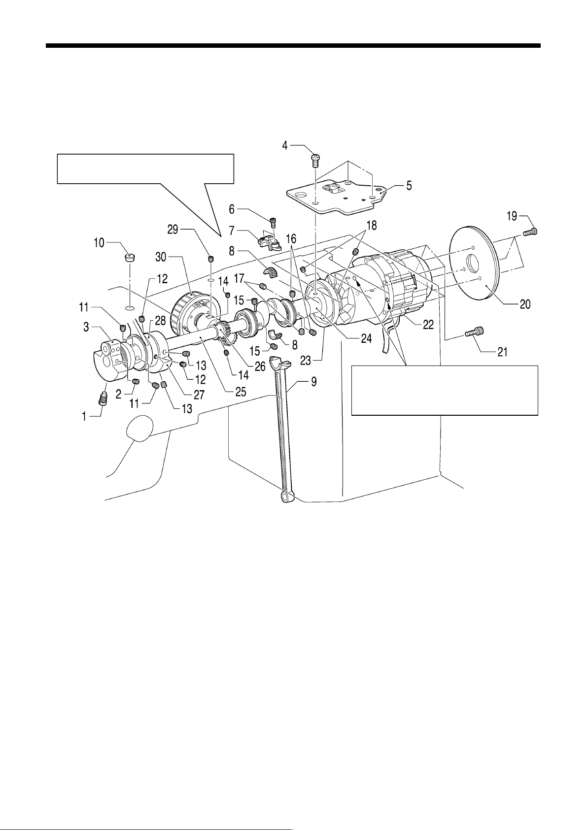
5-6. Upper shaft mechanism
Be careful not to drop the needle
bearing.
1. Screw (Loosen)
2. Set screw (Loosen)
3. Thread take-up crank
4. Screws [3 pcs] (Loosen)
5. Crank cover
6. Bolts [2 pcs]
7. Crank rod [Upper part]
8. Needle bearing
9. Crank rod [Lower part] (Lower downward)
10. Rubber cap
11. Set screws [2 pcs] (Loosen)
12. Set screws [2 pcs] (Loosen)
13. Set screws [2 pcs] (Loosen)
14. Set screws [2 pcs] (Loosen)
15. Set screws [2 pcs] (Loosen)
5. DISASSEMBLY
If the motor assembly cannot be removed,
insert bolts into these two tapping holes
and gradually tighten them to remove the
motor assembly.
5094Q
16. Set screws [2 pcs] (Loosen)
17. Set screws [2 pcs] (Loosen)
18. Set screws [2 pcs] (Loosen)
19. Screws [3 pcs] (Loosen)
20. Fries wheels [2 pcs]
21. Bolts [4 pcs] (Loosen)
22. Motor assy
23. Thread trimmer cam
24. Joint assy
25. Upper shaft
26. Pulley gear R
27. Bobbin winder driving wheel
28. Stepping clamp cam assy
29. Set screw (Loosen)
30. Pulley assy
BAS-311G, BAS-326G
47
Page 55

5. DISASSEMBLY
5-7. Lower shaft mechanism
5095Q 5096Q
Remove the rock gear and the
crank rod together as a single unit.
5098Q
If the adjusting stud will not pull out,
insert a M3 screw into the tap hole and
then pull out the adjusting stud.
1. Bolt (Loosen)
2. Driver
3. Retaining ring E
4. Set screw (Loosen)
5. Adjusting stud (Pull out)
6. Lower shaft assy
[Pull out from the rear of the machine]
7. Adjusting stud (Pull out)
8. Set screw (Loosen)
9. Screw (Loosen)
10. Shuttle race base assy
5097Q
11. Set screws [2 pcs] (Loosen)
12. Set screw (Loosen)
13. Set screw collar, R
14. Set screws [2 pcs] (Loosen)
15. Set screw collar, B
16. Rock gear shaft
[Pull out from the rear of the machine]
17. Rock gear
18. Crank rod [Lower part]
48
BAS-311G, BAS-326G
Page 56
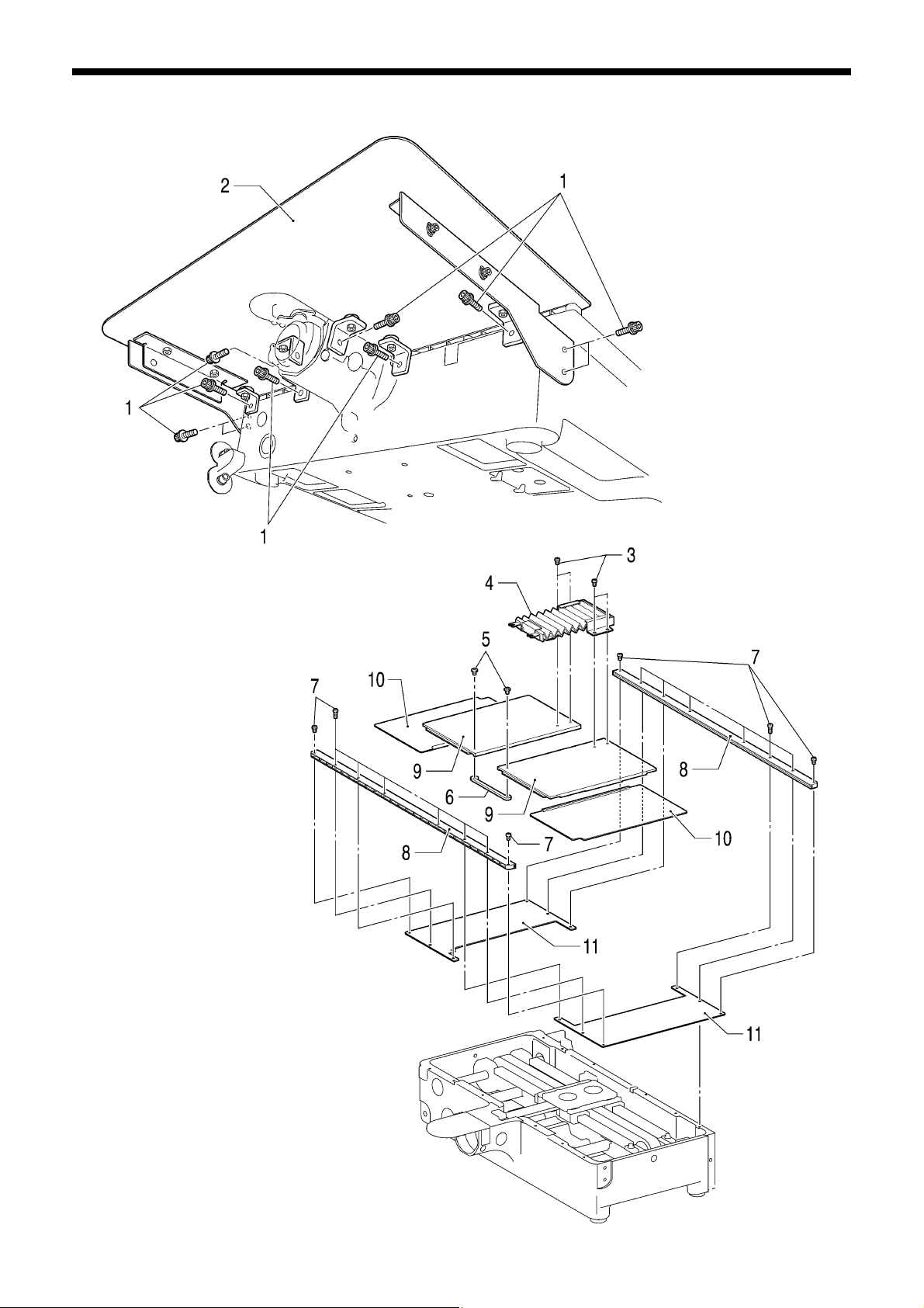
5-8. Feed covers
1. Bolts with washer [10 pcs]
2. Auxiliary plate
3. Screws [4 pcs]
4. Bellow assy
5. Screws [2 pcs]
6. Cover connecting plate
7. Screws [16 pcs]
8. Cover rails [2 pcs]
9. Inside covers [2 pcs]
10. Outside covers [2 pcs]
11. Fixed covers [2 pcs]
5. DISASSEMBLY
5101Q
5102Q
BAS-311G, BAS-326G
49
Page 57

5. DISASSEMBLY
5-9. Feed mechanism
5104Q
50
5103Q
BAS-311G, BAS-326G
1. Bolts with washer [2 pcs] (Loosen)
2. Screws [5 pcs], flat screws [3 pcs]
3. Oil cover
4. Screws with washer [4 pcs]
5. Y belt cover
6. Bolts with washer [3 pcs]
7. Y-feed motor L assy
8. Set screws [2 pcs] (Loosen)
9. Y-feed gear
10. Retaining ring E
11. Set screws [2 pcs] (Loosen)
12. Y-pulley driving shaft
13. Y-pulley assy
14. Y-pulley collar
15. Ball bearings [2 pcs]
16. Bolts [4 pcs]
17. Bolts [4 pcs]
18. Y-belt presser plate
19. Y-belt support plate
20. Set screws [2 pcs] (Loosen)
21. Y-pulley bracket
22. Y-pulley fulcrum shaft
23. Y-pulley assy
24. Y-GT belt
25. Ball bearings [2 pcs]
5105Q
Page 58

5. DISASSEMBLY
5117Q
26. Bolts with washer [3 pcs]
27. X-feed motor assy
28. Set screws [2 pcs] (Loosen)
29. X-feed gear
30. Rubber cap
31. Y-ball spline
32. Retaining ring C
33. Plain washer
34. Ball bearing
35. Ball bearings [2 pcs]
36. Bolts [4 pcs]
37. Washers [4 pcs]
38. Bolts [8 pcs]
39. Spring washers [8 pcs]
40. Plain washers [8 pcs]
41. Y-LM guides [2 pcs]
42. Flat screws [16 pcs]
43. Y-LM spacers [2 pcs]
5106Q
5107Q
BAS-311G, BAS-326G
51
Page 59

5. DISASSEMBLY
44. Bolts [10 pcs]
45. Flat screws [8 pcs]
46. Feed bracket X
47. Bolts [16 pcs]
48. X-LM guide [2 pcs]
49. Bolts [2 pcs]
50. X-belt holder
51. X-belt holder plate
52. Bolts [2 pcs]
53. Plain washers [2 pcs]
54. Set screws [2 pcs] (Loosen)
55. X-pulley fulcrum shaft
56. X-pulley bracket
57. X-right pulley assy
58. Plain washer
59. X-GT belt
5118Q
52
BAS-311G, BAS-326G
Page 60

r
5-10. Work clamp lifter mechanism (Solenoid specifications)
1. Shoulder screw
2. Work clamp spring
3. Rubber cap
4. Link shoulder screws [2 pcs]
5. Work clamp lifter link (Pull backward)
6. Bolts [4 pcs]
7. Work clamp pulse motor
(Disconnect the harness)
8. Set screws [2 pcs] (Loosen)
9. Work clamp driving gear
10. Bolts [2 pcs]
11. Work clamp motor plate
12. Set screw (Loosen)
13. Work clamp lever shaft
14. Work clamp driving leve
15. Washer
16. Stepping foot driving lever
17. Set screws [2 pcs] (Loosen)
18. Set screws [2 pcs] (Loosen)
19. Screw
20. Plain washer
21. Retaining ring C
22. Work clamp fulcrum shaft
23. Work clamp cam gear
24. Work clamp cam
25. Ball bearings [2 pcs]
5. DISASSEMBLY
5108Q
BAS-311G, BAS-326G
53
Page 61

5. DISASSEMBLY
26. Set screws [2 pcs] (Loosen)
27. Retaining ring E
28. Work clamp lever shaft B
29. Plain washer
30. Work clamp lifter lever
31. Slide block
32. Work clamp lifter plate assy
33. Bolts [4 pcs]
34. Slide bush
Note:
Hold the work clamp lifter plate assembly when
removing work clamp lifter lever, otherwise the
work clamp lifter plate assembly may fall down.
5109Q
5-11. Work clamp lifter mechanism (Pneumatic specifications)
1. Shoulder screw
2. Bolts [4 pcs]
3. Work clamp pulse motor (Disconnect the harness)
4. Set screws [2 pcs] (Loosen)
5. Work clamp driving gear
6. Bolts [2 pcs]
7. Work clamp motor plate
8. Set screws [2 pcs] (Loosen)
9. Set screw
10. Work clamp lever shaft
11. Set screw collar
12. Stepping foot driving lever
13. Set screw (Loosen)
14. Set screw (Loosen)
15. Screw
16. Plain washer
17. Retaining ring C
18. Work clamp fulcrum shaft
19. Work clamp cam gear
20. Ball bearings [2 pcs]
5110Q
54
BAS-311G, BAS-326G
Page 62

5-12. Tension release mechanism
5. DISASSEMBLY
1. Set screw (Loosen)
2. Tension bracket assy
(Pull out)
3. Tension release pin
4. Shoulder screws [2 pcs]
5. O rings [2 pcs]
6. Solenoid cover
7. Tension release solenoid
8. Bolts [2 pcs]
9. Spring washers [2 pcs]
10. Plain washers [2 pcs]
11. Solenoid setting plate
12. Bolt
13. Nut
14. Plain washer
15. Solenoid cushion
16. Tension release bar
17. Plain washer
18. Spring
19. Retaining ring E
5111Q
5-13. Intermittent presser foot lifter mechanism (2)
5112Q
1. Flat screw
2. Set screw (Loosen)
3. Stepping clamp lifter shaft (Pull out)
4. Stepping clamp lifter (Pull forward)
BAS-311G, BAS-326G
55
Page 63

5. DISASSEMBLY
5-14. Thread trimmer mechanism
1. Set screws [2 pcs] (Loosen)
2. Thread trimmer cam
3. Screws [3 pcs]
4. Fan
5. Bolts with washer [2 pcs]
6. Set screw
7. Solenoid lever
8. Washer
9. Solenoid cushion
10. Bolts [2 pcs]
11. Spring washers [2 pcs]
12. Plain washers [2 pcs]
13. Solenoid setting plate
14. Thread trimmer solenoid
15. Shoulder screw
16. Pushing lever
17. Nut
18. Set screw
19. Set screw
20. Guide shaft
21. Spring
22. Cushion
5113Q
5114Q
23. Nut
24. Shoulder screw B
25. Driving lever
26. Set screw
27. Retaining ring E
28. Collar shaft
29. Thread trimmer collar
30. Screws [2 pcs]
31. Flat screws [2 pcs]
32. Needle plate
56
BAS-311G, BAS-326G
Page 64

33. Movable knife shoulder screw
34. Thrust washer
35. Movable knife collar
36. Movable knife assy
37. Movable knife spacer
38. Screws [2 pcs]
39. Plain washers [2 pcs]
40. Fixed knife
41. Shoulder screw
42. Connecting plate
43. Spring hook
44. Spring
45. Bolt
46. Spring washer
47. Plain washer
48. Nut
49. Shoulder screw B
50. Thread trimmer rod V
51. Nut
52. Shoulder screw B
53. Set screws [2 pcs] (Loosen)
54. Thread trimmer lever shaft
55. Spacers [2 pcs]
56. Retaining ring, C
5. DISASSEMBLY
5115Q
57. Thread trimmer lever V
58. Thread trimmer lever H
59. Set screw (Loosen)
60. Movable knife lever shaft
61. Movable knife lever
62. Shoulder screw
63. Thread trimmer rod H
5-15. Shuttle hook mechanism
BAS-311G, BAS-326G
5116Q
1. Bobbin case assy
2. Shuttle race base setting claw
[Open to right and left]
3. Shuttle race base
4. Shuttle hook
57
Page 65
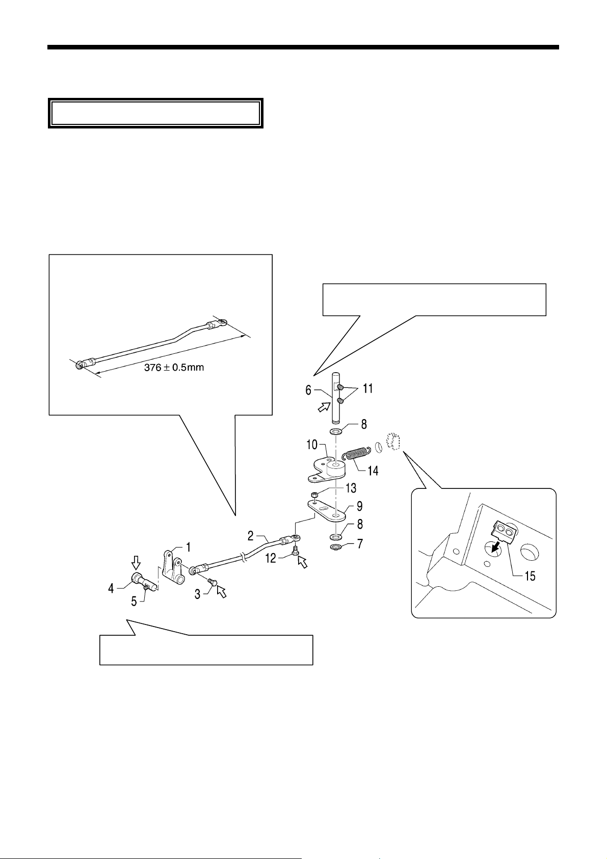
6. ASSEMBLY
r
±
y
A
6. ASSEMBLY
ssemble each part in order of the numbers.
Apply grease to the required places when reassembling the parts and once every two years.
6-1. Thread trimmer mechanism (1)
Apply grease <GREASE BZL-301 (SA2694-001)> specified by Brother to the portions indicated by the white arrows.
When the ball joint assembly of thread trimmer rod
H has been disassembled, assemble it so that the
distance between the centers of the holes is 376
0.5 mm.
5134Q
Tighten the set screw on the screw flat while
lightly pressing the movable knife lever shaft.
1. Movable knife leve
2. Thread trimmer rod H
3. Shoulder screw
4. Movable knife lever shaft
5. Set screw
6. Thread trimmer lever shaft
7. Retaining ring, C
8. Spacers [2 pcs]
Tighten the set screw on the screw flat while lightl
pressing the thread trimmer lever shaft.
9. Thread trimmer lever H
10. Thread trimmer lever V
11. Set screws [2 pcs]
12. Shoulder screw B
13. Nut
14. Spring
15. Spring hook
5135Q
58
BAS-311G, BAS-326G
Page 66

r
f
t
f
w
r
r
A
Tighten the set screw on the scre
flat while lightly pressing the colla
shaft.
Check that the thread trimmer colla
turns smoothly.
4853Q
Apply grease.
16. Driving leve
17. Thread trimmer collar
18. Collar shaft
19. Retaining ring, E
20. Set screw
21. Thread trimmer rod V
22. Shoulder screw B
23. Nut
24. Guide shaft
25. Spring
26. Cushion
27. Set screw
28. Thread trimmer solenoid
29. Solenoid setting plate
30. Plain washers [2 pcs]
31. Spring washers [2 pcs]
32. Bolts [2 pcs]
ssemble so that the wick is
hanging down.
33. Solenoid cushion
34. Washer
35. Solenoid lever
36. Set screw
37. Bolts with washer [2 pcs]
38. Pushing lever
39. Shoulder screw
40. Set screw
41. Nut
42. Connecting plate
43. Shoulder screw
44. Shoulder screw B
45. Nut
46. Plain washer
47. Spring washer
48. Bolt
6. ASSEMBLY
5136Q
When the ball joint assembly o
thread trimmer rod V has been
disassembled, assemble it so tha
the distance between the centers o
the holes is 287.5 ± 0.5 mm.
4615Q
BAS-311G, BAS-326G
59
Page 67
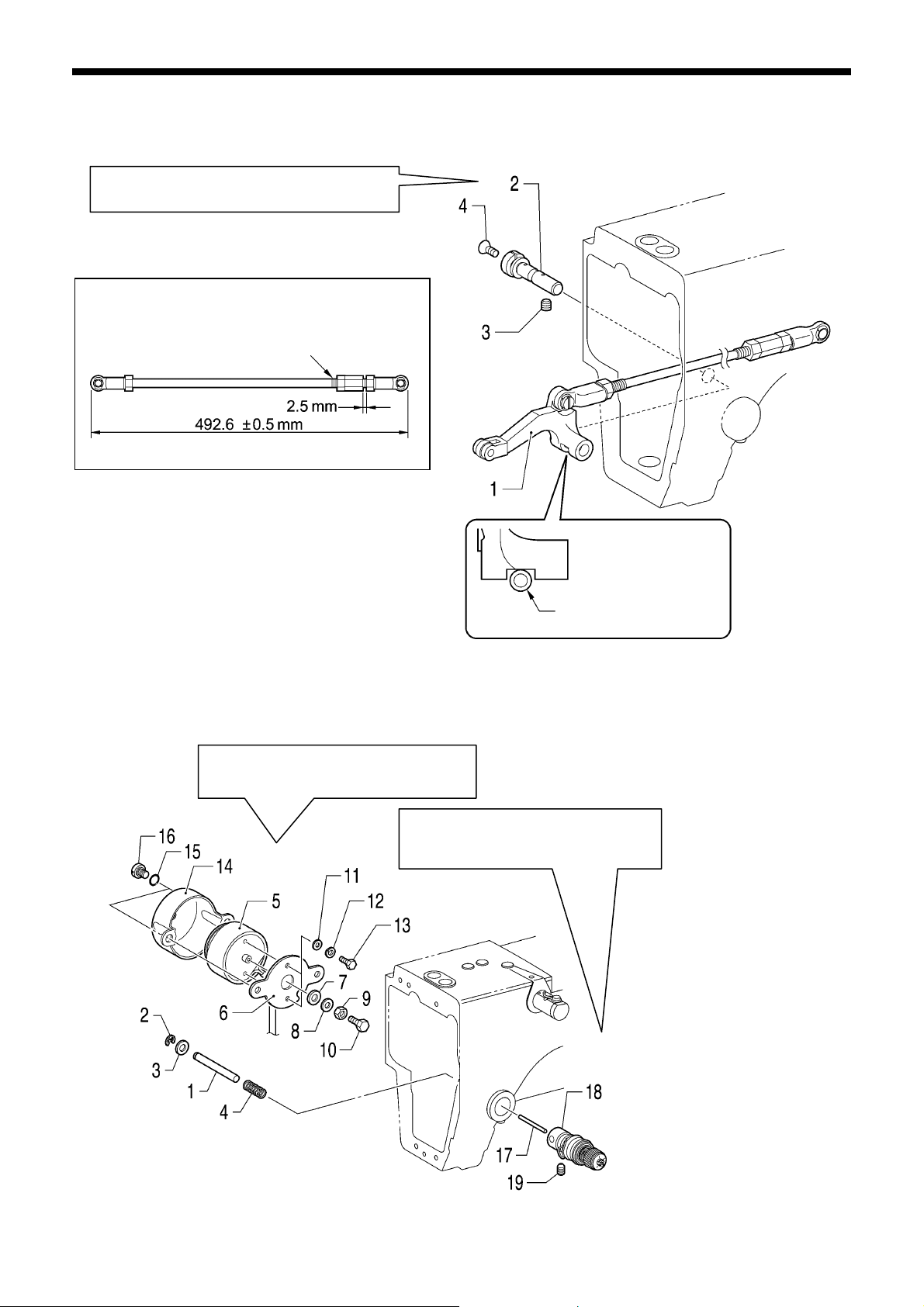
6. ASSEMBLY
r
A
A
6-2. Intermittent presser foot lifter mechanism (1)
Tighten the set screw on the screw flat while
lightly pressing the stepping clamp lifter shaft.
<Stepping clamp lifter rod adjustment>
Screw the stepping clamp lifter rod in as far as
it will go, then turn it back 3 times.
1. Stepping clamp lifter (Insert from the front)
2. Stepping clamp lifter shaft
3. Set screw
4. Flat screw
5138Q
Place the oil tube into
the groove.
5137Q
6-3. Tension release mechanism
5139Q
djust while referring to “7-18. Adjusting
the tension release amount”.
djust the thread take-up spring
height while referring to “7-2. Standard
thread tension”.
1. Tension release ba
2. Retaining ring, E
3. Plain washer
4. Spring
5. Tension release solenoid
6. Solenoid setting plate
7. Solenoid cushion
8. Plain washer
9. Nut
10. Bolt
11. Plain washers [2 pcs]
12. Spring washers [2 pcs]
13. Bolts [2 pcs]
14. Solenoid cover
15. O rings [2 pcs]
16. Shoulder screws [2 pcs]
17. Tension release pin
18. Tension bracket
19. Set screw
60
BAS-311G, BAS-326G
Page 68
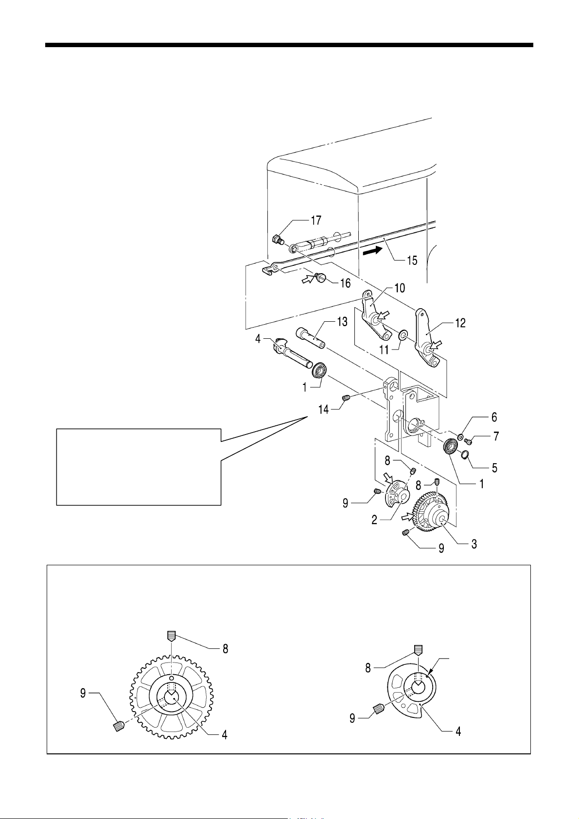
6. ASSEMBLY
A
r
r
6-4. Work clamp lifter mechanism (Solenoid specifications)
Apply grease <GREASE BZL-301 (SA2694-001)> specified by Brother to the portions indicated by the white arrows.
1. Ball bearings [2 pcs]
2. Work clamp cam
3. Work clamp cam gear
4. Work clamp fulcrum shaft
5. Retaining ring C
6. Plain washer
7. Screw
8. Set screws [2 pcs]
9. Set screws [2 pcs]
10. Work clamp driving lever
11. Plain washer
12. Stepping foot driving lever
13. Work clamp lever shaft
14. Set screw
15. Work clamp lifter link (Insert from the back)
16. Link shoulder screw
17. Shoulder screw
lign the screw stop, and then tighten
the screw so that there is no play in
the work clamp driving lever and the
stepping foot driving lever.
Check that the work clamp driving
lever and stepping foot driving leve
turn smoothly.
1) Set the work clamp cam gear so that there is no
clearance between it and the ball bearing in the
shaft direction, and then align the V groove in the
work clamp fulcrum shaft with the thread on the
hole side of the work clamp cam gear. Then tighten
the set screw.
2) Set the work clamp cam so that there is no
clearance between it and the work clamp cam gea
in the shaft direction, and then align the V groove in
the work clamp fulcrum shaft with the index mark on
the work clamp cam. Then tighten the set screw.
3) Lastly, tighten the two set screws (9).
Index mark
5159Q
5161Q5160Q
BAS-311G, BAS-326G
61
Page 69
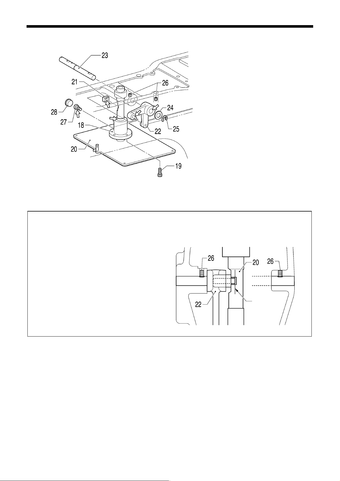
6. ASSEMBLY
A
t
5162Q
Place the slide block onto the pin of the work clamp
lifter lever. The pin and the surface of the slide
block should be aligned.
While aligning the slide block with the groove in the
work clamp lifter plate assembly, pass the work clamp
lever shaft B through the work clamp lifter lever.
NOTE:
When the work clamp lifter plate assembly is
lowered, the slide block moves away, so hold the
work clamp lifter plate assembly in place until the
link shoulder screw is tightened.
18. Slide bush
19. Bolts [4 pcs]
20. Work clamp lifter plate assy
21. Slide block
22. Work clamp lifter lever
23. Work clamp lever shaft B
24. Plain washer
25. Retaining ring E
26. Set screws [2 pcs]
27. Link shoulder screw
28. Rubber cap
lign the set screw with the screw stop and then tighten it so
that there is no play in the work clamp lifter lever. Check tha
the work clamp lifter lever moves smoothly.
Align
5163Q
62
BAS-311G, BAS-326G
Page 70
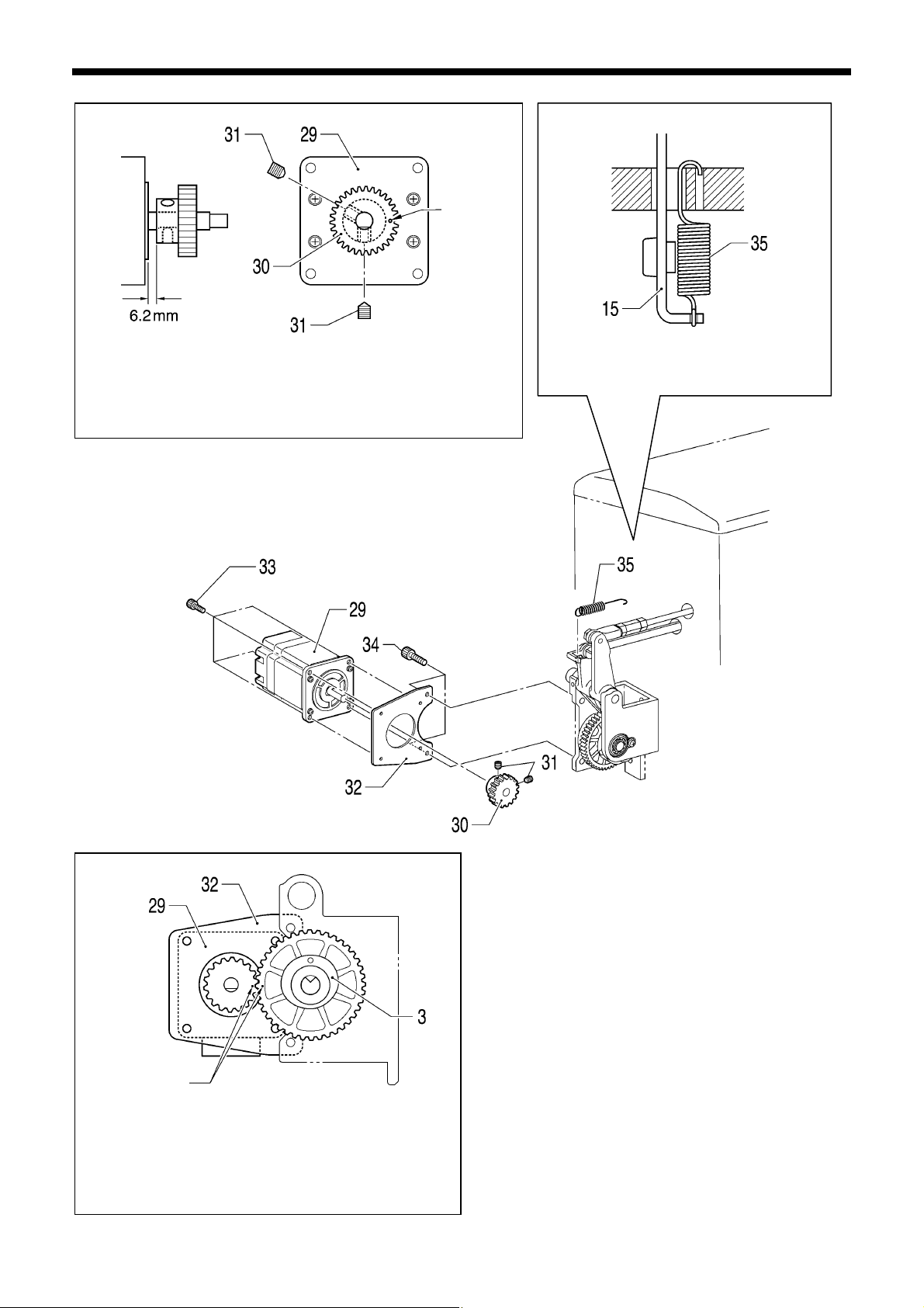
r
r
r
r
r
t
k
1) With the screw stop of the work clamp pulse motor facing
downward and the index mark on the work clamp driving gea
facing to the right, adjust so that the clearance between the
work clamp pulse motor and the work clamp driving gear is 6.2
mm, and then tighten the two set screws.
Index mark
Index mar
2) Install the work clamp pulse motor to the work clamp
motor plate with the four bolts so that the moto
connector is facing downward.
3) Align the index marks on the work clamp cam gea
and the work clamp driving gear, and then install the
work clamp motor plate with the two bolts so tha
there is no backlash.
5167Q
5164Q
6. ASSEMBLY
5165Q
Hook the spring into the arm hole as shown
in the illustration.
5166Q
29. Work clamp pulse moto
30. Work clamp driving gea
31. Set screws [2 pcs]
32. Work clamp motor plate
33. Bolts [4 pcs]
34. Bolts [2 pcs]
35. Work clamp spring
BAS-311G, BAS-326G
63
Page 71
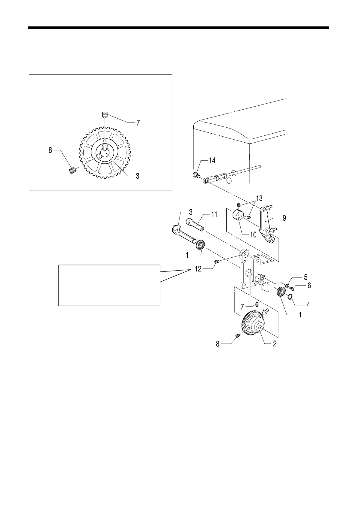
6. ASSEMBLY
A
t
6-5. Work clamp lifter mechanism (Pneumatic specifications)
Apply grease <GREASE BZL-301 (SA2694-001)> specified by Brother to the portions indicated by the white arrows.
Set the work clamp cam gear so that there is no
clearance between it and the ball bearing in the shaf
direction, and then align the V groove in the work clamp
fulcrum shaft with the thread on the hole side of the
work clamp cam gear. Then tighten the set screw.
lign the screw stop, and then tighten
the screw so that there is no play in
the stepping foot driving lever and the
set screw collar.
Check that the stepping foot driving
lever turns smoothly.
1. Ball bearings [2 pcs]
2. Work clamp cam gear
3. Work clamp fulcrum shaft
4. Retaining ring C
5. Plain washer
6. Screw
7. Set screw
8. Set screw
9. Stepping foot driving lever
10. Set screw collar
11. Work clamp lever shaft
12. Set screw
13. Set screws [2 pcs]
14. Shoulder screw
5168Q
5169Q
64
BAS-311G, BAS-326G
Page 72
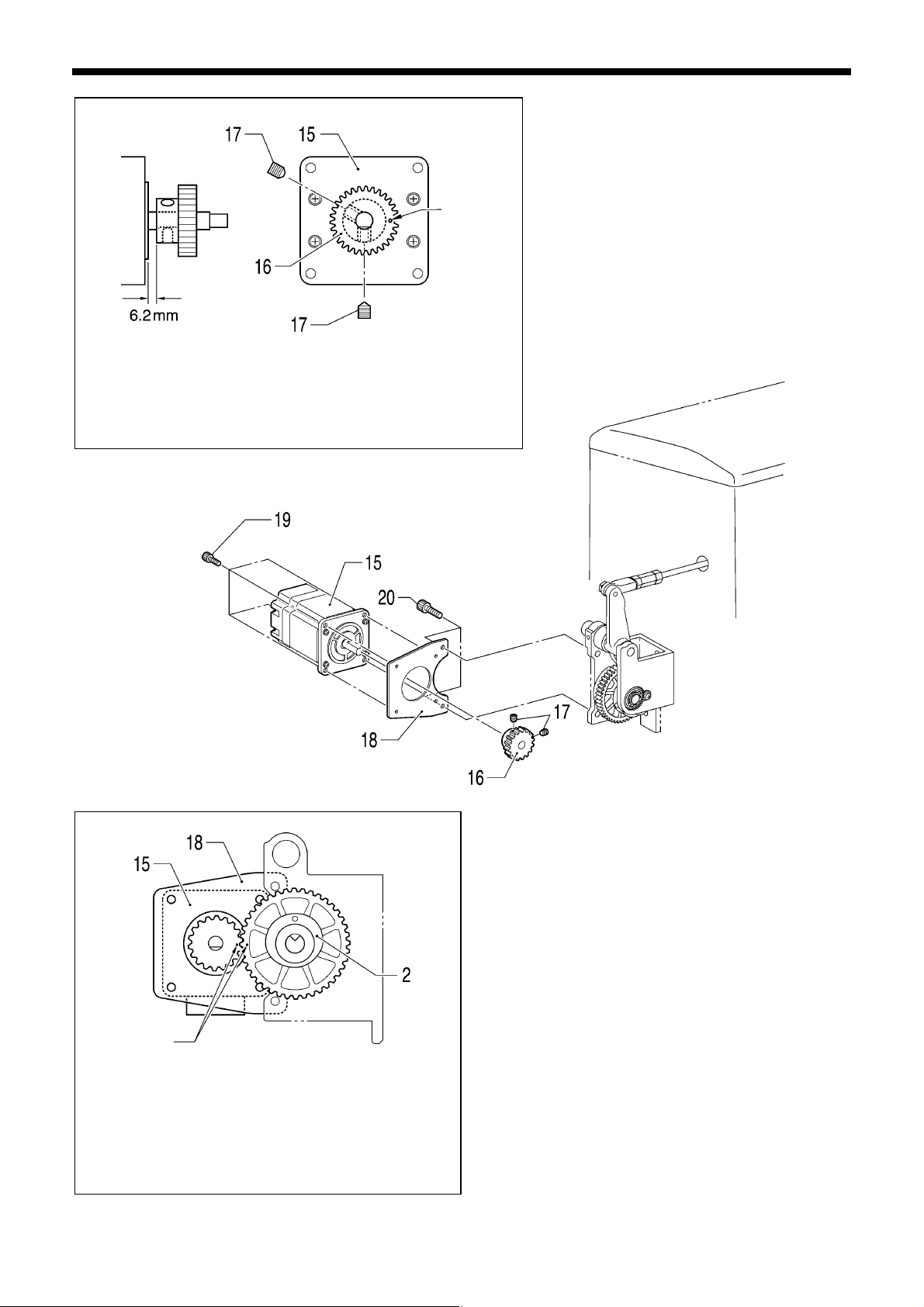
r
r
r
r
t
1) With the screw stop of the work clamp pulse motor facing
downward and the index mark on the work clamp driving gea
facing to the right, adjust so that the clearance between the
work clamp pulse motor and the work clamp driving gear is 6.2
mm, and then tighten the two set screws.
Index mark
Index mark
2) Install the work clamp pulse motor to the work clamp
motor plate with the four bolts so that the moto
connector is facing downward.
3) Align the index marks on the work clamp cam gea
and the work clamp driving gear, and then install the
work clamp motor plate with the two bolts so tha
there is no backlash.
5171Q
6. ASSEMBLY
5170Q
5172Q
15. Work clamp pulse moto
16. Work clamp driving gear
17. Set screws [2 pcs]
18. Work clamp motor plate
19. Bolts [4 pcs]
20. Bolts [2 pcs]
BAS-311G, BAS-326G
65
Page 73
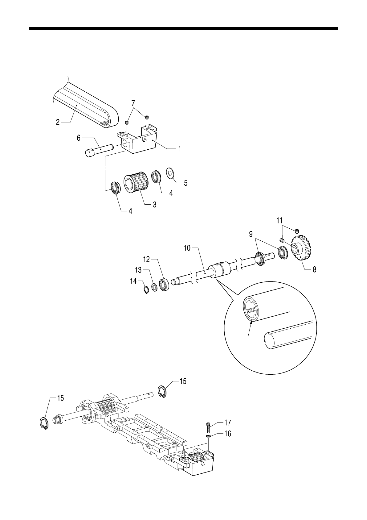
6. ASSEMBLY
r
A
t
6-6. Feed mechanism
Apply grease (AFC manufactured by THK or equivalent) to the areas indicated by the white arrows.
5173Q
8. X-feed gea
9. Ball bearings [2 pcs]
10. Y-ball spline
11. Set screws [2 pcs]
12. Ball bearing
13. Plain washer
14. Retaining ring C
5175Q
NOTE:
lign the ridges in the packing of the nu
with the grooves in the shaft when inserting
the shaft. If they are not aligned, the steel
balls inside the nut will fall out.
1. X-pulley bracket
2. X-GT belt
3. X-right pulley assy
4. Ball bearings [2 pcs]
5. Plain washer
6. X-pulley fulcrum shaft
7. Set screws [2 pcs]
Packing
15. Retaining rings C [2 pcs]
16. Plain washers [2 pcs]
17. Bolts [2 pcs] (Temporarily tighten)
5174Q
66
BAS-311G, BAS-326G
Page 74

Engage.
Push the X-LM guide against the
positioning pins of the feed
bracket and then tighten the
bolts.
Install the X-belt holder in between the X-LM guides as
shown in the diagram.
5215Q
Provisionally tighten the bolts so
that their heads do not protrude
from the top of the X-LM guide on
the inside.
18. Y-LM spacers [2 pcs]
19. Flat screws [16 pcs]
20. Y-LM guides [2 pcs]
21. Plain washers [8 pcs]
22. Spring washers [8 pcs]
23. Bolts [8 pcs]
24. X-LM guide [2 pcs]
25. Bolts [8 pcs]
6. ASSEMBLY
5176Q
5177Q
26. Feed bracket X
27. Bolts M3X6 [8 pcs]
28. Bolts M4X8 [2 pcs]
29. Flat screws [8 pcs]
30. X-belt holder
31. X-belt holder plate
32. Bolts [2 pcs]
BAS-311G, BAS-326G
67
Page 75

6. ASSEMBLY
t
33. Y-pulley bracket
34. Ball bearings [2 pcs]
35. Y-pulley assy
36. Y-GT belt
37. Y-pulley fulcrum shaft
38. Set screws [2 pcs]
39. Y-belt support plate
40. Y-belt presser plate
Place the Y-LM guide against the
wall of the bed, and then tighten
the bolts.
5179Q
Engage.
41. Bolts [4 pcs]
42. Y-pulley assy
43. Y-pulley collar
44. Ball bearings [2 pcs]
45. Y-feed gear
46. Y-pulley driving shaft
47. Retaining ring E
48. Set screws [4 pcs]
5178Q
Provisionally tighten the bolts so
that their heads do not protrude
from the top of the Y-LM guide a
the right.
49. Washers [4 pcs]
50. Bolts [4 pcs]
51. Bolts [4 pcs]
52. Bolts with washers [2 pcs]
(Temporarily tighten)
68
BAS-311G, BAS-326G
Page 76

6. ASSEMBLY
–
–
Install so that the backlash is 0.01
0.05.
5180Q
Install so that the backlash is 0.01
0.05.
53. X-feed motor assy
54. Bolts with washer [3 pcs] (Temporarily tighten)
55. Y-feed motor L assy
56. Bolts with washer [3 pcs] (Temporarily tighten)
57. Y belt cover
58. Screws with washer [4 pcs]
59. Oil cover
60. Screws [5 pcs]
61. Flat screws [3 pcs]
5181Q
BAS-311G, BAS-326G
69
Page 77

6. ASSEMBLY
<X-GT belt tension adjustment>
Measurement position
5183Q
1. Move the X feed bracket (1) so that it is in the middle of the sewing area in the Y direction and at the left edge of the
sewing area in the X direction.
2. Loosen the two bolts (3) of the X-pulley bracket (2), and then provisionally tighten them at 19.6 mN·m.
3. Pass the M5x25 screw through the countersunk hole in the side of the bed and screw it into the tap hold in the X-pulley
bracket (2). Then adjust the belt tension to the following value.
[For a new belt: 290 – 330 N; For a reused belt: 220 – 250 N]
4. Tighten the two bolts (3), and then remove the M5x25 screw.
5. Measure the belt tension once more and check that it is at the following value.
[For a new belt: 400 – 440 N; For a reused belt: 320 – 350 N]
* Be sure to use a belt tension gauge to measure the belt tension, and measure from the bottom of the belt.
* The belt tension gauge should be set to measure a unit weight of 0.04 kg/m, a belt width of 30 mm and a span length of
370 mm.
* The recommended belt tension gauge to use is the Dr. TENSION TYPE-ll manufactured by MITSUBOSHI BELTING
LTD.
70
BAS-311G, BAS-326G
Page 78

6. ASSEMBLY
<Y-GT belt tension adjustment>
Measurement position
5184Q
1. Move the X feed bracket (1) so that it is in the middle of the sewing area in the Y direction and at the left edge of the
sewing area in the X direction.
2. Loosen the two bolts (3) of the Y-pulley bracket (2), and then provisionally tighten them at 19.6 mN·m.
3. Pass the M5x25 screw through the countersunk hole in the side of the bed and screw it into the tap hold in the Y-pulley
bracket (2). Then adjust the belt tension to the following value.
[For a new belt: 250 – 320 N; For a reused belt: 160 – 240 N]
4. Tighten the two bolts (3), and then remove the M5x25 screw.
5. Measure the belt tension once more and check that it is at the following value.
[For a new belt: 500 – 600 N; For a reused belt: 400 – 480 N]
* Be sure to use a belt tension gauge to measure the belt tension, and measure from the bottom of the belt.
* The belt tension gauge should be set to measure a unit weight of 0.04 kg/m, a belt width of 30 mm and a span length of
370 mm.
* The recommended belt tension gauge to use is the Dr. TENSION TYPE-ll manufactured by MITSUBOSHI BELTING
LTD.
BAS-311G, BAS-326G
71
Page 79

6. ASSEMBLY
<Inside X-LM guide installation>
<Right Y-LM guide installation>
5185Q
5186Q
1. With tension applied to the X-GT belt and the X-feed
motor assembly installed, use a push-pull tension
gauge to push the X feed bracket (1) from one edge
to the other in the X direction.
2. Tighten the eight bolts (2) at the place where the load
is 29 – 59 N (variation within 20 N).
1. With tension applied to the Y-GT belt and the Y-feed
motor L assembly installed, use a push-pull tension
gauge to push the X feed bracket (1) from one edge
to the other in the Y direction.
2. Tighten the two bolts (2) at the place where the load
is 39 – 78 N (variation within 20 N).
72
BAS-311G, BAS-326G
Page 80
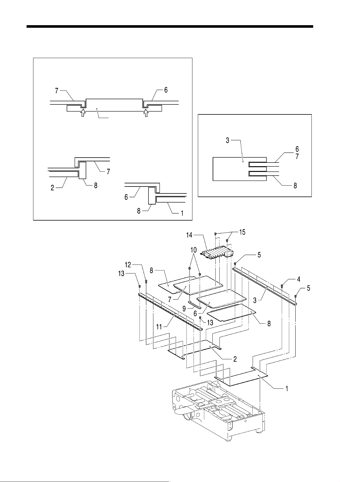
r
r
6-7. Feed covers
1) Place the inside cover into the groove in the X feed bracket.
Apply grease (MOLYKOTE LONGTERM W2 manufactured
by Dow Corning or equivalent) to the areas indicated by the
white arrows.
Feed bracket X
2) Set so that the rubber part of the inside cover is on the
outside of the rubber part of the outside cover and so that the
stopper of the inside cover is on the inside of the fixed cover.
5188Q 5189Q
1. Fixed cover R
2. Fixed cover L
3. Cover rail
4. Screws M4X10 [6 pcs]
5. Screws M4X4 [2 pcs]
6. Inside cover R assy (Place into cover rail.)
7. Inside cover L assy (Place into cover rail.)
8. Outside cover assemblies [2 pcs]
(Place into cover rail.)
9. Cover connecting plate
10. Screws [2 pcs]
11. Cover rail
12. Screws M4X10 [6 pcs]
13. Screws M4X4 [2 pcs]
14. Bellow assy
15. Screws [4 pcs]
6. ASSEMBLY
Place the inside cover into the upper cove
rail, and place the outside cover into the lowe
cover rail.
5187Q
5190Q
BAS-311G, BAS-326G
73
Page 81
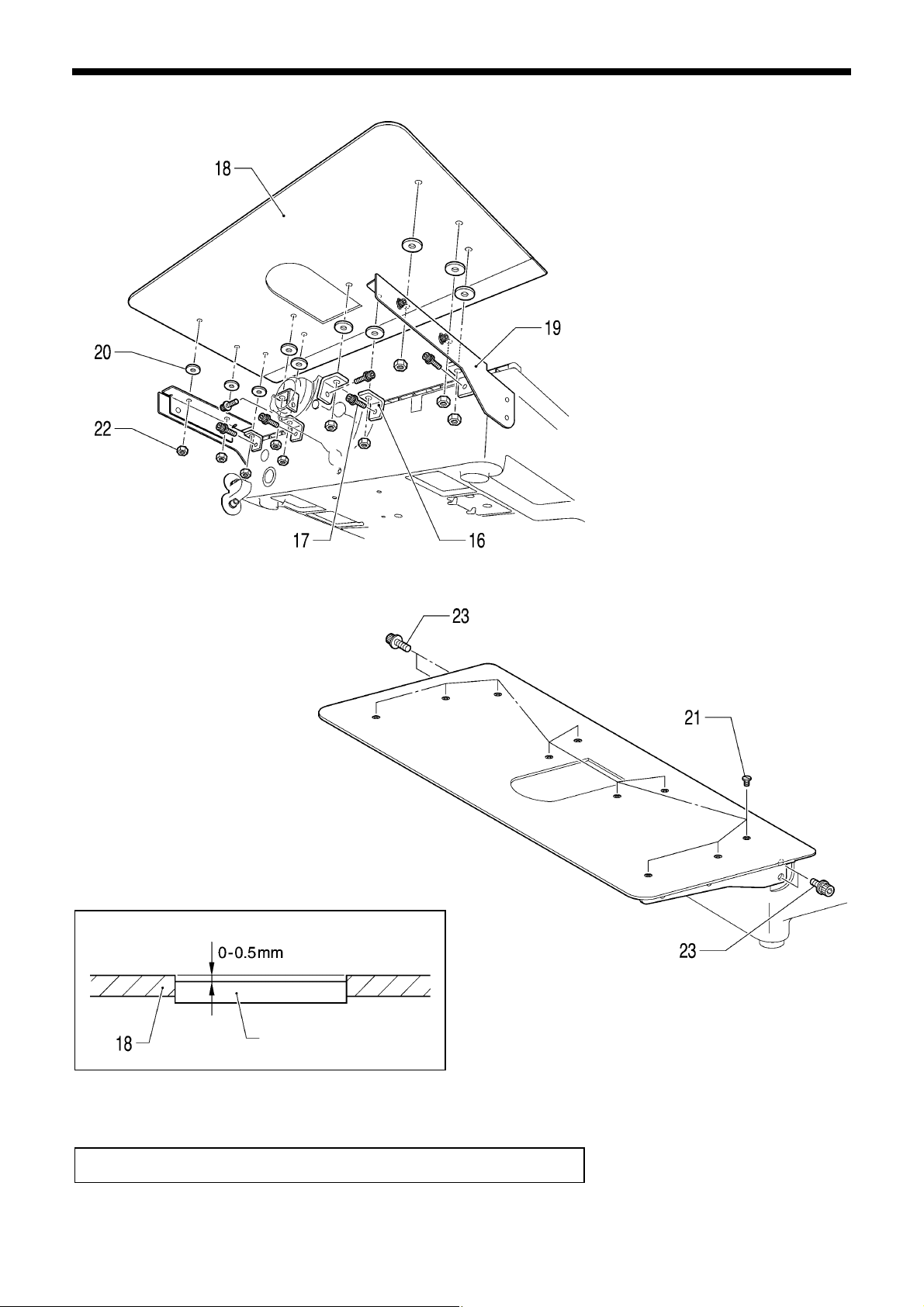
6. ASSEMBLY
A
5191Q
Needle plate
5193Q
fter installing, carry out the adjustments in "7-20-2. X-Y feed home position ".
5192Q
16. Auxiliary plate brackets [6 pcs]
17. Bolts with washer [6 pcs]
18. Auxiliary plate
19. Support plate guides [2 pcs]
20. Auxiliary plate cushions [10 pcs]
21. Screws [10 pcs] (Tighten to 0.5 N·m.)
22. Nuts [10 pcs]
23. Bolts with washer [4 pcs]
74
BAS-311G, BAS-326G
Page 82
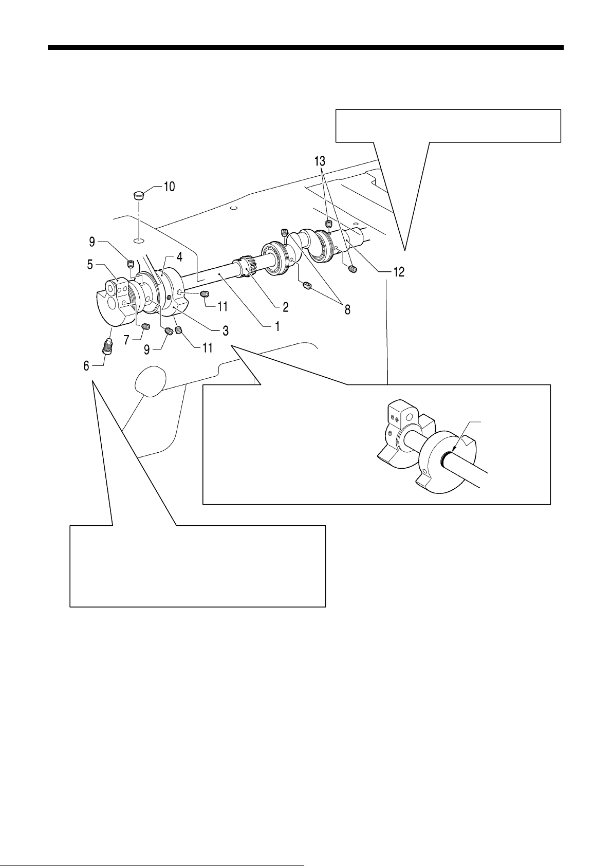
A
t
A
r
6-8. Upper shaft mechanism
1) Tighten the screw of the thread take-up crank so tha
it is aligned with the upper shaft hole.
2) While pressing the thread take-up crank so that there
is no play in it, tighten the two set screws (8).
pply adhesive (Threebond 1401 or similar) to the thread
section of the screw.
Install the bobbin winder driving
wheel so that it is in phase with the
thread take-up crank and aligned
with the reference line on the uppe
shaft.
6. ASSEMBLY
pply adhesive (Threebond 1324 or similar) to the
outside of the bearing of joint assy.
5140Q
Reference line
5204Q
1. Upper shaft
2. Pulley gear R
3. Bobbin winder driving wheel
4. Stepping clamp cam assy
5. Thread take-up crank
6. Screw
7. Set screw
8. Set screws [2 pcs]
9. Set screws [2 pcs]
10. Rubber cap
11. Set screws [2 pcs]
12. Joint assy
13. Set screws [2 pcs]
BAS-311G, BAS-326G
75
Page 83
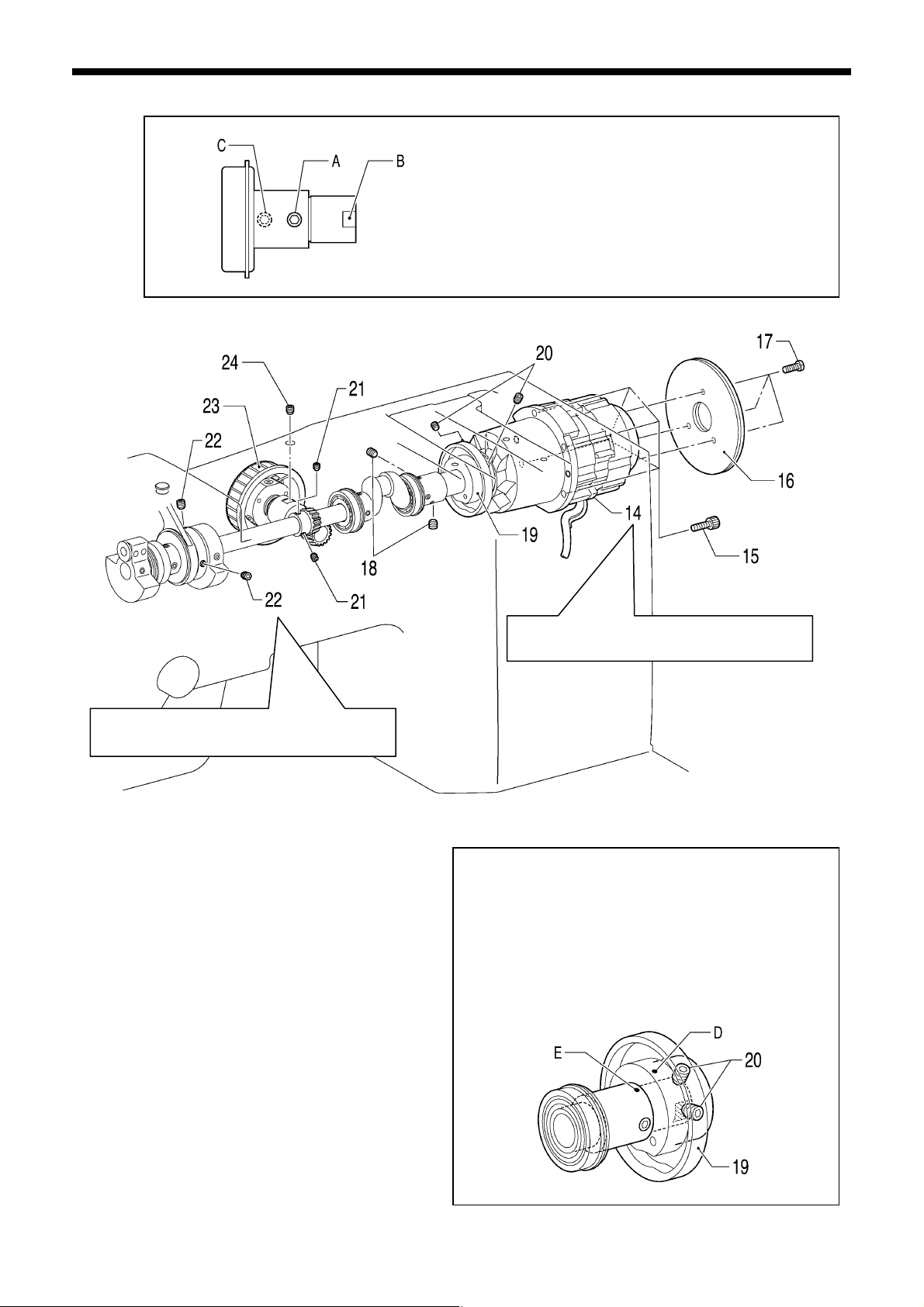
6. ASSEMBLY
k
A
A
t
djust while referring to “6-10. Intermitten
presser foot lifter mechanism (2)”.
14. Motor assy
15. Bolts [4 pcs]
16. Fries wheels [2 pcs]
17. Screws [3 pcs]
18. Set screws [2 pcs]
19. Thread trimmer cam
20. Set screws [2 pcs]
21. Set screws [2 pcs]
22. Set screws [2 pcs] (Temporarily tighten)
23. Pulley assy
24. Set screw
Tighten the set screw so that the screw stop A on the
motor shaft is in the same phase as the screw stop B on
the thread trimmer cam.
Tighten the set screw so that the screw stop C on the
upper shaft is at a phase of approximately 180 degrees
from the screw stop A on the motor shaft.
4644Q
Install the motor assembly so that the
harness is facing downward.
5141Q
1) Align the index mark D on the thread trimmer cam and
the index mark E on the joint assembly, and then
provisionally tighten the set screw at the index mar
side.
2) After tightening the set screw at the screw stop side,
fully tighten the set screw at the index mark side.
3) Carry out the adjustments in "7-17. Adjusting the
thread trimmer cam position".
pply the specified grease (GREASE BZL-301) to the
grooves.
5182Q
76
BAS-311G, BAS-326G
Page 84
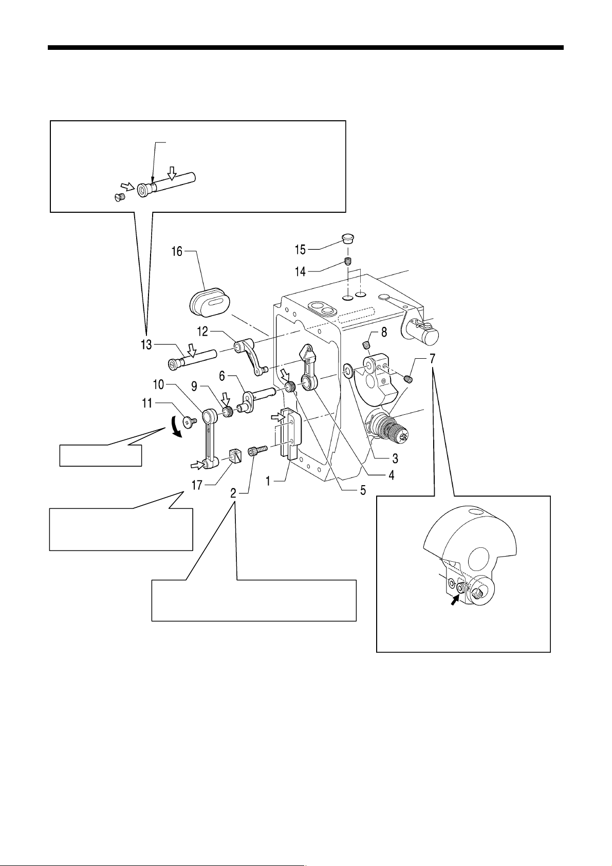
6. ASSEMBLY
r
A
y
6-9. Needle bar mechanism
Apply grease <GREASE BZL-301 (SA2694-001)> specified by Brother to the portions indicated by the white arrows.
Inside hole
Left-hand thread
Fit the chamfering side of the
slide block into the groove on
the slide block guide.
Set so that this hole faces upward, and
then push in gently while tightening the
set screw to install.
fter securing the needle bar, position the
slide block guide so that the machine pulle
turns smoothly, and then tighten the bolts.
1. Slide block guide
2. Bolts [2 pcs] (Temporarily tighten)
3. Washer
4. Thread take-up lever assy
5. Needle bearing
6. Needle bar crank
7. Set screws [2 pcs]
8. Set screw
9. Needle bearing
5142Q
While gently pushing the needle ba
crank in the shaft direction, align the
set screw with the screw stop and then
tighten the set screw.
10. Needle bearing
11. Screw
12. Thread take-up support
13. Thread take-up support shaft assy
14. Set screws [2 pcs]
15. Rubber caps [2 pcs]
16. Rubber cap
17. Slide block
BAS-311G, BAS-326G
77
Page 85
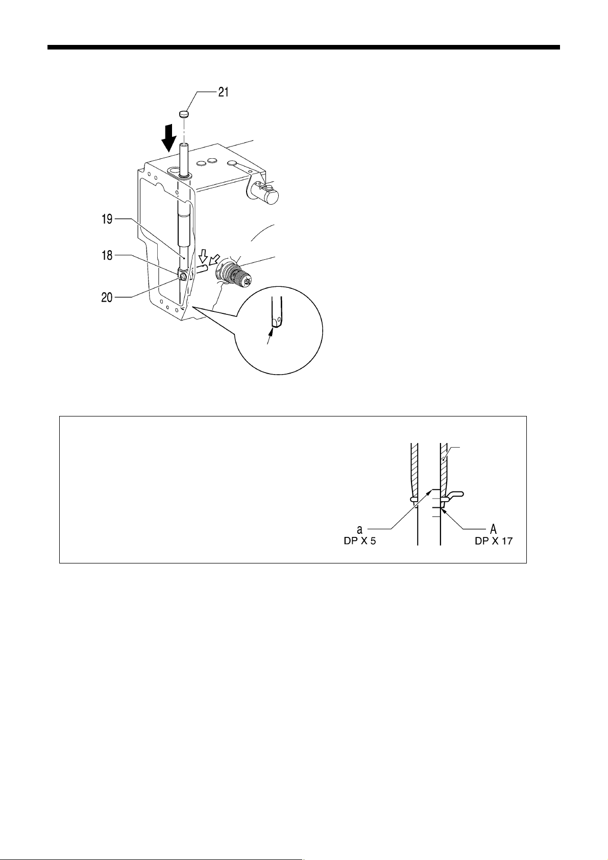
6. ASSEMBLY
A
Inside hole
Cut section
lign the needle bar so that reference line A (the second lowest
reference line on the needle bar) or reference line a (top reference
line) is aligned with the lower edge of the needle bar bush when the
machine pulley is turned to raise the needle bar from its lowest
position, and then set the cut section so that it is facing forward and
tighten the screw.
4647Q
18. Needle bar clamp
19. Needle bar (Insert from above)
20. Screw
21. Rubber cap
5143Q
Needle bar
bush
78
BAS-311G, BAS-326G
Page 86
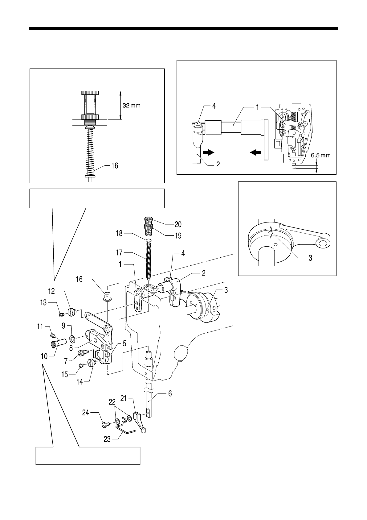
A
t
6-10. Intermittent presser foot lifter mechanism (2)
Install the presser bar spring collar as shown in the
illustration, and then adjust the height of the
presser adjusting screw to 32 mm.
Notes on the installation position
(Refer to “7-13. Changing the intermittent stroke”.)
Tighten the set screw on the screw fla
while lightly pressing the link shaft.
5194Q
5195Q
1) With the needle bar lowered approximately 6.5 mm from
its highest position, set the stepping clamp arm F to the
position of the straight line in the illustration.
2) Place a bushing in between stepping clamp arm F and
stepping clamp arm R so that there is no play, and then
tighten the bolt.
5196Q
6. ASSEMBLY
t the needle bar timing position,
align the index marks of the
stepping clamp cam and the
stepping clamp connecting rod, and
then tighten the set screw.
5197Q
1. Stepping clamp arm F
2. Stepping clamp arm R
3. Set screws [2 pcs]
4. Bolt
5. Presser bar clamp
6. Presser bar
7. Bolt (Temporarily tighten)
8. Stepping clamp lifter link
9. Washer
10. Link shaft (with retaining ring)
11. Set screw
12. Shoulder screw
13. Screw
14. Shoulder screw
15. Screw
16. Presser bar spring collar
17. Presser bar spring
18. Presser bar spring guide
19. Adjusting screw nut
20. Presser adjusting screw
21. Presser foot
22. Plain washers [2 pcs]
23. Finger guard
24. Screw (Temporarily tighten)
BAS-311G, BAS-326G
79
Page 87

6. ASSEMBLY
After installing the needle plate while referring to “6-13. Thread trimmer mechanism (2)”, carry out the following adjustments.
5198Q
5199Q
1. Turn the work clamp cam gear (1) to move the stepping foot driving lever (2) to the solid line position shown in the
illustration.
2. Loosen the two nuts (4) and turn the joint (5) to adjust the height of the roller (3) so that it is 155.5 mm above the top of
the needle plate.
3. Lower the needle bar approximately 6.5 mm from its highest position.
4. Set the height of the presser bar (6) to 41 mm above the needle plate, align the center of the presser foot (7) and the
needle hole, and then tighten the bolt (8).
5. Set the height of the presser foot (7) to 22 mm above the needle plate, and then tighten the screw (9).
6. Turn the work clamp cam gear (1) to move the stepping foot driving lever (2) to the dotted line position shown in the
illustration.
7. Set the needle bar to the timing position.
8. Loosen the nut (10) and turn the bolt (11) to set the height of the presser foot (7) to 0.5 mm above the needle plate.
80
BAS-311G, BAS-326G
Page 88
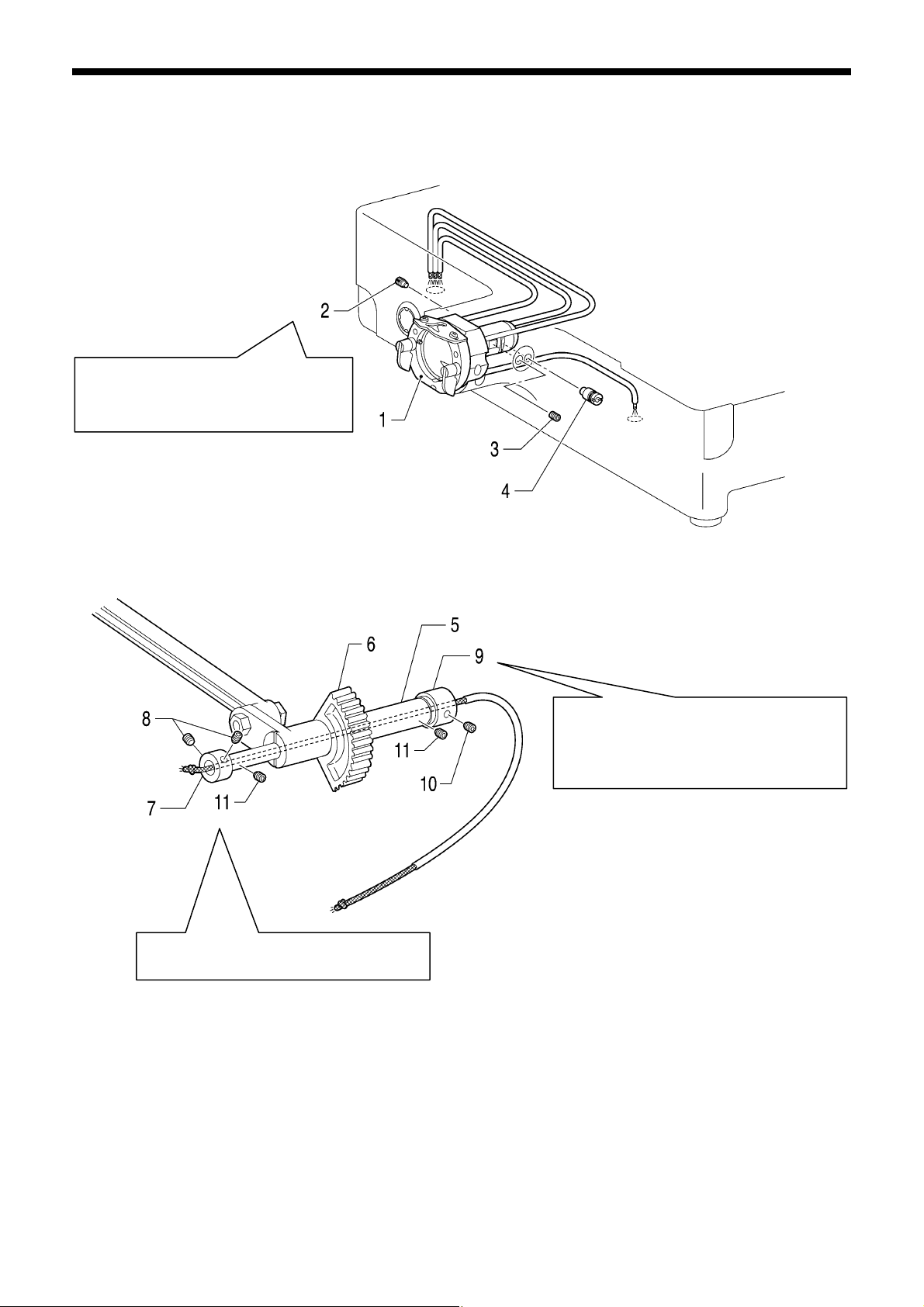
f
k
A
6-11. Lower shaft mechanism
Tighten the set screw until the head o
the screw is flush with the edge of the
bed. (Refer to “7-8. Rotary hoo
lubrication amount”.)
1. Shuttle race base assy
2. Set screw
3. Set screw
4. Adjusting stud
djust while referring to “7-19. Adjusting
the backlash of the lower shaft gear”.
6. ASSEMBLY
5144Q
While turning the machine pulley, move the
rock gear back and forth to the position
where it turns smoothly.
Place set screw collar R against the edge
of the bed and tighten the set screw.
5145Q
5. Rock gear shaft
(Insert from the rear of the machine head)
6. Rock gear
7. Set screw collar, B
8. Set screws [2 pcs]
9. Set screw collar, R
10. Set screw (Temporarily tighten)
11. Set screws [2 pcs] (Temporarily tighten)
BAS-311G, BAS-326G
81
Page 89

6. ASSEMBLY
k
y
5146Q
Provisionally tighten the bolt while lightl
pressing the driver against the retaining
ring.
Mating
mar
Insert the crank rod (lower part) into the crank of the
upper shaft, and then align the mating mark on the
crank rod (upper part) from above and gently tighten the
bolts.
* Check that the machine pulley turns smoothly.
12. Lower shaft assy
(Insert from the rear of the machine head)
13. Retaining ring E
14. Driver
15. Bolt (Temporarily tighten)
16. Adjusting stud
17. Set screw
18. Crank rod [Lower part] (Insert into upper shaft crank)
19. Needle bearing
20. Crank rod [Upper part] (Align the mating mark)
21. Bolts [2 pcs]
22. Crank cover
23. Screws [3 pcs]
5147Q
5148Q
82
BAS-311G, BAS-326G
Page 90

A
A
6-12. Shuttle hook mechanism
5149Q
fter installing the shuttle hook, carry out the adjustments in “7-4.
djusting the needle bar lift amount”, “7-5. Adjusting the driver needle
guard” and “7-6. Adjusting the needle clearance”.
6. ASSEMBLY
5150Q
1. Needle bar thread guide
2. Needle
3. Set screw
4. Shuttle hook
5. Shuttle race base
6. Shuttle race base setting claw (Close)
7. Bobbin
8. Bobbin case
6-13. Thread trimmer mechanism (2)
Apply grease <GREASE BZL-301 (SA2694-001)> specified by Brother to the portions indicated by the white arrows.
5151Q
1. Fixed knife
2. Plain washers [2 pcs]
3. Screws [2 pcs]
4. Movable knife spacer
5. Movable knife assy
6. Movable knife collar
7. Thrust washer
8. Movable knife shoulder screw
9. Needle plate
10. Screws [2 pcs]
11. Flat screws [2 pcs]
Movable knife
connecting plate
Insert the pin of the movable knife assembly into the
hole in the movable knife connecting plate, and then
install the needle plate with the screws and flat screws
so that the needle drops into the center of the needle
hole.
5152Q
BAS-311G, BAS-326G
83
Page 91

6. ASSEMBLY
A
6-14. Work clamp arm mechanism
Pneumatic specifications
5200Q
1. Feed plate
2. Bolts with washer [2pcs]
3. Work clamp assy
4. Plain washers [4 pcs]
5. Spring washers [4 pcs]
5201Q
fter installing, carry out test feeding and check that the needle hole is inside the work clamp and the feed plate
frame. If the needle hole is not inside the frame, adjust the position of the work clamp arm assembly and feed plate.
6. Bolts [4 pcs]
84
BAS-311G, BAS-326G
Page 92

6. ASSEMBLY
6-14-1. Adjustments after work clamp arm installation
Solenoid specifications
5202Q 5203Q
<Retainer adjustment>
1. Screw in the M4 tap (1) on the side of the work clamp arm to apply pressure.
2. Adjust so that the sliding load of the retainers (2) is 40 – 80 N.
<Work clamp height adjustment (Solenoid specifications)>
1. Set the work clamp height to “25” on the operation panel.
2. Loosen the bolt (3).
3. Set the height of the work clamp (4) to 25 mm above the top of the needle plate, and with the stopper (5) touching the
connecting link (6), tighten the bolt (3).
<Work clamp height adjustment (Pneumatic specifications)>
1. Raise the work clamp arm electronically.
2. Loosen the bolt (7), lift the work clamp lifter lever (8) by hand to its maximum height, and then tighten the bolt (7).
3. Loosen the nut (9) of the air cylinder.
4. Turn the shaft of the air cylinder until the work clamp (10) is 30 mm above the top of the needle plate, and then tighten
the nut (9).
<Work clamp adjustment>
1. Loosen the bolt (11).
2. Lower the work clamp arm electronically, and in that condition, tighten the work clamp (12) with the bolt (11).
<Work clamp pressure adjustment>
1. Loosen the nut (13), and tighten the set screw (14).
(Up to a maximum of 0.3 mm)
2. When the work clamp pressure is even at the front and back of the work clamp, tighten the nut (13).
Pneumatic specifications
BAS-311G, BAS-326G
85
Page 93

6. ASSEMBLY
A
A
t
6-15. Thread wiper mechanism
lign the thread wiper shaft bracke
and the bottom of the arm and then
tighten the two bolts with washer.
1. Thread wiper unit
2. Bolts with washer [2 pcs]
3. Bolt (Remove)
4. Plain washer (Remove)
5. Removed plain washer
6. Removed bolt
7. STOP switch harness
8. Thread wiper solenoid harness
djust the thread wiper after installing. (Refer to “7-11. Adjusting the thread wiper”.)
5153Q
86
BAS-311G, BAS-326G
Page 94

r
6-16. Covers
1. Shuttle race cove
2. Screws [2 pcs]
3. Face plate assy
4. Screws [3 pcs]
5. Eye guard assy
6. Plain washers [2 pcs]
7. Screws [2 pcs]
assy
8. Motor cover L
9. Screws [4 pcs]
10. Motor cover R
11. Screws [4 pcs]
12. Motor cover
13. Screws [4 pcs]
14. Top cover
15. Screws [6 pcs]
6. ASSEMBLY
5154Q
BAS-311G, BAS-326G
87
Page 95

7. ADJUSTMENT
7. ADJUSTMENT
CAUTION
Maintenance and inspection of the sewing machine
should only be carried out by a qualified technician.
Ask your Brother dealer or a qualified electrician to
carry out any maintenance and inspection of the
electrical system.
Turn off the power switch and disconnect the power
cord before carrying out the following operations.
If the foot switch is depressed by mistake, the sewing
machine might start operating and injury could result.
• Inspection, adjustment and maintenance
• Replacing consumable parts such as the rotary
hook
7-1. Checking the machine head switch
Check that the machine head switch is turned on as shown
in the illustration.
NOTE:
5226Q
Hold the machine head with both hands when tilting it
back or returning it to its original position.
In addition, do not apply excessive force when tilting
back the machine head. The sewing machine may
become unbalanced and fall down, and serious injury
or damage to the sewing machine may result.
If the power switch needs to be left on when carrying
out some adjustment, be extremely careful to
observe all safety precautions.
If any safety devices have been removed, be
absolutely sure to re-install them to their original
positions and check that they operate correctly
before using the machine.
If the machine head switch is not turned on, errors
"E050", "E051" and "E055" will be generated.
88
BAS-311G, BAS-326G
Page 96
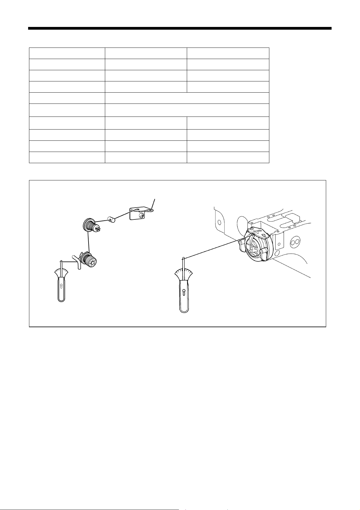
7-2. Standard thread tension
Specifications Heavy-weight materials (-01) Medium-weight materials (-02)
Upper thread #20 or similar #50 or similar
Lower thread #20 or similar #50 or similar
7. ADJUSTMENT
Upper thread tension (N)
Lower thread tension (N)
Thread take-up spring height
(mm)
Thread take-up spring
tension (N)
Pre-tension (N)
Needle DP x 17 #19 DP x 5 #16
Normal sewing speed 2,000 rpm 2,000 rpm
1.4 − 1.8 0.8 − 1.2
0.2 − 0.3
7 − 10
0.6 − 1.2 0.2 − 0.5
0.1 − 0.6 0.1 − 0.3
7-2-1. Upper and lower thread tension
5155Q4661Q
BAS-311G, BAS-326G
89
Page 97
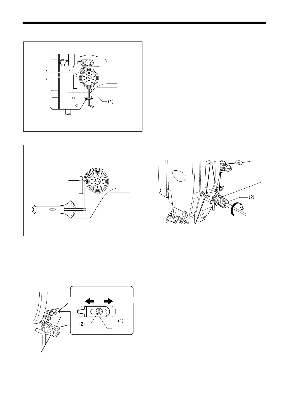
7. ADJUSTMENT
Q
7-2-2. Thread take-up spring
Lower
<Thread take-up spring tension>
4664Q
Turn the tension stud (2) with a screwdriver to adjust the tension.
Higher
5022Q
<Thread take-up spring height>
Loosen the set screw (1) and turn the adjuster to adjust.
Stronger
Weaker
5023Q
NOTE:
If the thread tension spring is not adjusted correctly, the upper thread trailing length will be uneven after thread trimming.
7-2-3. Arm thread guide R
The standard position of arm thread guide R (1) is when the
screw (2) is aligned with the index mark.
Loosen the screw (2) and move arm thread guide R (1) to
adjust.
* When sewing heavy material, move arm thread guide R
(1) to the left. (The thread take-up amount will become
greater.)
* When sewing light material, move arm thread guide R (1)
to the right. (The thread take-up amount will become less.)
90
More thread
Less thread
Index mark
5030
BAS-311G, BAS-326G
Page 98
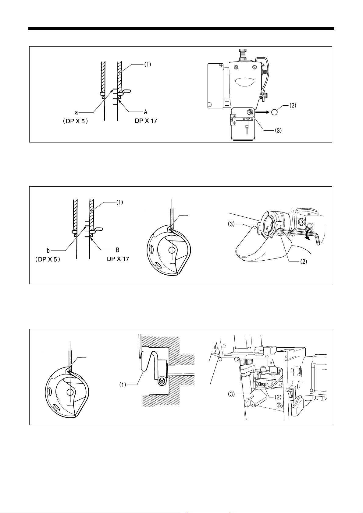
7. ADJUSTMENT
7-3. Adjusting the needle bar height
2552Q 4992Q
Turn the machine pulley to move the needle bar to the lowest position. Then remove the rubber plug (2), loosen the screw
(3) and then move the needle bar up or down to adjust so that the second reference line from the bottom of the needle bar
(reference line A) is aligned with the lower edge of the needle bar bush (1).
* If using a DP X 5 needle, use the highest reference line (reference line a).
7-4. Adjusting the needle bar lift amount
2554Q 4993Q
Turn the machine pulley to raise the needle bar from the lowest position until the lowest reference line on the needle bar
(reference line B) is aligned with the lower edge of the needle bar bush (1), and then loosen the bolt (2) and move the driver
(3) so that the tip of the rotary hook is aligned with the center of the needle.
* If using a DP X 5 needle, use the second reference line from the top of the needle bar (reference line b).
Needle center
Rotary hook tip
0135Q
7-5. Adjusting the driver needle guard
Turn the machine pulley to align the tip of the rotary hook with the center of the needle, and then loosen the set screw (2)
and turn the eccentric shaft (3) to adjust so that the driver needle guard (1) is touching the needle.
NOTE:
Needle center
Rotary hook tip
2555Q
5227Q 0135Q
If it crosses the needle more than necessary, it will place a load on the needle, or it may cause poor thread tension.
Furthermore, if it does not cross the needle at all, the tip of the rotary hook will interfere with the needle and skipped
stitches may occur.
BAS-311G, BAS-326G
91
Page 99
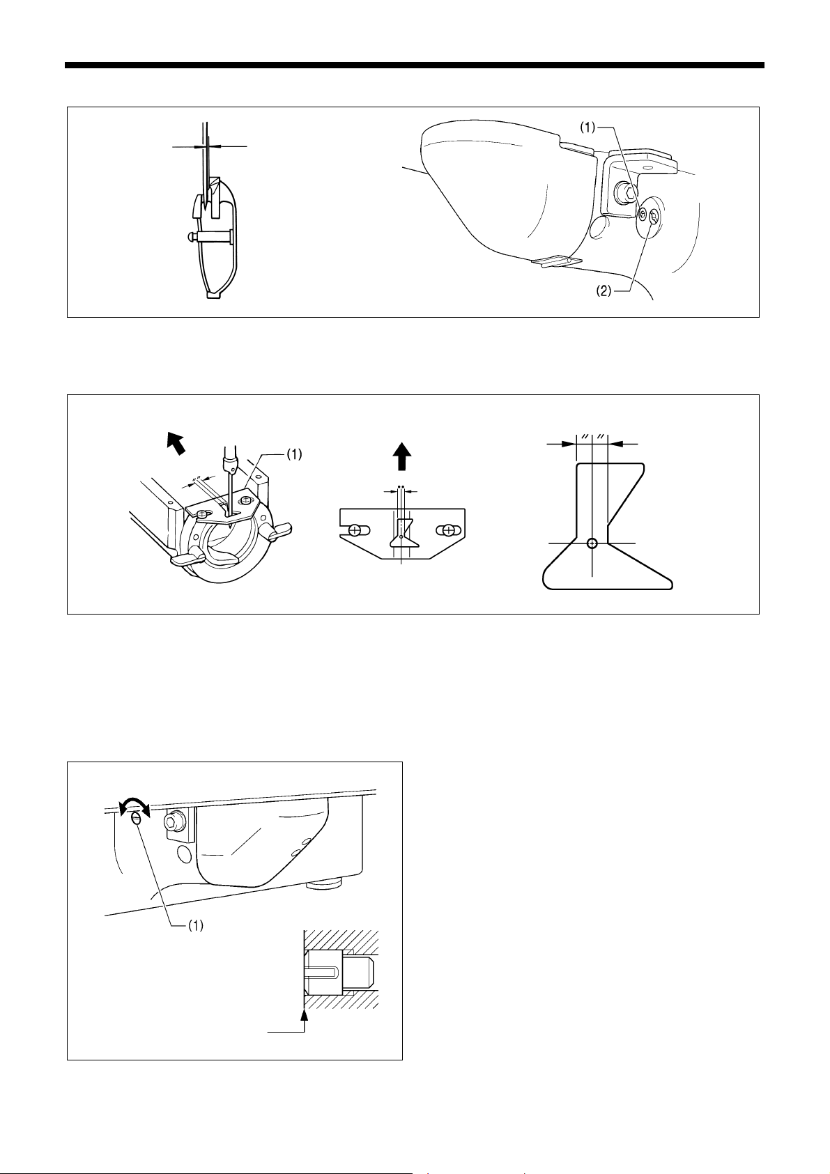
7. ADJUSTMENT
7-6. Adjusting the needle clearance
0138Q 4995Q
Turn the machine pulley to align the tip of the rotary hook with the center of the needle, and then loosen the set screw (1)
and turn the eccentric shaft (2) to adjust so that the clearance between the needle and the rotary hook is 0.01 − 0.08 mm.
0.01 − 0.08mm
7-7. Adjusting the shuttle race thread guide
3574Q
Install the shuttle race thread guide (1) by pushing it in the direction of the arrow so that the needle groove is aligned with
the center of the needle plate hole.
NOTE:
If the shuttle race thread guide is in the wrong position, thread breakages, soiled thread or tangling of the thread may
occur.
The position of the shuttle race thread guide is adjusted at the time of shipment from the factory. It should not be
changed if possible.
7-8. Rotary hook lubrication amount
The optimum position is when the head of the set screw (1)
Less oil More oil
Aligned
4996Q
is aligned with the edge of the bed. The rotary hook
lubrication amount can be adjusted within three turns to the
right from that position.
• If the set screw (1) is turned clockwise, the lubrication
amount becomes smaller.
• If the set screw (1) is turned counterclockwise, the
lubrication amount becomes greater.
92
BAS-311G, BAS-326G
Page 100

7. ADJUSTMENT
7-9. Adjusting the position of the movable knife
4950Q
<View from side of thread trimmer cam>
Reverse position
5255Q
1. Open the top cover and tilt back the machine head.
2. Turn the pulley (1) by hand to lower the needle bar to its lowest position, and push the thread trimmer solenoid (2) as far
as it will go.
3. With the collar (3) inserted into the groove of the thread trimmer cam (4), turn the pulley (1) by hand to set the driving
lever (5) to the reverse position (when the thread take-up (6) is close to its lowest position).
5235Q
4. Loosen the bolt (7).
5. Move the thread trimming rod H (9) forward or back to adjust so that the distance from the ridge line on the right side of
the needle plate to the ridge line on the movable knife (8) is 9.5 − 9.9 mm.
6. After tightening the bolt (7), check the above position once more.
5232Q 5234Q
5233Q
5236Q
BAS-311G, BAS-326G
93
 Loading...