

Page 1

&m~a~=
BAS-311E
INSTRUCTION MANUAL
BAS-311EL
BAS-326E
tf:IMJ:t&,iiili(I 7
i:.
Cl.)iltll.ijil~iWC/\1
i:.CI.)iltiijillcl,
INNER CLAMPING DEVICE
Please read this manual before using the machine.
Please keep this manual within easy reach for quick reference.
c1J'
5,
-~~
!P.\-~t:~I~T<:I~IIRbWtt~~Plil~,
-i±*i)
<::iiMJ
<
tc~l,
\o
(FOR
fitiL,
Z:<t::~t,\o
PNEUMATIC)
''
Page 2
A
m;a,oANGER
1.
lltlf'il:t~
1.
Before installation ..... .
iiil~
...
/A •
~
:I
:I
i'D-JIIift~?:AC7)t.JJt-1d:IJUI:t~Bilct~'ftilli:A-1'
~rdJfi::>
7::1J'
5
t.l
J t -1d:HI:t't' <
/A • Wait at least 5 minutes after turning
~
outlet before opening the face plate
result in severe injury.
A
A •
~
A • Turn
~
fFI!O)iiJIC::iUi:A-1'
m::>
't'llfi1d:lli0t:.
•
I7-~ii81{C7)I7-:J~?~Mli
<tct!l,\o
off
the power switch and disconnect the power cord before carrying
the machine
• Close the air cock
the pressure gauge points to ''0".
will
~
7~tJJ
..
E::V:J1J'fFIJJL,
operate
of
the air supply source, and then open the drain cock to bleed the air until the needle
0
if
the treadle is pressed by mistake, which could result in injury.
~71d:tJ.Jtl
tct!
l,
\o
iWiitifEM~I~,J,fl
off
the power switch and disconnecting the power cord from the wall
of
the control box. Touching areas where high voltages are present
~
t:...
:kl:t1J'1d:9
..
tlli:15~·1d:~l,\'~
~
c:
t:.1J'®
5!1\/CAUTION
..
illi:15~·1d:·l,
7:1:t1JtC7)Jm~t:.~O
..
~l.J..(:J:J~?~OI7-~~~
\7::
<
tct!l,
\o
~9
o
..
fE:t.JitO)mtt~
out
troubleshooting, otherwise
..
~C7)fl5
t>
~9
o
can
raJ
IC::l.,'t'
of
1 .
IN
b i'll:t Q
1.
Before installation
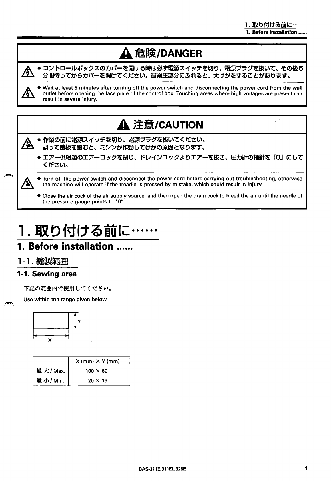
1 -1 .
1-1.
-~ifil!l
Sewing
r~cl7)$EIHJJ*rc:1seffl
Use
within the range given below.
ill
*-!Max.
ft
'J'/
Min.
area
L
"C
X (mm) X Y (mm)
100 X 60
rurc:::
<
t!.
~
"'o
20 X 13
· · · · · ·
BAS-311E,311EL,326E
1
Page 3
1 .
IUl
0 Ml:t
i>
iUIC: · ··
1.
Before installation ..•...
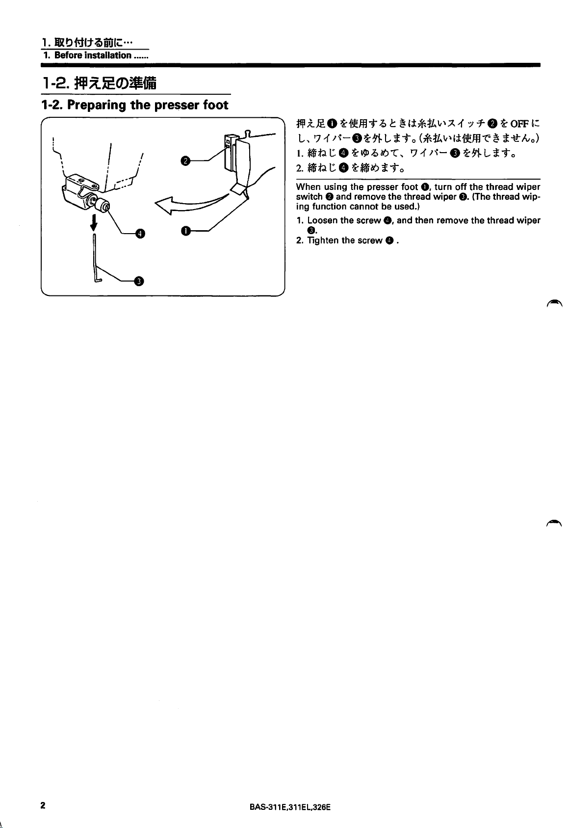
1-2. Preparing
the
presser foot
~;t..@O
L,
t.
*i1ftl
2.
k:mf.l
When using the presser foot
switch 8 and remove the thread wiper
ing function cannot be used.)
1.
Loosen the screw
••
2.
Tighten the screw 8 .
~1~.fflT
71
;'\-
8
t:
8
~~.Q&t)"l,
t:
8
~~~iTo
-0
c
~
';J:*fL\t'.A
~~LiTo
<*1k
71
0,
8,
and then remove the thread wiper
;'\-
turn
"'
8
1 -:17-8
li1~.ffl
~~LiTo
off
the thread
f).
~OFF':
"t"'
~
{The
thread wip-
i-tt
lvo)
wiper
2
BAS-311
E,311 E L,326E
Page 4
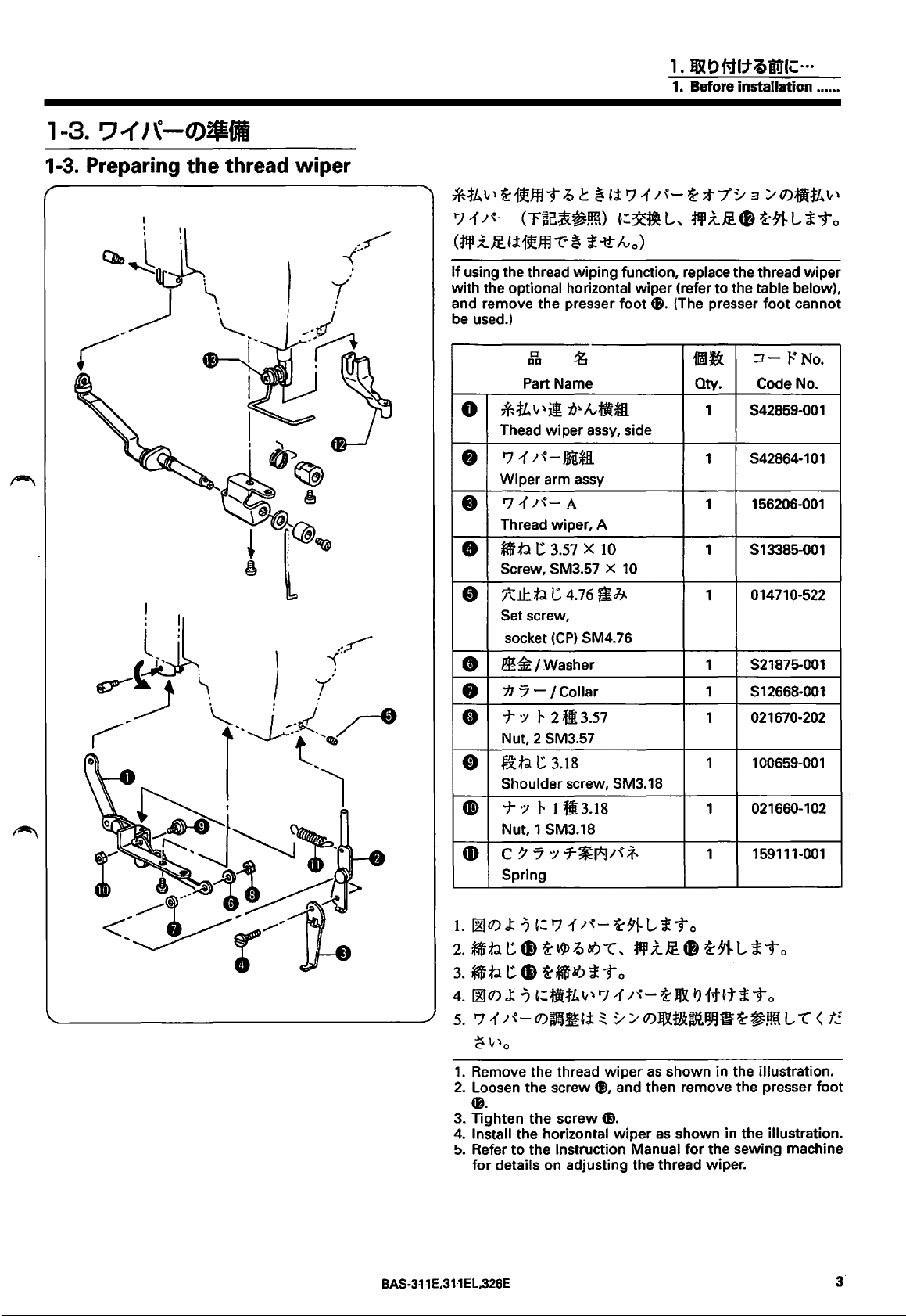
1-3. Preparing the thread wiper
1.
RR~MI:tQiUIC:···
1.
Before installation ..... .
*ikv'
If
with the
and remove the presser
be used.)
a-i5l!ffli"
'71,"-
(liP
.z
.@_
'j:
using the thread wiping function, replace the thread wiper
optional horizontal wiper (refer to the table below),
*iL
0
Thead wiper assy, side
'711'\-JDQU
•
Wiper arm assy
'711'\-
•
Thread wiper, A
f$b
•
Screw, SM3.57 X
J':.IJ:b t 4.76
•
Set screw,
socket
~ c ~
{;t
'711'\-
(rac~~ml)
i5l!ffl""E
Part Name
c
I:U:I
v
'j!!
~
7}~
A
t 3.57 X
':~ilL,
*
-tt
lv
foot
tr
lvftt*li
10
10
0)
tB.
f!Jj.
(CP)
SM4.
76
a-
;t7"~
:JfPX..lf.•
(The presser
i!Mic
Oty.
1
S42859-001
S42864-101
1
1
1
S13385-001
1
3 ;.-Q)•tkv'
a-~
LiTo
foot
cannot
::I-
r"'
No.
Code No.
156206-001
014710-522
https://manualmachine.com/Washer
•
7J
•
0
•
•
•
1.
~Q)
2. $:t.l
3.
$:t.l t 8
4.
5.
1.
Remove the thread
2.
Loosen the screw
••
3. Tighten the screw
4.
Install the horizontal
5.
Refer to the Instruction Manual
for
7 - I Collar
-t
·:;
r
2ft3.57
Nut, 2 SM3.57
~b
t:.
3.18
Shoulder screw, SM3.18
-t
·:;
r
tll3.ts
Nut, 1 SM3.18
c 7 7
Spring
~Q)J:?
'711'\-Q)W!)~{;t
~
\,\0
details on adjusting the thread wiper.
':1
7-~I*J;~
J:
?
':
'711'\-
t:.
8
a-~~&?
a-~&?£
~:ffi'ttLvl'J-{;'\-a-J&JJft'tiTo
;f.
a-~
L £ i" o
-c,
liP
i.l!
i" o
~ ~ ;.tQ)J&fB£~1!JH!t=a-~Jm
wiper
as
CJ),
and then remove the presser foot
ti.
wiper
S21875-001
1
1
S12668-001
1 021670-202
100659-001
1
021660-102
1
1
159111-001
.-
a-;rt.
L t i" o
L
-c
shown in the illustration.
as
shown in the illustration.
for
the sewing machine
<
t!.
BAS-311
E,311
EL,326E
Page 5
1. IUlbiq(:tQil}(\:···
1.
Before installation
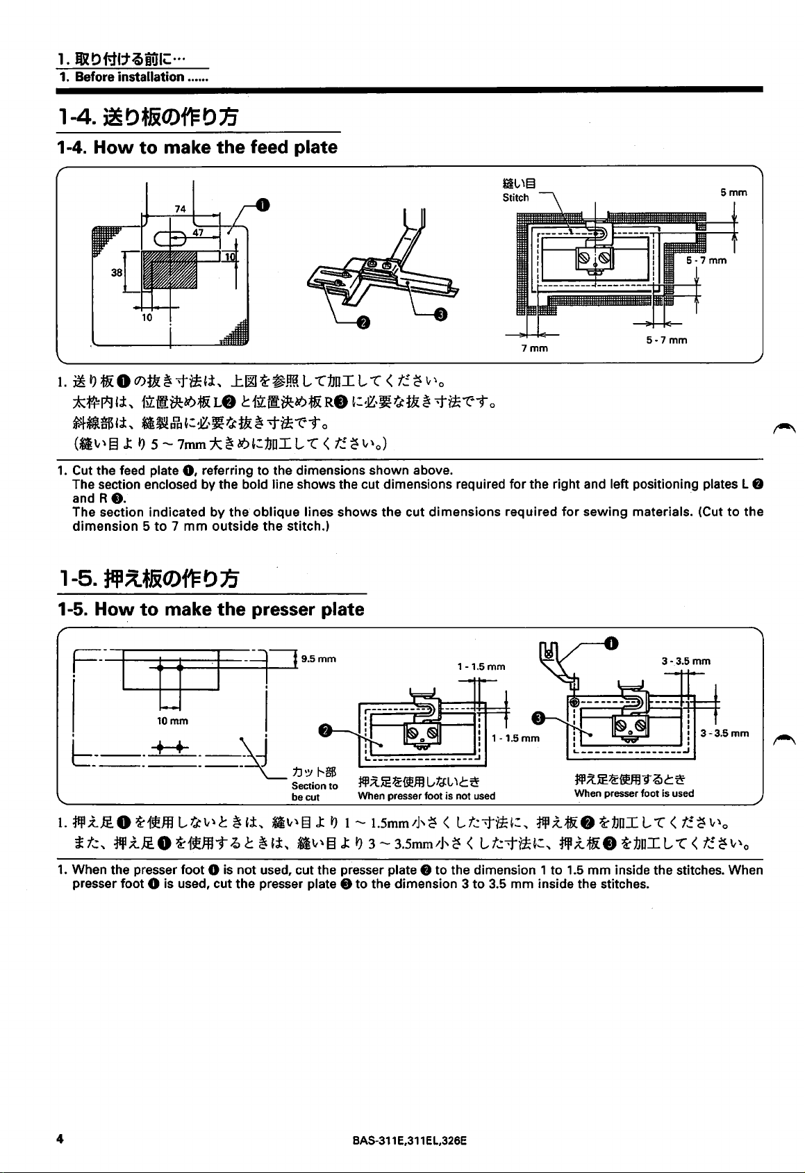
1-4.
How
to make the feed plate
•.•.•.
10
1.
~
l'J
1i 0
O)f!
~
'f~'i,
:i:~I*Hi,
~*lmHi,
(*i"" §
1.
Cut the feed plate
The section enclosed by the bold line shows the cut dimensions required
and R
The section indicated
dimension 5 to 7 mm
flf:tliie&?1&L8 c lli:tl#c&?1&R8
~~Jh~:~-~~t!~
J:
l')
5 -
7mm
0,
8.
J:OO
:k
~
&?
referring
by
the
outside
~~!ffi
L
L"1JDI
L
-c
<
t!.
~:~-~~{!~
-ti*-r'-9 o
':1Jni L
to
oblique
the
-c
<
t!.
~
""o)
the dimensions shown above.
lines shows
stitch.)
the
~
'-'"o
-t~"t"T
cut
dimensions
Jil.,)§
Stitch
7mm
o
for
the right and left positioning plates L 8
required
for
sewing
5-7mm
materials. (Cut
Smm
to
the
1-5. How to make the presser plate
F-1----+--
b---++
----
1.
~X.JE.
£ t.:,
~
1.
When the presser foot 0 is
presser foot
g-+------1
10mm
__
----~
0
~151!ffl
X.JE.
L ~ ""
0
~151!fflT
-~~·:--J
9.5mm
\Jd'
1J'Y
1---$
Section
to
be cut
c
~
,i,
*~""
13
J:
l'J
1 -
o c
~
,i,
*~""
§
J:
l'J
not
used, cut the presser plate 8 to the dimension 1 to
0 is used, cut the presser plate 8 to the dimension 3
1-1.5
¥J!;UE~ffm
When presser foot is
1.5mm
3-
1],
3.5mm
Gta:L-
'c~
~
< L
1]'
~
not
mm
1------fl-:--"~--t
,
___
L
----------------...1
¥JI;{JE~d"Y"
used
t.:-t~':,
< L t.:-ti*,:,
to
3.5
mm
When presser
~X.1i 8 ~1JDI
~X.1& 8 ~1JDI
1.5
mm
inside the stitches.
I
:
.Q
c
is used
-c
L
~
<
"'C
t!.
I
1
:
<
~
3-3.5mm
""o
t!.
~
""o
__;;,;;
___
foot
L
inside the stitches. When
4
BAS-311
E,311
El,326E
Page 6

2.
&t)MI:tn
2.
INSTALLATION
2.
2-1 .
Q)l
b f'i(jJJ' /INSTALLATION
:tEll;{.
rJ9m
/Presser unit
-
...............
__
I.
1fiJ
.Z
JE
1fiJ
.Z
1&: 0 'd:'
I&
tJ
91-
L
't"
,
1fiJ
.Z
JE
8 (
1fiJ
J&tJ91-LiTo
2. *
t)
1&:8
'd:'
1&
t)
91-
L 't",
1JDI
L
t:.~
t)
1&:'d:'
1&
To
1.
Remove the guide plates
foot 8 together
2.
Replace the feed plate 8
made in accordance with
3.
1fii.Z1&:0
4.
91-1fll
.ZJE8 c
.z
JE
1fiJ
.z
1&:
3.
Attach the presser plate 0 to the presser plate holder
4.
Attach the working
sembly
nents
8
with
with
'd:-1f1J.Z;f&*Jv¥-
1fiJ
~
0 t:
1&
to
the presser
guide plates
0,
the work clamp
7 7
t)
foot
and detach the
with
"How
8
:;,.-
7
LA*-0.0
1t
't
i
.,_
8 and the presser crank LA as-
ar'm
0.
8.
the
feed plate
to
make the feed plate."
~:~&
t)
1t£ti't
'd:'*'
X.Ja8
0
C!),
and fix these ·compo-
.·
work
X.
8)
t)
#£t
clamp
that
o
~:,
'd:'
i
was
1fiJ
8.
--
..
:~
5.
1)l:f1~&?1&:R0
c
1)l:i1~&?1&:L4D
~91-~X.JE&~:l&
1ttt£To
5.
Attach the positioning plate R «!)and the positioning plate
L
tJ)
to
the working
foot
8.
t)
BAS-3 1 1
E,3
1 1 E
L,326E
5
Page 7

2. llit>MI:tn
2.
INSTALLATION
2-2.
IJ7-IJ9ii
2-2. Pneumatic system
1.
.r{Jv
r
7J
;'\-
0,
1ftUiii7J
(
~
~
:/
(J)JD(tj~PJH~F~fflO
1.
Remove the belt cover 0 and the side cover
(Refer to the Instruction Manual for the sewing machine.)
;'\-
8
~1&
t'J
~Li-to
8.
2.
:I*'7·?
3.1[S;'\Jv/f),
4 .
.OC~JfJ
JDl.
s .
.OC~JfJl[ift;'\Jv/*-0.
2.
Push
3.
Remove the solenoid valve 8 and
4.
Install the solenoid valve 8 and
valve assembly
5.
Install the reversal solenoid valve assembly 0 to the leg.
80)@$~~L
l[ift;'\
t'J
#~ti
To
down the
8,
Jv
/*-D.
part®
0.
r~f,
:I*'7?8,
0
~:JD(
t')
0
~
JJI4I
':JD(
of
the connector
:r..7-7-:1.-7·
1:/'T~v-?8,
~Lt.:
t?ta;'\
t'J
1-J·'t i "to
8,
8,
the connectors
8,
the connectors
Jv
/8,
and pull out the air tubes
(4*)
8,
8
~51~!!~
.:r..7--:<77-8~l&t'J~Li"to
(t,
:I
*' 7 ?
8,
the integrator 8 and the air muffler
the integrator 8 and the air muffler 8 to the reversal solenoid
8,
(4
iTo
1
pes)
:/
7
8.
~
v-
?
8,
8.
.:r..
7
--:<
7
7-
8
~
6
BAS-311 E,311EL,326E
Page 8

~
6.
::1;;
r
o-
7.
J~Jv:fJ\-
s.
.OC~Jfl
:fb:#
tift;~
iTo
Jv~
'J 7 .A(J)jf
*'.A
(12P)
Jv
:141)
(~lil&1tli)
CD>~~~
(J) ~ ;;
? -
iTo
~
"T
Jv
(
ttilt
~
IJJHti
1::.-:'
;;
To
(
,
41ft: ~ ;; )
~
~;,.,
(J)J&fll~I~Jl&$Jm)
~;
~
Jv
:1;
\-
*'
.A
8
(J)
::1
*'
2.
IIROMI:t1J
2. INSTALLATION
7 ? ttl=..
41=
~:
£
L.
6.
Open the control box cover (circuit board installation plate). (Refer
7. Disconnect the
8.
Insert the pin terminals
2-a.
2-3.
~m
Piping
valve harness
(#11,
(12P)
Cl>.
#4)
of
the reversal solenoid valve
to
the Instruction Manual
tD
into connectors
for
the sewing machine.)
#11
and #4 on the valve harness
Cl>.
1.
Connect each air tube
to
the locations with identical numbers.
BAS-311
E,311 E L,326E
7
Page 9

2.
u
t>
i'il:tn
2.
INSTALLATION
1
2 .
.&!Iii~
3.
""'Jv
2.
Bind the air tubes from the reversal cylinder with a spiral tube.
3.
Install the belt cover 0 and the side cover
) "'./
~-(J):r_
~
7.7
;'\-
o
..
ili~W
71-
:J..-7·"1i:
7.7
;'\-
8
Al'L{
"li:
~
7'Jv1-
tJ
1t~t
f).
.:r..
-7"1:'*tJ
~-to < ~
(Refer
~ / (J)~t.&~sti!IH!t=~Jm)
to
the Instruction Manual
~-to
for
the sewing machine.)
2-4. 7-'(
2-4. DIP
switch
':1
-:17..-1
':1
70)tJJ
selection
bli;{.
(C::j:£10
71
·:;"'/A 1
<
f!.
~
v"o
1.
71
·:;
L~To
*
.&!lii~tl
No.3 t No.6
[Caution]
Be
sure to turn
DIP
switch settings.
1.
Turn the selectors No.3, No.4 and No.6 on the
@to
"ON".
* When the reversal crank device is
selectors No.3 and No.6 on the
"'/;A
·:;
7-(J)~J!(J)~~:
1
·:;
7-@
(J)
No.3, No.4 t
"li:15f!ffl
L
1j:
""
"li:
"OFF"
off
the power before changing any
'
t
~
~:
,i,
,i,
71
L "( <
DIP
1l--r~ili.~ID
t!.
not
'?
"(
No.6~
~
switch to "OFF".
"ON".':
7 "'/A 1
':J
v"o
of
DIP
switch
used, turn the
1-(J)
the
~
8
BAS-311
E,311 E L,326E
Page 10

3.~~
3.
ADJUSTMENT
3.~~
3.
ADJUSTMENT
3-1 .
g;g~J±O)~~
3-1. Adjustment of air pressure
I.
~Jn.EE
<~~JJ)~)
'j:, 0.49MPa (
1
/77·v-~
Q
5kgf
O)J\/
2
/cm
-r-f~ffll
)
r·Jvf)~51~
';t
To
..
tJfl"il't?
!Hill"{Tlj:v'';tTo
w.l~f.fTi~'i,J\/
!-"Jvf)~r""'-:ttfll-co-;;7l;t
T o
2.
JX!Piffl
x.
t::.
:,-
e:
~ ~=,
'J
:;..-
1'0)~3n_EE,i,
~P
x.
7 7
:;..-
7
o
:flll
.:t.W:O-r-~~!}o/.1
n~
&!Pi-t
.Q
!lm!W
~:flll
~
1*1
~=
l
;t
T o
<~~JJ)~)
:r..
7-
v.::r;J.
v-
~
0
0);\
:;..-
r·
Jv
0
~51
~..tffl"
il'
t?
@J
ll"{Tv,
fful~*~
T1~'j:;
;t
\
/
-t
o
r:·
Jv
0
~
r
""-:fill
L
-co
-;;
7 L ;t
To
3. 1
:;..-
-r
7·
v-
~
0
0)
*.
r
;~-ti*J
~=71<1.1{t::_
1/~-;;7Q~~~O)~~~@ll"7J<~~~';tT
1.
Air
pressure should
The
air
pressure can
ing
the co
ntr
ol knob
After adjustment is complete, push the
downw
2. Adjust the
within such a
versely wh
su
For adjustment, pull up and,
the
Aft
to
3.
If
drain cock
drain the water.
ard
to
air
en
re plate
air
er adjustment is complete, push the handle 0
lock it.
wat
er stands in the
pressing the sewing material
0.
regulator
f)
be
0.49 MPa [5 kg/cm
be
adjusted by pulling up and turn-
f)
on the
lock it.
pressure
ra
nge that the presser crank G rotates re-
0.
in the direc
for
bott
integrat
the reversal cyli
turn
the control knob 0 on
le of the integrator 0 ,
tion
indicated
;t ·:d.:: t?,
2
).
or
0.
contro
nder
wit
by
an a
r·
v
o
l knob
f)
to
stay
h the pres-
down
turn
the
rrow
to
BA
S-311 E,311EL,326E 9
Page 11

3.~~
3. ADJUS
TMENT
3-2. Adjustment of
3-3. Adjustment of
the
positioning plates
1.
*'lv'EI
~l~~.-~c8~~~~-z:-~
L,
iT
it.:,
~
C 8
1.
Loosen the screws
sitioning
out
betw
Nex
t, loosen the screws
positioning
evenly laid o
the
presser crank horizontal position
<fiJI
;t?
5:;?
1
JX~i
~
~~.
When
Loosen the nut 0 and push in or pull o
0 so
reversal cy linder pl
)
~
'
:jifl
;Z
#Jv
the
that
(A)
7'P7~J
v01
:Ml"Z:"IVri~:1JioJi1t:!S)~I:~
•~
~•R•~••
o
:tc:ti:1JioJii*1
~ ~ ~ ~ "Z:"
plate R
een the
plate L 0 so
ut
tJ
/ .y
{/)
7 7 / 7 8
~ G~l±ll.Ahl"Z:"RJlliTo
presser
the presser crank
v'EI
(
f
}[:Ji;'R:~
f),
and adjust the
f)
so
that
the label 0 can be evenly la
front
and back seams (A).
8,
that
between the le
':EifflU(J)
-j'
7 /
-/.){7](
crank
unger
t:
:;
.if 1:
is
0 is
~
-\'
in
f)
>
0
B)
iJf:lSJ~I:~~
-
L0
~--l
position
and adjust the posi
the presse r plate can be
ft
and
right
~
:ti""'"'
~
~ l ~
1:'
the
right
position
ed
ut
hor
to th
can be
mov
l
seams
-?
I
fit'
-j-
·:;
the a
djusting bolt
izontal
e ri
ght
~
iT
of
tion
l±l
~ 8 ~
when
extreme.
1:,.
o
the
of the
(B)
L,
t.:
po-
id
.
C:
~
the
tJta:l'le(
D
DO
~
R/ W
BA
0
~~
0~
:>.~-·
05PEEQ
0
IAtJ?
B.T.
COUNTER
0
:>.7'•J·~~N
SPUT NO.
D
S-3
:~=...,
:.-9-
00E
r!tNU
I
O.
series
un
l
@~
(
til~)
I.
77.
~
.
il
0
POWE
R
;fffi
*
2.
:Jifi;Z
*:Jifl
3.
-T.A
Verification
1.
Whil
sw
*
2. Tread th e presser li
* Make s
3.
Press th e test switch again to e
7.1·:;-T0~
liT
o
3!Vf-i1'
_Uf~.YJ
:Jifl
X..
(
7 8
X..
~
-?
~.A1
e press
itch
Th
e indi
Verify th
(
tr
od, the presser cran k
pr
esser plate 0 and the pos
( C
_t
1 f
~
.Y
il{:tc:ti
7 7 / 7 8
"("
"'
~
v'
>'T0~
ing the test swit
0.
cator shows
at
whenever
ure th
:Jifl
l.,~i1{t.>~/m:.A
,:;
)
C: ~ iJ iTo
v f)
~lf6}j.i-f
Jv
8
~
1:
JX~i
~
-1.1''.
:Jifl
il'lii
-/.)
>
~
:Jifl
-tC:Ml~~hiT
lf6
tr
<
iJ
~ l
X...
"("
< t
ch
.::
o
C:
9
:.
0,
C ~ .
fte
r pedal 8 .
the
presser
f)
flip
s le
at the presser crank
itioning
nd the test
1·:;-T0
1: , :Jifl
~
;Z
7 7 / )
i-t
o
C:
f}[:R
;'R:~-
"'
0
press the read/write
lift
er pedal 8 is
ft
or right.
f)
does
plate R
o
not
mod
R0
hit the
0.
e.
~
1:
10
BAS-311 E,3
11
E L,326E
Page 12

3-4. Adjustment of the presser plate lifting speed
t.
~tmr\Jv 7 0)~~~~
t:.
8
a-lill
...tfHUO)n~1n:*f
0)~~~*!
•
tm;~
• iftiQ;
1.
Loosen the nut 0 on the exhaust air throttle valve
Slower
the solenoid valve, and turn the adjusting screw 8
adjust the presser plate lifting speed.
The upper exhaust air throttle valve adjusts the presser
plate ascending speed,
throttle valve adjusts the descending speed.
· Solenoid valve
· Solenoid valve ®
3.1111
3. ADJUSTMENT
t'J
1f0)
7-
7 r 0
L
"t"ftv~
t'J
#'±:f11J..t7.1{r7.1{~
Jv
7
~
Jv
7·
iTo
t'J
#tt:f11J..t
7.1f...t7.1f.Q
c
Q}·····:f111
®· · ··
..ttim
·
·1ll:tl~~tim
while
<D
••••••
for
the presser plate
......
for
the positioning plates
a-~
c
~
0)~
~
O))l~
the
lower
.Q
~,
im.Jftil
~a-,
'l:~~
LiTo
exhaust
h
r·nm
for
to
air
'
BAS-311
E,311
EL,326E
,.,
Page 13

4.11!1
4.
·NOTES
TO
SEWING
OPERATIONS
4. NOTES TO SEWING OPERATIONS
1.
~
Lllv'Q)~IHHi,
Reference point
1.
Reverse stitching is possible within 4.5
from the reference point.
*lv'MlN'JQ)£~.~J:
mm
l'J
ti:;f:i~:
left and right
:{pO)J!jl(b
Thickness
of
material
ll~~tJ{fJv'jj.g.,
2.
oc~T
.Q
c
~, ~tc
~~+
~:;iHj§£,~
t.:.
t!.
L,
:i!!)!!t~tJ{ft~jt
~
1~Q)jf*'1.J{~·~W.J:J:~
-Jil/J,ffi!M~:
(~$Q)jf*'~~
2.
For thick materials, provide a shunting point at the last
needle position in the program to prevent the presser
crank
pleted.
If
the shunting point is
tion, the needle thread after thread trimming may be too
long.
tance from the last stitch position.
~~
0 from striking the needle after sewing is com-
Set the shunting point at the shortest possible dis-
ilv'~t> ~ 1~~:;f1JJ
~t.:.
~
~"'
J:-?
~::to
a-~~t""C
L
""C
,i,
(
f!.
~
v'o
J:
l'J
~tt~
<
~
<
t!.
~
v'o
35-
40mm
too
far from the last stitch posi-
.Q.::
"t"'T
c
~·""C
.:t
7 7 ~ 7
~7 A Q)~
"'
.Q
tJ{~
tJ
"£
o)
c,
TQ)'t",
OiJ{
r-'\
*W
12
BAS-311E,311EL,326E
Page 14

••
••
77t:t-J:IIfli"tGf.l:
um~B.ijlf
INSTRUCTION MANUAL
BROTHER
=f467-8562
Printed
INDUSTRIES,L
~i!imiflliMii~}D.J~-
in
Japan
TO.
NAGOYA,JAPAN
TEll
Ill~
TEL(052)824-2392
151-Vll,V12,V26
S93Vll-221
1999.03
BCD
 Loading...