

Page 1

SERVICE MANUAL
BAS-311E,311EL
BAS-326E,326EL
Please read this manual before making any adjustments.
PROGRAMMABLE ELECTRONIC PATTERN SEWER
WITH CYLINDER BED
Page 2
This service manual is intended for BAS-311E, 311EL and 326E; be sure to read the BAS-311E, 311EL,
and 326E, 326EL instruction manuals before this manual.
Carefully read the “SAFETY INSTRUCTIONS” below and the whole of this manual to understand this
product before you start maintenance.
As a result of research and improvements regarding this product, some details of this manual may not be
the same as those for the product you purchased.
If you have any questions regarding this product, please contact a Brother dealer.
SAFETY INSTRUCTIONS
z Safety indications and their meanings
This instruction manual and the indications and symbols that are used on the machine itself are provided in
order to ensure safe operation of this machine and to prevent accidents and injury to yourself or other
people. The meanings of these indications and symbols are given below.
Indications
DANGER
CAUTION
Symbols
.................This symbol ( ) indicates something that you should be careful of. The picture
.................This symbol (
.................This symbol (
The instructions which follow this term indicate situations where failure to
follow the instructions will almost certainly result in death or severe injury.
The instructions which follow this term indicate situations where failure to
follow the instructions could cause injury when using the machine or physical
damage to equipment and surroundings.
inside the triangle indicates the nature of the caution that must be taken.
(For example, the symbol at left means "beware of injury".)
) indicates something that you must not do.
) indicates something that you must do. The picture inside the
circle indicates the nature of the thing that must be done.
(For example, the symbol at left means "you must make the ground connection".)
BAS-311E.311EL.326E.326EL
i
Page 3
x Notes on safety
Wait at least 5 minutes after turning off the power switch and disconnecting the power cord from
the wall outlet before opening the face plate of the control box.
Touching areas where high voltages are present can result in severe injury.
DANGER
CAUTION
Installation
Machine installation should only be carried
out by a qualified technician.
Contact your Brother dealer or a qualified
electrician for any electrical work that may
need to be done.
The sewing machine weights more than
BAS-311E60kg,BAS-311EL·326E·
326EL65kg. The installation should be carried out by two or more people.
Do not connect the power cord until installation is complete, otherwise the machine
may operate if the start switch is pressed
by mistake, which could result in injury.
Be sure to connect the ground. If the ground
connection is not secure, you run a high risk
of receiving a serious electric shock, and
problems with correct operation may also
occur.
Sewing
Be sure to wear protective goggles and
gloves when handling the lubricating oil and
grease, so that they do not get into your eyes
or onto your skin, otherwise inflammation can
result.
Furthermore, do not drink the oil or eat the
grease under any circumstances, as they can
cause vomiting and diarrhoea.
Keep the oil out of the reach of children.
Avoid setting up the sewing machine near
sources of strong electrical noise such as
high-frequency welding equipment.
If this precaution is not taken, incorrect machine operation may re
Have two people present to hold the machine
head with both their hands when tilting it back
or returning it to its original position.
This sewing machine should only be used
by operators who have received the
neccessary training in safe use beforehand.
The sewing machine should not be used
for any applications other than sewing.
Attach all safety devices before using the
sewing machine.
If the machine is used without these devices
attached, injury may result.
Turn off the power switch at the following
times, otherwise the machine may operate
if the start switch is pressed by mistake,
which could result in injury.
• When not using the machine
• When leaving the machine unattended
ii
BAS-311E.311EL.326E.326EL
Do not touch any of the moving parts or press
any objects against the machine while sewing, as this may result in personal injury or
damage to the machine.
If an error occurs in machine operation, or if
abnormal noises or smells are noticed, immediately turn off the power switch. Then
contact your nearese Brother dealer or a
qualified technician.
If the machine develops a problem, contact
your nearest Brother dealer or a qualified
technician.
If using a work table which has casters, the
casters chould be secured in such a way so
that they cannot move.
Page 4
CAUTION
Cleaning
Turn off the power switch before starting any
cleaning work, otherwise the machine may
operate if the start switch is pressed by mistake, which could result in injury.
Maintenance and inspection
Maintenance and inspection of the sewing
machine should only be carried out by a
qualified technician.
Ask your Brother dealer or a qualified electrician to carry out any maintenance and
inspection of the electrical system.
Turn off the power switch and disconnect
the power cord from the wall outlet at the
following times, otherwise the machine may
operate if the start switch is pressed by mistake, which could result in injury.
• When carrying out inspection, adjustment
and maintenance
• When replacing consumable parts such
as the rotary hook and knife
Disconnect the air hoses from the air supply and wait for the needle on the pressure
gauge to drop to "0" before carrying out inspection, adjustment and repair of any parts
which use the pneumatic equipment.
Be sure to wear protective goggles and
gloves when handling the lubricating oil and
grease, so that they do not get into your eyes
or onto your skin otherwise inflammation can
result.
Furthermore, do not drink the oil or eat the
grease under any circumstances, as they can
cause vomiting and diarrhoea.
Keep the oil out of the reach of children.
If the power switch and air need to be left on
when carrying out some adjustment, be extremely careful to observe all safety precautions.
Use only the proper replacement parts as
specified by Brother.
If any safety devices have been removed, be
absolutely sure to re-install them to their original positions and check that they operate
correctly before using the machine.
Any problems in machine operation which
result from unauthorized modifications to the
machine will not be covered by the warranty.
Have two people present to hold the machine
head with both their hands when tilting it back
or returning it to its original position.
BAS-311E.311EL.326E.326EL
iii
Page 5
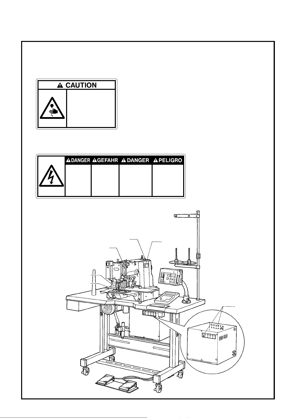
c Warning labels
★The following warning labels appear on the sewing machine.
Please follow the instructions on the labels at all times when using the machine. If the labels have
been removed or are difficult to read, please contact your nearest Brother dealer.
1
Moving parts
may cause injury.
Operate with safety de vices .
Turn off main switch before
threading, changing bobbin
and needle, cleaning etc.
Safety devices: Thread take-up cover,
Eye guard, Belt cover,
Finger guard, etc.
2
Hazardous voltage
will cause injury.
Turn off main
switch and wait 5
minutes before
opening this cover.
Hochspannung
verletzungsgefahr!
Bitte schalten sie den
hauptschalter aus und
warten sie 5 minuten,
bevor sie diese
abdeckung öffnen.
Un voltage non adapté
provoque des blessures.
Eteindrel'interrupteur et
attendre 5 minutes
avantd' ouvrir le capot
Un voltaje inadecuado
puede provocar las
heridas.
Apagar el interruptor
principal y esperar 5
minutos antes de abrir
esta cubierta.
[BAS-311E]
Eye guard
Finger guard
Belt cover
Thread take-up
cover
1
1
2
iv
BAS-311E.311EL.326E.326EL
Page 6

Explanation of models
This manual explains three models
•BAS-311E (Solenoid type, Pnevmatic type), 311EL (Pnevmatic type), 326E, 326EL
(Pnevmatic type)
Explanation for individual model is provided by identifying the model name. Check the
model before useing the machine.
INDEX
Chapter 1. Mechanical description ........................................................... 1
1. Needle bar, thread take-up, lower shaft and shuttle hook mechanism................. 1
2. Work clamp lifting mechanism (1)(2) ....................................................................... 2
3. Feed mechanism (X axis) .......................................................................................... 4
4. Presser foot mechanism (1)(2) .................................................................................. 6
5. Thread trimmer mechanism ..................................................................................... 8
6. Thread nipper (1)(2) when presser foot rises ......................................................... 9
7. Thread wiper (1) (2).................................................................................................... 10
Chapter 2. Disassembly ............................................................................. 11
1. Covers (1)(2)(3) ........................................................................................................... 11
2. Feed mechanism ........................................................................................................ 13
3. Presser foot mechanism ............................................................................................ 14
4. Needle bar mechanism.............................................................................................. 15
5. Upper shaft mechanism ............................................................................................ 16
6. Feed mechanism (Y axis)(1)(2)(3) ............................................................................. 17
7. Feed mechanism (X axis)(1)(2) ................................................................................. 20
8. Lower shaft mechanism ............................................................................................ 22
9. Work clamp lifter (Solenoid type) ............................................................................. 23
10. Thread nipper mechanism ........................................................................................ 24
11. Thread trimmer mechanism .................................................................................... 25
Chapter 3. Assembly .................................................................................. 26
1. Thread trimmer mechanism (1) ................................................................................ 26
2. Thread nipper mechanism ........................................................................................ 27
BAS-311E.311EL.326E.326EL
Page 7

3. Work clamp lifter mechanism .................................................................................. 29
4. Feed mechanism (X axis) .......................................................................................... 31
5. Feed mechanism (Y axis) .......................................................................................... 35
6. Upper shaft mechanism ............................................................................................ 39
7. Needle bar mechanism.............................................................................................. 40
8. Presser foot mechanism ............................................................................................ 41
9. Lower shaft mechanism (1) ....................................................................................... 43
10. Lower shaft (Rotary hook) (2).................................................................................... 44
11. Thread trimmer mechanism ..................................................................................... 45
12. Feed guide mechanism (Home position adjustment: X ) ....................................... 46
13. Covers ......................................................................................................................... 49
Chapter 4. Adjustments ............................................................................. 51
1. Adjusting the needle bar height adjustment ........................................................... 51
2. Adjusting the needle bar lift amount........................................................................ 51
3. Adjusting the needle clearance................................................................................. 52
4. Adjusting the driver needle guard ............................................................................ 52
5. Adjusting the shuttle race thread guide ................................................................... 52
6. Adjusting the two-step work clamp lift amount ...................................................... 53
7. Adjusting the movable knife ..................................................................................... 55
8. Adjusting the lowest point of the presser foot ........................................................ 58
9. Changing the presser foot lift ................................................................................... 59
10. Wiper adjustment....................................................................................................... 60
11. Adjusting the home position..................................................................................... 61
12. Adjusting the tension of the timing belt .................................................................. 64
13. Adjusting backlashes ................................................................................................. 66
14. Adjusting the driving lever stopper position ........................................................... 67
15. Adjusting the thread trimmer driving lever position .............................................. 67
16. Work clamp lift components for manual operation (Solenoid type) ..................... 68
17. Adjusting the presser foot height ............................................................................. 68
18. Adjusting the needle up step position ..................................................................... 69
BAS-311E.311EL.326E.326EL
Page 8

Chapter 5. How to make up the work clamp........................................... 70
1. How to make up clamping type work clamp ........................................................... 70
2. How to make up cassette type work clamp ............................................................. 71
Chapter 6. Power supply and electrical parts adjustment ..................... 73
1. Precautions at the time of adjustment ..................................................................... 73
2. Components inside the control box ......................................................................... 73
3. Fuse explanation ........................................................................................................ 74
4. Connectors.................................................................................................................. 75
5. DIP switches ............................................................................................................... 82
6. Changing special functions using the memory switches ....................................... 86
7. Checking the input sensor and DIP switch input ..................................................... 90
8. Checking the input voltage........................................................................................ 91
9. Clearing all memory settings .................................................................................... 91
10. Confirming software version .................................................................................... 92
11. Error codes ................................................................................................................. 93
Chapter 7. Trouble shooting ..................................................................... 95
Flowchart .................................................................................................................... 95
Problem solution and measures ............................................................................... 101
Chapter 8. 1. Gauge parts list according to subclasses .......................... 112
Chapter 9. Gauge parts list........................................................................ 113
Chapter 10. Option parts ............................................................................. 123
Control Block diagram ............................................................................................... 140
BAS-311E.311EL.326E.326EL
Page 9
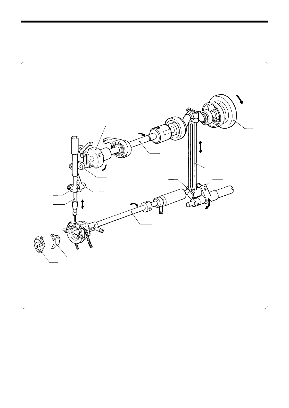
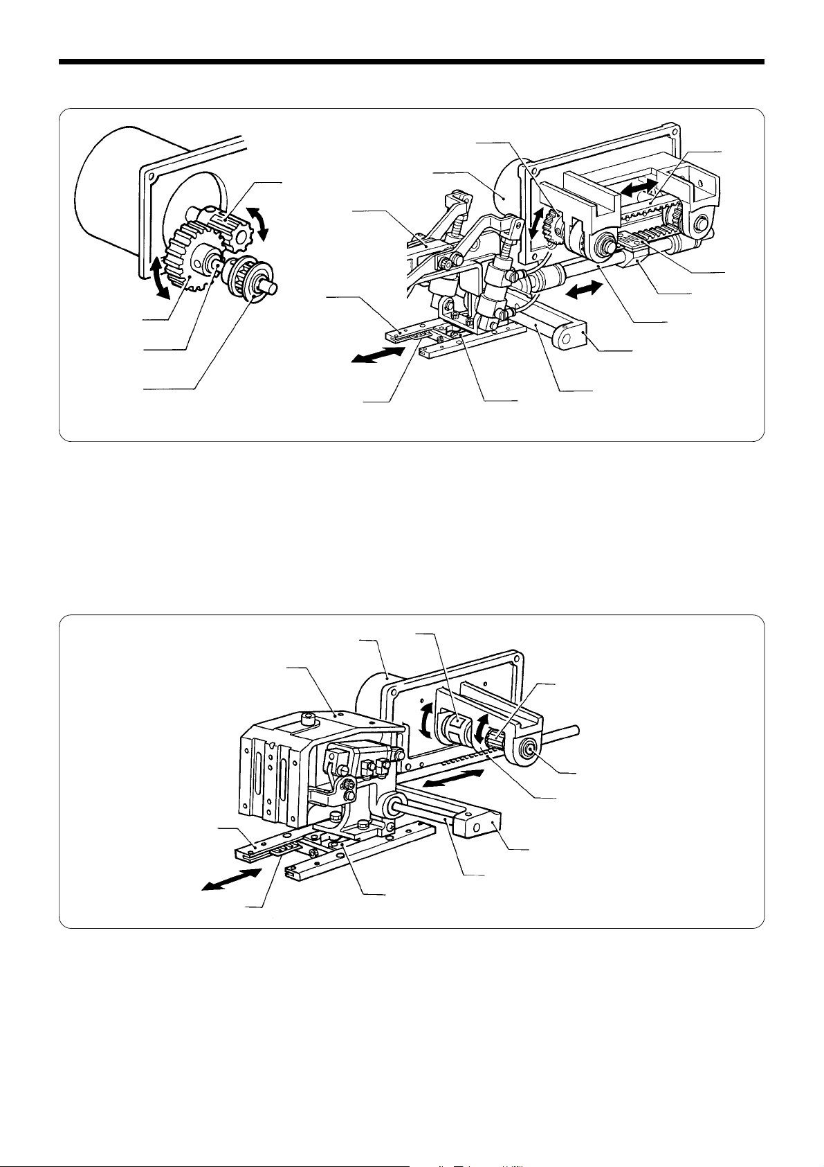
Chapter 1. Mechanical description
Chapter 1. Mechanical description
1. Needle bar, thread take-up, lower shaft and shuttle hook mechanism
y
u
!3
!2
t
r
e
!1
w
!0
q
i
o
1. When the machine pulley q rotates in the direction of the arrow, the upper shaft w rotates, then it rotates the thread
take-up crank e.
2. The needle bar crank r, attached to the thread take-up crank e, moves the thread take-up lever t.
3. The needle bar u attached to the needle bar clamp y is moved up and down.
4. When the machine pulley q rotates in the direction of the arrow, the crank rod i attached to the upper shaft w moves
up and down.
5. The crank rod i oscillates the attached rock gear o.
6. The rock gear o oscillates the lower shaft !1 through the lower shaft gear !0. The lower shaft !1 oscillates the attached
driver !2 and inner rotary hook !3 in the shuttle hook mechanism.
BAS-311E.311EL.326E.326EL
1
Page 10
Chapter 1. Mechanical description
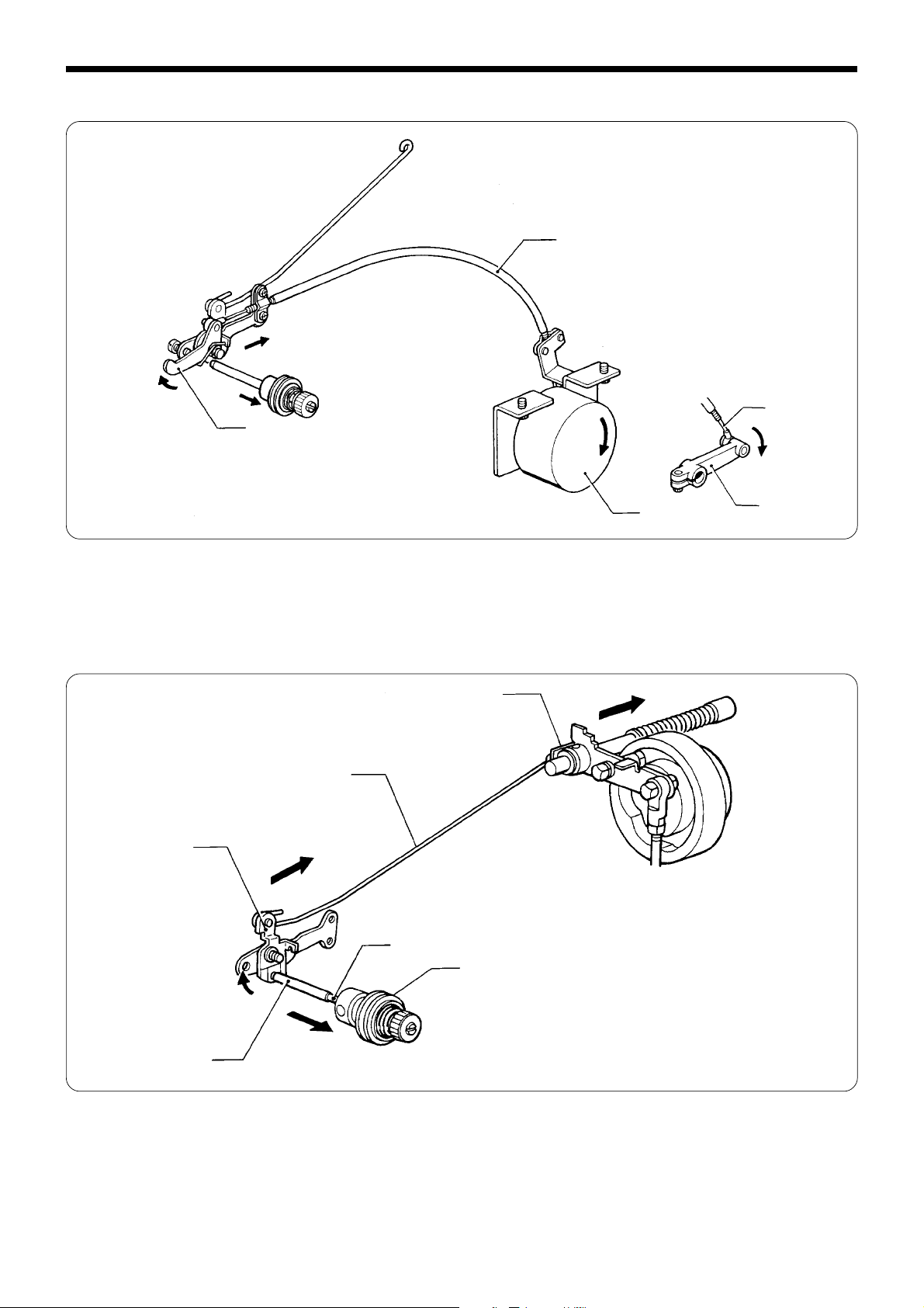
2. Work clamp lifting mechanism (1) (Solenoid type), 311E
e
r
q
w
t
y
u
1. When the presser signal is on, the presser solenoid q operates.
2. The plunger w operates in the direction of the arrow and moves link (B) t through link (C) e and link shaft (A) r.
3. Link (B) t presses down the presser plate u through the link shaft (C) y.
i
!1
o
!6
!0
!2
!3
!4
!5
!7
4. When the work clamp plate operates, the slider i and the slider support o are pressed down. When they are pressed,
work clamp lifter lever R. !1 is raised through the slider support shaft !0.
5. The spring !2, the work clamp arm lever (RR) !3 and (F) !4 which are linked to presser bar lifter lever (R) !1 operate in the
direction of the arrow.
6. Work clamp (UN) !5 and presser foot (L) !6 ·(R) !7 are pressed down through work clamp lever (F) !4.
2
BAS-311E.311EL.326E.326EL
Page 11
Chapter 1. Mechanical description
Work clamp lifting mechanism (2) 311E, 311EL
(Pneumatictype)
e
r
w
q
1. When the air cylinder q operates in the direction of the arrow, work clamp arm levers R w and F e also operate in the
direction of the arrow.
2. Work clamp SE r is moved vertically via work clamp arm lever F e.
Work clamp lifting mechanism 326E
w
e
r
q
1. When the air cylinder q operates in the direction of the arrow, work clamp lifter lever D w and lever U e also operate
in the direction of the arrow.
2. Work clamp SE r is moved vertically via knee lifter lifting lever U e.
BAS-311E.311EL.326E.326EL
3
Page 12
Chapter 1. Mechanical description
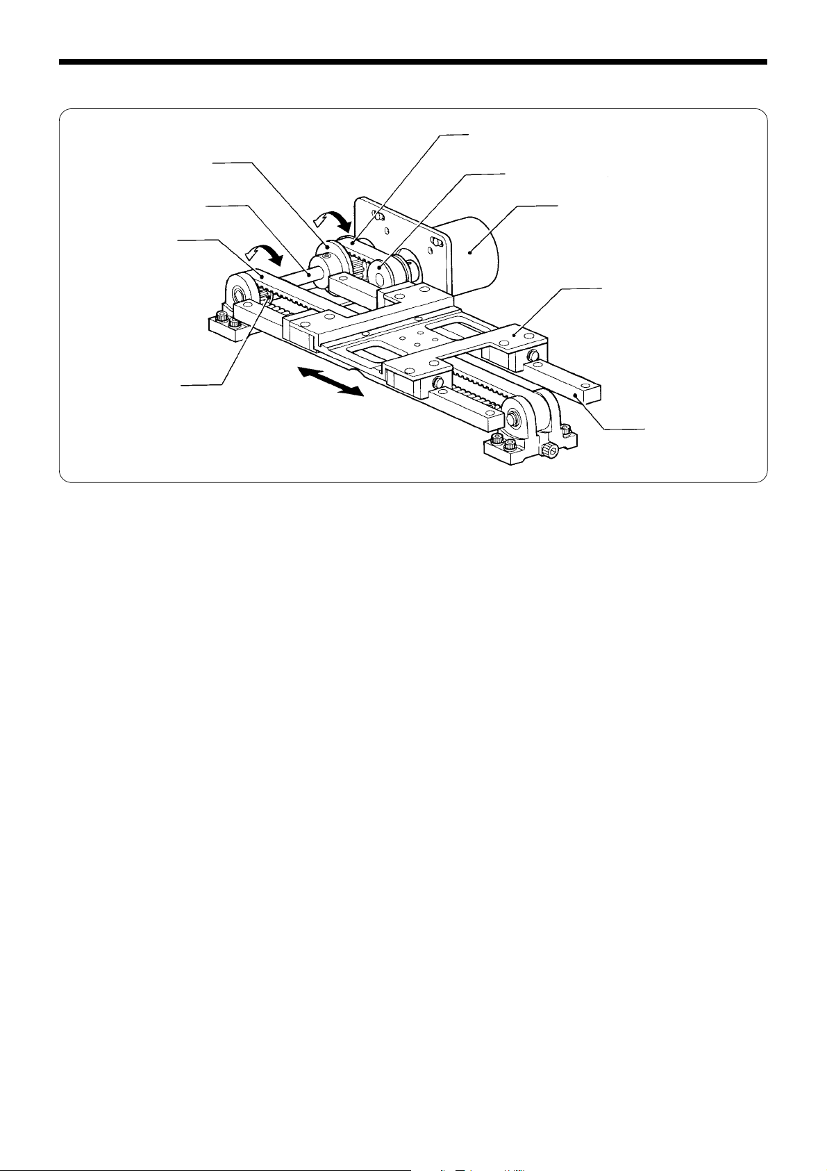
3. Feed mechanism (X axis) 311E, 311EL, 326E, 326EL
e
r
t
u
y
1. When X-timing pulley A326 w attached to the X-pulse motor q moves, its motion is transmitted to X-timing pulley
B311 r via X-timing belt A311 e.
2. When X-timing pulley B311 r moves, timing pulley A y linked to the X-timing pulley shaft t moves X-timing belt
B311 u left and right.
3. Feed bracket X i secured to X-timing belt B311 u moves via linear guide 311 o in the X direction (left and right).
w
q
i
o
4
BAS-311E.311EL.326E.326EL
Page 13
Feed mechanism (Y axis) 311E and 311EL
Chapter 1. Mechanical description
e
w
!2
!5
e
r
t
!4
1. The driving gear w attached to the Y-pulse motor q oscillates the idle gear e.
2. When the idle gear e oscillates, the Y-timing belt y moves forward and backward through timing pulley (A)t attached
to Y-pulley shaft (A)r.
3. The belt holder u and the Y-driving shaft holder i which are fixed to the Y-timing belt y operate the Y-driving shaft o.
4. The X-feed shaft support !0 and the X-feed shaft !1 are attached to the Y-driving shaft o. The presser arm assembly !2
is attached to the Y-feed bracket !3.
5. The Y-feed bracket !3 operates in the Y-direction (moves longitudinally) via the Cross roller !4 and the Y-feed guide !5.
q
!3
o
!0
!1
y
u
i
Feed mechanism (Y axis) 326E, 326EL
q
i
!1
!0
1. When the Y-pulse motor q operates, its motion is transmitted to the driving gear r attached to the Y-driving gear shaft
e via the coupling w.
2. The driving gear r is engaged with the rack of the Y-driving shaft t, and the Y-driving shaft t moves back and forth.
3. The work clamp arm assy i is attached to the Y-feed bracket o via X-feed shaft support 326 y attached to the Y-
driving shaft t and the X-feed shaft u.
4. The Y-feed bracket o operates in the Y-direction (back and forth) via cross roller 326 !0 and Y-feed guide 326Y !1.
w
r
e
t
y
u
o
BAS-311E.311EL.326E.326EL
5
Page 14
Chapter 1. Mechanical description
4. Presser foot mechanism (1)
r
t
y
u
e
q
w
1. When the upper shaft q rotates, the stepping work clamp cam w moves eccentrically, and the stepping work clamp
connecting rod e oscillates stepping work clamp arm R r.
2. The oscillation of stepping work clamp arm R r is transmitted to stepping work clamp arm F t, and the stepping link
assy y moves the presser bar lifter u up and down.
6
BAS-311E.311EL.326E.326EL
Page 15
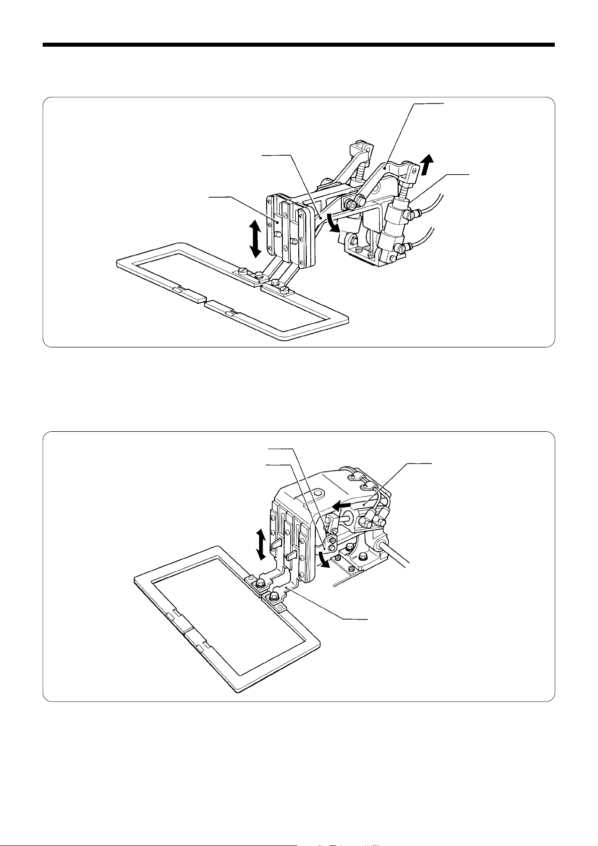
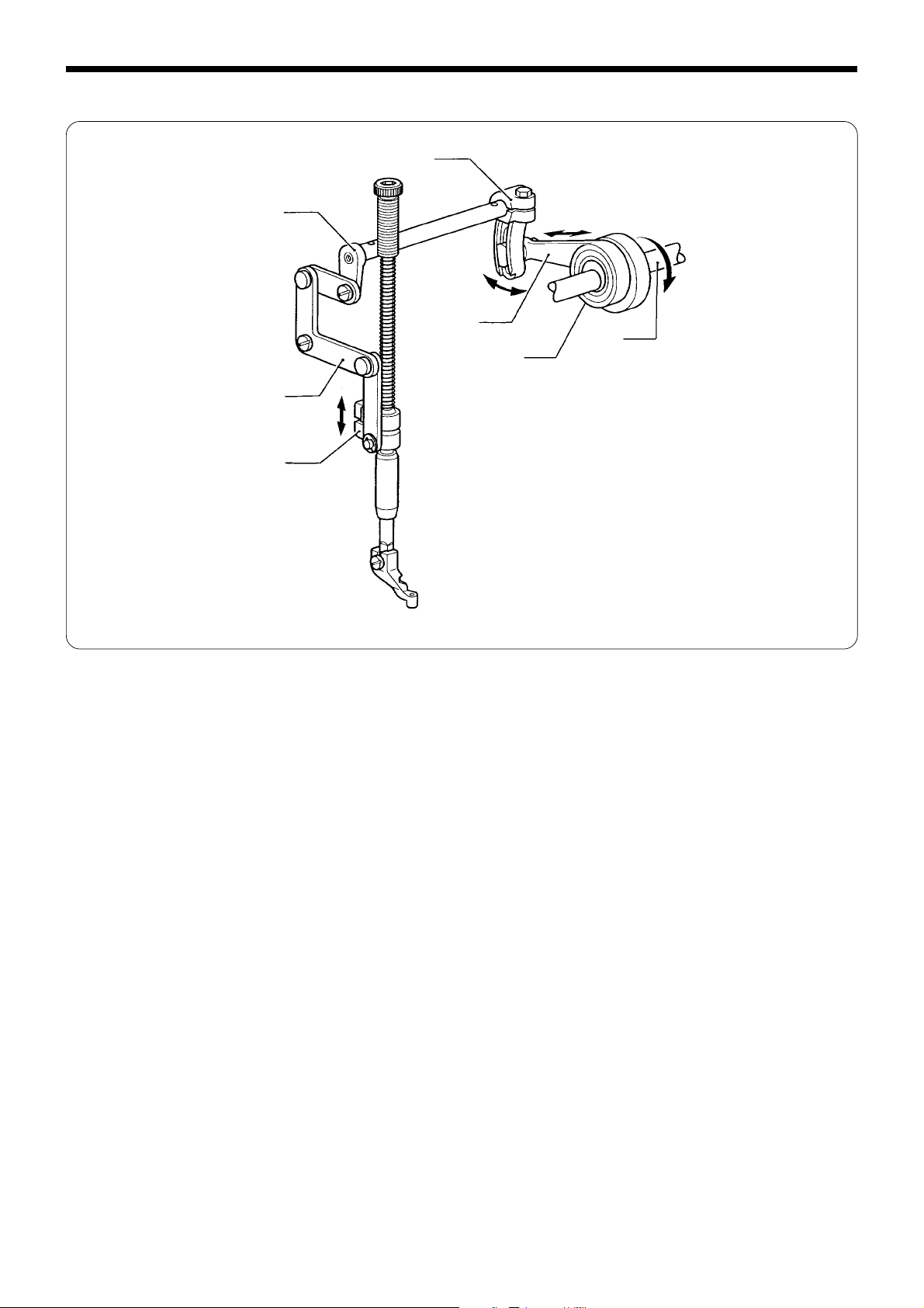
Presser foot mechanism (2)
r
Chapter 1. Mechanical description
e
q
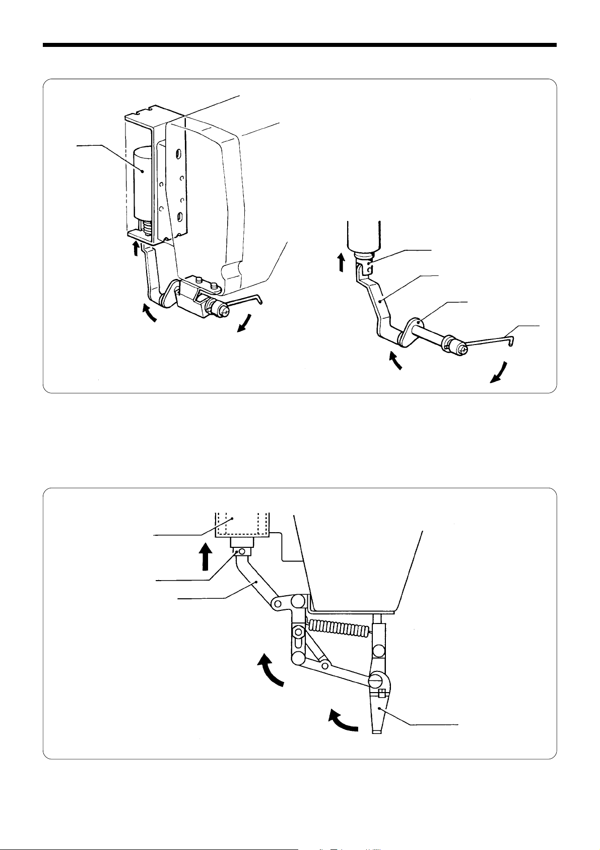
1. When the stepping work clamp signal is on, the stepping solenoid q operates the lifter lever w.
2. The lifter lever w operates the work clamp lifter lever assy r via the work clamp lifter wire e.
Note: When the machine stops, the stepping solenoid q operates, and the presser foot rises as soon as the work clamp
rises. At this time, tension releasing is performed.
w
BAS-311E.311EL.326E.326EL
7
Page 16
Chapter 1. Mechanical description
5. Thread trimmer mechanism
q
w
t
r
y
e
u
i
o
!1
!0
!2
!3
1. When the thread trimmer signal is on, the thread trimming solenoid q pushes the pushing lever driving lever w.
2. The pushing lever driving lever w pushes the thread trimmer driving lever r in the direction of the arrow, pivoting on
the shoulder screw e. The pushing lever driving lever w slides along the driving lever shaft t.
3. The roller y attached to the thread trimming driving lever r fits into the groove of the thread trimmer cam u, and
operates the thread trimmer rod i.
4. As the thread trimmer lever o is linked to the thread trimmer rod i, the connecting rod lever !0 operates.
5. When the thread trimmer connecting rod !1 linked to the connecting rod lever !0 operates, the fixed knife !2 and the
movable knife !3 fit into each other and perform thread trimming.
8
BAS-311E.311EL.326E.326EL
Page 17
Chapter 1. Mechanical description
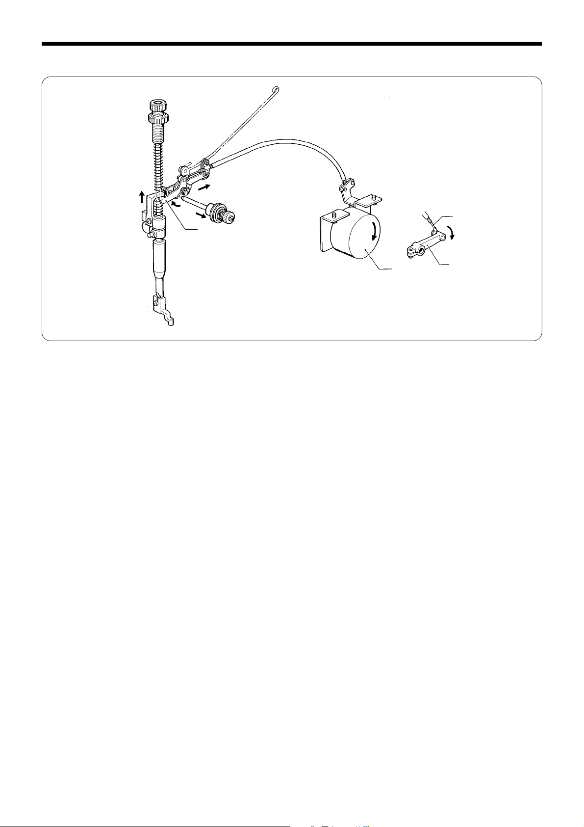
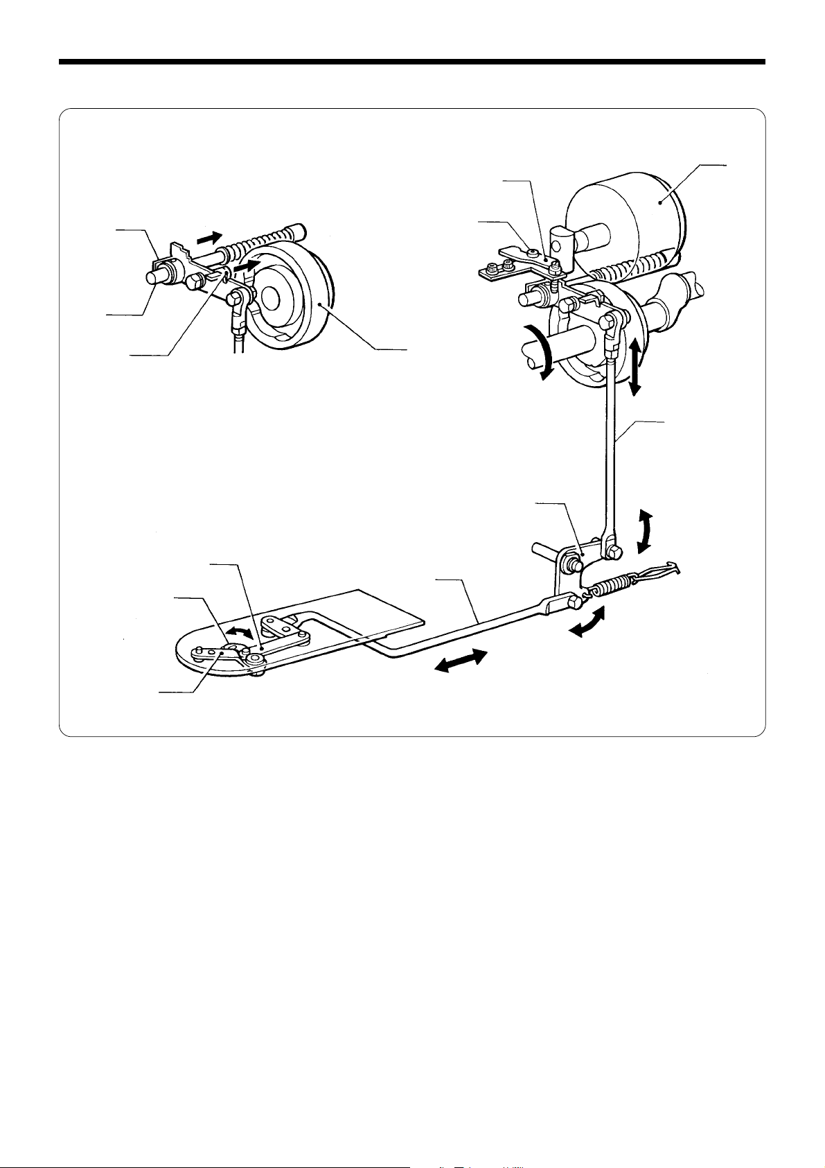
6. Thread nipper (1) when presser foot rises
r
e
r
q
1. When the machine stops, the stepping solenoid q operates, and the presser foot rises as soon as the work clamp rises.
2. The stepping solenoid q operates the lifter lever w, and the work clamp lifter lever assy e via the work clamp lifter
wire r.
w
Thread nipper (2) during thread trimming
q
w
e
t
y
r
1. When the thread trimming signal is on and the thread trimming solenoid operates, the thread trimmer driving lever q
is pushed in the direction of the arrow.
2. The thread trimmer driving lever q moves the tension release lever e via the tension release rod w.
3. The tension release lever e pushes the tension release bar r.
4. The end of the tension release bar r pushes the pin t and the tension disk opens y.
BAS-311E.311EL.326E.326EL
9
Page 18
Chapter 1. Mechanical description
7. Thread wiper (1) (vertical wiper: standard)
q
w
e
r
t
1. After thread trimming, the thread wiper signal is on and the thread wiper solenoid q operates.
2. When the plunger w operates in the direction of the arrow, the thread wiper crank assembly r attached to the end of
the thread wiper connecting rod e operates.
3. The wiper t attached to the thread wiper crank assembly r operates.
Thread wiper (2) (horizontal wiper: optional)
q
w
e
r
1. After thread trimming, the thread wiper signal is on and the thread wiper solenoid q operates.
2. When the plunger w operates in the direction of the arrow, T-wiper connecting rod assy S e also operates.
3. Thread wiper A r attached to T-wiper connecting rod assy e operates.
10
BAS-311E.311EL.326E.326EL
Page 19
Chapter 2. Disassembly
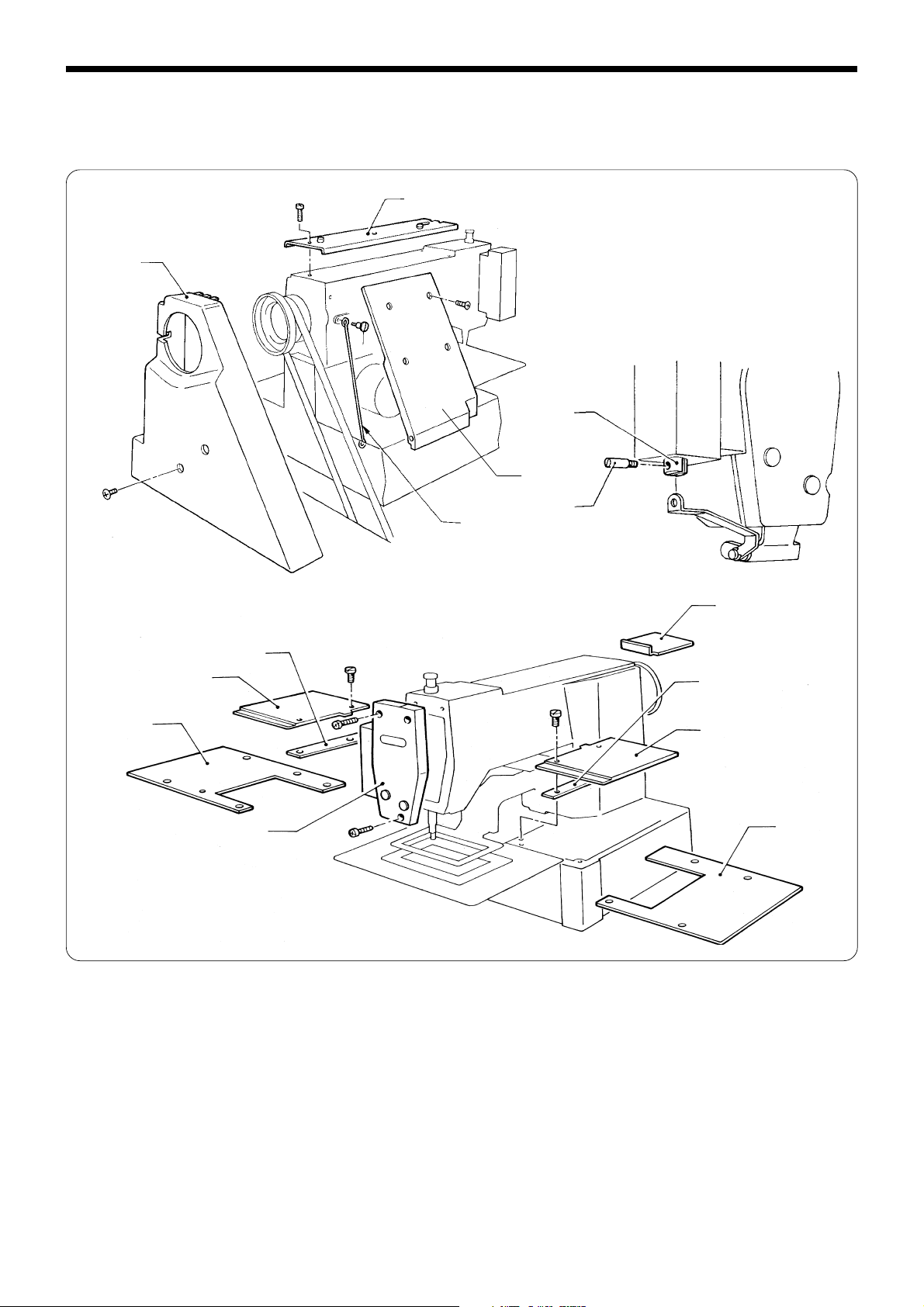
1. Covers (1) 311E
q
w
r
Chapter 2. Disassembly
y
e
!2
o
!0
i
u
t
!1
!0
o
!3
1. Remove the screw, the top cover q, the belt covers w and the rear cover e.
2. Loosen shoulder screw r and remove the work clamp lifter connect rod t.
3. Remove the plunger pin u from the plunger y.
4. Remove the screw and the face plate i.
5. Remove the screw and the X-feed bracket covers o on the right and left and cover spacer !0 Y-feed bracket cover !1.
6. Remove the screw and XY-feed base covers (L) !2 and (R) !3.
BAS-311E.311EL.326E.326EL
11
Page 20
Chapter 2. Disassembly
Covers (2) 311EL
!0
!1
o
t
y
u
r
q
e
i
w
u
o
1. Remove the screws, the top cover q, the belt cover w, and the frame side cover e.
2. Remove the plunger pin t from the plunger r.
3. Remove the screws, and the faceplate y.
4. Remove the screws, and X-axis feed bracket covers L and R u and Y- feed bracket cover i.
5. Loosen the screws, and remove the left and right feed bracket cover supports o in the direction of the arrow.
6. Remove the screws, and X-Y feed bracket covers L !0 and R !1.
Covers (3) 326E, 326EL
!0
!1
o
t
y
i
r
q
u
w
i
1. Remove the screws, the top cover q, the belt cover w, and the frame side cover e.
2. Remove the plunger pin t from the plunger r.
3. Remove the screws, and the faceplate y.
4. Remove the screws, and the bellows assy u.
5. Remove the screws and X-axis feed bracket cover assemblies L and R i.
6. Loosen the screws, and remove the left and right feed bracket cover supports o in the direction of the arrow.
7. Remove the screws, and X-Y feed bracket covers L !0 and R !1.
e
o
12
BAS-311E.311EL.326E.326EL
Page 21
2. Feed mechanism
Chapter 2. Disassembly
t
e
1. Remove the screw, the needle q and the presser foot w and finger guard e.
2. Remove the bolt and the work clamp r.
3. Remove the screw, the feed plate t and the needle sub plate y.
y
r
q
w
BAS-311E.311EL.326E.326EL
13
Page 22
Chapter 2. Disassembly
3. Presser foot mechanism
w
i
!1
!2
!0
q
e
r
t
!6
!5
o
!4
u
y
!3
1. Loosen the nut q, remove the adjust screw w, the spring guide e, and the spring r by lifting them from above of the
machine, and remove the washer t.
2. Loosen the bolt u of stepping work clamp arm R y, remove the shoulder screw i and the retaining ring !0 of the
presser bar lifter o from the faceplate, and then remove stepping work clamp arm F !1 and stepping link assy !2.
3. Push up the presser bar !3, and separate it from the presser bar bush !4.
(The presser bar lifter o, the cushion !5, and the needle bar clamp !6 will come off as a set.)
14
BAS-311E.311EL.326E.326EL
Page 23
4. Needle bar mechanism
t
Chapter 2. Disassembly
q
e
i
!1
!0
o
!5
!4
r
!7
u
y
!2
y
!6
r
w
!2
!3
!3
1. Remove the rubber cap q.
2. Remove the needle bar thread guide w from the needle bar e.
3. Loosen the screw of the needle bar clamp r, and remove the needle bar e through the machine top.
4. Remove the needle bar clamp r from the thread take-up lever t.
(Remove the needle bar guide slide block u from the needle bar guide y.)
5. Remove the rubber cap i, loosen the set screw o, and remove the thread take-up support stud !0.
6. Remove the oil cap !1, loosen the set screw !3 of the counter weight !2, and remove the thread take-up lever !4.
(The thread take-up assembly !5 will come off.)
7. Remove the rubber cap !6, the screw !7, and the needle bar guide y.
(Do not remove them if possible to prevent the machine from overheating due to needle bar rubbing.)
BAS-311E.311EL.326E.326EL
15
Page 24
Chapter 2. Disassembly
5. Upper shaft mechanism
e
w
q
r
!0
!1
o
r
t
y
u
i
!2
!0’
r
!6
!7
!5
r
!2
q
!1
!4
!3
1. Loosen the screw w and the set screw e of thread take-up crank q.
(The screw w should be loosened until its end comes off the upper shaft r.)
2. Remove the screw t, and the thread trimming solenoid y.
3. Remove the screw u, and the wick support i.
4. Remove the screw o, and the crank rod !0.
(At this time, lower the crank rod !0’ in the direction of the arrow.)
5. Loosen the set screws of the stepping work clamp cam !1 and the thread trimmer cam !2.
6. Remove the V belt !3, loosen the set screw !4, and remove the pulley !5.
7. Remove the screw !6 and the synchronizer !7.
8. Remove the upper shaft r in the direction of the arrow.
After that, remove the thread take-up crank q, the stepping work clamp cam !1, and the thread trimmer cam !2 from
the upper shaft r, in this order.
16
BAS-311E.311EL.326E.326EL
Page 25
6. Feed mechanism (Y axis) (1) 311E and 311EL
w
q
Chapter 2. Disassembly
e
r
t
1. Loosen the set screw and remove the X-feed shaft q.
2. Remove the screws and the work clamp arm w.
3. Tilt the machine head until it stops.
4. Remove the bolt of the Y-driving shaft holder e, the Y-driving shaft r and the X-feed shaft support t.
5. Raise the machine head.
BAS-311E.311EL.326E.326EL
17
Page 26
Chapter 2. Disassembly
Feed mechanism (Y axis) (2)
r
q
w
e
!3
w
q
t
!6
!5
y
!2
!4
!6
u
i
o
!8
!9
!1
!0
!7
1. Remove the bolts, the Y-feed guide assembly q, the cross roller w, and the Y-feed bracket e.
2. Remove the screws, the X-feed bracket r, and the linear guide t.
3. Remove the bolts and the Y-driving pulse motor bracket y.
4. Remove the bolts and the Y-pulse motor u.
5. Loosen the set screws of the idle gear i and timing pulley A o, and remove Y-pulley shaft A !0 along with the retaining
rings. (The idle gear i, timing pulley A o, and the ball bearing !1 will come off.)
6. Loosen the set screw of timing pulley A !2, and remove the two retaining rings and Y-pulley shaft B !3.
7. Remove the bolts, the Y-driving pulse motor bracket !4, timing pulley A !2, the Y-timing belt !5, and micro bearings !6.
* To remove the Y-driving shaft holder !7, remove the bolt, the belt holder !8, the timing belt spacer, !9, and the Y-
timing belt !5.
18
BAS-311E.311EL.326E.326EL
Page 27
Feed mechanism (Y axis) (3) 326E, 326E
r
w
e
q
q
Chapter 2. Disassembly
u
!1
i
t
y
!0
!2
o
!3
!4
1. Secure the slider support shaft w of the work clamp assy q using the supplied set screw e.
(To prevent the slider support shaft w and the slider r from suddenly protruding, be sure to do this job.)
2. Loosen the set screw, and remove the X-feed shaft t.
3. Remove the two bolts, and the work clamp assy q.
4. Remove the two bolts, and X-feed shaft support 326 y.
5. Remove the four bolts, the Y-feed pulse motor bracket u, and the Y-driving shaft i.
6. Remove the two bolts, and Y-feed bracket cover F o.
7. Remove the four bolts, Y-feed guide assy 326 !0, cross roller 326 !1, and the Y-feed bracket !2.
8. Remove the eight set screws, the X-feed bracket !3, and the linear guide !4.
BAS-311E.311EL.326E.326EL
19
Page 28
Chapter 2. Disassembly
7. Feed mechanism (X axis) (1) 311E
q
y
t
w
e
!0
r
!5
!6
i
y
!4
!3
!1
i
o
!2
!0
u
1. Remove the rubber cap q.
2. Loosen the set screws of X-timing pulley B311 w and timing pulley A e, and remove the X-timing pulley shaft t and
retaining ring r. (X-timing pulley B311 w and timing pulley A e, and the two ball bearings y will come off.)
3. Loosen the set screw of timing pulley B u, and remove the retaining ring i and X-pulley shaft B o.
(Timing pulley B u, X-timing belt B311 !0, and the two ball bearings !1 will come off.)
4. Remove the bolts !2 from adjustment holes, and separate X-pulley base B !3.
5. To remove the X-feed bracket !4, remove the eight set screws, the belt holder !5, the timing belt spacer !6, and X-timing
belt B311 !0.
20
BAS-311E.311EL.326E.326EL
Page 29

Chapter 2. Disassembly
Feed mechanism (X axis) (2) 311EL and 326E, 326EL
@3
o
!1
!0
!3
!6
!2
!5
!4
!7
!8
y
u
!9
q
r
!7
r
w
e
@6
@2
@0
@5
@4
@1
t
@2
i
1. Remove the bolt w and the washer e of X-pulley bracket L q, and the adjust bolt r.
2. Remove the bolt y and the washer u of X-pulley bracket R t, and the adjust bolt i.
3. Remove X-timing belt A326 o.
4. Loosen the set screw !1 of X-timing pulley B326 !0, and the set screw !3 of timing pulley A !2, and remove the back
retaining ring !5 of the X-timing pulley shaft !4, and pull out the X-timing pulley shaft !4 in the direction of the arrow.
(At this time, timing pulley !2, X-timing belt B326 !6, X-timing pulley B326 !0, X-timing belt A326 o, and the two micro
bearings !7 will come off.)
5. Loosen the set screw !9 of timing pulley B !8, remove the front retaining ring @1 of X-pulley shaft R @0, and pull out X-
pulley shaft R @0 in the direction of the arrow.
(At this time, X-timing belt B326 !6, timing pulley B !8, and the two micro bearings @2 will come off.)
6. Remove the bolt @4 on the back of the X-feed bracket @3, the belt holder @5, the timing belt spacer @6, and X-timing belt
B326 !6.
BAS-311E.311EL.326E.326EL
21
Page 30

Chapter 2. Disassembly
8. Lower shaft mechanism
u
y
w
t
r
q
e
!2
!1
!0
o
i
1. Tilt the machine head until it stops.
2. Remove the bobbin case q and the shuttle hook w.
3. Loosen the bolt e, and remove the driver r and the retaining ring t.
4. Loosen the set screw of the set screw collar y, and remove the lower shaft assembly u from the rear of the machine.
5. Loosen the set screw i.
6. Loosen the set screw of the set screw collar o, and remove the rock gear shaft !0 from the rear of the machine.
7. Remove the set screw collar o, the rock gear !1, and the crank rod !2.
8. Raise the machine head.
22
BAS-311E.311EL.326E.326EL
Page 31

9. Work clamp lifter (Solenoid type)
e
Chapter 2. Disassembly
w
u
o
i
!1
!3
!0
q
t
u
q
!0
!2
e
r
y
i
r
!5
!4
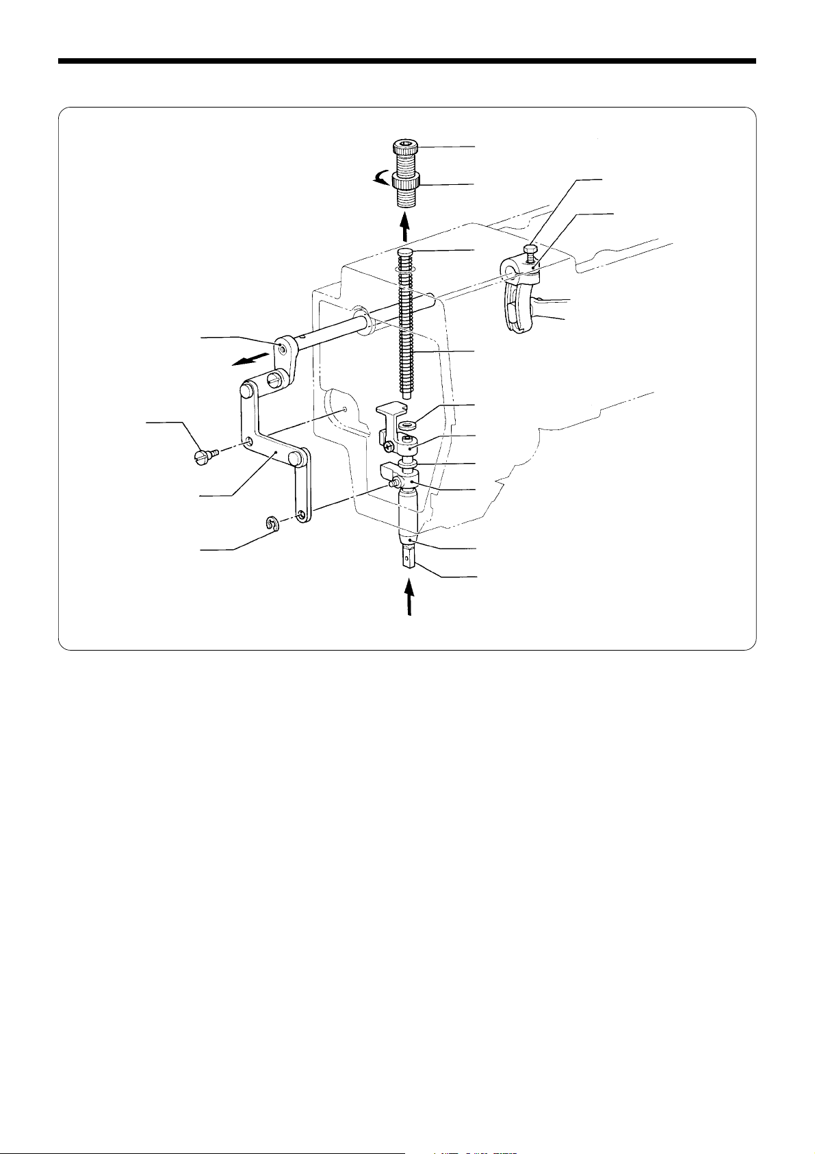
1. Remove the spring q.
2. Remove the screw w, and the presser solenoid e from the plunger r by lifting the latter from above.
Be sure to hold the plunger r securely so that it does not fall.
3. Remove the snap pin t and the rod y.
4. Loosen the set screw u, and remove the snap pin i, link shaft A o, and the washer !0.
5. Remove the rubber cap !1, the snap pin !2, and link shaft C !3.
Be sure to hold the presser plate !4 and the presser bar lifter lever rubber !5 so that they do not fall.
6. Remove all parts connected to the plunger r by lifting them upward.
o
BAS-311E.311EL.326E.326EL
23
Page 32

Chapter 2. Disassembly
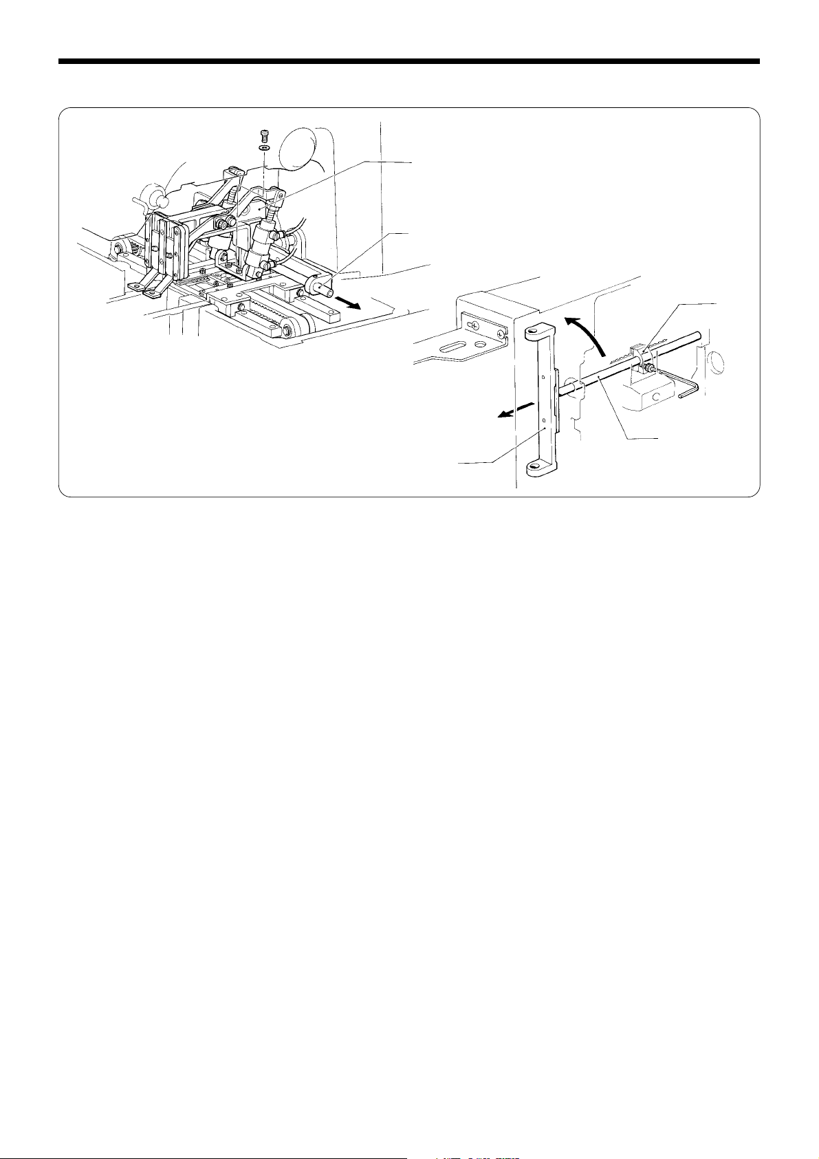
10. Thread nipper mechanism
r
r
t
y
i
e
t
r
w
q
u
y
o
!2
!3
!1
!0
1. Remove the set screw, the thread tension q, the pin w, and the tension release bar e.
2. Remove the shoulder screw r and the tension release rod t.
3. Remove the screw and the tension release assembly y.
4. Remove the screw, the cable support u, and the cord holder i.
5. Tilt the machine head until it stops.
6. Remove the extension spring o and the SOL oil pan !0.
7. Remove the screw and the wire support !1.
8. Loosen the bolt, and remove the work clamp lifter lever !2.
9. Loosen the set screw of the work clamp lifter lever !2, and remove the flanged shaft !3.
10.Return the machine head to its original position.
24
BAS-311E.311EL.326E.326EL
Page 33

11. Thread trimmer mechanism
Chapter 2. Disassembly
@1
t
q
y
r
w
e
i
!1
@2
o
!2
!0
u
!6
!9
!4
@0
!3
!7
!7
!5
!8
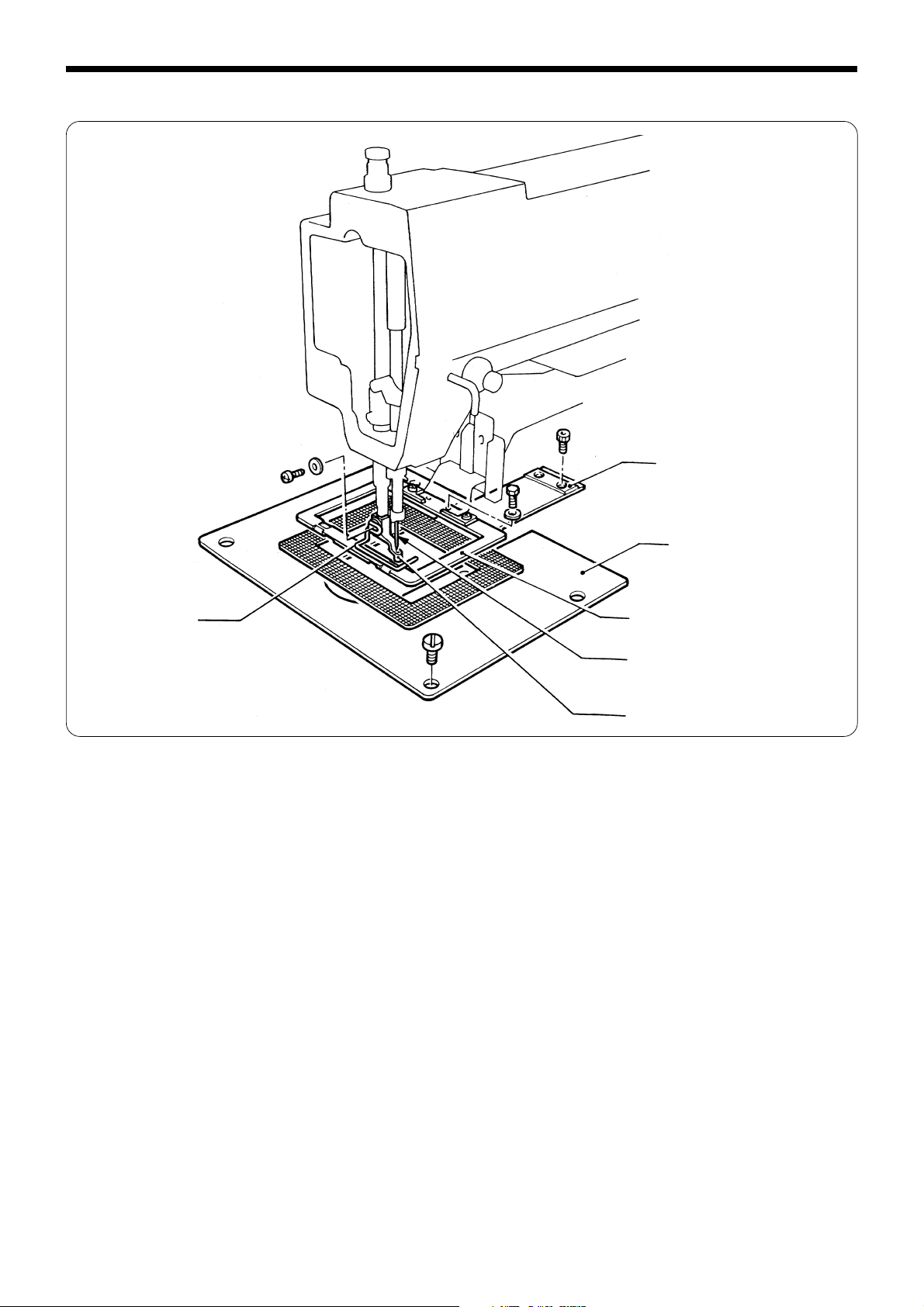
1. Remove the screws q, the flat screws w and the needle plate e.
2. Remove the rubber cap r, loosen the set screw t, and remove the connecting rod lever shaft y.
3. Remove the oil cap u, loosen the set screw i, and remove the retaining ring o.
4. Remove the driving lever shaft !0 by pulling it in the direction of the arrow. Then remove the cushion !1 and the spring
!2 from the shaft.
5. Tilt the machine head until it stops.
6. Remove the thread trimmer return spring !3 and the spring hook !4.
7. Remove the nut !5, the shoulder screw !6, and the washer !7.
8. Loosen the set screw !8, and remove the lever shaft !9 and the thread trimmer lever @0.
9. Return the machine head to its original position, and remove the connecting rod lever @1 and the thread trimmer
driving lever @2.
BAS-311E.311EL.326E.326EL
25
Page 34

Chapter 3. Assembly
Chapter 3. Assembly
1. Thread trimmer mechanism (1)
y
r
e
!5
t
w
u
q
!3
!5
i
!0
!9
@7
o
@3
@6
@5
@4
!1
r
y
e
1. Insert the driving lever shaft q into the machine. Place the spring w, the thread trimmer driving lever e, and the
cushion r on the shaft in this order.
2. Put the retaining rings t on the shaft. Press the thread trimmer driving lever e against the retaining rings t. Tighten
the set screw y on the screw flat.
3. Attach the oil cap u.
4. Insert the connecting rod lever i into the machine, lightly press the connecting rod lever shaft o against the former,
then secure them using the set screw !0.
5. Attach the rubber cap !1.
6. Tilt the machine head until it stops.
7. Pass the lever shaft !3 with the washer and the retaining ring, through the thread trimmer lever !2, and tighten the set
screw !4 on the screw flat.
8. Attach the thread trimmer rod !5 and the connecting rod lever i to the thread trimmer lever !2 using the washer !6,
plain washer 4.37 (t=0.8) !7, washer 4.76 (t=0.5) !8, the stud screw !9, and the nut @0.
9. Attach the spring hook @1 to the inside of the machine, and connect the thread trimmer return spring @2 to it.
10.Return the machine head to its original position.
11.Fit the thread cutter connecting rod @3 on connecting lever pin @4 , and install needle plate @5 using the flat screws @6
and screws @7 (First tighten the flat screws @6 and screws @7 ).
t
!2
i
!8
!7
!4
@0
!6
@2
@1
26
BAS-311E.311EL.326E.326EL
Page 35

2. Thread nipper mechanism
q
u
y
Chapter 3. Assembly
1. Pass the tension release assembly q from the bottom of
the machine to the top.
2. Attach the wire support w to the solenoid set plate e
with the bolt r.
3. Temporarily attach the lifter lever t to the shaft of the
stepping solenoid y. At this time, align the end face of
the lifter lever t with the end face of the stepping solenoid y.
4. Attach the SOL oil pan u using the screw.
5. Raise the machine head.
e
!0
i
y
t
t
!1
Align
w
r
6. Attach the cable support i to the machine body.
7. Attach the thread trimmer rod o to the tension release
assembly q with the shoulder screw !0.
8. Attach the other end of the tension release rod o to the
thread trimmer driving lever !1 using the shoulder screw
!0.
q
!0
o
!3
BAS-311E.311EL.326E.326EL
27
Page 36

Chapter 3. Assembly
!2
9. Attach the tension release assembly q to the machine
body with the screw !2.
10.Attach the cord holder !3 to the machine body.
q
11.Attach the tension release bar !4, the pin !5 and the
thread tension assembly !6 to the machine. Fit the set
screw !7 in the groove of the thread tension assembly
!6, then tighten it.
@0
!7
!9
@1
@2
t
!4
!8
!5
!6
12.Turn the stepping solenoid !8 fully in the direction of
the arrow. Move the lifter lever t so that there is no
clearance (0 mm) between work clamp lifter lever !9
and the presser bar clamp @0, remove the slack from the
work clamp lifter wire @1, and tighten the bolt @2.
28
@0
!9
BAS-311E.311EL.326E.326EL
Page 37

3. Work clamp lifter mechanism
Chapter 3. Assembly
!6
@4
t
!5
!7
@3
y
!4
!0
w
i
o
@0
u
q
@0
!1
!3
e
@2
i
@1
!2
e
r
!3
@0
!7
!8
!7
!9
!4
79.0mm
1. Attach the presser plate q to the presser bar lifter lever rubber w, and insert them from the bottom of the arm. Insert
the parts r linked to the plunger e from the top of the arm, and fit them on link shaft C t, link B y, and the presser
plate q.
2. Fit the snap pins u on both ends of link shaft C t.
3. Insert link shaft A i into the machine, and pass it through the washer o and link A !0.
4. Fit the snap pins !1 on both sides of link shaft A i and outside the washer o.
5. Attach the presser solenoid !2 to the top of the arm so as to cover the plunger e. Secure link shaft A i using the set
screw !4 so that link B y is centered in the bush !3.
6. Slide the presser solenoid !5 until it has reached 19.0 mm from the end of the arm, where the plunger e easily moves,
and tighten the screw !6.
7. Attach the spring !7 to link shaft B !8 and the pin !9.
8. Hang the rod @0 on the shoulder screw @1, and insert the former into link shaft B @2, and secure it using the snap pins @3.
9. Attach the rubber cap @4.
!1
BAS-311E.311EL.326E.326EL
29
Page 38

Chapter 3. Assembly
Make sure that work clamp easily moves up and down, and apply grease to sliding portions to assemble parts.
t
i
1. Sliding portions of link shaft C q and link B w.
2. Sliding portions of link shaft B e, link B w, link A r, and
link C t.
3. Sliding portions of link shaft A y and link A r.
4. Sliding portions of link shaft D u, link C t, and plunger
i.
u
r
y
t
e
i
u
w
q
q
1. Sliding portion of the work clamp q (Apply small
amount of grease).
2. Sliding portions of the work clamp arm lever shaft w
and work clamp arm levers R and L e.
e
w
30
BAS-311E.311EL.326E.326EL
Page 39

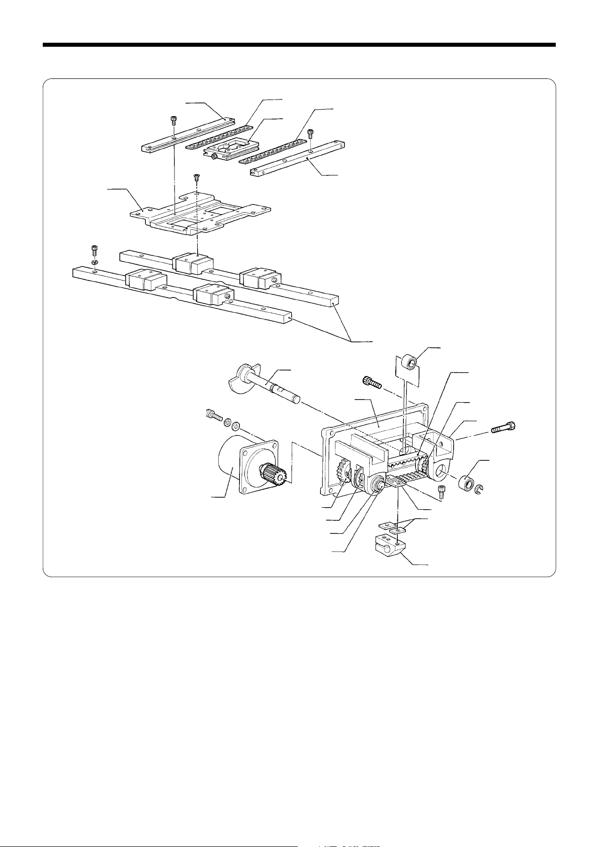
4. Feed mechanism (X axis) 311E
1. Fit the ball bearings q on X-pulley bracket L, and pass
q
e
t
y
u
q
Chapter 3. Assembly
the X-timing pulley shaft w from the front of X-pulley
bracket L through timing pulley A e, X-timing belt B311
r, X-timing pulley B326 t, and X-timing belt A326 y.
Place the two retaining rings u on both ends of the Xtiming pulley shaft w by pressing them against the ball
bearings q, adjust timing pulley A e so that there is no
looseness in the X-timing pulley shaft w, and secure it
using the set screws.
e
w
r
i
t
o
!2
!3
2. Secure X-timing pulley B326 t on the screw flat using
the set screw.
3. Loop the X-timing belt B i around timing pulley (B) !1.
Pass X-pulley shaft (B) !0 through timing pulley (B) !1,
and the micro bearing !2. Secure them to the X-pulley
base B o using the retaining ring !3.
!0
!3
!2
!1
!4
4. Place timing pulley (B) !1 at the middle of X-pulley base
!1
o
BAS-311E.311EL.326E.326EL
(B) o, then tighten the two set screws !4.
31
Page 40

Chapter 3. Assembly
!7
i
!6
!7
Reference
area
!6
!5
5. Attach the linear guide !5, the X-feed bracket !6, and the
X-feed guide !7 to the bed using the three bolts !8.
Note: Adjust the X-feed guide !7 so that the X-feed
bracket !6 can easily move left or right.
Adjustment procedure
1. Position the front linear guide !9 in the reference area
for installation on the front of the bed, and secure it
using the six bolts @0 and six washers.
2. Attach the rear linear guide @1 to the rear of the bed
using the five bolts @2 and five washers. Keep in
mind that the linear guide can move easily.
3. Attach the X-feed bracket !6 to the linear guide !5 us-
ing the eight screws.
4. Adjust the rear linear guide @1 so that the X-feed
bracket !6 can easily move left and right, and tighten
the five bolts @2 on the rear linear guide.
5. Place X-timing belt B i between the two timing belt
spacers !9 on the back of the X-feed bracket !6. Align
a rectangular slot of the belt holder !8 with a tooth of
X-timing belt B i. and secure them using the belt @0.
9.8N
(1kgf)
!9
!8
i
@0
6. Move the X-feed bracket !6 to the left end and apply a
load of 9.8N (1 kgf) to the center of the X-timing belt B i.
Then adjust the X-timing belt B i with the adjust screw
@1 to produce a deflection of 3 mm.
!6
3mm
@1
80mm
32
BAS-311E.311EL.326E.326EL
Page 41

Feed mechanism (X axis) 311EL, 326E
q
!2
!6
Chapter 3. Assembly
w
!3
!5
e
!4
!7
o
!1
!4
r
i
u
t
i
!0
1. Place X-timing belt B326 w between the two timing belt spacers e on the back of the X-feed bracket q. Align a
rectangular slot of the belt holder r with a tooth of X-timing belt B326 w, and secure them using the bolt t.
2. Fit timing X-timing belt B326 w in X-pulley bracket R y, pass X-pulley shaft R u through the micro bearing i, timing
pulley B o, and the micro bearing i, and attach the retaining ring !0.
3. Place X-timing belt B326 w and X-timing belt A326 !2 on X-pulley bracket L !1, pass the X-timing pulley shaft !3
through the micro bearing !4, timing pulley A !5, X-timing pulley B326 !6, and the micro bearing !4, and attach the
retaining ring !7.
y
BAS-311E.311EL.326E.326EL
33
Page 42

Chapter 3. Assembly
Feed mechanism (X axis) 311EL and 326E
@3
@7
!6
@7
!8
!9
@4
!1
!3
!5
2mm
2.5mm
!2
w
@2
o
@1
@0
@6
@5
u
y
@8
4. Position X-timing pulley B326 !6, which is attached to X-pulley bracket L !1 via the X-timing pulley shaft !3, so that there
is a 2 mm clearance between the top of X-timing pulley B326 !6 and end A of X-pulley base L !1. Position timing pulley
A !5 so that there is a 2.5 mm clearance between the bottom of timing pulley A !5 and end B of X-pulley base L !1. Then
secure X-timing pulley B326 !6 and timing pulley A !5 to the X-timing pulley shaft !3 using the set screws !8 and !9.
5. Position timing pulley B o attached to X-pulley bracket R y so that clearances C and D are equal, then secure it to Xpulley shaft R u using the set screw @0.
6. Loop X-timing belt A326 !2 around X-timing pulley A311 (A326) @2 of X-pulse motor @1 and X-timing pulley B326 !6.
Temporarily attach X-pulley bracket L !1 to the bed using the bolt @3 and washer @4.
7. Loop X-timing belt B326 w around timing pulley A !5 of X-pulley base L !1 and timing pulley B o of X-pulley base R y.
Temporarily attach X-pulley bracket R y to the bed using the bolt @5 and washer @6.
8. Insert the bolt @7 that is used to adjust the tension of X-timing belt A326 !2 from the left side of the bed, into X-pulley
bracket L !1.
9. Insert the bolt @8 that is used to adjust the tension of X-pulley belt B326 w from the right side of the bed, into X-pulley
bracket R y.
34
BAS-311E.311EL.326E.326EL
Page 43

Feed mechanism (Y axis) 311E and 311EL
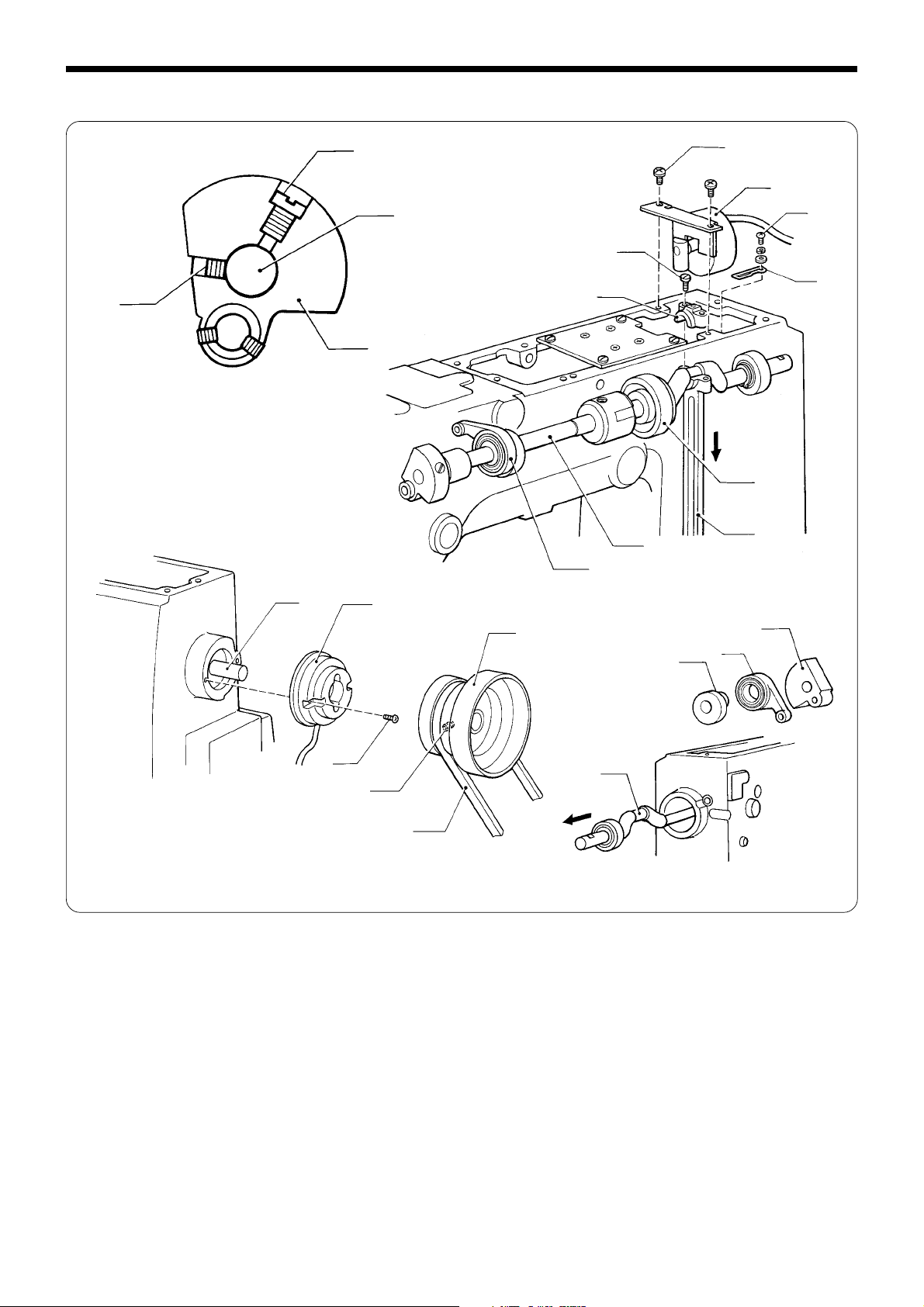
1. Loop the Y-timing belt q around the Y-driving pulse motor bracket w, and pass Y-pulley shaft B e through the
Y-driving pulse motor bracket w, timing pulley A r, and
the micro bearing t. Attach the retaining ring y to hold
them.
2. Insert Y-pulley shaft A i into the Y-driving pulse motor
base u, passing it through timing pulley A o, the ball
bearing !0, and the idle gear !1. Position the idle gear !1
so that there is no end play with it.
3. Secure timing pulley A r with a clearance of 0.5 mm
from the Y-driving pulse motor bracket w left.
4. Secure timing pulley A o with the set screw !2 to provide a 0.5 mm clearance with the Y-driving pulse motor
base u.
q
o
!1
!0
!0
e
i
0.5mm
t
r
u
t
w
y
u
0.5mm
Chapter 3. Assembly
!3
u
!5
!4
!1
r
w
!6
q
!2
u
!8
!7
o
w
!9
5. Lightly pressing the driving gear !4 of the Y-pulse motor
!3 against the idle gear !1, attach the Y-pulse motor !3 to
the Y-driving pulse motor base u.
Note: Make sure that there is no backlash between the
idle gear !1 and the driving gear !4.
6. Temporarily attach the Y-driving pulse motor bracket w
to the Y-driving pulse motor base u using the bolts !5.
7. Sandwich the timing belt spacers !7 between the Y-tim-
ing belt q and the Y-driving shaft holder !6, place the
belt holder !8 on the Y-timing belt q, and secure the Ytiming belt q to the Y-driving shaft holder !6.
8. Lightly pressing the assembled Y-driving pulse motor
base u against end A of the machine, secure it with the
screws.
“A”
BAS-311E.311EL.326E.326EL
35
Page 44

Chapter 3. Assembly
@3
@9
#2
@8
9. Attach the Y-axis feed guide @0 to the left of the X-feed
bracket @1, pressing the former against the latter.
10.Attach the Y-axis feed bracket @2, the cross roller @3, and
the right of the Y-axis feed guide @4 right of the to the Xfeed bracket @1.
Note: When attaching the Y-axis feed guide @4 to the
right of the X-feed bracket @1, lightly push it to the
left so that there is no looseness in the Y-axis feed
guide @2, and tighten the set screw @5.
#0
w
@0
@2
Parallel
@8
@6
@1
q
@4
!6
@6
@5
Line
#1
@9
!6
@7
11.Tilt the machine head until it stops.
12.Pass the Y-driving shaft @6 through the Y-driving shaft
holder !6.
Align the reference line on the Y-driving shaft @6 with the
end of the Y-driving shaft holder !6.
Then, tighten the bolt @7.
Note: Be sure to make the X-feed shaft support @8 paral-
lel to the top of the bed to prevent timing belt (Y)
q from being damaged or cut.
13.Raise the machine head.
14.Temporarily attach the presser arm @9 to the Y-feed
bracket @2 with the screw #0.
15.Pass the X-feed shaft #1 through the X-feed shaft support @8 and the presser arm @9, then secure it with the set
screw #2.
16.Loosen the bolt !5 of the driving P motor bracket w.
When the power is turned off, adjust the driving P motor
bracket w with the adjust bolt !5 so that timing belt (Y)
q is not slack and the presser arm @9 moves smoothly
forwards and backwards. Then power on the machine
and adjust the tension of timing belt (Y) q with the adjust bolt #3 so that there is no looseness of the presser
arm @9.
17.After adjustment, tighten the bolt !5 of the driving P motor bracket w.
36
#3
!5
BAS-311E.311EL.326E.326EL
Page 45

Feed mechanism (Y axis) 326E
q
Chapter 3. Assembly
r
w
e
Rack
25 - 44N (2.5 - 4.5kgf)
1. Engage the driving gear w embedded in the Y-feed pulse motor bracket q with the rack of the Y-driving shaft e.
2. The engagement load between the driving gear w embedded in the Y-feed pulse motor bracket q with the rack of the
Y-driving shaft e should be 25 - 44 N ( 2.5 - 4.5 kgf) or less (so that the load will not fluctuate sharply). Move the Y-feed
pulse motor bracket q vertically to adjust the load, and secure it using the bolts r.
t
i
o
o
!0
y
u
!1
3. Attach the Y-axis feed guide t to the left of the X-feed bracket y, pressing the former against u the latter.
4. Attach the Y-feed bracket i, the cross roller o, and the right Y-feed guide !0.
When attaching the right Y-feed guide !0 to the right of the X-feed bracket y, lightly pushing it to the left so that there
is no looseness in the Y-feed bracket i, and tighten the bolt and set screw !1.
BAS-311E.311EL.326E.326EL
37
Page 46

Chapter 3. Assembly
!5
!2
e
!3
!4
i
5. Temporarily attach the work clamp Arm !2 to the Y-feed bracket i using the bolts and washers.
6. Temporarily attach the X-feed shaft support !3 to the Y-driving shaft e using the bolts and washers.
7. Pass the X-feed shaft !4 through the X-feed shaft support !3 and the work clamp Arm !2, and secure the X-feed shaft
support !3 and the X-feed shaft !4 using the set screws.
8. Move the work clamp Arm !2 left and right to make sure that there is no inclination in X-feed shaft !4. Then securely
tighten the bolts of Y-driving shaft e and the X-feed shaft support !3.
9. Remove the set screw of the slider support shaft !5 from the front of the work clamp Arm !2.
38
BAS-311E.311EL.326E.326EL
Page 47

6. Upper shaft mechanism
Chapter 3. Assembly
e
i
q
w
!0
t
y
r
e
q
y
t
q
r
o
!1
0.5mm
!1
u
!0
q
w
!0
i
1. Insert the upper shaft q from the rear of the machine, and place the thread trimmer cam w and the stepping work
clamp connecting rod e on the shaft.
* Apply adhesive (equivalent of Three Bond 1401) around the area which the bearing in the machine goes into. Also,
apply grease to grooves on the thread trimmer cam w.
2. Pass the thread take-up crank r from the face plate side over the upper shaft q, and tighten the screw t and the set
screw y.
3. Place the upper shaft bush between the thread take-up crank r and the stepping work clamp connecting rod e, and
secure the upper shaft q so that there is no looseness. (At this time, do not securely tighten the set screw of the
stepping work clamp conncting rod e.)
4. Press the thread trimmer conncting rod w against the crank of the upper shaft q. Adjust the set screw u that comes
first when rotating to the screw flat, and tighten it.
5. Attach they synchronizer i to the machine using the screw o.
6. Attach the pulley !0 leaving a 0.5 mm clearance from the protrusion of the synchronizer i, tighten the set screw !1 that
comes later when rotating to the screw flat.
BAS-311E.311EL.326E.326EL
39
Page 48

Chapter 3. Assembly
7. Needle bar mechanism
t
!7
!6
u
!8
e
i
r
!2
y
o
w
q
u
!9
aDP×5
!3
!2
!1
!0
!4
ADP×17
q
!3
!1
!5
!3
@0
!4
Cut section
1. Temporarily tighten the screw w of the needle bar guide q.
2. Pass the thread take-up support stud e through the thread take-up assembly r, lightly press the former, and secure
them using the set screw t.
3. Pass the needle bar crank y through the thread take-up assembly r and the counter crank u, adjust the set screw i
to the screw flat, and tighten the set screws i and o.
4. Fit the chamfering side of the needle bar guide slide block !0 into the groove on the needle bar guide q, and insert the
shafts of the needle bar clamp !1 into the needle bar connecting rod !2 and the needle bar guide slide block !0, as
shown in the figure.
5. Insert the needle bar !3 from the top of the machine into the needle bar clamp !1.
6. Turn the pulley to set the needle bar !3 at its lowest position. Move the needle bar vertically so as to align the second
lowest reference line A (for using needle DP ✕ 17) or the highest reference line a (for using needle DP ✕ 5) on the
needle bar !3 with the lower end of needle bar bush (D) !4. Tighten the screw !5 with the cut section of the needle bar
facing the front.
7. Find the position of the needle bar guide q so that the pulley rotates easily, and tighten the screw w.
8. Attach the oil cap !6 and the rubber caps !7, !8, and !9.
9. Fit the needle bar thread guide @0 on the needle bar !3.
40
BAS-311E.311EL.326E.326EL
Page 49

8. Presser foot mechanism
Chapter 3. Assembly
o
!5
!1
!6
!7
!2
!0
u
y
i
t
r
e
q
w
!4
!3
32mm
1. Insert the presser bar w into the presser bar bush q. Pass the presser bar lifter e, the cushion r, and the needle bar
clamp t through the presser bar w in that order.
2. Secure the needle bar clamp t with the screw.
3. Insert the spring y and the spring guide u from the top of the arm, pass the spring guide u through the washer i and
the presser bar w, and attach the presser adjusting screw o.
Note: Position the presser adjusting screw o using the presser adjusting nut !0 so that there is approx. 32 mm from the
top of the presser adjusting screw o to the top of the machine.
4. Pass stepping work clamp arm F !1 through spreader shaft bushes (L) and (R) !2, then insert it into stepping work clamp
arm R !3.
5. Attach the stepping link assy !6 to the arm using the shoulder screw !5, and to the presser bar lifter e using the
retaining ring !7.
BAS-311E.311EL.326E.326EL
41
Page 50

Chapter 3. Assembly
V notch
t
!1
!1
!6
0.5 - 1mm
!4
e
q
6. Turn the pulley to align the needle bar with the shuttle
hook. At this time, turn the stepping work clamp connecting rod !8 to turn stepping work clamp arm F !1 in
the direction of the arrow and move the stepping link
assy !6 in the direction of the arrow. When the presser
foot is at the lowest position, secure the stepping work
clamp connecting rod !8 to the upper shaft @0 using the
set screw !9.
Adjust the lift stroke of presser foot A to 3-5 mm, and 5-8
mm. When the clearance between the presser bar lifter
e and the presser bar bush q is 0.5 - 1 mm, tighten the
bolt !4 of stepping work clamp arm R !3. (At this time,
the match mark of stepping work clamp arm F !1 will be
almost aligned with that of arm.)
Note: Make sure that stepping work clamp arm F !0 has
no end play.
!3
Align
w
@1
w
!9
!8
@3
@2
@0
w
@1
@2
7. Secure the needle bar clamp t using the screw so that
when the presser bar w is at the lowest position. The
distance between the bottom of the presser bar w and
the top of the needle plate should be 23 mm. (22 mm for
311EL.)
Attach the presser foot @1 to the presser bar w so that
the top of the presser foot @1 is aligned with the top of
the screw that holds the presser foot @2.
8. Attach the needle @2 to the needle bar @3.
9. Turn the pulley to insert the needle @2 into the hole of the
presser foot @1. Turn the presser bar w so that the
needle @2 is in the center of the hole of the presser foot
@1, and tighten the screw of the needle bar clamp t.
10.Turn the pulley to set the presser bar w at its lowest position. Adjust the height of the presser foot @1 so that
there is a 0.5 mm clearance from the top of the material
to be sewn.
42
@1
0.5mm
BAS-311E.311EL.326E.326EL
Page 51

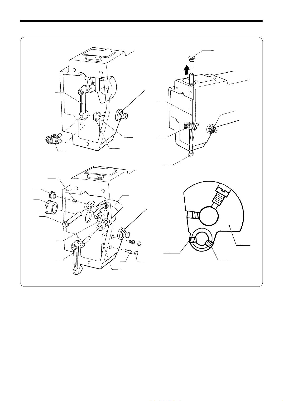
9. Lower shaft mechanism (1)
Chapter 3. Assembly
!4
!3
!3
!3
e
!5
Matching mark
w
!6
r
w
q
!1
!0
u
!2
!7
q
0.05 - 0.12mm
y
o
i
t
u
!1
1. Tilt the machine head until it stops.
2. Insert the rock gear shaft q from the rear of the machine, pass the rock gear w, the set screw collar e over the shaft,
bring them close together without any clearance, and tighten the set screw r.
3. Insert the lower shaft t from the rear of the machine, pass the set screw collar y over it, and engage the lower shaft
gear u with the rock gear w.
4. Sandwich the lower shaft bush i between the lower shaft gear u and the set screw collar y without any clearance,
and tighten the set screw o.
5. Fit the retaining ring !0 on the lower shaft t, press the driver !1 against the retaining ring !0, and tighten the bolt !2.
6. Return the machine head to its original position.
7. Fit the crank rod !3 over the crank of the upper shaft !4, align the matching mark of the crank rod !3 with that of the
upper shaft !4, and tighten the screw !5.
8. Tilt the machine head until it stops.
9. Turn the pulley !6 to move the rock gear w right and left until the pulley rotates easily. Turn the rock gear shaft q to
allow 0.05 - 0.12 mm play of the driver !1. Then tighten the set screw !7.
10.Return the machine head to its original position.
BAS-311E.311EL.326E.326EL
43
Page 52

Chapter 3. Assembly
10. Lower shaft (Rotary hook) (2)
1. Fit the inner rotary hook in the large shuttle hook.
2. Turn the pulley to raise the needle bar from its lowest
t
3. Turn the pulley to align the inner rotary hook point with
ADP × 17
w
DP × 5
q
r
y
e
u
position until the second highest reference line on the
needle bar q aligns with the end of needle bar bush (D)
w. Turn the shuttle driver e so that the inner rotary
hook point is aligned with the center of needle r, then
tighten the bolt t.
the center of the needle. Loosen the set screw y so that
the clearance between the needle r and the inner rotary hook point is 0.01 - 0.08 mm, then rotate the shuttle
hook adjust stud u to adjust.
r
r
0.01 - 0.08mm
r
e
4. Turn the pulley to align the inner rotary hook point with
the center of the needle r.
Loosen the set screw and adjust the shuttle hook adjust
stud i so that the needle r lightly contacts the needle
receiver of the shuttle driver e.
5. Remove the needle r.
i
44
!2
!1
!0
o
6. Attach the large shuttle hook o to the large shuttle hook
body !0.
7. Insert the bobbin !1 into the bobbin case !2, then attach
them to the inner rotary hook !3.
!3
BAS-311E.311EL.326E.326EL
Page 53

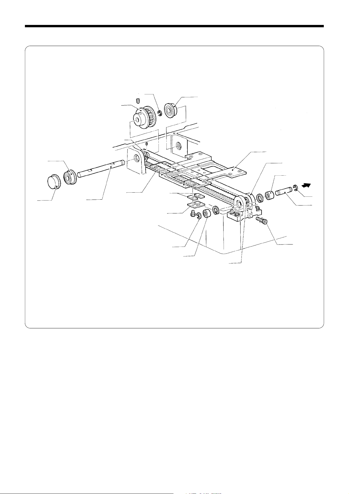
11. Thread trimmer mechanism
Chapter 3. Assembly
r
!2
0.5mm
w
t
e
q
o
y
i
u
e
!4
V notch
A
!0
i
!1
o
1. Fit the hole of the thread trimmer connecting rod q over the pin of the connecting rod lever w. Secure the needle plate
e using the screws r and t so that the hole on the needle plate is centered at the needle position.
2. Turn the pulley y until the mark u has slightly passed over the horizontal line.
(Adjust the position of the pulley to the position where the cam gooves on the thread trimmer cam do not fluctuate.)
3. Attach the thread trimming solenoid i using the screw o. At this time, the plunger !0 of the thread trimming solenoid
i must be fully pressed (the same status as when the thread trimming solenoid i is turned on), and a 0.5 mm
clearance must be provided between the thread trimmer driving lever !1 and the driving lever stopper !2.
4. Make sure that the thread trimmer driving lever !1 moves smoothly when the plunger !0 is pressed and released.
5. Tilt the machine head until it stops.
6. Loosen the nut !3, move the connecting rod lever w to the left and right to align the V notch A of the movable knife !4
with the mark on the needle plate e, and tighten the nut !3.
7. Return the machine head to its original position.
!3
w
BAS-311E.311EL.326E.326EL
45
Page 54

Chapter 3. Assembly
12. Feed guide mechanism (Home position adjustment: X )
311E, 311EL, and 326E
1. Secure the large shuttle hook cover q with the two
shoulder screws w.
2. Secure the needle sub plate e with the screw r.
r
e
t
w
q
i
3. Remove the presser foot t.
4. Remove the screws u, tlat screws o and the work
clamp guide brackets A y, B i and replace the work
clamp !0 with the H-position standard plate !1.
Note: Securely attach the H-position standard plate !1
using the work clamp guide brackets A y, B i
and the flat screws o.
o
u
!2
y
!3
!1
P key
!0
Parallel
X-reference
line
!5
!4
!6
!1
5. Connect the programmer !2 to the operation panel !3.
6. Plug the cord into the wall socket, and turn on the power of the machine.
7. Step on the foot switch to lower the H-position standard plate !1.
8. Press the P key on the programmer !2.
9. Attach the needle !4.
10.Turn the pulley to bring the needle !4 close to the H-position standard plate !1.
11.Press the jog key ( vu ) to adjust the work clamp arm !5 until its X-direction motion is parallel to the X-reference line
of the H-position standard plate !1. Securely tighten the screws !6.
46
BAS-311E.311EL.326E.326EL
Page 55

!1
Chapter 3. Assembly
0.1 - 0.5mm
!4
!8
H - position
(X=0, Y=0)
12.Press the P key and adjust the X-sensor setting plate !7 so that the needle !4 is aligned with the home position (X=0,
Y=0) of the H-position standard plate !1.
13.Press the P key again to make sure that the needle !4 is aligned with the home position (X=0, Y=0) of the H-position
standard plate !1.
14.Secure the X-sensor setting plate !7 using the screw.
15.Remove the needle !4.
16.Press the P key to be out of the program mode, and turn off the power.
17.Replace the H-position standard plate !1 with the work clamp.
Note: When adjusting the X home position, be sure to set the clearance between the X-home position dog !8 and the
surface where the sensor is activated to 0.1 - 0.5 mm. If the clearance is too great, an error in home position
detection may occur because the temperature of the sewing machine rises during sewing operation.
!7
BAS-311E.311EL.326E.326EL
47
Page 56

Chapter 3. Assembly
Feed guide mechanism (Home position adjustment: Y )
311E and 311EL
r
e
q
e
t
w
H - position
(X=0, Y=0)
1. Press the P key on the programmer, and adjust the Y-home position dog e so that the needle q is aligned with the
home position (X=0, Y=0) of the H-position standard plate w.
2. Press the P key again to make sure that the needle q is aligned with the home position (X=0, Y=0) of the H-position
standard plate w.
3. Secure the Y-home position dog e using the set screw r.
4. Remove the needle q.
5. Press the P key to be out of the program mode, and turn off the power.
6. Replace the H-position standard plate w with the work clamp.
Note: When adjusting the Y home position, be sure to set the clearance between the Y-home position dog e and the
surface where the sensor t is activated to 0.1 - 0.5 mm. If the clearance is too great, an error in home position
detection may occur because the temperature of the sewing machine rises during sewing operation.
t
0.1 - 0.5mm
Feed guide mechanism (Home position adjustment: Y )
326E and 326EL
P key
q
w
H - position
(X=0, Y=0)
1. Press the P key on the programmer, and adjust the Y-sensor setting plate e so that the needle q is aligned with the
home position (X=0, Y=0) of the H-position standard plate w.
2. Press the P key again to make sure that the needle q is aligned with the home position (X=0, Y=0) of the H-position
standard plate w.
3. Attach the Y-sensor setting plate e to the Y-home position bracket r using the bolt t.
4. Remove the needle q.
5. Press the P key to be out of the program mode, and turn off the power.
6. Replace the H-position standard plate w with the work clamp.
Note: When adjusting the Y home position, be sure to set the clearance between the Y-driving shaft y and the surface
where the sensor u is activated to 0.1 - 0.5 mm. If the clearance is too great, an error in home position detection
may occur because the temperature of the sewing machine rises during sewing operation.
r
y
t
u
0.1 - 0.5mm
e
48
BAS-311E.311EL.326E.326EL
Page 57

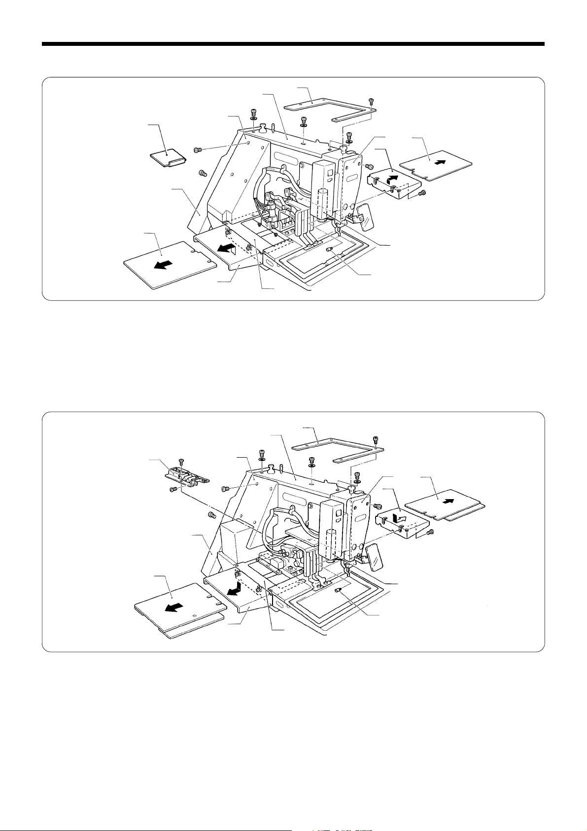
13. Covers 311E
e
q
u
y
t
r
Chapter 3. Assembly
1. Secure XY-feed base covers (L) q and (R) w with the
screws e.
2. Attach Y-feed bracket cover (B) r to Y-feed bracket
cover (A) t.
Secure the right and left X-feed bracket covers (L),(R) y
with the screws u.
y
o
!0 i
!1
!2
u
w
e
3. Attach the thread wiper connecting rod i to the plunger
!0 with the plunger pin o, then secure the face plate !1
with the screw !2.
4. Attach the presser foot !3 and the needle !4 in place and
attach the feed plate !5 to the feed bracket !6 with the
screw.
@2
@1
!3
@0
!4
!5
!7
!6
5. Attach the top cover !7, and the side cover !8 with the
screws.
6. Set the V belt !9 over the pulley @0, then secure belt
cover @1 with the screws @2.
!8
!9
BAS-311E.311EL.326E.326EL
49
Page 58

Chapter 3. Assembly
311EL
t
t
e
u
y
w
i
o
!1
r
!0
q
e
1. Attach the XY-feed bracket covers L q and R w using the screws.
2. Insert the left and right feed bracket cover supports e in the direction of the arrow, and tighten the screws.
3. Attach the X-axis feed bracket covers t using the screws.
4. Attach the faceplate t using the screws.
5. Attach the plunger pin y to the plunger u.
6. Attach the top cover i, the belt cover o, and the frame side cover !0 using the screw.
326E · 326EL
o
t
!0
q
1. Attach the XY-feed bracket covers L q and R w using the screws.
2. Insert the left and right feed bracket cover supports e in the direction of the arrow, and tighten the screws.
3. Attach the X-axis feed bracket covers r using the screws. (Use the front screws.)
4. Attach the bellows assy t to the work clamp arm and the X-axis feed bracket covers r using the screws.
5. Attach the faceplate y using the screws.
6. Attach the plunger pin u to the plunger i.
7. Attach the top cover o, the belt cover !0, and the frame side cover !1 using the screws.
!1
e
r
yw
e
i
u
r
50
BAS-311E.311EL.326E.326EL
Page 59

Chapter 4. Adjustments
1. Adjusting the needle bar height adjustment
q
Chapter 4. Adjustments
w
a(DPx5)
Turn the machine pulley to move the needle bar to the lowest position. Then remove the rubber cap w, loosen the screw
e and then move the needle bar up or down to adjust so that the second reference line from the bottom of the needle
(reference line A) is aligned with the lower edge of the needle bar bush q.
*If using a DP ✕ 5 needle, use the highest reference line (reference line a).
A(DPx17)
e
2. Adjusting the needle bar lift amount
q
b(DPx5)
The tip of rotary hook
B(DPx17)
Needle center
Needle
e
e
w
Turn the machine pulley to raise the needle bar from the lowest position until the lowest reference line on the needle
(reference line B) is aligned with the lower edge of the needle bar bush q. Then loosen the bolt w and move the driver e
to adjust so that the tip of the rotary hook is aligned with the needle center line.
*If using a DP ✕ 5 needle, use the second reference line from the top of the needle (reference line b).
BAS-311E.311EL.326E.326EL
51
Page 60

Chapter 4. Adjustments
3. Adjusting the needle clearance
q
0.01 - 0.08mm
Turn the machine pulley to align the tip of the rotary hook with the needle center line. Then loosen the set screw q and
turn the eccentric shaft w to adjust so that the clearance between the needle and the rotary hook is 0.01 - 0.08 mm.
w
4. Adjusting the driver needle guard
q
w
e
Turn the machine pulley to align the tip of the rotary hook with the needle center line. Then loosen the set screw w and
turn the eccentric shaft e to adjust so that the driver needle guard q contacts the needle. If the needle contact pressure is
too great, skipped stitches may occur. On the other hand, if the driver needle guard q is not touching the needle, the tip of
the inner rotary hook will obstruct the needle, resulting in an excessively high amount of friction.
5. Adjusting the shuttle race thread guide
q
A
Install the shuttle race thread guide q by pushing it in the direction of the arrow so that the needle groove is aligned with
the center of the needle plate hole.
Note:If the shuttle race thread guide is in the wrong position, thread breakages, soiled thread or catching of the thread
may occur.
52
BAS-311E.311EL.326E.326EL
Page 61

Chapter 4. Adjustments
6. Adjusting the two-step work clamp lift amount
¡The maximum work clamp lift amount is 25 ± 1 mm (for solenoid type) or 30 ± 1 mm (for pneumatic type) from the top
of the needle plate.
¡The lift amount for each model is adjusted as shown in the table at the time of shipment.
Lift amount 20mm 20mm
type
Solenoid type Pneumatic type
6-1. Solenoid type
e
20mm
w
q
1. Turn the power switch OFF.
2. Loosen the bolts w of work clamp arm lever F q.
3. Place a scale against the work clamp e, and then move work clamp arm lever F q up or down to adjust so that the
amount of lift above the top of the needle plate is 20 mm.
4. After adjusting the lift amount (20 mm), tighten the bolts w of work clamp arm lever F q.
BAS-311E.311EL.326E.326EL
53
Page 62

Chapter 4. Adjustments
6-2. Pneumatic type
(BAS-311E · 311EL)
q
(BAS-326E · 326EL)
y
y
w
e
w
r
e
e
w
e
20mm
r
t
w
r
r
20mm
1. Turn on the air, and then press the work clamp lifter switch q while turning it clockwise, to raise the work clamp w.
2. Loosen the bolts r of work clamp arm lever F e (BAS-326E, 326EL: work clamplifter lever y).
3. Place a ruler against the work clamp w, and then move work clamp arm lever F e (BAS-326E, 326EL: work clamplifter
lever y) vertically to find the position where the lift amount of the work clamp is 20 mm.
4. After adjusting the lift amount to 20 mm, tighten the bolts r of work clamp arm lever F e(BAS-326E, 326EL: work
clamplifter lever y).
t
6-3. Adjustment of air pressure (for Pneumatic type 311E, 311EL, 326E,
326EL)
1. Air pressure should be 0.49 MPa [5 kgf /cm2].
The air pressure can be adjusted by pulling up and turning the control knob w on the integrator q.
After adjustment is complete, push the control knob w
downward to lock it.
w
e
r
q
2. If water stands in the bottle of the integrator q, turn the
drain cock e in the direction indicated by an arrow to
drain the water.
Note: Open the air cock r slowly.
54
BAS-311E.311EL.326E.326EL
Page 63

Chapter 4. Adjustments
7. Adjusting the movable knife
w
q
Index mark
A
e
r
Loosen the nut e and move connecting rod lever r to the left or right to adjust so that the V section A of the movable
knife q is aligned with the index mark B on the needle plate w when the machine is at the stop position.
7-1. Replacing the movable and fixed knives
i
t
u
w
y
!0
o
1. Remove the bolt t, and the feed plate y, the screws u and i, and the needle plate w. Disconnect the thread cutter
connecting rod o from the connecting lever pin !0.
q
Spacer
!2
!1
!1
2. Remove the movable knife, and replace it with a new
one. Check the cutting edge of the movable knife q and
the fixed knife !1. If necessary, use the provided movable knife spacer (t=0.4,t=0.5,t=0.6) to adjust the knives
so that they cut properly.
BAS-311E.311EL.326E.326EL
0.5mm
3. Install the fixed knife !1 0.5 mm away from the needle
hole plate !2.
55
Page 64

Chapter 4. Adjustments
NOTE:
A. After the movable knife and fixed knife are properly engaged, tighten shoulder screw.
B. Turn the movable knife (in the direction of the arrow) while the shoulder screw is still tightened.
C. Loosen the shoulder screw.
D. Turn the movable knife (in the direction of the arrow) while the shoulder screw is still loosened.
Repeat above steps (A, B, C and D) four of five times to maintain the cutting performance of the knife.
Movable knife
Knives
Knives
Fixed knife
Knives
Knives
q
w
o
u
4. Fit the thread cutter connecting rod o on connecting lever pin !0, and install the needle plate w.
i
* When fitting the connecting rod o on the connecting
lever pin !0 and before tightening the screws u and
i, move the needle plate w back and forth slightly to
confirm that the movable knife q is pulled by the connecting rod o.
!0
56
BAS-311E.311EL.326E.326EL
Page 65

311E, 311EL
y
!3
326E, 326EL
w
t
t
Chapter 4. Adjustments
5. When installing the feed plate y, use a 2 mm- diameter
pin !3 (such as a needle) to align the hole in the needle
plate w with the hole in the feed plate w when the machine is at the home position, and then tighten the bolts
t.
* How to determine the mechanical home position
a. Connect the programmer to the operation panel.
b. Plug the cord into the wall socket, and turn on the
power.
c. Press the P key on the programmer to determine the
mechanical home position.
y
!3
w
BAS-311E.311EL.326E.326EL
57
Page 66

Chapter 4. Adjustments
8. Adjusting the lowest point of the presser foot
1. Turn the pulley to align the needle bar with the shuttle
hook. At this time, turn the stepping work clamp connecting rod q to turn stepping work clamp arm F w in
the direction of the arrow, and move the stepping link
w
o
i
e
y
0.5 - 1mm
assy e in the direction of the arrow. When the presser
foot is at the lowest position, secure the stepping work
clamp connecting rod q to the upper shaft t using the
set screw r.
Adjust the lift stroke of the presser foot to 3 - 5 mm, and
5 - 8 mm. When the clearance between the presser bar
lifter y and the presser bar bush u is 0.5 - 1 mm, tighten
the bolt of stepping work clamp arm F w. (At this time,
the match mark i of stepping work clamp arm F w will
be almost aligned with that of arm mark o.)
Note: Make sure that stepping work clamp arm F w has
no end play.
!6
r
!5
!4
q
u
!1
!0
t
2. Attach the needle to the needle bar.
3. Turn the pulley to insert the needle !2 into the hole of the
presser foot !4. Turn the presser bar !5 so that the
needle !2 is in the center of the hole of the presser foot
!4, and tighten the screw of the needle bar clamp !6.
!2
58
BAS-311E.311EL.326E.326EL
Page 67

8-1. Presser foot adjustment
1. Loosen the screw q, lower the presser foot w so that its
2. Turn the pulley manually to make sure that the needle
r
e
q
w
w
9. Changing the presser foot lift
Standard presser foot q lift is 3 mm (max. 8 mm).
Chapter 4. Adjustments
bottom can lightly touch the workpiece, and tighten the
screw q again.
Note: If the presser foot is lowered too far, the
workpiece will shift when sewing. Also, if the
presser foot is too high, skipped stitches may occur.
enters the center of the needle hole in the presser foot
w. If the needle is not aligned with the center of the
needle hole, remove the cap e, loosen the screw r, and
turn the presser foot (presser bar) for adjustment.
When the presser foot is in the high position and the
needle point is projecting below the presser foot, it
could cause injuries.
o
q
e
t
i
3 - 5mm
w
r
Adjusting presser foot lift to 3 - 5 mm
1. Loosen the shoulder screw w and open the stepping cover e.
2. Loosen the nut r and adjust the stepping work clamp con. rod t pisition.
(When the stepping work clamp con. rod t is raised, the lift will amount increase. When lowered, the lift amount will
decrease.)
Adjusting presser foot lift to 5 - 8 mm
1. Turn the upper shaft to set the presser foot to its lowest point. Loosen the bolt o of stepping work clamp arm R i.
Adjust the clearance between the presser lifter y and the presser bar bush u to 0.5 - 1 mm.
2. Loosen the nut r and adjust the stepping work clamp con. rod t position.
(When the stepping work clamp con. rod t is raised, the lift amount will increase. When lowered, the lift amount will
decrease.
!4
!3
!1
If vertical movement of the presser foot is not required
1. Remove the face plate !0.
2. Remove the shoulder screw !1 and re-attach the stepping link !2 to the upper screw hole !4 of stepping work
clamp arm F !3.
u
y
0.5 - 1mm
!2
!0
BAS-311E.311EL.326E.326EL
59
Page 68

Chapter 4. Adjustments
10. Wiper adjustment
■ For vertical wiper (standard)
t
r
q
112mm
e
w
approximately 2 mm
w
t
y
15mm
1. When the thread wiper solenoid plunger q is driven to the full stroke, the wiper w should be 15 mm in front of the
needle center. Loosen bolts e and shift the entire solenoid bracket r up or down to adjust.
The standard height from the solenoid setting plate r bottom to the needle plate top is approximately 112 mm.
2. When the wiper w is operated and aligned with the center of the needle bar, the distance from the wiper w to the point
of the needle should be approximately 2 mm. Loose the screw t and move the wiper w in or out to adjust. As shown
in Fig. A, make sure the wiper w does not strike the presser foot y or the needle.
Note: Make that the wiper w is not touching the finger guard.
■ For horizontal wiper (optional)
e
y
r
t
q
w
15 - 16mm
(35mm)
(25mm)
(25mm)
1. Loosen the set screw e and move the wiper arm support r up or down to adjust so that there is a clearance of 15 - 16
mm between the bottom of the thread wiper q and the needle plate w when the thread wiper q is aligned with the
center of the needle bar.
2. After the thread wiper has wiped the thread, loosen the bolt t and move the solenoid setting plate y up or down to
adjust the distance to approximately 35 mm.
(35mm)
60
BAS-311E.311EL.326E.326EL
Page 69

11. Adjusting the home position
■ (X axis)
1. Remove the needle and presser foot.
2. Remove the flat screws w and screws r of the work
q
r
Chapter 4. Adjustments
clamp guide brackets A q, B e and replace the work
clamp y with the H-position standard plate t.
Note: Attach the H-position standard plate t using the
work clamp guide brackets A q, B e and the flat
screws w.
w
e
t
y
!1
0.1 - 0.5mm
o
u
y
H - position
(X = 0, Y = 0)
3. Press the P key and adjust the X-sensor setting plate i so that the needle u is aligned with the home position (X=0,
Y=0) of the H-position standard plate t.
4. Press the P key again to make sure that the needle u is aligned with the home position (X=0, Y=0) of the H-position
standard plate t.
5. Secure the X-sensor setting plate i using the screws o.
6. Remove the needle u.
7. Press the P key to be out of the program mode, and turn off the power.
8. Replace the H-position standard plate t with the work clamp.
Note: When adjusting the X home position, be sure to set the clearance between the X-home position dog !0 and the
surface where the sensor !1 is activated to 0.1 - 0.5 mm. If the clearance is too great, an error in home position
detection may occur because the temperature of the sewing machine rises during sewing operation.
!0
i
BAS-311E.311EL.326E.326EL
61
Page 70

Chapter 4. Adjustments
■ (Y axis) 311E and 311EL
q
1. Remove the belt cover q and the frame side cover w.
2. Connect the programmer to the operation panel.
3. Turn on the power of the machine.
4. Press the P key on the programmer.
w
5. Attach the needle e.
6. Turn the pulley to approach the needle e to the H-position standard plate r.
e
r
e
t
y
u
t
r
0.1 - 0.5mm
u
H - position
(X = 0, Y = 0)
7. Press the P key and adjust the Y-home position dog t so that the needle e is aligned with the home position (X=0, Y=0)
of the H-position standard plate r.
8. Press the P key again to make sure that the needle e is aligned with the home position (X=0, Y=0) of the H-position
standard plate r.
9. Secure the Y-home position dog t using the set screw y.
10.Remove the needle e.
11.Press the P key to be out of the program mode, and turn off the power.
12.Replace the H-position standard plate r with the work clamp.
Note: When adjusting the Y home position, be sure to set the clearance between the Y-home position dog t and the
surface where the sensor u is activated to 0.1 - 0.5 mm. If the clearance is too great, an error in home position
detection may occur because the temperature of the sewing machine rises during sewing operation.
62
BAS-311E.311EL.326E.326EL
Page 71

■ (Y axis) 326E, 326EL
Chapter 4. Adjustments
y
u
q
0.1 - 0.5mm
w
H - position
(X = 0, Y = 0)
1. Press the P key and adjust the Y-sensor setting plate e so that the needle q is aligned with the home position (X=0,
Y=0) of the H-position standard plate w.
2. Press the P key again to make sure that the needle q is aligned with the home position (X=0, Y=0) of the H-position
standard plate w.
3. Attach the Y-sensor setting plate e to the Y-home position bracket r using the bolt t.
4. Remove the needle q.
5. Press the P key to be out of the program mode, and turn off the power.
6. Replace the H-position standard plate w with the work clamp.
Note: When adjusting the Y home position, be sure to set the clearance between the Y-driving shaft y and the surface
where the sensor u is activated to 0.1 - 0.5 mm. If the clearance is too great, an error in home position detection
may occur because the temperature of the sewing machine rises during sewing operation.
r
t
e
BAS-311E.311EL.326E.326EL
63
Page 72

Chapter 4. Adjustments
12. Adjusting the tension of the timing belt
Note: Be sure to check the home position after adjusting the tension of the timing belt.
■ Adjusting the tension of X-timing belt 311E
1. Remove the X-feed bracket cover q.
2. Loosen the bolt e of X-pulley base B w, then adjust the
q
e
tension using the bolt r.
9.8N(1kgf)
q
t
w
80mm
r
3. Move the X-feed bracket y to the left end and apply a
load of 9.8N (1 kgf) to the center of the X-timing belt B t.
Then adjust the X-timing belt B t with the adjust bolt u
to produce a deflection of 3 mm.
y
3mm
u
■ Adjusting the tension of Y-timing belt
1. Remove the belt cover q and the frame side cover w.
64
r
t
e
q
w
2. Loosen the bolt r, and move the Y-feed pulse motor
bracket e to adjust the tension of the Y-timing belt.
3. When the power of the machine is turned off, there
should be no slack in the Y-timing belt y and the work
clamp arm u should move back and forth easily.
Adjust the position of the Y-feed pulse motor bracket e
using the bolt t.
u
BAS-311E.311EL.326E.326EL
When the power is turned on, move the work clamp arm
u back and forth, and adjust the tension of the Y-timing
belt y using the bolt t so that there is no looseness in
the work clamp arm u.
Page 73

311EL and 326E, 326EL
•311EL
1.5mm
•326E, 326EL
w
t
y
1mm
9.8N
(1kgf)
e
9.8N
(1kgf)
•311EL
3mm
•326E, 326EL
2.5mm
Chapter 4. Adjustments
!1
o
!2
q
i
u
r
!0
■ Adjusting the tension of X-timing belt A326
X-timing belt A326 e is looped around X-timing pulley A311 (A326) q and X-timing pulley B326 w.
The tension of X-timing belt A326 e should have 1 mm deflection when it is pressed in the middle of X-timing pulley
A311 (A326) q and X-timing pulley B326 w with a load of 4.9N (0.5 kgf) in the direction of the arrow.
Turn the bolts r clockwise to move X-pulley bracket L t until the appropriate tension is given, and secure X-pulley
bracket L t to the bed using the screws y.
Note: The bolts r for adjusting the timing belt tension are in front of and behind X-pulley bracket L t. Adjust the bolts
r equally so that X-pulley bracket L t does not lean to one side.
■ Adjusting the tension of X-timing belt B326
X-timing belt B326 o is looped around timing pulley A u and timing pulley B i.
The tension of X-timing belt B326 o should have 3 mm deflection when it is pressed in the middle of timing pulley A u
and timing pulley B i with a load of 9.8N (1 kgf) in the direction of the arrow. (326EL: 2.5 mm deflection with a load of
9.8N (1 kgf)
Turn the bolts !0 clockwise to move X-pulley bracket R !1 until the appropriate tension is given, and secure X-pulley
bracket R !1 to the bed using the bolts !2.
BAS-311E.311EL.326E.326EL
65
Page 74

Chapter 4. Adjustments
13. Adjusting backlashes
q
w
0.05 - 0.12mm
q
■ Lower shaft
1. Tilt the machine head until it stops.
2. Loosen the set screw q, then turn the rock gear shaft w
to provide 0.05 - 0.12 mm looseness at the tip of the
shuttle driver e.
e
■ Y-axis feed
Loosen the four bolts q, then adjust the Y-pulse motor
w so that there is no backlash between the rock gear and
the idle gear.
w
66
BAS-311E.311EL.326E.326EL
Page 75

14. Adjusting the driving lever stopper position
q
w
6mm
Chapter 4. Adjustments
6mm
t
e
e
Most 0.15 mm
r
r
1. Remove the screws q and the top cover w.
2. If thread trimming is not performed, loosen the bolts t so that the difference between the thread trimmer driving lever
e and the driving lever stopper r is 6 mm.
* Make sure that the clearance between the thread trimmer driving lever e and the driving lever stopper r is at the
most 0.15 mm.
The driving lever stopper r has an imprinted number mark: 2, 3, or 4. If the clearance is larger than 0.15 mm, replace
the driving lever stopper 4 with that with a different number. For example, when the number 3 stopper is used,
replace it with number 4 stopper. When the number 4 stopper is used, replace it with number 2 stopper.
15. Adjusting the thread trimmer driving lever position
q
w
y
t
r
e
1. Remove the screws q and the top cover w.
2. Turn the pulley to place the thread trimmer cam e with its non-operating portion facing upward.
3. Loosen the nut t. Move the screw y so that the roller r of the thread trimmer driving lever will return smoothly when
it is put into the groove of the thread trimmer cam e.
BAS-311E.311EL.326E.326EL
67
Page 76

Chapter 4. Adjustments
16. Work clamp lift components for manual operation (Sole-
noid type)
q
w
1. Fully press in the plunger w of the work clamp solenoid
q.
Lightly make the shaft touch here.
y
t
2. Adjust the presser bar lifter lever arm y so that the shaft
of the shoulder screw lightly touches the rod t when
the presser bar lifter lever e is in contact with the stopper r.
r
e
u
17. Adjusting the presser foot height
1. Turn the pulley to where the needle is at its lowest posi-
w
r
tion. The lowest point of the presser bar q is at the
place where the needle is aligned with the shuttle hook.
2. Fully turn the plunger of the stepping solenoid w in the
direction of the arrow, then adjust the lifter lever t so
that the work clamp lifter lever e is in contact with the
clamp needle bar r.
68
y
e
q
18mm
t
3. Measure the dimension between the presser foot y and
the needle plate when the presser foot is at the lowest
position.
Turn the pulley to set the needle bar at its lowest position. When pulling the lifter lever t toward you until it
makes contact with the adjust screw u, the distance between the presser foot and the needle plate should be 18
mm. Loosen the nut i, and adjust the adjust screw u.
i
u
t
BAS-311E.311EL.326E.326EL
Page 77

18. Adjusting the needle up stop position
e
Chapter 4. Adjustments
Feed plate in operation
Material
r
w
u
q
t
y
Feed plate not in operation
1. Loosen the screw t (at the U side on the pulley q), and turn the pulley q so that the mark w on the pulley is inside the
mark r of the belt cover e .
The pulley q stops later if it is turned clockwise; it stops earlier if it is turned counterclockwise.
The standerd needle up stop position is 6 mm below the needle bar dead point.
2. Timing between the needle and the feed mechanism is adjusted so that the feed mechanism srarts operating after the
needle comes out of the material sewn, and stops before the needle penetrates the material.
The screw y on the D side is tightened fully counterclockwise at the time of shipment.
3. The screw u cannot be adjusted because it is used for detecting the needle stop position.
BAS-311E.311EL.326E.326EL
69
Page 78

Chapter 5. How to make up the work clamp
Chapter 5. How to make up the work clamp
• The work clamp is available in two types; clamping type and cassette type.
The maximum sewing range is (W × L) BAS-311E (130mm × 60mm), 311EL (220mm × 60mm), 326E (200mm × 100mm),
326EL (220mm × 100mm).
■ Clamping type ■ Cassette type
Work clamp
(separate
plate)
Work clamp
(single type)
Cassette clamp
Cassette support
Feed plate
1. How to make up clamping type work clamp
■ How to make up the work clamp
Cut out the work clamp blank so that the cutout size is
wider than the sewing position by (half of the presser
Work clamp
(Single type work
clamp blank)
Sewing position
(The needle threads
along)
foot diameter + 1 to 1.5 mm).
D: diameter of the top end of the presser foot
Cassette clamp
assembly
Feed plate
(Feed plate blank)
D
D/2 + 1 to 1.5mm
D/2 + 1 to 1.5mm
Work clampPresser foot
1 - 1.5mm
■ How to make up the feed plate
Cut out the feed plate blank 1 to 1.5 mm apart from the
sewing position.
In the case of the left figure, 1 to 1.5 mm margin is required on both sides of the sewing position.
Feed plate
Sewing position
1 - 1.5mm
1 - 1.5mm
70
1 - 1.5mm
1 - 1.5mm
BAS-311E.311EL.326E.326EL
Page 79

Chapter 5. How to make up the work clamp
■ How to make up the plastic work clamp
1. Cut out the plastic plate according to the counter of a
material to be sewn.
Work clamp
(Standard)
2. Bond a paper cushion material or the like around the cutout section to firmly press a material to be sewn.
3. Make up the feed plate by referring to item 2.
"How to make up the feed plate".
OT pesser plate
assembly
(plastic plate)
Feed plate
2. How to make up cassette type work clamp
The cassette type work clamp is composed of cassette plate
(U), cassette plate (D), and the hinges as illustrated in the
left figure.
Cassette clamp
assembly
Hinges
Cassette plate
D-B
Cassette plate
D-B
Cassette plate D-A (iron)
Cassette plate D-B
1. Cut out cassette plates (U) and (D). For cutting dimensions, refer to section "How to make up the clamping
type work clamp".
* Making up two cassettes to use them alternately will
increase work efficiency.
2. Bond a paper cushion material or the like around the cutout section to firmly press a material to be sewn.
Cassette plate (D) is available in two types; D-A and D-B.
* Use cassette D-B with the same way as D-A, except
that a plastic plate or the like must be bonded on the
back of D-B. When mounting hinges on cassette plate
D-B, insert a countersunk screw M3 into the 4.6 mm
diameter countersunk hole prior to bonding the plastic
plate.
Lower cassette plate
(plastic)
BAS-311E.311EL.326E.326EL
71
Page 80

Chapter 5. How to make up the work clamp
Cassette presser
117.5
Cassette presser 1R
Cassette presser 1L
70 82
t=3.2
SO2845-001
SO2846-001
141.5
106
Cassette presser 2R
Cassette presser 2L
70
82
t=3.2
118
SO2847-001
SO2848-001
70
Cassette presser 3R
Cassette presser 3L
Clamp spring
(52)
40
Cassette presser 4R
Cassette presser 4L
70
82
t=3.2
SO2851-001
SO2852-001
25
t=0.4
40
t=0.6
SO2853-001Clamp spring 1
SO2854-001Clamp spring 2
Note: To use the cassette support the set base for feed plate illustrated below should be attached.
(82)
70
82
SO2849-001
t=3.2
SO2850-001
60
t=0.8
SO2855-001Clamp spring 3
Set base for feed plate
S12586-001
Cassette holder plate designed
for the model BAS310
Cassette holder plate
S13006-001
S44411-001
Hinge, left
152633-001
Cassette holder plate
S02963-201
Cassette holder plate (t=3.2)
S02963-201
Pin
S13007-001
Nut
021660-306
Cassette plate U-A (t=1) S02968-001
Cassette lower plate
A (t=1) S02969-000
B (t=2) S02970-000
A - 180 (t=1) S14386-000
B - 180 (t=2) S14387-000
B (t=2) S02971-000
A - 180 (t=1) S14389-000
B - 180 (t=2) S14390-000
Hinge, right
152632-001
Cassette plate D-B (t=1)
S02967-101
Cassette plate D-B 180 (t=1)
S02967-001
Cassette presser (A) assembly
Cassette plate U-A
Hinge,left
Hinge,right
Cassette plate D-A
S02959-101
S02968-000
152633-001
152632-001
S02966-101
72
Cassette plate D-A (t=1)
S02966-101
Cassette plate D-A 180 (t=1)
S14392-201
BAS-311E.311EL.326E.326EL
Cassette presser (B) assembly
Cassette plate U-A
Hinge,left
Hinge,right
Cassette plate D-A
S02960-101
S02971-000
152633-001
152632-001
S02966-101
Page 81

Chapter 6 Power supply and electrical parts adjustment
Chapter 6 Power supply and electrical parts
adjustment
1. Precautions at the time of adjustment
Pay attention to the following when opening the control box for maintenance.
■ Electric shock
Some large capacitors may have a high voltage remaining in them for up to 5 minutes after the power is turned off. To
prevent electric shock, wait at least 5 minutes after the power is turned off before doing the following:
• Opening and closing the control box
• Replacing fuses
• Separating and joining connectors
• measuring resistance
• Doing anything with a possibility of touching something inside the control box
Some adjustments require measuring the voltage while the power is turned on with the control box kept open.
In such a case, be careful not to touch any place other than that for the measurement. In addition, always keep in mind
that a high voltage remains for 5 minutes after the power is turned off.
■ Injury
While the power is turned on, the cooling fan of the control box operates; be careful not to get caught in it.
When separating or rejoining connectors, and measuring something, be careful not to cut your fingers on metal parts
such as heatsinks and covers.
2. Components inside the control box
The following are brief explanations of components inside the control box. See control circuit block diagram at the end of
this manual for the details of the connections.
■ Main PCB
The main PCB is fixed to the rear panel of the control box. This PCB serves to control machine operation.
■ Power supply circuit board
The power supply circuit board is fixed at the bottom of the control box. Four fuses are mounted on this PCB.
■ Panel circuit board
The panel circuit board is fixed to the front panel of the control box. This PCB controls indications of the machine status
and the input operation.
■ DC fan motor
The DC fan motor serves as a fan to cool the inside of the control box. Clean the inlet filter monthly.
■ Conversion transformer (depending on power supply voltage specification)
The conversion transformer controls the power supply voltage to provide 220 V.
Operation panel Control box
Panel circuit board
Conversion transformer
Inlee fileer
3.5 FDD
Main PCB
BAS-311E.311EL.326E.326EL
DC fan
Power supply
circuit board
73
Page 82

Chapter 6 Power supply and electrical parts adjustment
3. Fuse explanation
When replacing a fuse, follow the instructions indicated in "10-9. Troubleshooting flowchart."
If a component on a PCB is damaged, a fuse may blow again immediately even when it has been replaced.
When replacing a fuse, be sure to use the specified ones listed below.
No.
1
(quick melting type, 5A-250V)
2
(quick melting type, 5A-250V)
3
4
(glass tube fuse, 6A-250V)
(glass tube fuse, 6A-250V)
Fuse No.3
Part name
G fuse (5AFB)
G fuse (5AFB)
Fuse 6A
Fuse 6A
Part code
S08030-000
S08030-000
153242-000
153242-000
Manufacturer
Toyo Fuse
Company
TOYO5A
Toyo Fuse
Company
TOYO5A
Fuji Tanshi
Company FGBO
Fuji Tanshi
Company FGBO
When a fuse has blown
•The feed mechanism and work clamp do
not operate.
•Error [E-A1] appears.
•The machine motor does not turn.
•Error [E-20] appears.
The power lamp is not lit, and nothing
operates.
The power lamp is not lit, and nothing
operates.
Fuse No.1
Fuse No.2
Fuse No.4
74
BAS-311E.311EL.326E.326EL
Page 83

Chapter 6 Power supply and electrical parts adjustment
4. Connectors
Most of the machine trouble is due to connector problems including improper connection or insufficient contact. Therefore, be sure to check if each connector is correctly inserted and that there is no contact failure between pins and wires
before starting toubleshooting procedures.
■ Connector positions
Outside of the control box
Panel cord connector
Foot switch connector
Main PCB
Main P-ROM(MN)
Motor P-ROM
(MT)
P8
P17
P9
P18
P19
P20
P24(OPTION)
P21
P4
P3
P1
P2
P25
P10
P11
P16
P12
P13
P14P15
P7
BAS-311E.311EL.326E.326EL
P6
P5
75
Page 84

Chapter 6 Power supply and electrical parts adjustment
Power supply circuit board
P5
DC300
P4
ACIN
P3
DC18
Outside of the panel
P1
POWER
P2 PER
Panel circuit board
P4
OPTION 2
P3
OPTION 1
P2
PGM
P5
DRV
Programmer cord
Panel P-ROM
(PL)
P1 FDD
76
BAS-311E.311EL.326E.326EL
Page 85

Programmer and programmer circuit board
Chapter 6 Power supply and electrical parts adjustment
LCD inverter
LCD
Programmer P - ROM
Programmer PCB
Operation panel
LCD contrast VR
BAS-311E.311EL.326E.326EL
77
Page 86

Chapter 6 Power supply and electrical parts adjustment
■ Contact failure
• The connectors functions are divided into four categories. Some connectors may belong to more than one group. Be
sure to investigate another category if a problem is not found in one category.
• Ffor the details of connections, refer to the control circuit block diagram at the end of this manual.
1. Feed mechanism
Problem
• Home position is not properly detected.
• Error [E.A1] appears.
• Forward feed does not operate correctly.
• Error [E.A1] appears.
• Sideways feed does not operate correctly.
• Error [E.A1] appears.
Connector No. and position
Main PCB
X home
Y home
position
position
sensor
sensor
Main PCB
Y pulse motor
Main PCB
2. Work clamp lifter and thread trimmer mechanisms
• The work clamp does not operate.
• The machine does not operate.
• The work clamp does not operate. BAS-311E (Solenoid type)
• Thread trimming is not performed.
• Thread wiper does not operate.
• The work clamp does not oeprate.
Wiper
solenoid
X pulse motor
Main PCB
Foot switch
Main PCB
Thread
trimming
solenoid
Sewing
clamp
solenoid
Control
box
Presser
foot
solenoid
78
BAS-311E.311EL.326E.326EL
Page 87

Chapter 6 Power supply and electrical parts adjustment
• The work clamp does not operate.
• (For BAS-311E solenoid type, there is no need to carry out wiring to
air valves.)
3. Sewing operation
• The power lamp is not lit, and nothing operates.
• Machine operation is unstable.
• The power lamp is not lit, and nothing operates.
• Machine operation is unstable.
• The feed mechanism does not operate.
• The work clamp and the presser foot do not operate.
• Error [E.A1] appears.
Main PCB
Air valve
Power supply circuit board
Conversion transformer
Power switch
Power supply circuit board
• The machine motor does not run.
• Motor operation is unstable.
• Needle up stop position is not correct.
• Error [E.20] appears.
• Error [E.22] appears.
• The machine motor does not run.
• Motor operation is unstable.
• Needle up stop position is not correct.
• Error [E.20] appears.
• Error [E.22] appears.
• The machine motor does not run.
• Motor operation is unstable.
• Needle up stop position is not correct.
• Error [E.20] appears.
• Error [E.22] appears.
Main PDB
Power supply circuit board
Main PDB
Power supply circuit board
Main PDB
Main PCB
Synchronizer
BAS-311E.311EL.326E.326EL
79
Page 88

Chapter 6 Power supply and electrical parts adjustment
• The machine motor does not run.
• Motor operation is unstable.
• Needle up stop position is not correct.
• Error [E.20] appears.
• Error [E.22] appears.
4. Programmer operation
• The programmer does not operate.
• No switches on operation panel operate.
• Keys on the programmer respond, but nothing appears on the
display. (P1-LCD)
• Display of the programmer is not lit. (Inverter for P3-LCD)
Main PCB
Machine motor
Ponel circuit board
Programmer circuit board
Programmer circuit board
5. Others
• The DC fan motor does not run.
• Error [E.c5] appears. (P10 FAN-R)
• Error [E.c1] appears. (P10 FAN-L)
• Error [E.F1] appears.
LCD inverter
Main PCB
DC fan
Power supply circuit board
Main PDB
DC fan
• Indication is strange.
• Any switch does not have any effect.
• The power lamp is not lit.
80
BAS-311E.311EL.326E.326EL
Main PCB
Ponel circuit board
Page 89

Chapter 6 Power supply and electrical parts adjustment
• Error [E.12] appears.
• Emergency stop switch is rejected.
• Error [E.40] appears.
Main PCB
EM switch
Ponel circuit board
Floppy disk
BAS-311E.311EL.326E.326EL
81
Page 90

Chapter 6 Power supply and electrical parts adjustment
5. DIP switches
Note: When changing DIP switch setting the power must be off.
Panel DIP switch functions
■ DIP switch A
SW No.
A - 1
• Various setting combinations for DIP switches No.2, No.3 and No.4 can be used to change the way the work clamp is
raised and lowered.
• For pneumatic work clamps, the operation mode can be changed using the two-stage work clamp switch.
SW A-2
------
ON
------
ON
------
ON
------
ON
SW A-3
------
------
ON
ON
------
------
ON
ON
SW A-4
------
------
------
------
ON
ON
ON
ON
After sewing is complete, the work clamp is raised by the operator
and does not rise automatically.
Typ e
Solenoid
Solenoid
Pneumatic
Pneumatic
Pneumatic
Pneumatic
Pneumatic
Pneumatic
Work clamp and presser foot rise and lower simultaneously.
Only work clamp rises and lowers; presser foot lowers
For split-type work clamp the left/right order changes alternately.
Pneumatic Only work clamp rises and lowers; presser foot lowers
ON Pneumatic Work clamp and presser foot rise
Right work clamp, left work clamp and presser foot lower in this order.
Left work clamp, right work clamp and presser foot lower in this order.
Both left and right work clamps, and presser foot lower in this order.
When ON
Function of work clamp pedal
when starting switch is pressed.
when starting switch is pressed.
and lower simultaneously.
They rise in the reverse order.
They rise in the reverse order.
They rise in the reverse order.
82
BAS-311E.311EL.326E.326EL
Page 91

Chapter 6 Power supply and electrical parts adjustment
SW No.
A-5
A-6
A-7
A-8
Single-pedal operation using the starting switch; when the starting switch is pressed, the work clamp
■ DIP switch B
SW No.
B-1
B-2
B-3
B-4
When ON
After sewing is completed, work clamp does not automatically rise (only in split mode).
Clamping force output is produced (Inner clamping device available as an option).
lowers, and when it is released, sewing starts.
Thread breakage detector device is activated (available as an option).
When ON
Single split mode activated
----------------
Thread is not trimmed after an emergency stop.
Needle cooler output is produced. (available as an option).
B-5
B-6
B-7
B-8
When a rotating-type thread breakage detector device is used,
detection precision is changed from 8 to 14.
When a fiber-type thread breakage detector device is used, detection precision is changed from 5 to 10.
Fiber-type thread breakage detector device is ON, and DIP switch A-8 is ON (available as an option)
When using a 3-stage pedal
Feeding speed is switched to high speed.
BAS-311E.311EL.326E.326EL
83
Page 92

Chapter 6 Power supply and electrical parts adjustment
DIP switches inside the control box
DANGER
Wait at least 5 minutes after turning off the power switch and disconnecting the power cord from
the wall outlet before opening the face plate of the control box. Touching areas where high voltages are present can result in severe injury.
■ DIP switch C
c-1
−
ON
−
ON
−
ON
−
ON
SW No.
c-4
c-5
c-2
−
−
ON
ON
−
−
ON
ON
5 For pneumatic type, set to ON when the connection has been changed so that the work clamp remains
c-3
−
−
−
−
ON
ON
ON
ON
Main PCB
Model
−
BAS311E
BAS326EL
−
−
−
−
BAS311EL
Area (X, Y)
−
130×60
220×100
−
−
−
−
220×60
When ON
Controlled sewing area becomes 1200 mm × 400 mm
raised when the power is turned off.
84
c-6
c-7
c-8
Stepping work clamp operated by air pressure is used (when solenoid type is standard).
----------------
----------------
BAS-311E.311EL.326E.326EL
Page 93

■ DIP switch D
Chapter 6 Power supply and electrical parts adjustment
SW No.
D-1
D-2
D-3
D-4
D-5
D-6
D-7
D-8
When ON
The first two stitches at the sewing start will be sewn at low speed (approx. 260 spm).
The last two stitches at the sewing end will be sewn at low speed (approx. 260 spm).
----------------
The last two stitches at the sewing end will be sewn at low speed (approx. 700 spm).
----------------
Slow-speed sewing at the sewing start will be canceled.
When the upper shaft is stopped, the motor will change direction and the needle bar will return to the
vicinity of the needle up stop position.
During an emergency stop, the thread is trimmed and the needle bar stops in the raised position.
BAS-311E.311EL.326E.326EL
85
Page 94

Chapter 6 Power supply and electrical parts adjustment
6. Changing special functions using the memory switches
The functions of the switches on the operation panel can be changed to carry out special functions.
Note:The following are special uses. All the memory switches are set to OFF before shipment from the factory.
t
BAS-300E series
プログラプログラムNO.NO.
PROGRAM NO.PROGRAM NO.
横倍率
e
r
読/書
R / W
1. Turn on the power switch.
2. While pressing the TEST switch q, press the STEP BACK switch w to switch to setting mode.
3. Press the program select switch r so that the number displayed on the display screen e matches the switch number
(00 - 3F) for the function that you would like to select from the table.
4. Press the STEP BACK switch w to switch the setting appearing in the display screen t from OFF to ON.
X-SCALE
縦倍率
Y-SCALE
スピード
SPEED
下糸カウンター
B.T. COUNTER
スプリットNO.
SPLIT NO.
メニューメニュー
MENUMENU
下糸設定下糸設定
B
.
T. SET. SET
テストテスト
TESTTEST
q
電源
POWER
下糸交換下糸交換
B.B.T. CHANGE. CHANGE
y
ステッテップバック
STEP BACKSTEP BACK
w
If pressed once more:
■ If the B.T. CHANGE switch y is pressed at this time, all memory switch settings will be changed to OFF.
5. Press the TEST switch q. The display will return to normal.
86
BAS-311E.311EL.326E.326EL
Page 95

■ Memory Switches (00 – 0F)
Chapter 6 Power supply and electrical parts adjustment
SW No.
memo-00
memo-01
memo-02
memo-03
memo-04
memo-05
memo-06
memo-07
memo-08
When ON
When moving to the home position, the feed plate moves in the order X → Y and the start position
moves in the order Y → X.
When moving to the home position, the feed plate moves in the order Y → X and the start position
moves in the order X → Y.
The forward position becomes the home position, and movement is in the order Y → X and X → Y.
Used for attaching buttons.
Automatic ejector operates. (It is available by special order.)
DIP switch A-7 is set to ON. Cassette is held by automatic ejector and the sewing machine
automatically starts.
Needle stops in up position during emergency stop: (Needle normally stops in down position.)
When sewing is finished, the feed plate moves via the machine home position to the start position.
After the final stitch, the work clamp rises and then the feed plate returns to the start position.
Intermittent work clamp is not used (does not rise).
When using an alternating clamping presser (1/4 ON, 3/4 OFF), and when sewing overlapping
rectangles.
memo-09
memo-0A
memo-0b
memo-0c
memo-0d
memo-0E
memo-0F
After sewing is finished, the work clamp automatically opens and closes once (practice operation)
Wiper is changed to pneumatic wiper. (Pneumatic wiper is available as an option.)
ON when a two-stage tensioner is used. (Two-stage tensioner is available as an option.)
Single-pedal operation by means of two-stage work clamp switches. DIP switch A-2 is ON
Clearing the emergency stop switch action is carried out using the STEP BACK switch.
Test feeding is carried out at the same speed as normal sewing. (For checking feed operation)
■ Memory Switches (20 – 2F)
SW No.
memo-20
memo-21
During feed test operation, feeding 100 stitches at a time is possible using the STEP BACK
After the home position is detected and the machine moves to the sewing start position, the
Jog feeding becomes faster during programming.
When ON
ç
switch.
ç
work clamp rises automatically.
memo-22
memo-23
Note:C indicates that these functions are available for software versions MN-C or later.
When extended option output No.1 is ON, the sewing machine starts automatically.
Set to ON when the bobbin changer is being used. (This part is available by special order.)
BAS-311E.311EL.326E.326EL
ç
ç
87
Page 96

Chapter 6 Power supply and electrical parts adjustment
■ Memory Switches (10 – 1F)
SW No.
memo-10
memo-11
memo-12
memo-13
memo-14
memo-15
memo-16
When ON
Milling device can be used (available as an option).
Bobbin thread counter and production counter operate every time thread is trimmed.
Work clamp is lowered by pressing work clamp first stage switch twice, without using work clamp
second stage switch. When DIP switch A-2 is set to ON, right work clamp and left one are lowered
in this order; when OFF, left work clamp and right one are lowered in this order. They are raised
simultaneously.
When the work clamp is lowered, pressing the start switch causes locking; if the switch is released
before locking, the work clamp is raised. When DIP switch A-2 is set to ON, the right work clamp
and the left one are lowered in this order; when OFF, the right work clamp and the left one are
lowered in this order. They are raised in the reverse order.
Needle up error is detected.
ON when machine is equipped with signal tower indicator.
(This indicator is available by special order.)
ON when machine is equipped with thread nipper. (Thread nipper is available by special order.)
After presser foot rises, thread nipper will operate.
memo-17
memo-18
memo-19
memo-1A
memo-1b
memo-1c
memo-1d
memo-1E
memo-1F
ON when machine is equipped with reset switch. (Reset switch is available by special order.)
When the start switch is pressed, the right work clamp and the left one are lowered in this order,
and sewing starts. When the work clamp first stage switch is pressed, the left work clamp and
right one are lowered in this order (when DIP switch A-2 is set to ON). When DIP switch A-2 is set
to OFF, the order is reversed.
Produces three work clamp signal outputs (right and left work clamps, and presser foot) so that a
two-position air valve can be used. (Two-position air valve is available by special order.)
When using a triple pedal (DIP switch B-7 is also ON), the right is used exclusively to detect the
home position. If DIP switch A-7 is OFF, the left pedal causes left and right work clamps to be
raised and lowered simultaneously. If ON, the left pedal causes the left work clamp to be raised
and lowered, and the starting pedal causes the right work clamp to be lowered.
B430E single foot pedal can be used. DIP switch A-7 should be ON.
Bobbin thread counter is decremented at the start of sewing.
An air pressure drop detection switch is used. (This detection switch is available by special order.)
Split number is changed automatically.
Program number is changed automatically.
88
BAS-311E.311EL.326E.326EL
Page 97

Chapter 6 Power supply and electrical parts adjustment
■ Turn the dial while pressing the STEP BACK switch to change the values.
Turn the dial while pressing the STEP BACK switch to change the values.
SW No.
memo-30
memo-31
memo-32
memo-33
memo-34
memo-35
Possible setting
range
1 - 999
1 - 4
1 - 7
1 - 10
1 - 5
10 - 60
Units
10ms
x
----
----
x 7.5°
----
Xms
Initial
value
10
1
3
5
0
40
Explanation
Time until feed mechanism starts moving after
work clamp has lifted.
Changes the feed speed. 1 (Fast) 4 (Slow)
Changes the possible sewing speed for a given stitch length.
1 (Fast) 7 (Slow)
1 (2,700/3 mm), 2 (2,600/3 mm), 3(2,500/3 mm),
4 (2,300/3 mm), 5 (2,000/3 mm), 6 (1,800/3 mm),
7 (1,200/3 mm)
Settings 1 and 2 are outside the warranty specification at the
time of shipment from the factory.)
Changes the feed timing
1 (Fast) 5 (standard) 10 (Slow)
Number of stitches sewn at 400 spm (10W speed) at sewing
start
Solenoid ON time changes when work clamp is being
lowered (solenoid specifications only)
10 60
(Quiet) (High work clamp capacity)
memo-36
memo-37 0 - 3
memo-38
memo-39 0 - 1 1 ---- 0
1 - 3
1 - 20
----
----
X0.1S
Solenoid ON time to raise presser foot is changed.
(Standard) 1 3 (Upper limit)
1
1 (10 ms) 2 (20 ms) 3 (30 ms)
Gear ratio is automatically corrected when 2DD data is read.
0: Follows the model specified in DIP switch C.
1: Reads 2DD data as 311A data.
2: Reads 2DD data as 326A data.
3
3: Reads 2DD data as 341A/342A data.
[This function is available when panel PROM indication is
PL-C or later.]
Delay time from the point when the cassette is
1
clamped to the start of sewing when DIP switch A7 is
ON during automatic sewing
[Set value]
0: Sensor home position, 1: Center of sewing area, 2: Upper
left of sewing area, 3: Lower left of sewing area, 4: Upper
right of sewing area, 5: Lower right of sewing area, 6:
Sewing start point, 7: Sewing end point, 8: Upper left of
mask, 9: Lower left of mask, 10: Upper right of mask, 11:
Lower right of mask
[Procedure]
1. Select memory switch 39.
2. Change X and Y scales.
3. Step on start switch to return to home position, and
sewing data can be created with specified scales.
[Mask]
Upper left
of mask
Lower left
of mask
¡
Mask is a rectangular frame
to cover the rounded edges
of sewing data.
¡
In the left figure, an oval is
sewing data, and the
rectangle indicated with a
broken line is the mask.
ç
Î
Note:Ç · Î · Ï indicates that these functions are available for software versions MN-C · MND · MN-F or later.
BAS-311E.311EL.326E.326EL
89
Page 98

Chapter 6 Power supply and electrical parts adjustment
SW No.
memo-3A
Possible setting
range
1-3
Units
----
Initial
value
2
Explanation
Change speed limit by stitch length.
(Max. speed remains same)
1:Speed limit by stitch length is up,sewing speed increases.
2:Standard
3:Speed limit by stitch length is down, sewing speed
decreases.
* In case drifting problem occurs at a part of large stitch
length, select 3.
* If you select 1, Please be careful because drifting might
occur depending on sewing condition.
memo-3B -
memo-3F
----
----
0
----
7. Checking the input sensor and DIP switch input
プログラプログラムNO.NO.
PROGRAM NO.PROGRAM NO.
BAS-300E series
メニュー
MENU
t
下糸設定
.
T. SET
B
電源
POWER
下糸交換
B.T. CHANGE. CHANGE
A
Ï
12345678 12345678
OFF
横倍率
r
q
X-SCALE
縦倍率
Y-SCALE
スピード
SPEED
下糸カウンター
B.T. COUNTER
スプリットNO.
SPLIT NO.
テスト
TEST
ステッテップバック
STEP BACKSTEP BACK
B
OFF
u
読/書
R / W
e
w\y\
1. When the SPLIT NO. indicator q is lit and the R/W switch e is pressed while the TEST switch w is being pressed, the
X-SCALE indicator r will be lit and the state of the X home position signal will appear on the display t.
■ When sensor is ON
■ When sensor is OFF
2. Each time the MENU switch y is pressed, a different indicator will illuminate and the operating condition for the
corresponding item will appear on the display.
¡When X-SCALE indicator is lit : X home position sensor
¡When Y-SCALE indicator is lit : Y home position sensor
¡When SPEED indicator is lit : Needle up signal (synchronizer)
¡When B.T. COUNTER indicator is lit : 24-split signal (synchronizer)
¡When SPLIT ON. indicator is lit : Needle down signal (synchronizer)
3. If the settings for DIP switch A at the side of the operation panel are changed at this time, the changed switch number
will appear in the left digit of the PROGRAM NO. display u.
4. If the settings for DIP switch B are changed at this time, the changed switch number will appear in the right digit of the
PROGRAM NO. display u.
90
BAS-311E.311EL.326E.326EL
Page 99

Chapter 6 Power supply and electrical parts adjustment
.
読/書
8. Checking the input voltage
1. Turn on the power switch.
2. Press the MENU switchq until the X-SCALE indicator w is lit.
スプリットNO
SPLIT NO.
X-SCALE
SPLIT NO.
q`
3. While pressing the TEST switch e, press the R/W switch r.
テストテスト
TESTTEST
e\
4. If the input voltage is normal, the input voltage conditions will be shown in the display as shown below.
横倍率
X-SCALE
w
読/書
R / W
r
200-V specifications
220-V specifications
230-V specifications
100-V , 380-V , 400-V and
415-V specifications
5. Press the TEST switch e once more to return the display to the normal condition.
090 - 110
100 - 120
105 - 125
100 - 120
"100" is displayed when the input voltage is 200 V.
"110" is displayed when the input voltage is 100 V (for 100-V
specs.), 380 V (for 380-V specs.) or 415 V (for 415-V specs.).
9. Clearing all memory settings
¡If the sewing machine stops operating normally, the cause may be that an incorrect memory setting has been made
by means of the memory switch, for instance. In this case, carry out the following procedure to clear the memory, and
also check the DIP switch settings.
■While pressing the R/W switch, turn on the power. This will clear all of the memory settings.
R / W
BAS-311E.311EL.326E.326EL
91
Page 100

Chapter 6 Power supply and electrical parts adjustment
10. Confirming software version
電源
POWER
下糸交換
B.B.T. CHANGE. CHANGE
ステッテップバック
STEP BACK
プログラプログラムNO.
PROGRAM NO.
読/書
R / W
BAS-300E series
メニュー
MENU
横倍率
X-SCALE
縦倍率
Y-SCALE
スピード
SPEED
下糸カウンター
B.T. COUNTER
スプリットNO.
SPLIT NO.
下糸設定
B
.
T. SET
テスト
TEST
q\w\
1. While pressing the TEST switch q, turn on the power to the machine. Version number of each PROM can be confirmed.
■Program NO display
■Menu display
2nd digit
1st digit:PROM identification code
3th digit:Version number versions A,B, and C are
replaced with 1,2, and 3 respectively.
4th and 5th digits: Special specification
2. Every time the MENU switch w on the panel is pressed until the TEST switch q is pressed again, the indication will
change as follows:
Indication
(A)
(b)
(c)
(d)
LED of MENU switch
X-SCALE
Y-SCALE
SPEED
B.T.COUNTER
Main PROM (MN)
Motor PROM (MT)
Programmer PROM (PG)
Panel PROM (PL)
PROM
■Version number indication (example)
PROM label
BAS300E
MN-C
Indication [A0] [300]
92
BAS300E
PL-D03
Indication [d0] [403]
BAS-311E.311EL.326E.326EL
 Loading...