

Page 1
PROGRAMMABLE
ELEGTRONIC
PATTERN
SEWER
WITH
- INSTRUCTION
CYLINDER
BED
MANUAL
,,
BAS-311A
Page 2
CONTENTS
~MAIN
~SPECIFICATIONS~
~
~S1r~AnO~
[j]
Positioning . . . . . . . . . . . . . . . . . . . . . . . . . . . . . . . . . .
[1]
Installation
rn
Cord connections
[!]
Tilting the sewing machine head
[]]
V-belt
~
LUBRICATION
[j]
Adding
[1]
Oil draining
~
co~
[j]
Needle installation
[1]
Upper
@]
Bobbin thread
[!]
Bobbin case installation and threading
[]]
Thread tension
PAitt!NAMES
~
..... · · · · · · · ·
....................
~
.....................
of
spool stand . . . . . . . . . . . . . . . . . . . . .
...........................
..............
tension
thread threading
...................
AND
oil
...... , ...........................
...............................................................
OIL
oP~1tlo~
.........................................................
....................................................
winding
..............................
.....................................................
· · · · · · · · · · · · f · · · · · · · · · · · · · · · · · · · · · · · · · · · · · ·
DRAINJNG;t0
~
........................................... .
.......................................
·:
·
·1·
.
: .
· · · · · · · · · · · · · · · · · · · · · · · · · · · · · ·
1
..............................
............................
............................
I
.............................
;-
.............................
I
...........................
1
'
......
· · · · · · · · · · · · · · · · · · · · · · · · ·
.............................
.
2
2
.
2
.
2
.
2
.
3
3
.
3
3
.
4
4
.
4
.
4
.
6
.
6
.
',
__
/
~
OPRRA'fll'iG
[j]
Operation panel
[1]
Using the
@]
Using production
[!]
Using 8,000 stitch sewing
[]]
Using single
[]]
Using the program
[II
Using the STEP BACK
@]
Adjusting
[!]
Using the TEST
[j]] Using
[j]
Shifting a stitch pattern
ll1J
Using bobbin thread
floppy
the
the
emergency
IWO®URE
part
names and
disk
......................................................
counter
split
mode
R/W
switch
sewing
switch
counter
SPEED
.....................................................
stop
~
.......................................
functions
..................................................
mode
.............................................
....................................................
switch
....................................................
..............................................
...............................................
control
switch
...........................................
................................................
....................................
.........................................
~SEWING~·······························································
7
.
.
7
.
8
.
8
.
9
.
9
.
10
.
11
.
11
.
12
.
12
.
13
.
13
14
Page 3
15
[jJ Needle bar height adjustment . . . . . . . . . . . . . . . . . . . . . . . . . . . . . . . . . . . . . . . . . . . . . . . . 15
[]]
Needle bar
00
Needle
[!]
Shuttle
00
Shuttle hook thread guide
[ill Two-step
[I]
Movable knife adjustment
[ill Presser
00
Changing the presser
[ID
Wiper adjustment
[j]
Needle and feed timing adjustment . . . . . . . . . . . . . . . . . . . . . . . . . . . . . . . . . . . . . . . . . . . 19
1m
2-step
1m
Changing the thread breakage detection stitch margin setting . . . . . . . . . . . . . . . . . . . .
IHJ
Changing the feed speed . . . . . . . . . . . . . . . . . . . . . . . . . . . . . . . . . . . . . . . . . . . . . . . . . . . .
[l]
Changing the speed at the start and end
[ID
Using the
lift
stroke adjustment . . . . . . . . . . . . . . . . . . . . . . . . . . . . . . . . . . . . . . . . . . . . . 15
to
shuttle hook point gap adjustment . . . . . . . . . . . . . . . . . . . . . . . . . . . . . . . . . . .
driver
needle contact adjustment . . . . . . . . . . . . . . . . . . . . . . . . . . . . . . . . . . . . . . 16
adjustment.........................................
work
clamp adjustment . . . . . . . . . . . . . . . . . . . . . . . . . . . . . . . . . . . . . . . . . . . . 16
.....................
foot
adjustment......................................................
foot
lift
. . . . . . . . . . . . . . . . . . . . . . . . . . . . . . . . . . . . . . . . . . . . . . . .
..............
work
clamp operation adjustment . . . . . . . . . . . . . . . . . . . . . . . . . . . . . . . . . . . . . . 20
memory
switch . . . . . . . . . . . . . . . . . . . . . . . . . . . . . . . . . . . . . . . . . . . . . . . . . . .
:.
. . . . . . . . . . . . . . . . . . . . . . . . . . . . . . . . . . . . . . . . . .
of
sewing . . . . . . . . . . . . . . . . . . . . . . . . . . . . .
:.
. . . . . . . . . . . . . . . . . . . . . . . . . . . . 17
15
16
18
18
19
22
22
23
24
24
25
26
27
Page 4
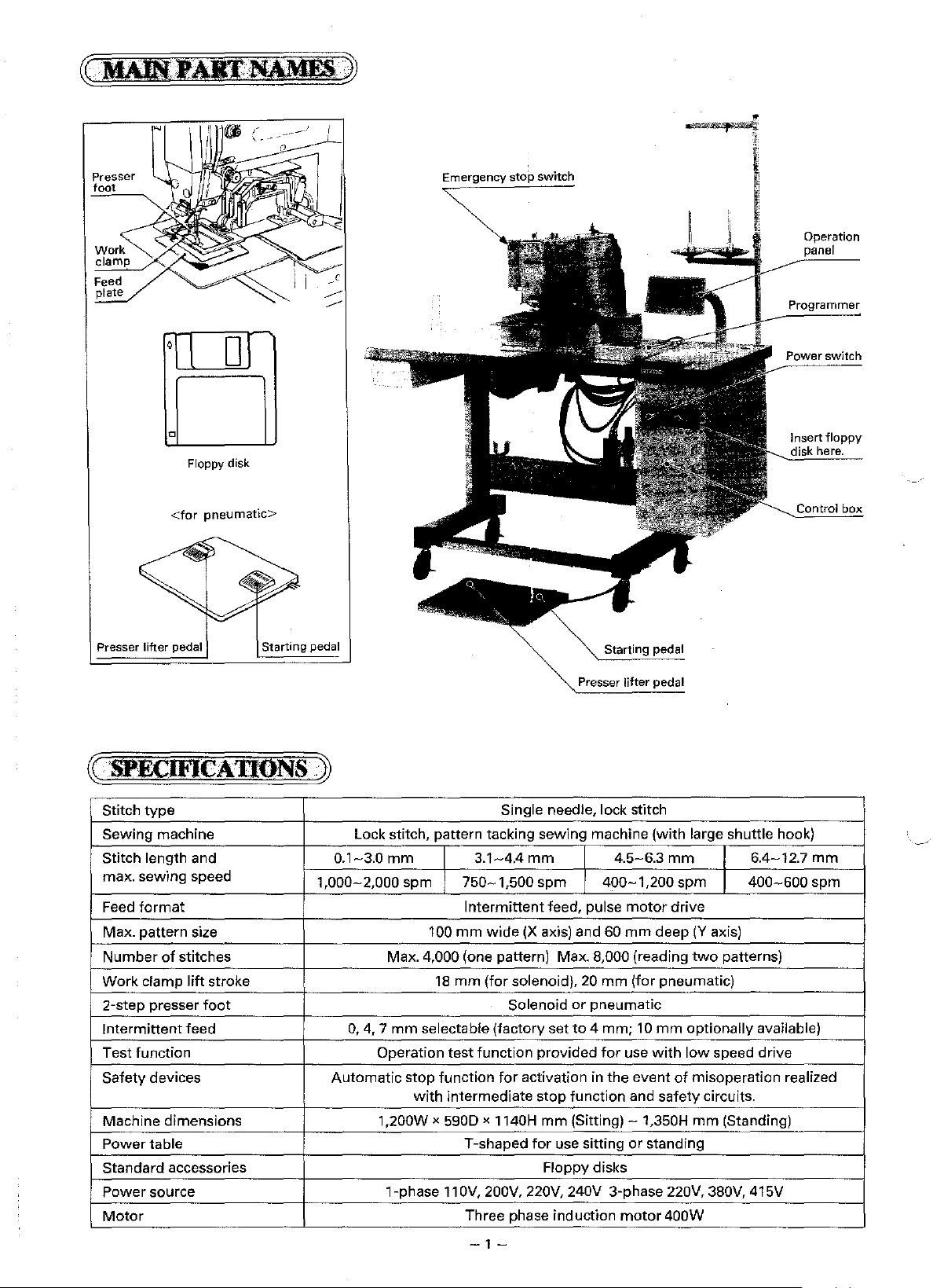
Emergency stop switch
Operation
~~
1
or
Floppy disk
<for pneumatic>
Presser lifter pedal
~-
'SPECIFICADONS
Stitch
type
Sewing
Stitch length and
max. sewing speed
Feed
Max. pattern size 100
Number
Work
2-step
Intermittent
Test function Operation
Safety devices
Machine dimensions
Power
Standard
Power
Motor
machine Lock stitch, pattern tacking sewing machine
format
of
stitches
clamp
lift
stroke
presser
table T-shaped
source
foot
feed
accessories
Starting pedal
--~
1,000-2,000 spm
0.1-3.0
Automatic
mm
Max. 4,000 (one pattern) Max. 8,000 (reading
0,
4, 7 mm
1,200W x 590D x 1140H
1-phase
stop
Single needle, lock stitch
3.1-4.4
750-1,500
Intermittent
mm
18
mm
selectable (factory set
test
function
function
with
intermediate
11
OV,
Three phase induction
mm
spm
wide
(X
axis) and 60
(for
solenoid), 20
Solenoid
provided
for
activation in
stop
mm
for
Floppy disks
200V, 220V,
Starting pedal
Presser
lifter
(with
large shuttle hook)
4.5-6.3
400-1,200
feed, pulse
mm
or
pneumatic
to
4 mm; 10
for
the
function and safety circuits.
(Sitting)-
use sitting
240V
3-phase 220V, 380V, 415V
motor
mm
spm
motor
drive
mm
deep
(Y
two
(for pneumatic)
mm
optionally
use
with
low
event
of
misoperation realized
1,350H
or
mm
standing
400W
6.4-12.7
400-600
axis)
patterns)
available)
speed drive
(Standing)
Power switch
Control
mm
spm
-1-
Page 5
~
INSTALLATION
[j]
Positioning
·~
ill
Installation
of
spool stand
.lJ
=
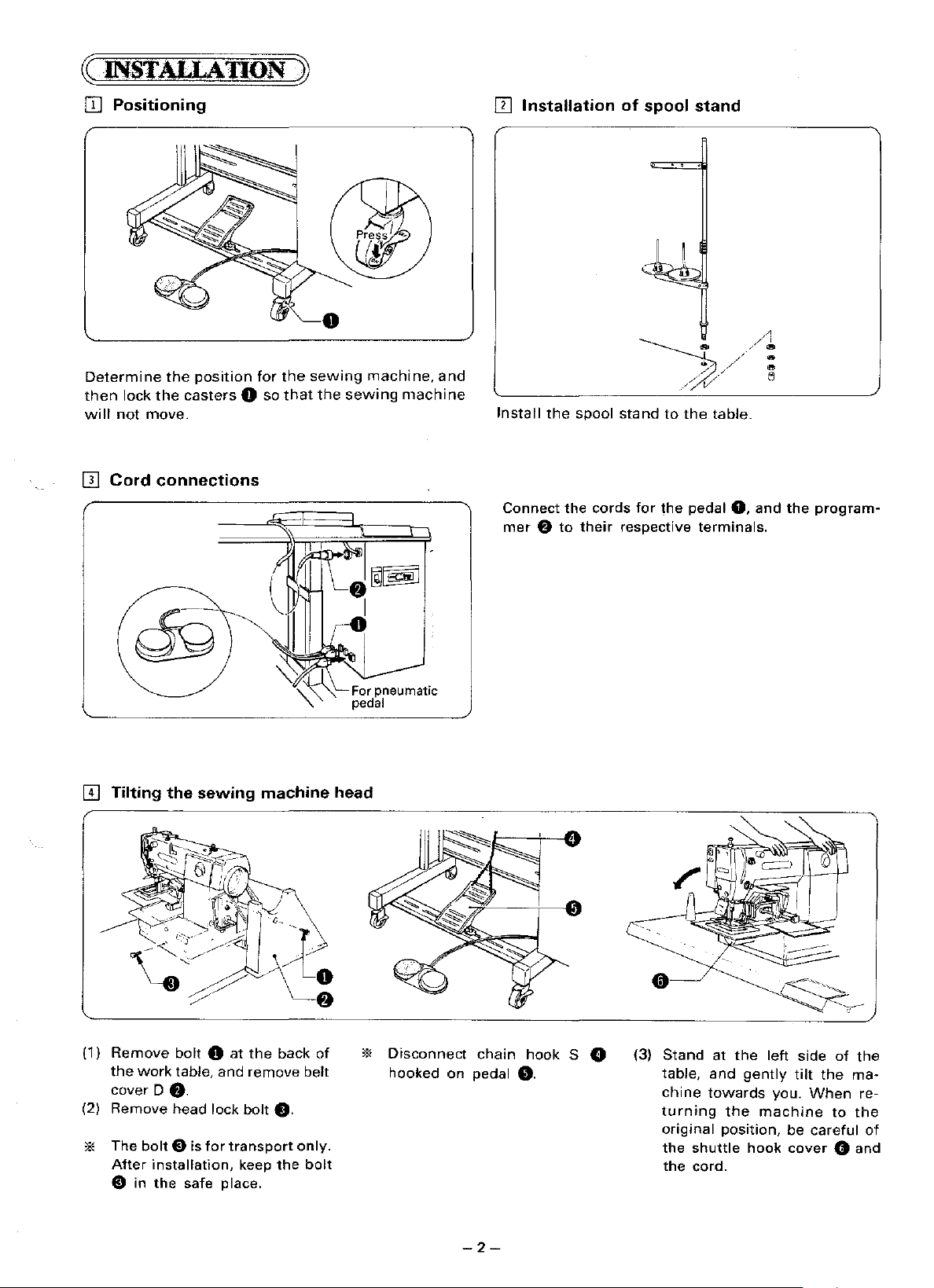
Determine
then
will
not
[II
Cord
[I]
Tilting the sewing machine head
the
lock
the
casters
move.
connections
position
0 so
for
the
that
sewing
the
sewing
machine,
machine
For pneumatic
pedal
and
Install
the
Connect the
mer e to
spool
cords
their
stand
to
for
the pedal
respective
the
table.
terminals.
0,
and
the
program-
(1)
Remove
the
cover
(2) Remove head lock bolt
* The
After
e in
bolt 0
work
table. and
D
8.
bolt
E) is
installation,
the
safe place.
at
for
transport
the
remove
f).
keep
back
the
of
belt
only.
bolt
*
Disconnect
hooked
on
chain
pedal
-2-
hook
0.
S 0
(3)
Stand
table,
chine
turning
original position, be careful of
the
the cord.
at
and
towards
the
shuttle
the
gently
machine
hook
left side
tilt
you.
When
cover
of
the
to
0 and
the
ma-
re-
the
Page 6
!}]
V-belt tension
1Il
Adding oil
Rotation direction
-~-
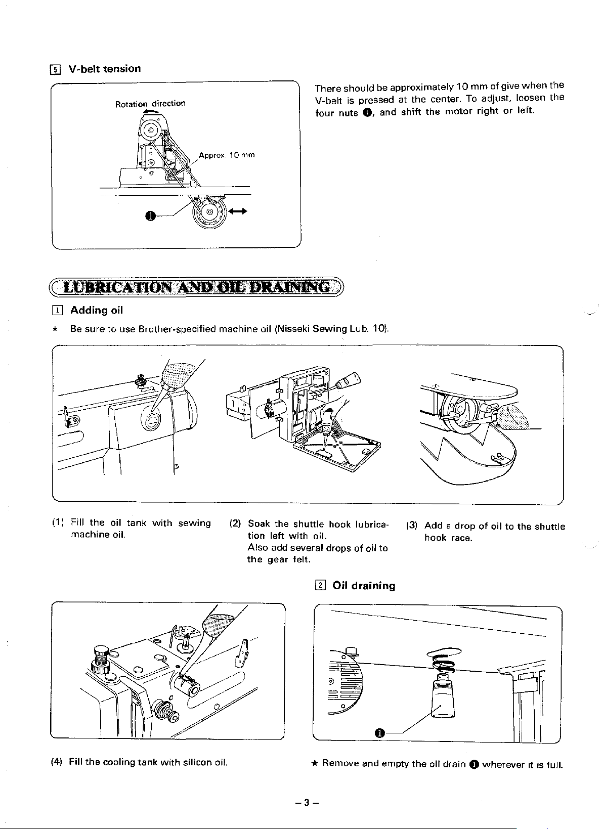
There
V-belt
four
should
nuts
be
is pressed at
0.
and
approximately
the
center. To adjust. loosen
shift
the
motor
10
mm
right
of
give
or
when
left.
the
the
* Be
(1) Fill
machine oil.
sure
the
to
oil
use
Brother-specified
tank
with
sewing
machine
(2) Soak the
oil (Nisseki
tion
Also
the
left
add
gear
Sewing
shuttle
with
several
felt.
hook
oil.
drops
ffi Oil draining
Lub. 10).
lubrica-
of
oil
to
(3)
Add a drop
hook
race.
of
oil
to
the
shuttle
(4) Fill
the
cooling
tank
with
silicon
oil.
-3-
*
Remove
and
empty
the
oil
drain 0 wherever
it is full.
Page 7
[j]
IIl
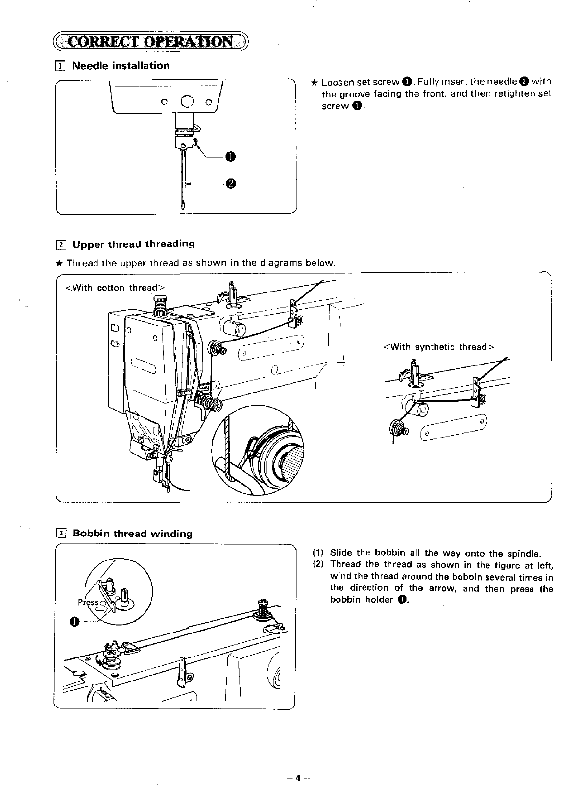
*
Thread
Needle
Upper
the
installation
thread
upper
threading
thread
c
~~
0
c~/
o,
!l.
•
@)
as
shown
in
the
diagrams
*
Loosen
the
screw
below.
set
groove
0.
screw
facing
0.
the
Fully
front,
insert
and
the
needle 0 with
then
retighten
set
ITl
Bobbin
thread
winding
(1)
Slide
(2) Thread
wind
the
the
direction
bobbin
the
the
holder
<With
bobbin
thread
thread
all the
around
of
the
0.
synthetic
way
as
shown
the
arrow,
thread>
onto
in
bobbin
and
the
the
several
then
spindle.
figure
press
at left,
times
in
the
-4-
Page 8
.:::<.1:::-f-!
"""'SPEED
.2@)-·
:: , ()
•0:>
,,,_
m•
IOlo
=
t
.AT,;;71b?
STEP BACK
I~
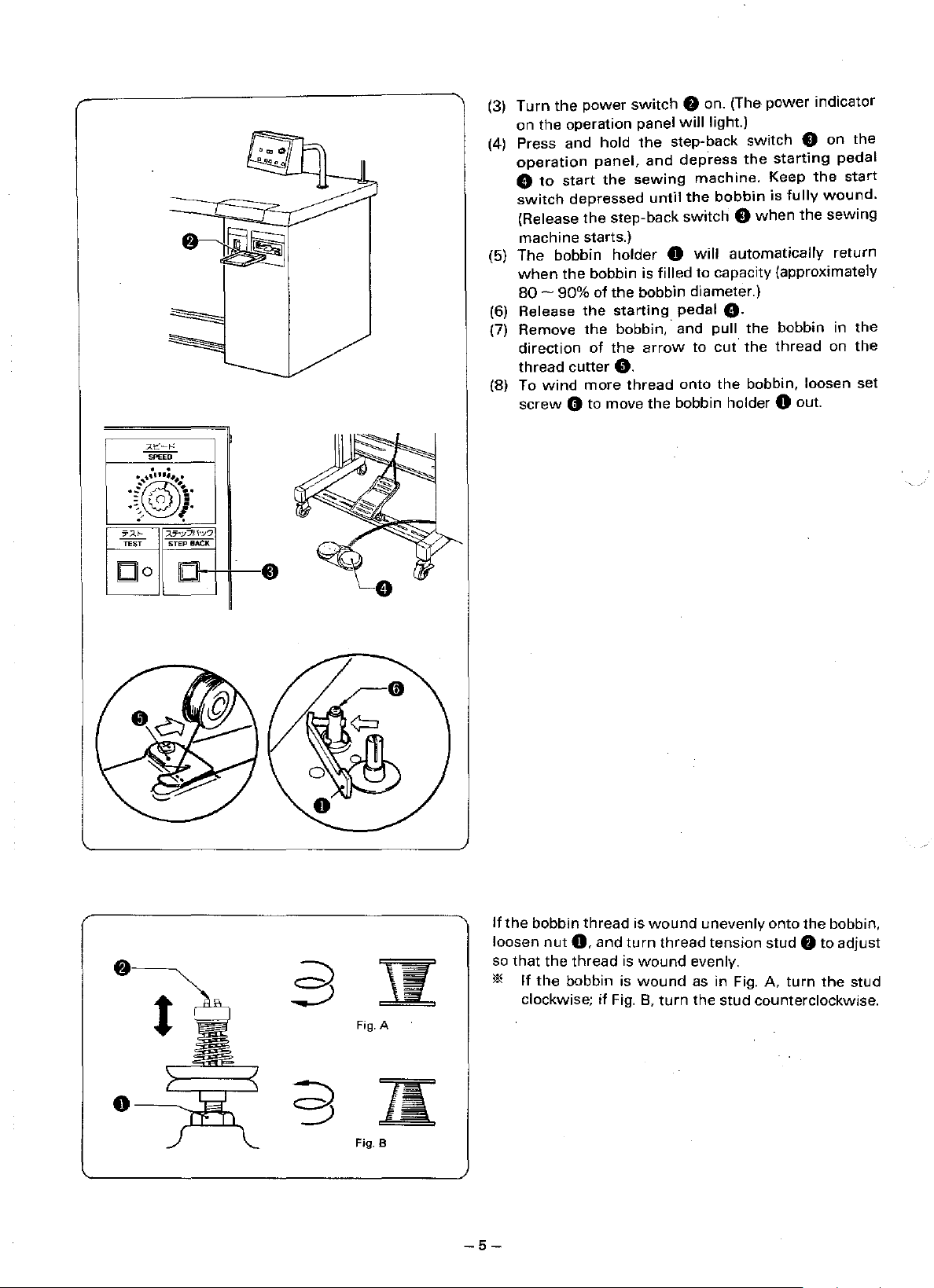
(3)
Turn
the
on
the
operation
(4) Press
operation
8
switch
(5)
The
when
(6)
(7) Remove
(8) To
and
to
start
(Release
machine
bobbin
the
80-
90%
Release
direction
thread
wind
screw e to
power
depressed
the
starts.)
the
cutter
switch
hold
panel,
the
step-back
holder
bobbin is
of
the
starting
the
bobbin,·
of
the
0.
more
thread
move
f)
on. (The
panel
will
light.)
the
step-back
and
dep.ress
sewing
bobbin diameter.)
arrow
the
machine.
until
the
switch 0 when
0
will
filled
pedal
and
to
onto
bobbin holder 0 out.
the
bobbin
automatically
to
capacity (approximately
8·
pull
cut·
the
power
switch
starting
Keep
is
the
bobbin
the
thread
bobbin,
0
fully
the
loosen
indicator
on
the
pedal
the
start
wound.
sewing
return
in
the
on
the
set
~
t
s
!I
Fig. A
1(
Fig. B
-5-
If
the
loosen
so
that
*
If
clockwise;
bobbin
nut
the
the
bobbin is
thread
0,
and
thread
if
is
turn
is
wound
wound
Fig. 8,
wound
thread
turn
unevenly
tension
evenly.
as in Fig.
the
stud
onto
the
bobbin,
stud
f)
to
adjust
A.
turn
the
stud
counterclockwise.
Page 9
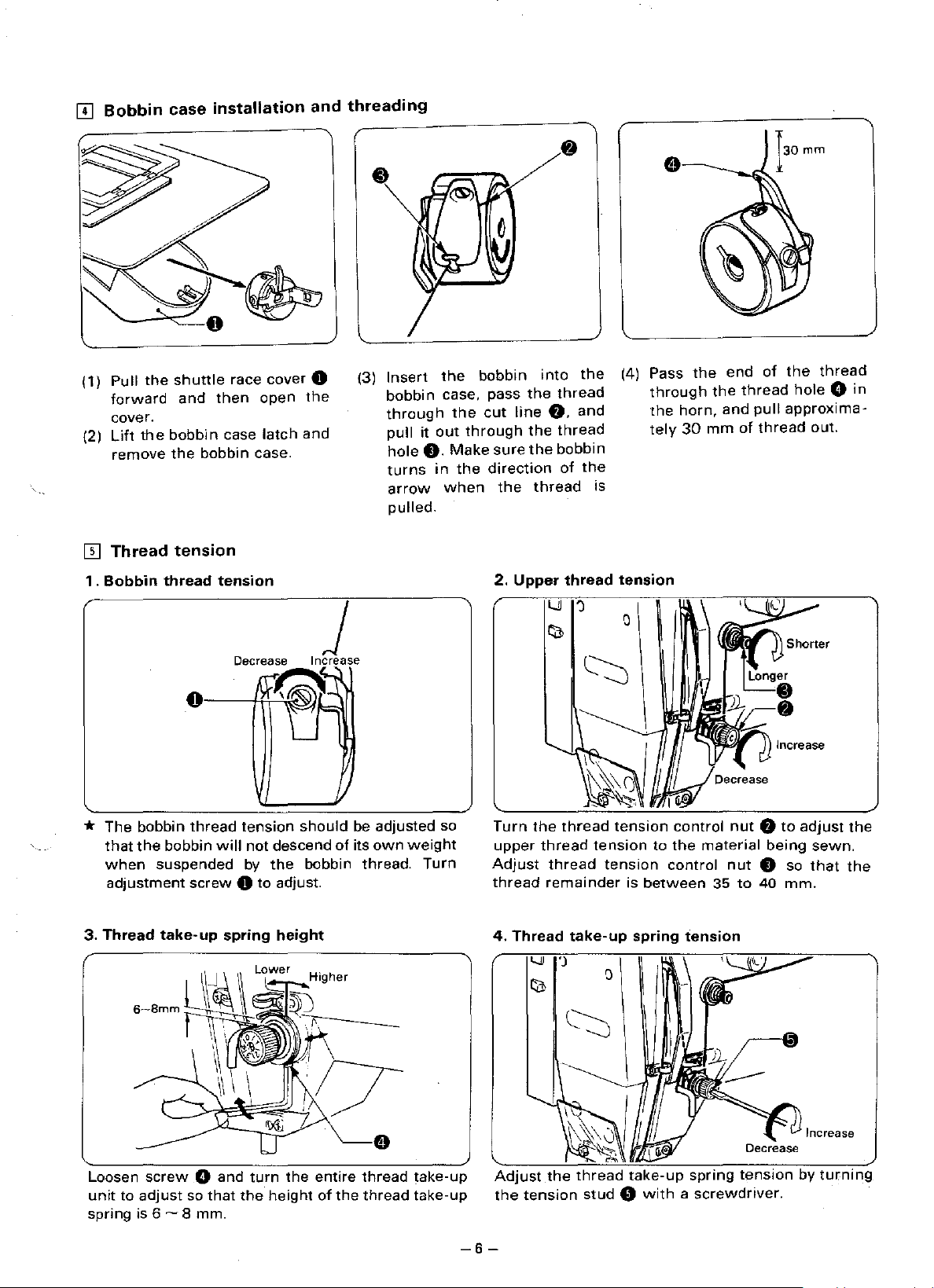
(1) Pull
(2)
III
1.
the
shuttle
forward
cover.
Lift
remove
Thread
Bobbin thread tension
the
and
bobbin
the
bobbin
tension
then
race cover 0
open
case
latch
and
case.
the
(3)
Insert
bobbin
through
pull
it
hole
0.
turns
arrow
pulled.
the
bobbin
case, pass
the
cut
out
through
Make
sure
in
the
direction
when
the
2.
into
the
line
0,
the
the
thread
Upper
the
thread
and
thread
bobbin
of
the
is
thread
(4) Pass
through
the
tely
tension
the
horn,
30
mm
end
the
and
of
thread
pull
of
thread
the
thread
hole G in
approxima-
out.
* The bobbin
that
the
bobbin
when
adjustment
3.
Thread
suspended
take-up
0
thread
will
screw
~
J
9
Decrease Increase
A
{~~'j
'--
tension
not descend
by
should
the
bobbin thread.
0 to adjust.
spring
height
Lower
/.,
be adjusted so
of
its
own
weight
Turn
Turn
upper
Adjust
thread
4.
Thread
the
thread
thread
thread
remainder
take-up
tension
tension
tension
to
is
between
spring tension
control
the
material
control
nut 0 to
nut
35
to
being
0 so
40
mm.
adjust
sewn.
that
the
the
Loosen
unit
spring is 6 ~ 8 mm.
to
screw
adjust
G and
so
that
turn
the
the
height
entire
of
the
thread
thread
take-up
take-up
-6-
Adjust
the
tension
the
thread
take-up
stud 0 with a screwdriver.
spring
Page 10
~
..
OIIBA!MG·PROQ.HJJ)(Jt'·~
[j]
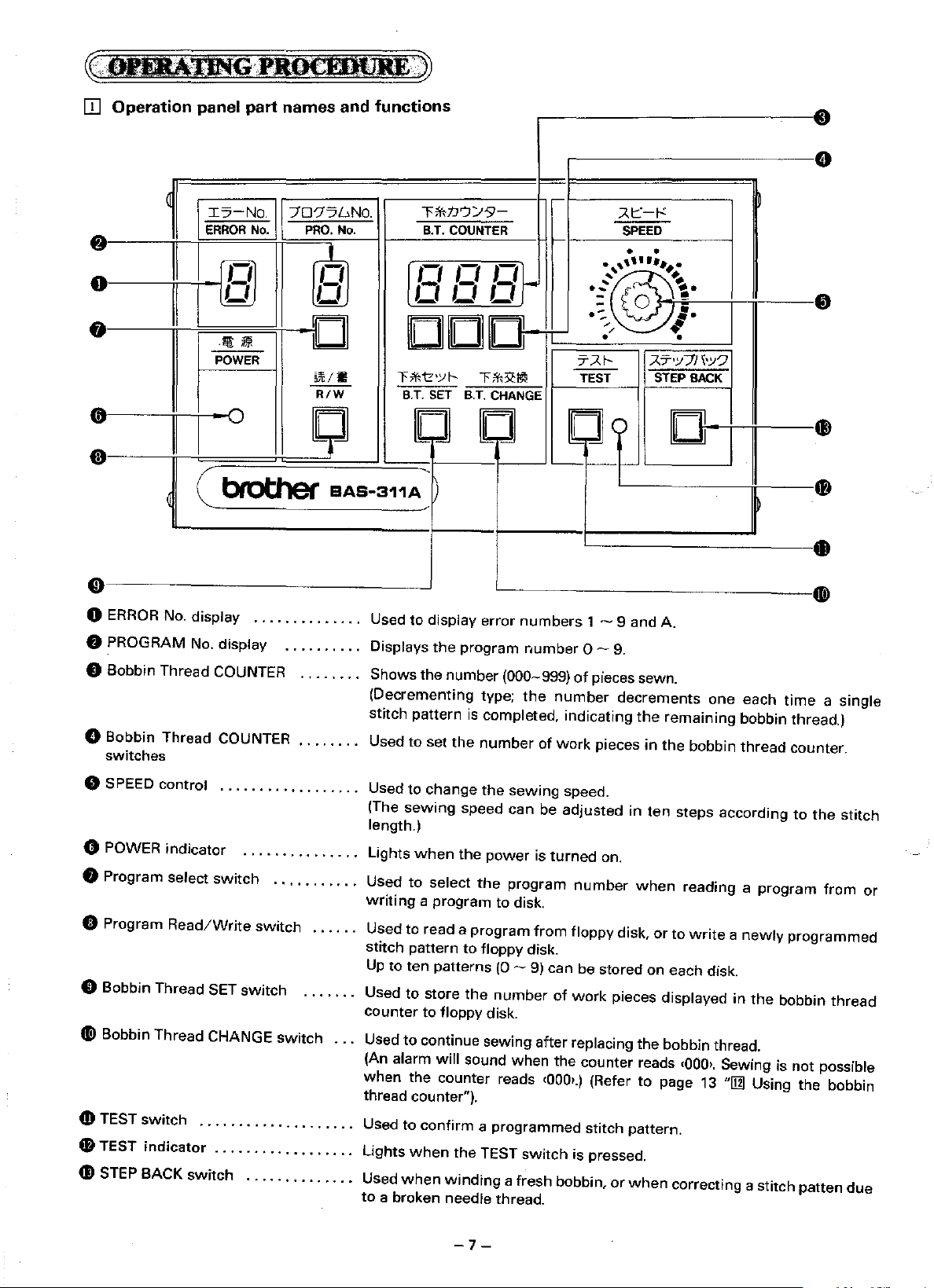
Operation panel part names and functions
....
""'
•
Ic:>-No.
ERROR
No.
70'7?wNO.
PRO.
No.
,_,
0
li
II
[@
Ll
I
.
!Jt
POWER
•0
I
l>i
II
(@
n
-
D
511:/W
R/W
[]
LILIU
CllCllD-
T;\'<'\z•yf-
B.T. SET B.T. CHANGE
[]
'
(
bf'ot:her
0
ERROR
0 PROGRAM No. display . . . . . . . . . . Displays
No. display
..............
BAS·311A
Used
to
T;\'<tJ')Y9-
COUNTER
B.T.
,_,
,_,
T;\'<:R:Ill
[J
~
display error
the
program
'
f-
1-
i-
' .
.....
: ;
~-
·:.
TAf-
--
TEST STEP BACK
[]o
'----
numbers
number 0-9.
1 - 9 and A.
).t:::
SPEED
• •
1-'
~
~·
,.
•
AT'Y71b?
D
•
O Bobbin Thread COUNTER . . . . . . . . Shows
(Decrementing type;
stitch pattern
C) Bobbin Thread COUNTER
switches
0 SPEED control
0 POWER indicator
8 Program select
0 Program
0 Bobbin Thread SET
II
Bobbin Thread CHANGE
4D
TEST
ID
TEST
Read/Write
switch
indicator
..................
...............
switch
switch
switch
. . . . . . . . . . . . . . . . . . . . Used to
. . . . . . . . . . • . . . . . . . Lights
...........
. . . . . . Used to read a
. . . . . . . Used
switch
Used to set
Used to change
(The
length.)
Lights
Used
writing
stitch pattern
Up
to
counter
. . . Used
(An
alarm will sound when the counter reads
when
thread
the
number (000-999)
the
is
completed, indicating
the
number
the
sewing
sewing
when
to
ten
to
to
the counter reads
counter").
when
speed can be
the
power
select
a program to disk.
store
to floppy disk.
continue sewing after replacing the bobbin thread.
confirm a programmed
the
program
to
floppy disk.
patterns
the
the
TEST
program
(0-
number
switch
of
pieces sewn.
number
of
work
speed.
adjusted
is
turned
from
floppy disk,
9) can be stored on each disk.
of
•000>.)
decrements
the
pieces
number
work
(Refer
stitch pattern.
is pressed.
in
in
ten
on.
when
pieces displayed
to
one
remaining
the
bobbin
steps according
reading a
or
to
write a newly
•000>.
page
13
each
time
a single
bobbin thread.)
thread
in
Sewing is not possible
"[j]
counter.
to
the
stitch
program
the
Using the bobbin
from
programmed
bobbin
thread
or
G)
STEP BACK
switch
..............
Used
when
winding
to
a broken needle thread.
-7-
a fresh bobbin,
or
when
correcting a stitch patten
due
Page 11

[I]
Using
the
* Programs
disk.
floppy disk
for
up
to
ten programs each containing up to a
maximum
4,000 stitches
can
be stored on each
floppy
(1)
Turn
the
power
(2) Hold
(3) To eject
* Slide
'*
*
the
disk 0
click
into
the
the
accidental erasure of the disk contents.
Inserting the disk into the drive upside
writing
Be
telephones,
exposure
of
sure to store your disks
place.
disk, press
write
data.
and
of
the
switch
with
protector 0 on
disk
other
to
0 on.
the
label up and
the
eject
devices.
oil
or
dust.
~~
the
metal
shutter
button
away
Magnetism
G.
the
back
of
the
down
or
backwards
from any magnets or magnetic sources, including radios, televisions,
can erase or damage disk contents. Also, be careful to prevent
disk
to
up
the
(the
may
'
!"
!
front,
window
damage
Unlocked, writing possible
Locked,
writing
and
insert
the
disk
into
the
opens)
the drive and will prevent reading
to
lock
the
disk and prevent
impossible
drive
O.
It
will
or
[]]
Using production counter
.-----,,-----~,.----
7D-7:JL!No
PRO.
No.
·x~~
·..
• ·-
~
·,
~in9
p!OOucliOQ
am
not be done while displaying the PRODUCTION counter.
""F*1J'")::JS'-
B.T.
COUNTER SPI
counter
Will
be displayed only after step
.At=:
...
.,
®
Both
PRO.
NO.
and B.T. COUNTER displays are available
for
the
four-digit
(1)
While pressing the TEST switch
SET
switch @. The test lamp 8 will light to display
the production count on both
COUNTER displays .
(j) Press the
TION
® Using the
be set from 0000
(2)
Press the TEST switch
out and all displays will return
play.
PRODUCTION counter .
BT
CHANGE switch @.The PRODUC-
counter will display 0000.
keys®,
the PRODUCTION counter
to
9999.
0.
(1).
0,
press the
PRO.
NO.
and
The test lamp 8 will
to
their
former
B.T.
B.T.
can
go
dis-
-8-
Page 12

[!]
Using
* By successively reading the
ches.
(1)
Set the DIP
(Refer
(2)
While pressing the EMERGENCY STOP switch,
The stitch pattern stored in the machine
(3)
In
(4)
When
stitch pattern.
put
8,000
stitch
SW@
to
page 26, "DIP SWITCH SETTINGS".) .
two
stitch patterns successively.
stepping
sewing
No.2
on
the starting switch, the second stitch pattern
to
ON. This
mode
two
stitch patterns
will
in
8,000 stitch sewing mode,
enter 8,000 stitch sewing mode.
turn
on
the
will
be erased.
power,
then release the EMERGENCY STOP sw1tch.
input
it
is possible
will
be sewn directly after the first
to
sew
up
to
8,000
stit-
input
NOtE:
[]]
Using
* By
using
.NOTE:
.
(1
I Set the DIP
(Refer
to
(2) Turn on
"1"
will
will
be
(Ex)
When
order.
(3)
*
When
When
pressing
(The
Pressing
stepping
reading
PRO.
The
rl\ao~
the
*tcond
single
single
As to spHt sewing, refer
grammer"
SW
page 26, "DIP SWITCH SETTINGS".)
the
be
displayed
displayed
the
the
NO.
the
will
jump
stitch
from
stitch J!llltt&m; · :
split
mode
split
mode,
(a
separate volume). .
@ No.1
power,
new
step back switch.
R/W
input
on
in
order.
three
patterns are
on
the
stitch patterns into
display
switch
it
IQ
to
ON.
the
the
PRO.
starting
switches
and
the
is
possible
th@
illstru~on
This
pattern
NO.
display.
programmed
switch,
from
displayed
the
final stitcll
to
change
will
enter
programmed
When
only
the
the
machine
1,
2 ...
stitch pattern
1]1anual
single
pressing the
with
split
pattern
from
to
9, 0.)
ofthe
fn-s~
up
to 9 patterns
of
.the
"e~.tromc
split
mode.
with
split
sewing,
displayed
the
floppy disk, press
will
Stitch pattern 'i,nj)Uno
immediately.
"1
'
'\ ' -:
,,-,
'-'
q '
··
· . • . ., _ . •
switch,
switches 1, 2, 3, 1, 2 ... in
PRO.
NO.
the
program select switch
read
into
sewing.
program
the
display
on
be
newly
P~'1'ammabl&
select
the
the
~rtlng
,•;,
. ·
'-
--' --
PatterQ
the
display
the
~et
program
can be sewn.
machine.
point
of
- - -
prq-
numbers
while
.•
that
-9-
Page 13

[ID
Using
the
program
R/W
{Read/Write)
switch
I5-No.
ERROR
•
POWER
0
No.
l.!R
7D-75L>No.
PRO.
No.
!Iii/&
R/W
* Programmed
can
be
patterns
storage and later recall.
(1)
Insert
the
contain
(2-
1)
To
Press the
play the number
PRO.
the
program number, press the
indicator
the
PRO.
When the
out
and the
the
number of the stitch pattern, reading is completed.
play @ will blink. Blinking will stop after the home
position is detected.
(2
- 2) To WRITE a pattern to
Press the
lect
the
ing the pattern
R/W
the
and a "P." will be displayed on the
while
the data is being read .
Pattern
sounds and the indicator 0 goes
NO.
display returns
completed.
stitch
patterns stored on floppy disk
read into
can be
the
memory,
written
floppy disk 8
programmed stitch pattern.
and
newly
to
disk
containing
programmed
for
permanent
or
which
READ a pattern to memory
PRO.
NO.
8 on the operation panel
of
the programmed stitch pattern in
NO.
display @.
0 will light, and a
NO.
display while the data
alarm sounds and the indicator 0 goes
"P"
on the
At
this time, the
After
R/W
"P"
PRO.
NO.
number
selecting the desired
switch
0.
will be displayed on
is
being read.
display changes to
on the
PRO.
disk
PRO.
NO.
8 on the operation panel to se-
desired program number.
with
the stitch programmer, press
switch
writing
0.
The drive indicator 0 will light,
onto disk will start
to
its
former
After
PRO.
when
out
and the
display,
programm-
NO.
is to
to
dis-
The drive
NO.
dis-
display
the
alarm
PRO.
writing
is
-
10-
*
If
an error
If
an error message code
the
Press the emergency stop switch 0 on the
the machine
then refer
ERROR
message
No.
to
to
and
is displayed
(1 -9,
display
stop sewing machine operation, and
follow
0.
and alarm will sound.
the
error code list on page
27.
A) is displayed in
front
of
Page 14

[I]
Using
the
STEP BACK switch
:TA-l-
TEST
A.7'Y7/I'Y?
STEP
BACK
* This
(1
I Press the emergency
(21
(3)
(41
(51
*
switch
at a time
resewing in the
bin thread runs
return
out. This is
chine is running.
emergency
Press the emergency
emergency
Press the
reverse one stitch at a
switch
When
position, release the step back switch.
clamp is stopped
back switch again
movement.
The machine
pedal (!) is pressed.
Turn
pedal(!)
forward. The
units
is used
in
the reverse sewing direction to enable
to
the
especially useful
stop
stop
STEP
is
depressed.
the
presser
the TEST switch 0 on and press the starting
to
move
if
the
STEP
to
move
the machine one stitch
event
the thread breaks
out
in mid-pattern. Use this switch
point
where
All
lamp
lamp
BACK
foot
too
to
will
start sewing
the presser
work
clamp
BACK switch is pressed at this time.
the thread broke
with
stop
switch 0
operations
will illuminate.
stop
switch 0 once again. The
will
go
out.
switch
0.
time
as
has returned
soon,
resume reverse
foot
will
or
the
bob-
or
run
large patterns.
while
the
ma-
will
stop and the
The
work
clamp
will
long
as
the step back
to
the
des~red
If
the
work
simply
press the step
work
clamp
when
the starting
one stitch at a
advance in 100 stitch
time
to
l
[[]
Adjusting
the
sewing SPEED control
A.t::-r-:
SPEED
(1
I The actual sewing speed can be adjusted in ten
steps
stitch
(21
Refer
speeds.
Stitch length
through
length. Turn
to
0.1-3.0
3.1-4.4
4.5-6.3
6.4-12.7
the sewing speed ranger
SPEED
the table
(mml
control 0
below
for
Sewing speed (spml
for
to
adjust.
allowable sewing
1,000-2,000
750-1,500
400-1,200
400-600
each
-11-
Page 15

w Using the TEST switch
77..1--
TEST
7..7'Y71b?
STEP
BACK
* Use the TEST
desired
thread runs out.
(1)
Press the emergency
ing machine is running. (All operations will stop, and
an
alarm
(2)
Press the
thread
(3)
Press the starting pedal ft.
The
work
ing
start position.
(4)
Press the TEST switch
light.
(5)
Press the starting pedal ft. (The needle
stationary as the
pattern at
presser
clamp
switch 0
time.)
(6)
When
press the TEST switch
and the
clamp
8 again
(7)
Sewing
pressed.
* The
work
by
pressing the STEP BACK switch 0
TEST
switch
0
to
fast forward.)
switch
point
when
will
sound.)
emergency
cutter
will
clamp
low
lifter
pedal 0
was
stopped
to
advance the
the
work
test
indicator 0
was
stopped
to
proceed.
will
start
clamp can be
8 is on. (Press the presser
to
begin sewing again
the thread breaks
stop
switch 0
stop
switch 0 again. (The
operate and the alarm will stop.)
will
move
automatically
$.
The test indicator 0 will
work
clamp advances
speed one stitch
to
fast
forward.
too
late, press the STEP BACK
work
clamp one stitch at a
clamp
reaches
8.
The
work
will
too
early, press the TEST switch
when
the starting pedal 8 is
forwarded
or
the bobbin
while
to
will
through
at
a time. Press the
If
the
desired position,
clamp
go out.
If
in 100 stitch units
lifter
from
any
the sew-
the
sew-
remain
the
work
will
stop,
the
work
when
pedal
the
the
[j]J
Using the emergency stop switch
(3)
If
a
problem
If
an
abnormal
activated, all
emergency
occurs
load
operations
stop
mode.
is
applied
stop,
or a problem
and
the
alarm
occurs
during
sounds. Press
-12-
* Press
(1)
*
(2)
The
sewing,
the
emergency
stop the sewing machine during actual sewing or
when
in
the
test mode.
If
the
emergency
sewing.
All
operations
Correct
switch
emergency
alarm
There
is pressed
on
If
the
All
when
the
0 again. The
will
will
(the
alarm
the
emergency
test
mode.
operations
emergency
the
the
the
will
problem,
stop
stop.
be no response
when
is sounding).
will
emergency
emergency
emergency
stop
stop
switch
stop,
and
and
press
thread
function
the
stop
stop function
will
emergency
switch
stop.
and
stop
switch 0 is
stop
stop
switch 0 to
when
function
switch
to
0 is pressed
an
alarm
the
emergency
cutter
will
be cancelled,
either
stop
0 is pressed
an
alarm
will
be
is
automatically
immediately
will
operate.
foot
switch
will
pressed.
cancel
while
sound.
stop
the
and
the
switch
0 is
during
sound.
cancelled
the
Page 16

[j]
Shifting a stitch pattern
r
I
7D?7L..No
PRO.
No.
-
fJJ
D
t.l'&;a
R/W
[J
1
~
T*-1J'J"J9
B.T. COUNTER
·n
l
DEllG
"'F*"t''Yf-
B.T. SET B.T. CHANGE
---tj
.--------,
®
' '
...
: 1
I I
L---;;-
l
;zt::
SPf
•
.
-I
LU
Ttf.::~~
L_
,,,.
~
...
',.......-,
.
-::,
·~;~
',
•
r::Zt-
TEST
-~...-
....
I-
8
[l-1:'
~
... ©
•
...
®
__ J
.@
* The relative position
stitch pattern
(1)
Press and hold
R/W
switch
<
,:;
..:;
<))
Press bobbin thread counter switch ®
pattern 1
@ Press bobbin thread counter switch ®
pattern 1
® Press bobbin thread
tern 1
pulse
@)
Press bobbin thread CHANGE switch @
pattern 1
*
At
this time, the
synchronizer and the home position sensor which
are operating.
Y~home
X-home
(2)
position
position
After
fine adjustment
pleted above, press the TEST switch
dicator
and the stitch pattern shift mode will be cancelled.
can
8.
> will appear in the bobbin thread counter
pulse
pulse
(0.1
pulse
sensor-------t
sensor
0 and bobbin thread counter 0 will go out,
of
a previously programmed
be shifted
the
TEST switch 0 and press
The test indicadtor 0
(0.1
mm) left .
(0.1
mm) right.
mm) up.
(0.1
mm) down.
PRO.
up/down
SET
switch ©
NO.
display 0 will indicate the
~Needle
._w..
I U Timing signal
(synchronizer)
"(f
----1.-r-e
....,....
...
Needle down
L__
(synchronizer) ·
of
the
pattern position is com-
and right/left.
will
to
to
to
shift the pat-
to
up
stop
(synchronizer)
stop
0.
The test in-
the
light, and
0.
shift the
shift the
shift the
signal
signal
[j]
Using the bobbin thread counter
T7f<1Y:>>9-
B.T.
COUNTER
,-,
,-,
0
C.t
C.t
DDD}t--•
T
i\\t?
'Y
t--
Ti\\:\Zill!
B.T.
SET
B.T.
CHANGE
-
•
DJ
-
D
,-,
•
-
""
* Set the bobbin thread counter
of
pieces
with
running
tern.
(1)
Press the bobbin thread counter switches 0 to display the
counter8.
the
out
number
of
the selected pattern which
amount
of
thread on the bobbin to avoid
of
bobbin thread in the middle
of
work
to
display the number
can
be sewn
of
a pat-
pieces in the bobbin thread
* The bobbin thread counter can be set to any number
from
<
001 > to
< 000
>,
sewing continues irrespective
amount
(2)
Insert the
SET
record the
bin thread counter
(3)
The
one each
the
sewn, the counter 8
will
the start switch is pressed.)
(4)
Press the bobbin thread change switch 0 and re-
place the bobbin. The alarm will stop, and the number
again in the bobbin thread counter
of
bobbin thread remaining.
floppy
switch
number
number
time
number
sound. (The sewing machine will not start even
of
work
< 999
>.
If the counter is set
of
the
disk and press
0.
An alarm will beep twice. This will
of
work
8
to
the disk.
shown in the counter 8 will decrease
the stitch pattern
of
patterns shown in the counter
will
read <
pieces set in step
the
bobbin thread
pieces shown in the bob-
is
completed. When
000
>,and
(2)
will be displayed
8.
an
alarm
to
is
if
-13-
Page 17

(1)
Turn
the
power
(2)
Insert the
(3)
Press the
(4)
Press
(The
the data is being read.
will
(5)
Step
(6)
Insert
the clamp.
floppy
PRO.
R/W
switch
floppy
go
on
disk drive indicator
out, then the
the presser
the
work
switch
0 on. The
disk
f,J.
No. selection switch 8
power
0.
will
When
reading
piece
program
lifter
under
no. display
switch 0 to
the
work
:10'.75/..>No.
PRO.
Iii/a
indicator on the operation panel
to
select the desired
light
and the
is
completed, an alarm
will
raise the presser foot.
clamp, and press the presser
No.
R/W
program
blink the
program
no. display
program
will
light.
number.
will
show
a P
will
sound and the indicator
number.)
lifter
pedal 0
to
while
lower
*
*
(7)
(8)
(9)
Shuttle
When
working
quired, press the manual
piece, and then press presser
Press the starting pedal
to
the
sewing
gram
is
sewing.)
Press the starting pedal 0 again
After
sewing is completed, the thread
clamp
will
of
sewing can be continued since
time.
hook
lubrication
with
small pieces
work
0.
(The
start position and blinking
rise.
When
the
power
which
are hard
clamp lifter pedal
lifter
pedal0.
work
clamp
will
to
start sewing.
cutter
is
turned
on
the
machine still stores the sewing data
to
position,
(i)
(This is convenient
will
return
stop. This is only required the
will
automatically operate, then the
after
once being
or
when
precise sewing is re-
for
precise positioning
when
sewing
to
the origin, and will then advance
turned
off, the same pattern
while
first
from
of
time
the
work
sitting.)
a pro-
work
the last
(1) Pull
forward
remove
the
to
the
shuttle
bobbin case.
hook
open.
and
cover
then
(2)
Slide
of
the
shuttle
tle
hook
the
tab 0 in
arrow, and
race
e.
body 0
-14-
the
direction
remove
and
the
shut-
(3)
Clean
pieces
shuttle
race.
After
add a
any
from
hook
cleaning
drop
of
dust
the
driver
thread
is
oil
to
and
thread
0.
the
guides
completed,
the
and
race.
Page 18

~
STANDARD
*Turn
[I]
Turn
needle
bottom
*
[I]
the
Needle
{DPx
the
pulley
bar
of
Align
Needle
machine
bar
a
5)
so
that
the
the
top
bar
pulley
height
to
completely
reference
needle
reference
lift
stroke
AWUSTMENTS
by
hand
adjustment
lower
line®,
bar
bushing
line
adjustment
®,
when
the
the
0.
with
making
needle
second
the
bar.
from
bottom
»
any
Remove
bott.om
adjustments
cap
reference
of
the
needle
f),
loosen
line
bar
set
screw
on
the
bushing
Q,
needle
when
and
vertically adjust
bar, is aligned
using
needle
the
with
the
DP x 5.
Turn
the
bottom
shuttle
*
Align
DP
1Il
Needle
the
X 5.
{DPx5)
pulley
hook
the
@
to
of
the
point
second
to
shuttle
raise
the
needle
is
aligned
from
hook
--ict-~-
needle
bar
bushing
with
top
reference
001-0.08
"--®
DPx
bar
from
the
point
0
17
the
0.
Now,
needle
line
gap
adjustment
mm
lowest
center.
@,
loosen
with
needle
Allen
the
bottom
position
screw
of
and
49
the
align
and
needle
turn
the
the
bar
bottom
shuttle
bushing
reference
driver
E) so
when
line®,
using
with
that
needle
the
Turn
the
pulley
connecting
and
link
stud e to
align
the
shuttle
adjust
hook
the
point
needle
with
to
shuttle
the
-15-
needle
hook
center. Loosen set
point
gap
to
0.01-0.08
screw 0 and
mm.
turn
the
eccentric
Page 19

IT]
Shuttle
Turn
the
pulley
connecting
will
result
point
will
[}]
Shuttle
driver
needle
0
and
align
the
link
stud
0 so
that
in skipped stitches.
interrupt
hook
the
needle, resulting
thread
contact
shuttle
the
shuttle
Also,
guide
adjustment
hook
point
with
driver
if
the
needle does
in
abnormal
adjustment
the needle center. Loosen set
meets
the
needle
not
sufficiently
abraison.
Adjust
thread
thread
8.
Note
so
that
guide
guide
contact
8 is
lightly
screw
that
excessive needle
the
shuttle
the needle
at
the
center
in, and then
Oand
driver,
groove
of
turn
the
eccentric
to
driver
contact
the
shuttle
of
the
shuttle
the needle, slide
retighten
the screws.
hook
hook
the
ffi
Two-step
Maximum
stopped.
(1)
Lower
plate 0 to
Now
(2)
Lift
presser
to
the
work
the
presser
tighten
work
0 mm,
work
clamp adjustment (independent presser
clamp 0 lift
plate
and
screw G and
plate 0 again,
clamp
0 is
f).
then
18
is
18
Loosen
tighten
nut
O.
and
loosen
mm.
mm
from
screw G and
screw
Q.
nut
the
needle
nut 0 to
Spring 8 will
0.
Adjust
-16-
plate
guide
top
adjust
be
minimally
stud
toot
solenoid type)
to
the
work
the
gap
0 so
that
clamp 0 when
between
tensioned at
the
the
height
work
this
from
the
machine
clamp 0 and
time.
the
needle plate
is
feed
top
Page 20

0 Movable knife adjustment
Loosen
the index on the needle plate
<{Replacing the movable and fixed knives}>
(1) Remove
nut@
screws
disconnect
and
the
move
connecting
f),
and remove feed
thread
cutter
rod L 8
when
the
machine is stopped.
plate
connecting rod 0
right
or
f).
left
so
Remove
from
stud
that
the
V-notch
screws 0 and
f).
@of
G.
the
movable
and
remove needle plate
knife 0 is even
e.
with
Now
Movable knife -------c;;t
washer
(2) Remove
new
the
necessary, use
to
the
movable knife.
movable
adjust
the
;-:::---~
~
movable knife,
Now
knife 0 and
the
provided movable knife
knives so
check
that
and
the
they
replace it
the
cutting
fixed knife
cut
properly.
with
edge of
0.
washer
~-
a
If
-17-
(3) Install
hole plate
the
fixed
G).
knife 0 0.5
mm
away
from
needle
Page 21

I1J
Presser
foot
adjustment
(4) Fit
*
the
thread
ing
lever
When
the
*
(1)
*
(2)
fitting
ing
lever
and
e.
bit
to
confirm
connecting
Turn
the
the
down
below.
Loosen
8
lightly
screwO.
If
the
presser
will
shift
too
high, skipped
Turn
the
enters the center of the needle hole
foot
f).
of
the
needle
and
turn
cutter
connecting
pin
o.
and
install
the
connecting
pin
0 and before
move
the
needle
that
rod
pulley
by
position,
screw
0.
against
foot
when
sewing.
stitches
pulley
by hand,
If
the
needle
hole,
the
presser foot (presser bar)
plate
the
movable knife 0 is
e.
hand
to
and
then
set
the
bottom
the
work
is
lowered
Also,
and
is
not
remove
may
rod 0 on
needle
lower
capo.
plate
rod 0 on
tightening
back
and
the
proceed.with
of
the
piece,
and
too
far,
if
the
occur.
make
sure
aligned
with
loosen
connect-
e.
the
connect-
screws
forth a little
pulled
presser
the
presser
then
tighten
the
work
presser
the
in
the presser
the
screw
to
adjust.
0
by
foot
to
steps
foot
piece
foot
is
needle
center
e.
[[]
Changing the presser
*
Maximum
mm.
4 mm presser 0
foot lift
standard
0
(1) To
(2) If vertical
change
intermittent
(There are
movement
the
presser
two
presser
lift
of
the
foot
indexes, 4
of
foot
presser
cam
and
the
presser
lift
foot
C)
7, on
lift
foot.
over.
the
foot
is 4
mm.
~I
remove
cam. The
is
Presser
0
7
mm
foot lift
nut
(small)
number
not
required, remove
-18-
foot
lift
on
presser
0.
nut
of
the
this
(large)
index
the
machine
8.
indicates
cam
e.
can be set
and
washer
the
0.
lift in
to
either 4 mm
and
then
millimeters.)
0
turn
or
the
7
Page 22

[jQ]
Wiper
adjustment
iapprox.
15mm
(1)
When the thread
the needle center. Loosen screws 8 and shift the entire solenoid bracket 0 up
* The standard
(2)
When
the
[ill
needle
Loosen
not strike
Needle
19
Needle
mm
tip
screw
the
and
up
wiper
solenoid plunger 0 is driven
height
wiper
should be approximately 2
presser foot 0
feed
position
from
the
solenoid bracket G bottom to
f)
is operated and aligned
0 and move
timing
Material
the
or
adjustment
wiper
needle.
~eed
Feed
e
mm.
f)
in
operating
stopped
with
or
out
;\:Y
to
the
center of
to
adjust. As
,
C\!J
the full stroke, the
the
needle plate
the
shown
~
2
mm
wiper
needle bar,
in Fig. A, make
Rotation
8 should be
or
down
top
is
approximately 131 mm.
the
distance
direction
to
sure
Fig.
adjust.
from
the
A
15
mm
the
wiper
wiper
0
in front
f)
f)
does
of
to
(1)
*
Adjust
Turn
Adjust
needle
material.
reflector 0 so
clockwise
the
has
to
needle
been
removed
that
lower,
and
the
needle
counterclockwise
feed
timing
from
the
with
material,
tip
is
19
mm
to
raise
synchronizer 8 so
and
so
-19-
1
above
that
the
the
the
stop
needle plate
position.
the
feed
-feed
mechanism
when
the
mechanism
stops
needle is in
begins
before
to
the
the
operate
needle
up
position.
after
enters
the
the
Page 23

IJ1I
"DIP
2-step
switch
work
clamp operation adjustment
®-1"
ON
=m
ON
=m
When
OFF;
The presser
When ON;
The presser
sewing
Dip switches
foot
foot
is
completed.
Turn the
operation panel.
(1)
will
rise automatically when sewing is completed.
will
rise when
power
Presser
settings
the
presser lifter pedal is pressed
off, then open the side cover
foot
of
motion
DIP
can be adjusted
switches®
1,
2,
3,
by
changing
4, 5 and
after
7.
of
the
the
«DIP switch
~~
®-2,
ON
ON
3,
4»
2:0N
3:0FF
First switch
Second switch
2:0FF
First switch
Second switch
2:0N
First
switch
Second switch
ON:-----'Work
3:0N
ON:-----'Work
3:0N
4:0N
ON:-----'Work
First
switch~
Second
switch
For
clamp left fJ, and the presser foot 8 will
neously.
will appear
pedal
*For
OFF.
4:0N
clamp right 0 descends.
ON: Work clamp
4:0N
clamp left 8 descends.
ON:
ON: Presser
Work clamp right 0 and presser
clamp right 0 and
o
pneumatic type, after sewing work clamp right
The
work
clamp (right and left} and the presser foot
as
below
when
they
is a two
solenide type, DIPSW
foot
position switch.)
left
8 and presser
0 descends.
work
descend. (The presser lifter
®-2,3
and 4
should
foot
0 descend.
foot
0 descend.
clamp left 8 descend.
all
rise
be
8,
work
simulta~
all
set
to
2:0N
3:0N
4:0FF
First
switch
Second switch
Start
switch
ON:-----Work
ON: No
ON: Presser
-20-
clamp
right
movement
foot
0 descends.
0 and left 8 descend.
Page 24

«DIP switch
®-5»
ON
The sening
ation
of
the
of
DIP
switch ® < 5 > determines the oper-
work
clamp during split
mode
operation.
Work clamp
cally during split mode oper-
ation.
«DIP switch
rises
®-7»
Normal
automati-
Work clamp
presser lifter pedal
during
Single pedal operation
rises
split mode operation.
when the
is
pressed
DIP
switch®
ation.
<7>
is used
to
select single pedal oper-
When the start switch is pressed, the
matically
drops, and sewing starts when the switch is re-
leased.
work
clamp auto-
-21-
Page 25

@]
Changing
uDIP switch
the
thread breakage detection stitch margin setting
®-5»
<Normal: 8 stitches>
1--1-...-.-j:::::
,__.__,o
<
14
stitches>
The thread breakage detection stitch margin setting
be set to either 8 or
of
DIP
switch®-< 5 >.
DIP
switch ®-< 5 > is normally set
(In
this position,
margin is 8 stitches.)
When this switch is set to
14
stitches.
NOTE:
NOTE:
If
the
thread breakage detector misoperates, set
the thread breakage detection stitch margin
stitches.
If
the
thread
breakage detector senses thread breakage,
ping the machine upon the third stitch regardless
of
the setting
14
stitches by changing the setting
to
OFF.
the
thread breakage detection stitch
ON, the stitch margin will be
is
broken during sewing, the thread
of
DIP
switch®-< 5 >.
can
to
14
stop-
[j]
Changing the feed speed
uDIP switch
®-8»
<Normal
ON
~1--1--i
speed>
....
....
0
The feed speed
of
DIP
switch®-< 8 >.
DIP
switch®-<
(Feed
speed: approx.
When this switch is set to
material at high speed.
(Feed
speed: approx.
can
be
changed by changing the setting
8 > is normally set
15
em/sec.)
ON, the machine can feed
25
em/sec.)
to
* If the material slips, set the switch
OFF.
to
OFF.
the
-22-
Page 26

[iiD
Changing
the
speed
at
the
start
and end of sewing
Be
sure
to
turn
off
the
power
before opening the control
box.
(1) The sewing starting and en?ing speeds
changed according
< 1 > and
«DIP switch
<2>.
©-1n
When
to
the settmg
OFF:
It
the first stitch.
of
DIP
will
be approx. 600 spm
~ON
ON:
It
will
When
be approx. 260 spm
the first
two
stitches.
~ON
?an
sw1tch
be
©-
for
for
(2)
By changing the setting
at its highest position since the upper shaft
«DIP switch
4 3 2 1 When
©-3»
of
OFF:
The machine
DIP
switch©-<
will
«DIP switch
4 3 2 1 When
- the last
©-2»
OFF:
It will be approx. 400 spm
two
[]__WoN
When ON: It will be approx. 260 spm
the
last
two
3 > on the
is
stop
motor
circuit board,
rotated in the reverse direction after the thread is trimmed.
with
the needle
at
its normal position.
the
machine can
be
stopped
stitches.
stitches.
with
for
for
the needle
mON
1
4 3 2
~ON
NOTE:
All
When ON: The machine
of
DIP
switch
©is
factory preset
will
stop
to
OFF.
with
the needle
-23-
at
its highest position.
Page 27

Jj]J
Using the memory switch
The
memory
memory
switch settings can be used
switch settings)
e
0
to
customize the
I-;;
~
lBl
70'1-::>L...No
NO
PRO. No.
I I
~
D
R
~~~
R/W
D
r:J
work
clamp's operation. (Refer
to
the
following
table
0
AI::'
""F:*1J'J/-9
B.T. COUNTER
[,'
I I I
n n
q~
1_1
DDD
Tii'<i?'~'~'-
T:'i':3Hi.!!
TAC
TEST
r.:
SPEED
. .
·,(@)
.~@
= 0 :
.-_>
~·
~·
J..7'V7! \•;;'?
STEP
BACK
D
8
.·~-to
of
the
(1)
While pressing
No.O
will appear on the
memory
the
(j)
"on"
or "oFF" will appear on the
® When the
order
of
switch
®
All
® Insert a
disk.
NOTE:
(2)
Press the
The TEST lamp E)
NOTE:
~
MEMQRX
The following are special uses. All
NO.
9-F
number
of
the
floppy
When memorizing
when the program including
All
of
Also, when the
switch are set
0 When moving
1
2
3
4
5
6
7
8 Presser crank flips over after
the
TEST switch
PRO.
switch number.
PRO.
No. switch 0 is pressed,
0,
1,
2,
...
9,
A, b,
will appear on the
memory
TEST
the
switch
disk, and press
the
switch
memory
$.
will
go
switch is factory preset
power
to
OFF.
SWITCH
When moving the sewing start
When moving
When moving the sewing start
The home position is changed
direction and then the X direction, and then reversely.
NOTE: When using the
OFF
Upon emergency stoppage, the machine stops
At
the sewing end position, the feeder passes through
At
the sewing end position, the
The presser foot remains lowered.
NOTE: The cycle
OFF
0.
No.
displayO,
B.T.
...
F,
0,
1,
will
be set
the
current
your
out, and the indication on each display will I be returned
is
turned on while pressing the EMERGENCY
SKt'llNGS
of
to
to
e o o
press the
COUNTER display 0 alternately when the
and simultaneously the
B.T.
to
B.T.
SET
memory
STEP
BACK switch@. The TEST
and
"on"
or
"oFF" will appear on the
the
memory
COUNTER display.
"oFF'
when the
switch E). The current
switch setting on the
setting is read
switch number on
from
to
OFF.
memory
B.T.
CHANGE switch 0 is pressed.
the
floppy
4~
lampE)
B.T.
the
PRO.
switch function corresponding
memory
floppy
switch setting
disk, this setting will appear automatically
disk drive.
STOP
switch, all the settings
will light, the
COUNTER display@ according to
STEP
BACK switch 8 is pressed.
No. display 0 will change in the
will
be stored on the
to
its original state.
~
the
memory
the home position, the feeder moves in the X direction, then
the home position, the feeder moves in
time
will
switch
position,
position,
to
work
clamp
work
be shortened
1/4
is
usually set
When
it
moves in
it
moves in the X direction, then
the forward position and
for
attaching buttons, set this switch
clamp rises, and moves to the sewing start position.
when
of
a pattern is sewn, and flips back after
-24-
to
OFF.
ON
theY
direction, then the X direction.
theY
direction, then
theY
the
feeder moves first in
to
with
the needle at its highest position.
the
first home position.
the
program includes many feed points.
3/4
ON.
memory
to
its
of
theY
direction.
the
X direction.
direction.
theY
is sewn.
switch
memory
floppy
the
memory
Page 28

Press
Press
Depress
Power
Insert
the
presser
switch
floppy
PRO No.
the
R/W
lifter
Test
switch.
switch.-
pedal. -
switch
START
on
disk
on-
-
-
-
- Reads
+--
program
Set the work piece.
+--Work clamp descends.
+--Test
lamp
illuminates.
from
disk.
Press the
Select
number.
Press
Press
the
(if
the
work
Power
switch
PRO
No.
the
program
the
R/W
presser
lifter
clamp is down).
To
change
on
switch -
switch.-
pedal
pattern
-
+-Read
-Work
__..
'*Replace
* Set material
program
clamp
plate;
confirm
descent.
from
rises.
presser
in
place.
disk.
foot,
needle
feed
Depress starting pedal -
Depress
starting
pedal -
Test
switch
off-
Depress starting pedal - -
-Presser
start
-Feed
(confirm
presser
operation.)
-Feed
+--Test
Machine,
} Max.
foot stops at
position.
drive
(pulse
needle
foot
and
stop
lamp
goes
feed
2.000
motor)
descent.
work
out.
operate.
spm.
sewing
clamp
Depress presser
Press
emergency
swtich.
Press
emergency
switch.
lifter
pedal.
When
bobbin
stop
stop
__..
thread
thread
__..
__..
breaks
runs
-Machine
sounds.
-*Remove
-Thread
alarm
or
out
cutter
stops.
)
stops,
problem
operates,
alarm
I
One
pleted
machine
+--Stop--thread
cycle
com-
Work
I
cutting
I
clamp
rises
-25-
Press
Press
step
step
back
back
switch.
__..
switch.__..
Work
-
stitch at a
direction.
-Work
clamp moves one
time
in reverse
clamp stops.
Page 29

« DIP SWITCH SEI'llNGS
~
0
Ot::J
®
@
NO.
1
2
3
4
5
6
7
8
®
When ON
Work clamp does not
Right
- left
two-step
Left - right
When the switches
and presser
Work
Presser crank
(Inner clamping device is optional.)
Single pedal operation possible using the starting pedal
Activates thread breakage
two-step
foot
clamp does
of
rise
when sewing completed
work
clamp (refer
work
clamp (refer
2,
3 and 4 are on,
will
descend
not
rise
inner clamping device
with
during
detector
left
two
split mode operation.
(Thread breakage detector is optional)
to
P.20)
to
P.20)
and right
positions. (refer
turns
to
the
work
other
©
[MMJI
clamps will descend at one time,
to
P.20)
side
NO.
1 Single
2
3 Thread
4
5 Thread breakage detection stitch margin setting can be set
6
7
8
split
mode
possible
8000-stitch sewing
trimming
Needle cooler can be used. (Needle cooler device
OFF
OFF
High feed speed
mode
possible
does not function
When
when
ON
emergency
©
NO.
1
2
3
4
The first
The last
The
with
OFF
two
stitches are sewn at
two
stitches are
upper
shaft
turns
the needle at its highest position.
sewn
in the reverse direction after thread breakage, and the machine stops
at
When
ON
low
speed (approx. 260 spm).
low
speed (approx. 260 spm).
-26-
stop
is
optional.)
switch is pressed.
to
either 8
or
14 stitches.
Page 30

·
..
•
NO.
1
2
3
4
5
6
7
8
9
A
Emergency stop switch pressed
Trouble
Over-area
Floppy disk not inserted,
Floppy disk is locked (write protected).
No program registered
Error occurred in program mode.
Thread breakage detected
Protection network activated because
No
with
the
motor
or synchronizer/Motor stopped
or
cable not properly connected
usable pattern data on disk
Cause
of
abnormal voltage
when
voltage dropped
-27-
Page 31

Page 32

BROTHER
INDUSTRIES, L TO.
NAGOYA.
JAPAN
151·311A
883Z11·002
1993,04,L~
Printed in Japan
 Loading...