

Brother BAS-302 User Manual
·.
...
*'"/[]~}'~
·
k~.:r~
~
·
~
>/;rJ7~1
. .
JVM
. . .
.
~
, I
PROGRAMMABLE
••
~FfUIIijGE
n·.~ASCHINE
MACHINE
PERFIL
ELECTRiotn::
• • •
M
DE
PROGRAMABLE
--
--:---t
J'\-
'/
'i
·~?
PARTS
TEIL~KATALOG
LIVRE
LI·BRO
BOOK
DES
DE
tC£
·
cTRic~ock
-~
0 • '
P.ROG~~~ERBA~f
· : ..
::,.
~
...
.A.
..,.
~
, .... ; : -
LA
MAQULNA
. '
.-
~
••
"~-
,-
·
PO·ImT ·NouE. PR.o·sRAMMABLE
DE·~OS~R
----....-----..---___;__-----i
------"-'-----------------..J
PIEC·ES
REFERENCIA
...
. .
STJTCH.
0
• •
~lEKTJlrSCH
J¥i
DE
s~
.
WING
,
:#
....
~:VE"
~
'.#0 4 • - •
~
DE
DOBLE
·
...
PIEZAS
MAcHiN
•• ,....
• t
,
RIE&R
- -·:· . · • •
PESPUNT
..
tlP~O
~
N.G~~
.
PROFIL
r
Fit
.... :-...
l
tCH-
·
EN
..
~
, . -
.
ELECT~ICA
- · . :·
E
·M
.•
_.,
,.;
.
..
·-· ··.
,.
. :
~
.
~ , -
.
, •..
.
..
B.
A
·;;
...
,
..
~~
·
~;
.
~:.
·
. . .
.:.
~
.
S~,
JO
....
·,
...
..
·
2
..
.____
______.
.;
~
..
r
-
~
·"
~..t-
•
.,
<
~
.
·.
•
't
}''
-~
!
l I
..
-
• ' I ' o
""'
11
-
'
...
I
·
~~
'··
...
..
''
~.:
.....
~:"
.
..
,.;
<:
)
....
-
~
.
.
,.
1.,
7r:.:
.. " 1•
-
.
...
.
6E:E
~
,,-.1
..
.
...
~
.,
. }
I
$',
l

0
0
~f~,
~;&
2.
ft1St'r7t
::1-
;f1,
'LIt'.@ t
3.
::.
0)
*
1119841:1::
4.
~ISffbli,
A.
±:
1*
·
~
B .
&t~
·
7-Z
c.
WII~1K~
D .
iJ
7I~HK~
E.
*~hil · ~¥lift
F.
*-:iff!
Y ·
(23A:-
1'-~!iJtT;
0)
.:Y
f:!:=ftJ
-1-t&
t::
:.--
~/)
c:·:t:>W.~~
I I c
ti,
mt:tiSb~''
5 J=J
G
I::~
•
.:c
-
'>'I~HK~
I~H*
c G
0)
.:;-·-
;Jt
~~
· · · · · · · · · · · · · · · · · · · 1
...... · .............. ·...... 2
'7
'L
1::
~
-
F~
~,,0
tJ--=>
flll*t.
It'
t c -5 It'
a'l.@:t
!JIS-
........................................ 3
..
· ·
..
· ·
..
·
fliiiJ:
*..:r.
Jv:).
· ............ · · ·
7T~Y1*
I~HK~
....
· ·
..
................ 5
..
· · ·
..
· · ·
.... · ..
· · · · · · · 4
· · · · · 6
--c
tt'.@
t.:
V*
'L
tJ>'2V.>
f:t~ffbtifill*~~,'
9
0)
c·
.::·i:E)CF
itn\t
~
;f1,
t.:
VJ
i 9 o
L.
M.
M.
N.
p.
p.
t.:
G
i-tt
A-o
~
It' o
t
0)
c·9
o
*~~-[1
m~ffbi~HK~
'
i-li
~6-t,I*J1K~
flt1I
!JW:tJt:l~1*
!flJJ:tJt:11*11*
...... · ........... · .....
(1)
.................................
(2)
............
7 J
-T
,;1.
.:r.-
(1)
.................................
(2)
.................................
t.:
'7
f!kH*
t.:
GK:Ii:J-
... ...
·· ··
....
................... 16
l''t.riacdi£
.... ....
...
.. ..
....
~
..
13
14
.. 15
17
18
0
G.
*-tJJ
'J
I~HK~
..................................... 7
H.
:f!!li~1K~
H.
fl!JII~H*
J.
~IH1JJ{lt~~
J .
~j{1JJ{lt1JJli
K. ~ ')
(1)
(2)
'J
~1*
1
1~1*
)
~I*JI~H*
....................................
....................................
(1)
...........................
(2)
.. .. .. ..
.. .. .. .. .. . .. . ..
..
.
.................................. 12
8
9
10
11
Z.
1"1~tlft!I~1*
z.
11
~~ii~1*
tf~IJ7:±)(f:t~ff&
tf~1Jr£)(f:t[Sff&
f±;f*~ljf:t[Sff&-~~
*
51
.................................................
.....................................
.. . .. . .. .. .. .. .. . ..
(1)
....................................
(2)
......
· ·
...... · .... · .. · ............
· · · · · · · · · · · · · · · · · · · · · · · · · · · · · · · · · ·
..
.. .. . ..
..
..
..
· 22
19
20
21
23
24

Notes for using this parts book
1.
If
the symbol I I or I 000000-000 lis
column, please refer to the different parts list (page 23).
2.
The symbol I I
supply.
assembly. Please, therefore, order
3.
This book
4.
Parts are subject to changes
If,
however, there
was
prepared based on information available
in
the "Parts No." column indicates that the parts
is
a number
in
in
the "Assembly No." column, the parts can
by
using the assembly number.
design without prior notice.
in
CONTENT
the "Parts No." column
in
May,
1984.
or
the "Assembly No."
is
not available for
be
ordered
as
an
A. Machine Body, Needle Plate and
Motor Mechanism . . . . . . . . . . . . . . . . . . . . . . . . . . . . . 1
B. Needle Bar and
Thread
C. Presser Foot Mechanism . . . . . . . . . . . . . . . . . . . . . 3
D. Rotary Hook Mechanism . . . . . . . . . . . . . . . . . . . . 4
E. Lubrication Work Clamp Lifter Mechanism
.......................................................
F. Threading, Tension Release Mechanism 6
G. Thread Trimmer Mechanism . . . . . . . . . . . . . . . . 7
Presser Foot Mechanism (1)
H.
H.
Presser Foot Mechanism (2) . . . . . . . . . . . . . . . . . 9
Take-Up Mechanism
J. Feed Guide Mechanism (1)
J. Feed Guide Mechanism (2) . . . . . . . . . . . . . . . .
................
.................
................
10
11
L.
Bobbin Winder Mechanism . . . . . . . . . . . . . . . . .
M.
Power Supply Equipment
Mechanism (1)
2
M.
Power Supply Equipment
Mechanism (2) . . . . . . . . . . . . . . . . . . . . . . . . . . . . . . . .
N.
Actuator Mechanism
P.
Power Table (1)
5
P. Power Table (2) . . . . . . . . . . . . . . . . . . . . . . . . . . . . . .
Z. Accessories (1) . . . . . . . . . . . . . . . . . . . . . . . . . . . . . . .
Z. Accessories (2) . . . . . . . . . . . . . . . . . . . . . . . . . . . . . . .
8
OPTION PARTS (1)
OPTION PARTS (2)
DIFFERENT PARTS LIST
INDEX
................................................
................................
........................ 16
..............................
..............................
..............................
.....................
13
14
15
17
18
19
20
21
22
23
24
K.
Feed Guide Mechanism . . . . . . . . . . . . . . . . . . . .
12
Anmerkungen zum Gebrauch dieses Stucklistebuches
1.
Wenn
k)00000-000
2.
Dieses Zeichen I I
ist. Wenn jedoch
Gerateteilsatz bestellt werden. Bestellen
3.
Dieses Buch basiert auf den Informationen vom Mai 1984.
4.
Modellanderungen sind vorbehalten.
in
der stiicknummer
oder
Geratesatznummer Spalte das Zeichen
I steht, schlagen Sie bitte bei der gesonderte Stiickliste (Seite 23) nach.
in
der Spalte "Teilnummer" bedeutet,
in
der Spalte "Geratesatznummer" eine Nummer steht, kann dieser Teil als ein
Sie daher bitte mit dieser Geratesatznummer.
IN
HAL
TSVERZEICHNIS
~I
___
daB
dieser Teil nicht lieferbar
.........JI
oder
0
A.
Maschinengehause, Stichplatte und
Motor
B.
Nadelstange und Fadenabnahme
vorrichtung . . . . . . . . . . . . . . . . . . . . . . . . . . . . . . . . . . . . . . 2
C. StoffdriickerfuB . . . . . . . . . . . . . . . . . . . . . . . . . . . . . . . . 3
D. Greifervorrichtung . . . . . . . . . . . . . . . . . . . . . . . . . . . . 4
E. Schmierung, Stoffhalterhebervorrichtung
.............................................
.....................................................
F. Fadenfiihrung,
Spannungsverminderungsvorrichtung
G. Fadenabschneidevorrichtung . . . . . . . . . . . . . . . 7
H. StoffdriickerfuB (1)
H. StoffdriickerfuB (2)
J. Transportfiihrung (1)
............................
.............................
.......................
10
J. Transportfiihrung (2) . . . . . . . . . . . . . . . . . . . . . . .
1
K.
Transportfiihrung . . . . . . . . . . . . . . . . . . . . . . . .. .. .
L.
Spuler . . . . . . . . . . . . . . . . . . . . . . . . . . . . . . . . . . . . . . . . . . .
M.
Stromversorgung (1)
M.
Stromversorgung (2) . . . . . . . . . . . . . . . . . . . . . . . .
N.
Stoffdriickerbetatigung .. .. .. .. .... .. . ... . . .
P. Motorgestell ( 1) . . . . . . . . . . . . . . . . . . . . . . . . . . . . . .
P.
5
6
8
9
Motorgestell (2) . . .. . . .. . .. .. ... .. ... . ... ... ..
Z. Zubehor (1)
Z.
Zubehor (2) . . . . . . . . . . . . . . . . . . . . . . . . . . . . . . . . . . .
SONDERZUBEHOR
SONDERZUBEHOR
ZUBEHORLISTE
INHALTSVERZEICHNIS . . . . . . . . . . . . . . . . . . . . . .
...................................
. . . . . . . . . . . . . . . . . . . . . . . . . . . . . . . . .
........................
(1) . .. .. .. .. .. . ... ... ... .. .
(2) . . . . . . . . . . . . . . . . . . . . . . . .
11
12
13
14
15
16
17
18
19
20
21
22
23
24
Notes sur l'utilisation de
1.
Si
le
symbole I I ou I 000000-000 I est present dans
colonne "No. de ensemble", se referer a
2.
Le
symbole I I dans
dans
Ia
colonne "N° jeu de pees",
comme faisant partie d'un jeu de pieces. Done, pour toute commande, veuillez specifier
de pieces.
3.
Ce manuel a ete fait d'apres les renseignements valables au mois de Mai
4.
Les pieces peuvent etre sujettes a des modifications sans preavis.
Ia
colonne "N° de piece" signifie que
il
y a
ce
manuel de pieces detachees
Ia
liste de pieces annexe (page 23).
un
numero de nomenclature,
Ia
colonne "No. de piece" ou dans
Ia
piece ne peut etre fournie. Si,
Ia
piece peut etre commandee
TABLE DES MATIERES
K.
A. Corps de
Ia
machine, aiguille en
Mecanisme du guide de !'entrainment ..
1984.
le
n°
du jeu
Ia
12
place du moteur .. .. .. .. .. .. .. .. .. .. .. .. .. .. .. .. 1
Ia
B. Mecanisme de
releveur de
C. Mecanisme du pied presseur . . . . . . . . . . . . . . . . 3
D. Mecanisme du crochet rotatif
E. Lubrification, mecanisme de
leveur du pinceur . . . . . . . . . . . . . . . . . . . . . . . . . . . . . . . 5
F. Mecanisme de l'eufilage,
relachete-nsion . . . . . . . . . . . . . . . . . . . . . . . . . . . . . . . . . 6
G. Mecanisme de coupe-fil
H. Mecanisme du pied presseur (1)
H. Mecanisme du pied presseur (2) . . . . . . . . . . . . 9
J. Mecanisme du guide de l'entrainemnt (1)
...................................................
fil
barre a aiguille et
. . . . . . . . . . . . . . . . . . . . . . . . . . . . . . . . . . . 2
...............
......................
............
10
L.
Mecanisme du bobineur . . . . . . . . . . . . . . . . . . . .
M.
Mecanisme de l'equipement en alimentation
electrique (1) .. .. ..
M.
Mecanisme de l'equipement en alimentation
4
7
8
electrique (2) . . . . . . . . . . . . . . . . . . . . . . . . . . . . . . . . . .
N.
Mecanisme de l'actuateur .. .. .. .. .. .. .. .. ..
P. Mecanisme du plateau de
P. Mecanisme du plateau de
Z. Accessoires (1)
Z. Accessoires (2) .. .. .. .. .. .. .. .. .. .. .. .. .. .. .. .
PIECES EN OPTION (1) ....
PIECES EN OPTION (2) .. .. .. .. .. .. .. .. .. .. .. ..
LISTE DES PIECES ACCESSOIRES .. .. .. .
INDEX
................................................
....................
Ia
Ia
...............................
............
........
machine (1)
machine (2)
........
13
14
15
16
17
18
19
20
21
22
23
24
J. Mecanisme du guide de l'entrainemnt (2)
...................................................
11
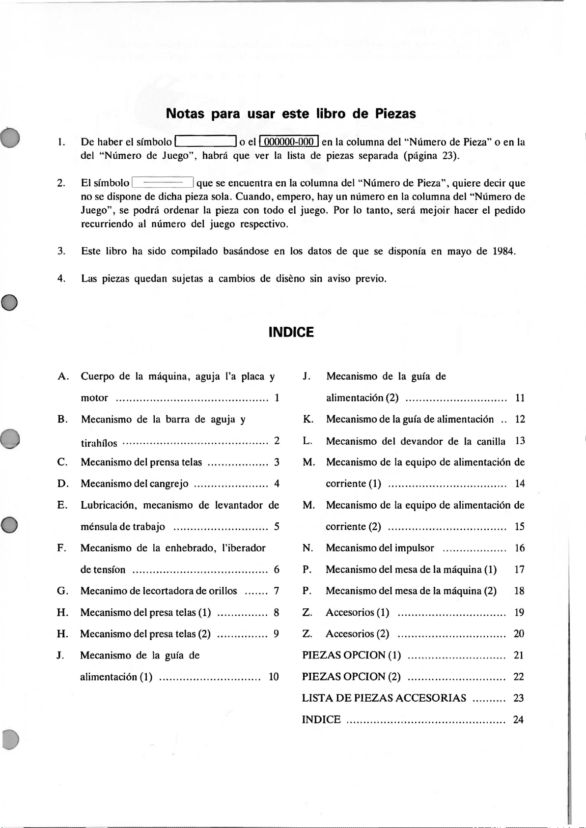
Notas para usar este libro de Piezas
l.
De haber el sfmbolo I I o
del "Numero de Juego", habra que ver
2.
El sfmbolo I I que se encuentra en
no se dispone de dicha pieza sola. Cuando, empero, hay un numero en
Juego", se podra ordenar
al
recurriendo
3.
Este libra ha sido compilado basandose en los datos de que se disponfa en mayo de 1984.
4. Las piezas quedan sujetas a cambios de diseno sin aviso previa.
numero del juego respectivo.
Ia
pieza con todo el juego. Por
ell
000000-000 I en
Ia
lista de piezas separada (pagina 23).
Ia
IN
DICE
Ia
columna del "Numero de Pieza" o en
columna del "Numero de Pieza", quiere decir que
Ia
columna del "Numero de
lo
tanto, sera mejoir hacer el pedido
Ia
A. Cuerpo
motor .....
B. Mecanismo de
tirahflos
C. Mecanismo del prensa tel
D. Mecanismo del cangrejo
E. Lubricaci6n, mecanismo de levantador de
mensula de trabajo . . . . . . . . . . . . . . . . . . . . . . . . . . . . 5
F. Mecanismo de
de
G. Mecanimo de lecortadora de orillos . . . . . . . 7
H. Mecanismo del presa telas (1)
H. Mecanismo del presa telas (2) . . . . . . . . . . . . . . . 9
J. Mecanismo de
de
Ia
maquina, aguja l'a placa y
........................................
Ia
barra de aguja y
· · · · · · · · · · · · · · · · · · · · · · · · · · · · · · · · ·
as
......................
Ia
enhebrado, l'iberador
tension . . . . . . . . . . . . . . . . . . . . . . . . . . . . . . . . . . . . . . . . 6
Ia
gufa de
·.........
. . . . . . . . . . . . . . . . . . 3
...............
J. Mecanismo de
1
2
4
8
alimentaci6n (2) . . . . . . . . . . . . . . . . . . . . . . . . . . . . . .
K.
Mecanismo de
L. Mecanismo del devandor de
M.
Mecanismo de
corriente (1) ...
M.
Mecanismo de
corriente (2) . . . . . . . . . . . . . . . . . . . . . . . . . . . . . . . . . . .
N.
Mecanismo del impulsor . . . . . . . . . . . . . . . . . . .
P.
Mecanismo del mesa de
P.
Mecanismo del mesa de
Z. Accesorios (1) .....
Z. Accesorios (2) . . . . . . . . . . . . . . . . . . . . . . . . . . . . . . . .
PIEZAS OPCION (1)
Ia
gufa de
Ia
gufa de alimentaci6n . .
Ia
equipo de alimentaci6n de
...............
Ia
equipo de alimentaci6n de
Ia
maquina (1)
Ia
maquina (2)
.......... .................
.............................
Ia
canilla
.................
11
12
13
14
15
16
17
18
19
20
21
alimentaci6n (1)
..............................
10
PIEZAS OPCION (2) . . . . . . . . . . . . . . . . . . . . . . . . . . . . .
LIST A
INDICE
DE
PIEZAS ACCESORIAS . . . . . . . . . .
...............................................
22
23
24
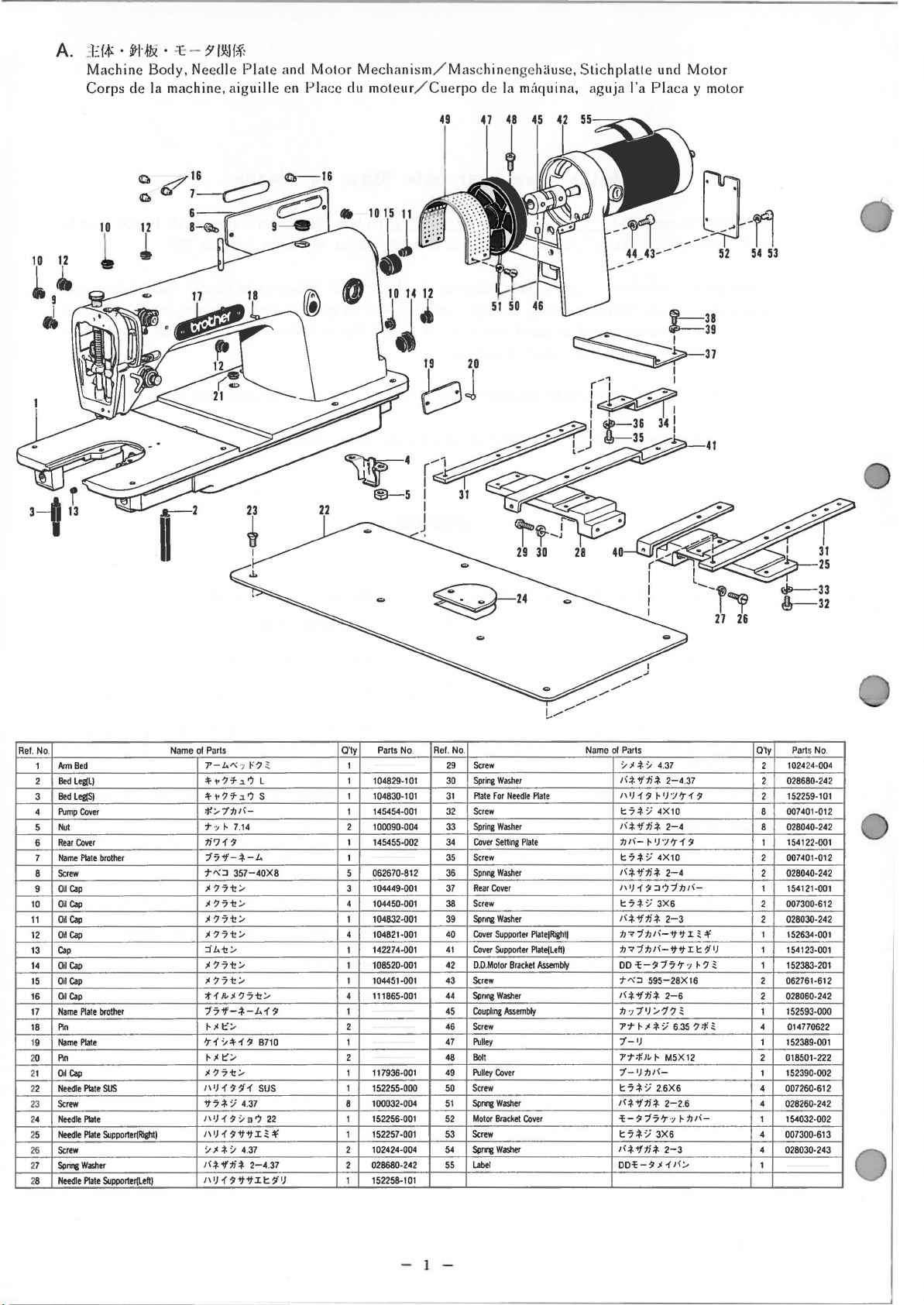
A.
_
l::f,f>:
•
~1-f
Machine
Corps
de
li
·
.:c
Body,
Ia
machine,
-
?'
I~Hf
Needle
Plate
aiguille
and
en
Motor
Place
Mechanism
du moteur/
/ Mas chinengehiiuse,
Cuerpo
de
Ia
mitquina,
Stichplatte
aguja
l'a
und
Placa
Motor
y motor
~4
22
!Jl
®-5
b1
r~'
I
I
I
J
-11
44_
___
43-.-
0-ri
52
54 53
41
I
.......,,..___--""'~
///
______
_,.
..
Rei. No
10
11
12
13
14
15
16
17
18
19
20
21
22
23
24
25
26
27
28
.
1
Arm
2
Bed
Bed
3
PUmp
4
5
Nut
Rear
6
7
Name
Screw
8
9
Oil
Cap
OiCap
Oil
Cap
Oil
Cap
Cap
Oil
Cap
Oil
Cap
Oil
Cap
Name
Pin
Name
Pin
Od
Cap
Needle
Screw
Needle
Needle
Screw
Sp~Washer
Needle
Bed
Leg(L)
Leg(S)
Cover
Cover
Plate
brother
Plate
brothef
Plate
Plate
SUS
Plate
Plate
Supporte~Right)
Plate
Supporter(Left)
Name
ol
Parts
7'-J.."(., !<?
'1'-v?'f,_?
'1'-v?'f,_?
;jl;,']':fJI(-
7
·>
~
7.14
:li?1~
77'1'--t--J..
7":::1
357-40X8
.>1?71:!:..>1?71:!
.>1?71:!:..>1?71:!:.j '
J..i!:.>1?71:!:..><?71:!:.-
:t1
)~)I
77if--t--J,H
~"
t::-
'r1:/'l'-1~
~"
1:':.-
.><?71:!:.-
1\1!1~'11
if7-t-
:/ 4.37
1
1\
1
~
)
111J1~ififi~'f'
:/;I-t-:/ 4.37
J(-1-if:li-t-
1
11
1
~if
)
:.-
?71:!:.-
:/
3?
2-4
if
It
L
s
B710
sus
~
22
.37
!...,....,
.........
Parts No.
O'ty
1
104829-101
1
I 104830-101
1
145454-001 32
100090-004
2
1
145455-002 34
1
062670-812
5
104449-001
3
4
104450-001 38
104832-001
1
104821-001
4
142274-001
1
108520-001 42
1
104451-001 43
1
111865-001
4
1
2
1
2
117936-001
1
1
152255-000 50
100032-004
8
152256-001
1
152257-001
1
102424-004
2
028680-242 55
1
'/
)
2
1
152258-101
Rei. No
29
30
31
33
35
36
37
39
40
41
44
45
46
47
48
49
51
52
53
54
.
Screw
Spring
Washer
Plate
Fer
Needle
Screw
Spring
Washer
Cover
SeHing
Screw
Sprong
Washer
Rear
Cover
Screw
Sprong
Washer
Cover
Supporter
Cover
Supporter
D.O.Motor
Bracket
Screw
Sprong
Washer
Coupling
Assembly
Screw
Pulley
Boll
Pulley
Cover
Screw
5pnng
Washer
Motor
Bracket
Screw
Sp~Washer
Label
Plate
Plate
PlateiRightl
Plate(Left)
Assembly
Cover
Name
ol
Parts
:/"
-t-
:/
4.37 2
1(-t-if:li-t-
2-4.37
1
1
)
)
1\
1
~
~
t:7-t-:/4XIO
1\ -t-if:li-t-
1\-t-if:li-t-
1\-t-if:li-t-
OO'l:-~77'r·>
7 "
1(-t-if:li-t:fJ
7'7
2-4
1
:fJI(-
~
)'/'r1
t7-t-:/
4X10
2-4
1\1)1~:::1?-:f:hl(-
t:7-t-
:/
3X6
2-3
:fJ<-:f:fJI(-ififi ~ 'f'
:fJ7
-:f:fJI(-ifif
:::1
595-28X16
2-6
., 7''J :.-1?
~"
-t-:; 6.
7'-•J
7'7;f.J~
~
t 7
tJI(-
-t-
:/ 2.6X6
17'r·>
M5X12
2-2
3X6
2-3
1
7'-IJ
1\-t-if:li-t-
'!:-~
t7-t-:/
1\-t-if:li-t-
00'1:-~"
'
/'r1
J(;,
~
35
.6
~
~
It
tJJ(-
~
'jl)
~?~
?
;f.~
O'ty
2
2
8
8
1
2
2
1
2
2
1
1
1
2
2
1
4
1
2
1
4
4
1
4
4
1
Parts No
102424-004
028680-242
152259-101
007401-012
028040-242
154122-001
007401-012
028040-242
154121-001
007300-612
028030-242
152634-001
154123-001
152383-201
062761
-612
028060-242
152593-000
014770622
152389-001
018501-222
152390-002
007260-612
028260-242
154032-002
007300-613
028030-243
.
- 1 -

B.
~~-~
·
Needle
Mec
anisme
.k ~ /
Bar
1.\!:lf
and
de
t:
Thread
Ia
barre
10
-·
Take
<\
aiguille
-Up
Mechanism/Nadclstangc
et
10
relcveur
-7
de
fii/Mecanismo
unci
Fadenabnahme
de
Ia barrel
vorrichtung
de
aguja
y tirah'ilos
1
0-s----~~------.,
10-6---Hilll~
15~~
14~
20
~4
nl"
~22
~~~~
~~----~
,-------
I
I
I
I
I
I
I
L-----
~
e e
---
5
~
----
vi
_________
·
~
lt:
I
I
I
1
0
Ref. No.
Upper
1
Upper Sha
2
Upper
3
4
Screw
Upper
5
Screw
6
Puney
7
7-1 Collar
7-2 Screw
Thread T akeUp
8
Thread
8- 1
Screw
8· 2
Sc
9
Thread
10
10-1 Needle
10
- 2
Screw
Cap
10- 3
10- 4
Needle Bar
10-5 Needle
Screw
10-
6
Shaft
Shaft
Shaft
Bush
Take-Up
rew
Take-Up Lever
Bar
Bar
ft Bus
hing(Le
ft)
Bushing(lnterme1ate)
Bushing(Right)
Assembly
Crank
Assembly
Crank
Assembly
Crank
Crank
Rod
Oamp
Name
of
Parts
7?
'/?
7?
'/?
:f.~l~
7?'/?:f.~J~
~
j.
*;;
5.95
??
'J?
:f.~~~
~
j.
*
;;
5.95 ?
'1
- 'I 7'
'/
~? ~
tJ7-
~~-
*;;
63
j.
j.
1
) ;f.
IJ
j.
:.-?
:.-?
*;;
;f.
7?7:.-?
*
;;
??7:.-?
;f.7
*;;
5
7:.-??
7:.-?
6.
35
14
3.
57L
~
'f
3
.57
j-;..t:"
7-:.-t:
~
'/:1-.t. 'J 7.
J''J;f.7v:.-tJ:.-?
J\1J
'/
7~
l\
1\
'/
L 1
M 1
? *
~
A 1
;f.~
~
.>
D·>
t'
O'ty
Pan
147511-001
1
145459-101
140726-000
013760-610
1
145461-101 10-
1
013760-610 10-12
3
118371-001
---
3
100251-001
6
1
159698-001
1
---
2
100251-001
1
104464-001
149313-101
1
1
---
1
145465-001
145600-000
1
145466-001
1
1
111237-001
140004-001
1
s No.
- 2 -
Ref.
No
Thread T akeUp
10-
7
10-
8 S
Be
10· 9
10-10
Fell
11 W1c
Wick
11
Screw
Washer
12
13 Need
14
Needle Bar
Screw
15
16
Needle Ba
Needl
17
Scre
18
19 Needle
Thread
20
21
Scre
W
22
23 Needle
Scre
24
Name
ot
Supporter
Assembly
tud
ann
g
k ? ~ t:'t
le
Bar
Bush~Upper)
Bushing(Lower)
r
e
w
Bar
G01de
Slide
Guide
w
asher
Bar
w
Block
Guide
Pans
7-:.-t::.-~-f't'ti?<
j-;..t:":.-'t'ti
=-
7 I
?.>t:'t 4X4
~
if
J\i);f.')j.
1\
~~-
J\IJ;f.7
.>'//I\
1'~?':1'+
I\
J\i);f-7-f
't7-t.'J
1\
J\l);f-?1':.-1'-f
T"
'J?
-
t'J~--:7''1
:.-'1
J~
~
4X4 1
j.
*
;;
6.35 ? ;f.->
fi-t.
~~~
IJ
;f. 7
:f.
~
)~
0
.t.'J 595 2
'I
OPX5 1
~:1-.t.'J
3.
18
/T
-f tJ?
::J?
~1':.-1'-f
fi-t.
1
IJ
1-f
;f.
::J
77'
4.37
~if
357-40X6
O'ty
1
1
2
1
1
1
1
1
1
1
1
1
1
2
1
1
2
Parts
No.
181429-101
---
147777-000
145624-000
158726-001
158727-001
013781-012
110367-001
111463-001
147326-001
100260-001
145986-001
107415-022
140553-102
102630-001
151594-001
100032-004
146251-001
145688-000
062670-612
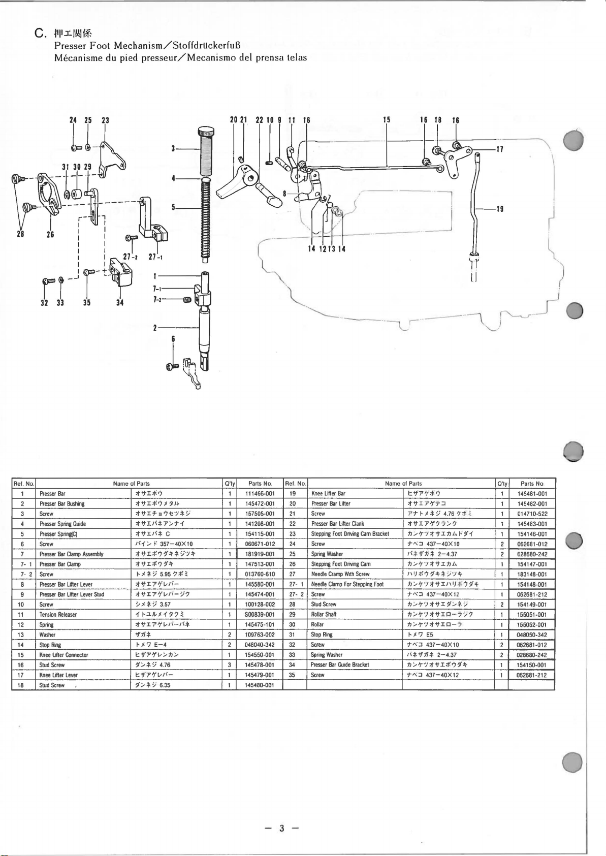
c.
4111.:t.l~1;f:
Presser
Mecanisme du pied
Foot
Mechanism/StoffdrUckerfuB
presseur/Mecanismo
del prensa lelas
l-·1-
··
--.....__
..
--·-,
s
--
__
--·~··
_j
--
If
ll
'-
19
~-·
)
Ref.
Name
of
No.
Presser
1
2
Presser
Screw
Presser
Preswr
Screw
Presser
Presser
Screw
Presser
Presser
Screw
Tension
Spriog
Washer
Stop
Ring
Knee
Lifter
Stud
Screw
Knee
Lifter
Stud
Screw
Bar
Bar
Bushing
Spring
Guide
Spring(C)
Bar
Clamp
Bar
Clamp
Bar
Lifter
Bar
Lifter
Releaser
Connector
lever
Assembly
lever
lever
Stud
1
2
3
4
5
6
7
778
9
10
11
12
13
14
15
16
17
18
Parts
:tifi;f.?
:tifi;f.?"
:tifi'f3'7t!";l-*~
:tifi/(-*
:tifi/(*
1<1
:tifi;f.?~~*:J·;I~
:tifi;f.?~~
~
:tifi7'?'vJ<-
:tif
~"
1
:tif
~~~
7'/71
c 1
/I'
357-40X10
"
*;;
5.
95 ? ;f.;
I
7''tvJ<-;;?
*;;
3.57
~~~~"1~?;
I 1'?'v1<
-1<*
+f:li-*
~,c?
E-4
t:+f7''tv/tJ/
1/-*:J
4.76
l:+f7''tvl'-
1/*~
6.
35
Q'ty
1
1
1
1
1
1
1
1
1
1
1
1
1
2
2
1
3
1
1
Parts
No.
111466·001
145472-001
157505-001
141208-001
154115-001
060671-012
181919·001
147513-001
013760-610
145580-001
145474-001
100128-002
500839-001
145475-101
109763-002
048040-342
154550-001
145478-001
145479-001
145480-001
Ref. No.
19
20
21
22
23
24
25
26
27
27-
2728
29
30
31
32
33
34
35
Knee
Presser
Screw
Presser
Stepping
Screw
Spriog
Stepping
Needle
1
Needle
Screw
2
Stud
Rollar
Rollar
Stop
Scttw
Spri~
Presser
Screw
Lifter
Bar
Bar
Foot
Washer
Foot
Cramp
Clamp
Screw
Shaft
Ri~
Washer
Bar
Bar
Lifter
Lifter
Dnving
Dnving
Wrth
For
Gu1de
Clank
Cam
Cam
Screw
Stepping
Bracket
Bracket
Foot
Name
of
Parts
1:-tfJ''f>t-7
:tifi7'
?'7-:J
.,.
.,.
~"-*;;
4.76
? ;j; ;
:tifi7'?'?7/?
tJ__,Jr
•;J
:tifitJi..
~~1
T"-:J
437-40X10
''
*
+ftJ
* 2- 4.
tJ/Jr"J:tifitJi..
J\IJ;f.71~*~·;~
tJ/Jr•;t:tif
'T":J
tJ/Jr"J:tifi1/*
tJ
/Jr";t
tJ/Jr";l:;f"ifi0-
~
PJ
T":J
''-*+f:li-*
tJ/Jr";l:;f"ifi;f.?~+
'T":J
37
].I\
437
- 40X12
:tifi
0-7 :/?
E5
437-40X10
2-4.37
437-40X12
I)
;j;
.,
'-'
7
1+
Q'ty
1
1
1
1
1
2
2
1
1
1
1
2
1
1
1
2
2
1
1
Parts
No
14548t·001
145482·001
014710-522
145483-001
154146-001
062681-012
028680-242
154147-001
183148-001
154148-001
062681-212
154149-001
155051-001
155052-001
048050-342
062681-012
028680-242
154150-001
062681-212
- 3 -
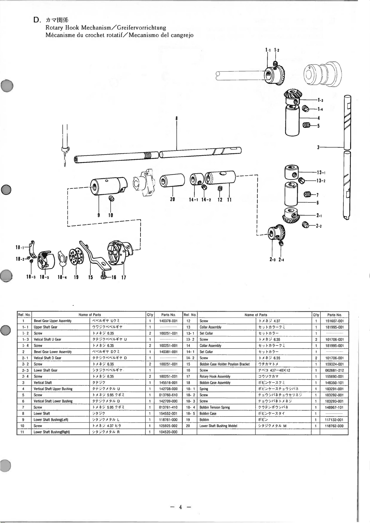
D.
:h
?l~f;f:
Rotary Hook
Mecanisme du crochet
Mechanism/Greifervorrichtung
rotatif/Mecanismo
del
cangrejo
0
.----Pr
I
l
I I
l-----~-~----~
"'i
11-•~f
Re
f. No.
1
1-1
1- 2
1-3
1·
2
2-1
2· 2
2-3
2·
3
4
5
6
7
8
9
10
11
18-3
4
4
~
11-5
Bevel
Gear
Uppor
Upper
Shah
Gear
Scrow
Vetical
Shah U Gear
Sctew
Bevel
Gear
lower
Vetical
Shah 0 Gear
Strow
Lower
Shaft
Gear
Screw
Vertical
Shaft
Vertical
Shah
Upper Bus
Screw
Vertical
Shalt
Scrow
Lowor
Lowor
Screw
Lower
lower
Shalt
Shaft
Bushing(loft)
Shah
Bushlfli(~tl
~
18-4
Assembly
Assembly
~-
~·~
19
Name
hing
Bushing
~
©
}J
1.6
I I '
I
~_j
~~
15
1--1&
of
Parts
-x-xl~'\'"1'
7?:J?
~"*
:;
117:l?
~;<.t.
:f
'X
'X
I~'\'
117:l?
~"*
:;
'l11
:l?'X'XI~'\'"1'
~"
.t.
:J
117:l?
11
7:..
?;1111~
~
"
*:;
117:f?;<111~
~"
*
:;
'l
11 :J?
'l11:J
?;<111~L
~"
*
:;
:..11:/
?;<1111-
17
u?
~
'X'X
I~'I'"I'
6.
35
'X'X
I~'I'"I'
6.
35
"I'
D?
~
'X'X
I~'I'"I'
6.35
6.35
u
5.
95
? ;f,
~
D
5.
95
?
;f.~
4.
37
t:
7
R
U
D
.
®I?
e e
20
O'ly
Parts No.
1
t40378-001
---
1
2
100251-001
---
1
2
100251-001
1
140381-001
---
1
2
100251-001
---
1
2
100251-001
1
145516-001
1
142708-000
1
013760-610
142709-000 18- 3
1
1
013761-410
1
154552-001
1
118761-000
1
125925-002
1
104520-000
~~
~
'
Ill
I I I
14-1
14-2
12
Ref. No
.
12
Screw
Collar
- 1
· 2
1
Set
Collar
Collar
Set
Collar
Screw
Bobbin
Scrow
Rotary
Bobbin
Spring
Screw
Bobb
lower
Assembly
Assembly
Case
Hook
Case
Tension
Cast
in
Shah
Holdor
Assembly
Assembly
Bushing
13
13-1
13-2 Screw
14
14
14
15
16
17
18
1818-2 Screw
18-4 Bobbin
18-5 Bobbin
t9
20
11
PoSition
Spnng
Middel
___
_,
- i
: 6
1
ff
~--
o.
,_,
,_,
Name
of
Parts
~"
*
:;
4.
37
'1!7~:IJ7-?
'I!
·>
~:IJ7-
~;<.t.:.i
6.
35
i!
•J
~:IJ7-?
'I!
·>
~:IJ7-
~"*
:;
6.
35
7'1-:IJ?~;I
Bracket
T'X-:J
43
7-40X12
-:J7'J?:IJ?
;f.
t'/'r-7.?
;f.t'
/'r-}.
'1-
'1-37:.-
J\.t-'1-
'1-37:.-J<.f,
?77/;f.7:,~J\.f.
;!(t'/ 'r-7.111'
;f.
::.-11:f
~;<.f.
I:':.-
?;<111~
~13-1
LJ~,,_,
8-7
~
e-:~~
Q'ty
Parts No.
1
151607-001
"'
~
~
3 7
'lJ\
.t.
3 7:\!';J .f.:f
:J
M
1
1
2
1
1
2
1
1
1
1
1
1
1
1
1
1
1
181995-001
---
10t706·001
181995-001
---
101706-001
159324-001
062681-212
155690-001
148350-101
183291-001
183292-001
183293-001
148967-101
---
117132-001
118762-000
- 4 -
 Loading...