

Page 1
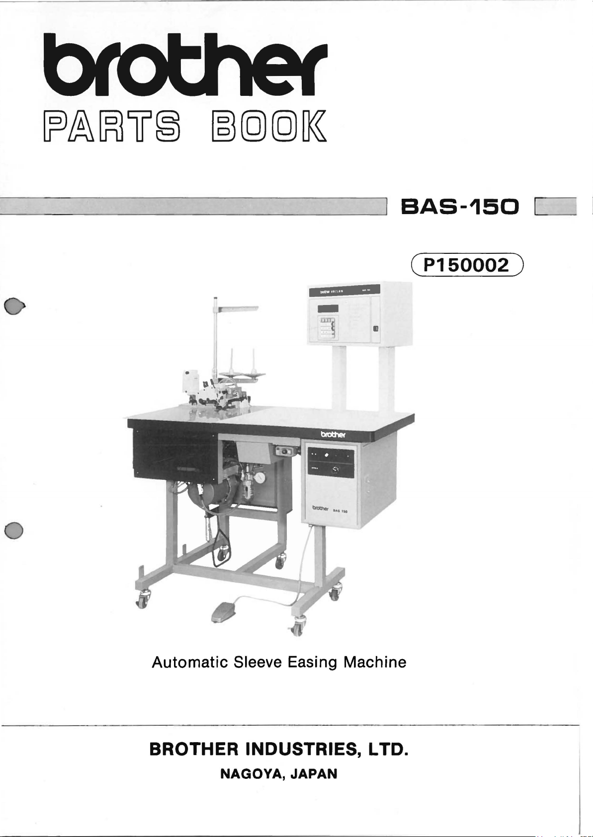
BAS-150
(P150002)
-
II
Automatic
BROTHER INDUSTRIES, L TO.
Sleeve Easing Machine
NAGOYA, JAPAN
Page 2

----
-
----
-
~
0
0
Page 3
Notes for using this parts book
I. If the
2.
3.
4.
symbol!
No."
column,
The
symbol
available for supply. If, however, there
the
parts
assembly
This
book
Parts
arc
refer
I
_______________
can
be
ordered
number.
was
prepared
subject
to
I
is
to
the different
I in the
as
based
changes
found in the
parts
"Parts
an
assembly. Please, therefore,
on
information
in
design
"Parts
list
on
No."
column
is a number
available
without
prior
No."
page IS.
in
column
indicates
the
"Assembly
in
notice.
or
that
the
order
March,
the
"Assembly
Parts
No."
by using
1982.
is
not
column,
the
Anmerkungen zum Gebrauch dieses Stucklistebuches
I. Dieses Zeichen I I in
"Assembly
Seite IS.
2. Dieses Zeichen
nicht lieferbar ist.
steht,
bitte mit dieser
3. Dieses Buch basiert
Modcllanderungen
4.
No.
(Geratesatznummer)"
1---------------1
Wenn
jedoch
kann
dieser Teil als ein Geratetcilsatz bestcllt werden. Bestcllcn Sic
Geratesatznummer.
auf
den
sind
vorbehalten.
der
Spalte
verwcist
in
der
Spaltc "Teilnummer"
in
der
Spalte
Informationcn
"Parts
auf
"Geratesatznummcr"
vom
No.
die
Gesonderte
bedcutet, dal3 diescr Tcil
Marz, 1982.
(Teilnummer)"
Sti.ickliste
cine
Nummcr
dahcr
oder
auf
Page 4
Notes sur l'utilisation de ce manuel de pieces detachees
1.
Si
Je
symbole I I
Ia
dans
pieces annexe page
2.
Le
etre fournie. Si,
Ia
toute
colo
symbole I
piece peut etre
commande,
nne"
Assembly No. (N"
15.
---------------
dans
commandee
veuillez specifier
se
trouvc dans
I
dans
Ia
colo nne "N" de piece" signifie que
Ia
colonne "N" jeu de pees",
comme
Ia
jeu
de pees)", veuillez vous referer a
faisant partie
le
N"
de jeu de pieces.
colonne
il
y a un
"Parts
numero
d'unjeu
No. (N" de piece)" ou
Ia
liste de
Ia
piece ne peut
de nomenclature,
de pieces. Done,
pour
3. Ce manuel a
4. Les pieces peuvent
ete fait d'apres
Notas para usar este Libro de Piezas
I. De
2.
haber
un simbolo I I
columna
separada
El
quiere decir
en
Por
del "Assembly No.
de
simbolo
Ia
columna del
lo
tanto,
Ia
pagina
I~,
que
no
"Numero
sera mejor hacer
les
renseignements valables
Ctre
sujettes a des modifications sans preavis.
junto
a!
(Numero
15.
que se encuentra en
se
dispone de dicha pieza sola.
de Juego",
el
de Juego)",
se
podra
pedido recurriendo a!
"Parts
No.
habra
Ia
columna
Cuando,
ordenar
(Numero
numero
au
mois de Mars 1982.
de Pieza)" o en
que
mirar
Ia
lista de piezas
del
"Numero
empero, hay
Ia
pieza
con
todo eljuego.
deljuego respectivo.
de Pieza",
un
numero
0
Ia
0
3. Este libro ha sido compilado basandose en los
1982.
4. Las piezas
quedan
sujetas a cambios de disefio sin aviso previa.
datos
de que se disponia en marzo de
Page 5
0
CONTENTS
A.
Machine Body .......................... ........................................ .
B.
Needle Bar
C.
Crank
D.
Double
E.
Feed
E.
Feed
Mechanism
Mechanism
Shaft
Chain
and
Lower Knift
and
Synchronizer
Stitch
(I)
(2)
Mechanism
Mechanism
Looper
.......................................................... 5
..............................................
Mechanism
.......................... 2
....................... 3
.......................... 4
............ 6
F. Presser
G. Lubrication ........................................................................ 8
H.
J.
K.
0 L.
M.
Z. Accessories
DIFFERENT
INDEX ........................................................................ ..........
Foot
Chain
Cloth
Air Pressure
Power
Cutter
Control
Supply
Mechanism
and
Threading
System
Mechanism
Equipment
and
................................................... 7
............................................. 9
Control
...................................................
Mechanism
Box
Mechanism
..............................
........
Table Unite ........................................................................
........................................................................
PARTS
LIST
................................................... I5
..
IO
II
12
13
14
16
Page 6
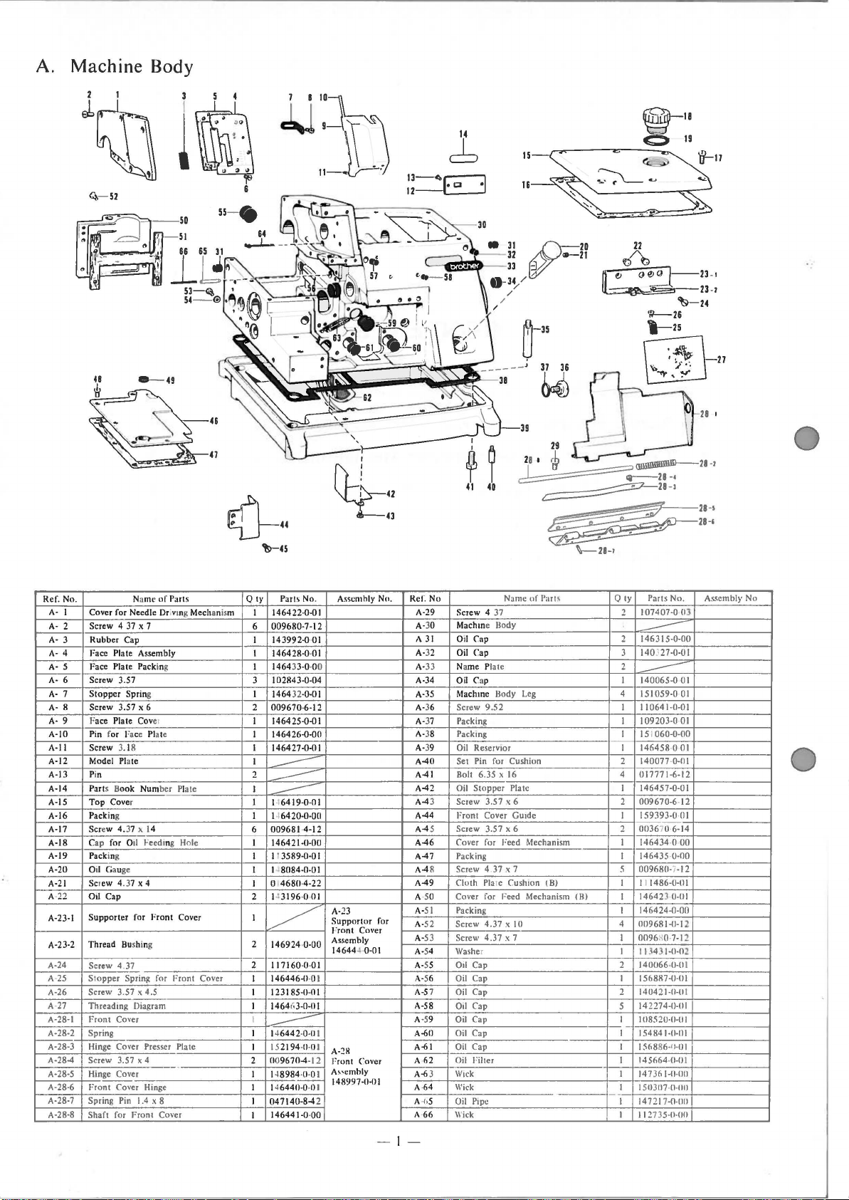
A.
Machine Body
14
c:b
22
~
~23
-
W-26
't-25
~27
~·
23
~24
28
-
1
-I
I
()-
Naml
~
of
Ref. No.
A· I
Cover for Needle Dr ivmg Mechanism
A· 2 Screw 4 37 x 7
A·
3 Rubber Cap
A· 4 Face Plate Assembly
Face Plate Packing
A· 5
6 Screw 3.57
A·
Stopper
A·
7
A·
8
9 Face Plate Cover
A·
A·IO Pin for Face Plate
A-ll
A-12
A-13
A-14 Parts Book
A-15
A-16 Packing
A-17
A-18 Cap for O
A-19 Packing
A-20 Oil Gauge
A-21
A-
22
A-23-1
A-23-2
A-24
A-25
A-26
A-
27
A-28·1 Front Cover I
A-28-2 Spring
A-28-3 Hinge
A-28-4 Screw 3.57 x 4
A-28-5 Hinge Cover
A-28·6
A-28-7 Spring Pin
A-28-8
Spring
Screw 3.57 x 6
Screw 3.18
Model
Pl
ate
Pin
Top
Cover
Screw 4.37 x 14
Screw 4.37 x 4
Otl Cap
Supporter
Bu
Thread
Screw 4.
37
Slopper
Spring for
Screw 3.57 x 4.5
Threading Diagram
Cover
Front Cover Hinge
Shaft for
Parts Q ly Parts No.
Plate
Number
il
Feeding Hole
for
Front
Cover
shing 2 146924-0-00
Front Cover
Presser
Plate
1.4 X 8
Front
Cover
..
~45
22-0-0 I
I 1464
009680-7-12
6
I
14
399 2-0·0 I
I
146428·0·
01
146433-0-00
I
102843-0-04
3
I
1464 32-0-01
2
009670
I 1464 25-0-0 I
I
I
I
2
I
I 146419-0-01
I 146420-0-0Cl
6
I
I
I I
I
2
I
2
I
I 123185·0-0 I
I
I
I 152194·0·0 1
2
I 14
I
I
I
-6-12
146426-0-0()
146427-0-01
----
--------------.
----
009681 -4-12
146421-0-00
113589-0-0 I
8084-0-01
0
4680
-4-22
P 3196·0
01
~
117160
·0·
01
146446-0·0
1464
(.
3-0-0 I
14
644 2·0·0 I
---
()
09670-4-12
8984
·0-0 1
14
6440·0
-0 I
04 7140-8-4 2
146441-0·
00
I
lt-~
42
y43
Asscmhly No.
A-23
Supportor
rront Cover
Assemhly
14644J-
I
A-~8
Front Cover
As<emhly
148997-0-01
O-OI
for
Ref. No
A-29
A-
30
A
31
A-
32
A-
33
A-34
A-35
A-
36
A-
37
A-
38
A-
39
A-40
A-41
A-42
A-4
3
A-44
A-45
A-46
A-47
A-4
8
A-49
A-50
A-
51
A-
52
A-
53
A-
54
A-
55
A-
56
A-5
7
A-58
A
-5
9
A-60
A-61
A·62
A-6
3
A-64
A·h5
A·66
29
28 1
~
rb
~28
(llllllllllllll21
~28-•
-
1
~
~28-1
\--21->
Name
of
Part
Screw 4 37
Body
Mach me
Oil Cap
Oil Cap
Name Plate
Oil Cap I 140065-0
Machme Body
Screw
9.52
Packing
Packmg
Oil Rese!VIor I 146458·0
Set Pin for Cushion 2
Bolt 6.35
Oil
Screw
Front
Screw 3.57 x 6
Cover for Feed Mechanism
Packing I
Screw
Cloth
Cover for Feed Mechanism
Packing
Screw
Screw
Washer I 11343
011
Oil Cap I 156887-IHll
Oil
Oil
Oil
Oil
Oil Cap
Oil Filter I
Wick
Wick
Oil Pipe I 147217-0·
Wick
X 16 4 017771-6-12
Stopper
Pia
3.57 x 6
Cover Gu1de
4.37 .x 7 5 009680-7-12
Pla
le Cush1on
4.37 x I 0 4 009681-0-1 2
4.37 x 7
Cap 2 140066·0·0 I
Cap
Cap
Cap
Cap I 154841-0-01
"'
Leg
tc
(B)
(8)
Parts No.
Oty
107407-0
2
146315-0-00
2
----
140327-0-01
3
2
----
4 151059-0
110641-0-01
I
109203-0
I
060-0-00
15 1
I
140077 ·0-0 I
146457-0-01
I
009670-6· 12
2
159393-0-
I
0036
2
146434·0·
I
146435·0-00
1486-0-111
11
I
146421·0-01
I
146424-0-00
I
0096
I
14042
2
14
2274-0-0 1
5
I
1118520·11-11
1%886-IH)J
I
145664·0-0 1
I 147361-llI 15ll31l7
I 112735-0-
70 6-14
H0-7-12
1-(1-0
1-11-!1
·0·llll
OJ
01
01
01
01
Cll
00
2
1
1
011
1111
00
-1
28-1
As.<cmbly
No
- I -
Page 7
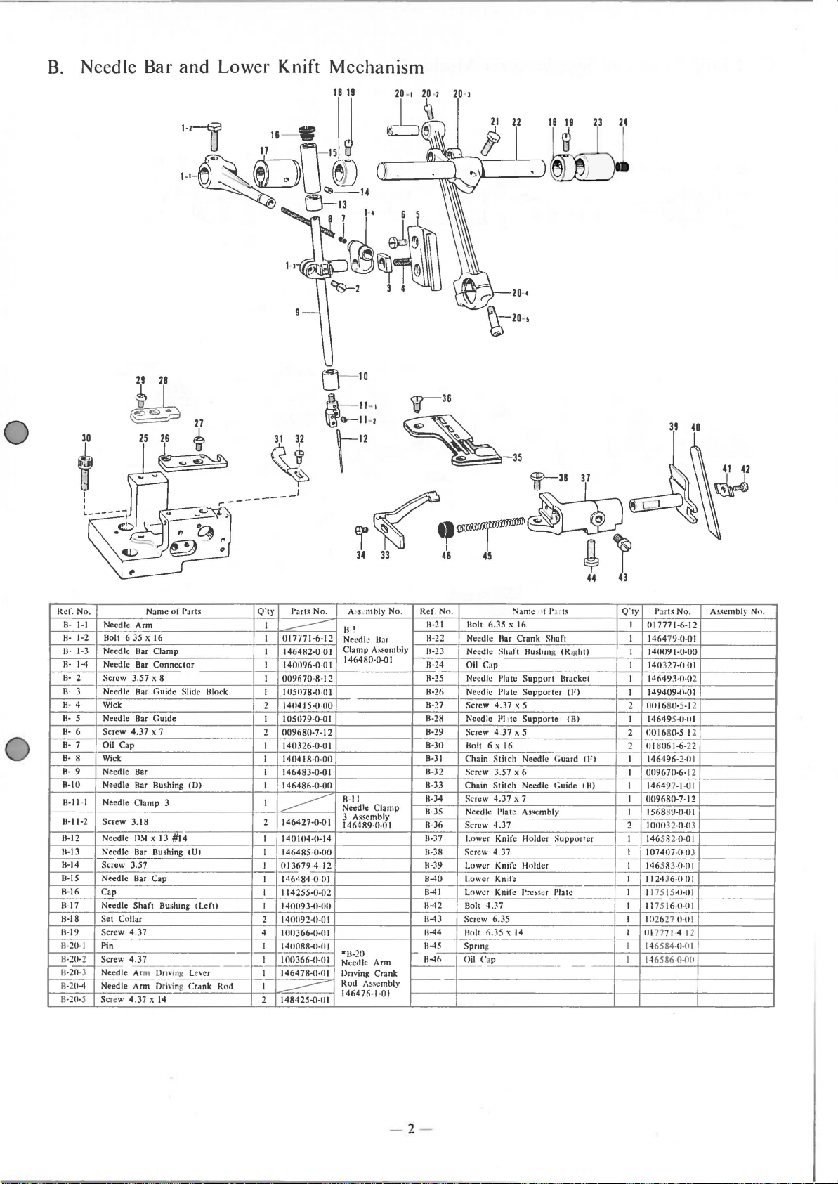
B.
Needle
Bar
29 28
and
Lower
Knift
Mechanism
&k
i
I
I
I
L-----....,
Ref
. No. Name
B-
Needle Arm
1·1
1·2 Bolt 6 35 X 16
II·
Needle liar Clamp
1·3
II·
R·
1-4
Needle liar
II· 2 Screw 3.57 x 8
Needle
B· 3
Wick
8·
4
Needle
II·
5
8·
6
R· 7 Oil Cap
B·
8 Wick
R· 9 Needle Bar
11-10
8-11 · 1 Needle Clamp
11-11·2
8-12
11-13
11-14
B-15 Needle liar Cap
11-16
11·17
H-18
11-19
H-
20·
1
11·20-2 Screw 4.37
8-zOT
8· 2
11·4
B-20-5 Screw
4.37
Screw
Needle Bar Rushing
Screw
3.18
Needle
Needle Bar Bushing tU)
Screw 3.57
Cap
Needle
Set
Collar
Screw 4.37
Pin
Need
le Arm
Needle Arm Driving
4.37 x 14
Ba
r Guide
Bar
OM
Shaft
of
Connector
Gu1de
x 7
3
x 13
#14
lluslung
Dnv
ing Lever
Parts
Slide
(V)
Crank
II
(left)
lock
Rod
Parts
O'tr
I
I
017'171·6-12
---
I
146482-0
I
140096·0
I
009670-8-12
I
105078-0
2
140415-0
I I
05079-0-0
2
009680·7-12
I 140326-0-0 I
1411418-0-00
I
I 146483-0-0 I
I
146486-0-00
I
146427-0-01
2
--------
I 140104-0-14
I 146485 ·
I
013679
-
I
146484·!Hil
I I 14 255-0-02
140119
I
1401192-0-0 I
2
4
I
00366·0-0
I
1411088~1·11
1011366-0·01
I
1-i
146478-0·01
I
..-----
148425-()-01
2
No.
01
·0 I
01
00
0-011
·4· 12
3-()-1111
I
I
A~sL·nthly
8-'
Needle liar
Clamp
146480-0-0 I
I
B·
ll
Needle Clamp
3 Assembly
146489-11·0
•8-20
Needle
Dnving Crank
Rod
Assembly
146476-1·01
No
A.sembly
I
Ann
.
Ref No.
11-39
11-40
11-41
11-42
11-43
H-44
11-45
f-
ll-4h
f----
Bolt
11·21
11-22
Needle
11
-23
Nee~le
11
-24
Oil
11-25
Needle Plate
11·26
Needle Plate
11·27
Screw
11·2H
Needle PJ,,
11·29
Screw 4 .37 x 5
Bolt 6
11·30
11-31
Chain
11-32
Screw
11·33
Chain
Screw
11
-34
11
·35
Needle Plate Assembly I
11
·36
Screw
11-J'/
Lower Knife Holder
11-38
Screw
lower
Lower Kni
Lower Knife
Bolt
Screw 6.35
llolt 6.
Sprong I
Oil Cap
Name •)f Parts
6.
J5
X 16 I
liar
Crank
Shaft
Cap
Bushmg
Support
Supporter
4.37
x 5
te
Supporte
X
16
Stitch
Needle G uard (F) I
3.57 x 6
Stitch
Needle Guide Ill)
4.37
x 7 I 1109680-7-12
4.37
4.37 I
Kmfe Holder I 146 583-0-0 I
fe
Presser
4.37
35'
14
0'1y
Paru N
Shan
!Righi)
Bracket I
tF)
Ill)
Supporter I 146582·0-01
Pia
lc
- -
017771-6-12
I 1464 79-0-01
140091-0-00
I
I 140327-0
14649J-0-0
149409~1-01
I
2
11111680·5-1
146495~1-111
I
00
1680-5 12
2
018116
2
146496·2·11
I 0096711-6-
14649
I
1568
89-IHJI
2 I
IIIHI
32·
107407-011
I 1124 36-0 Ill
I
1
17515
I 1175 16-IH
I 102627
I
111
717 1 4
6584-
14
14
6586
I
39
1-6-22
7-1-0 1
0-11
~1-11
0-11
0·01
0-011
40
Q.
01
2
2
1
12
3
3
1
II
1
12
A"<cmblr Nn .
- 2 -
Page 8
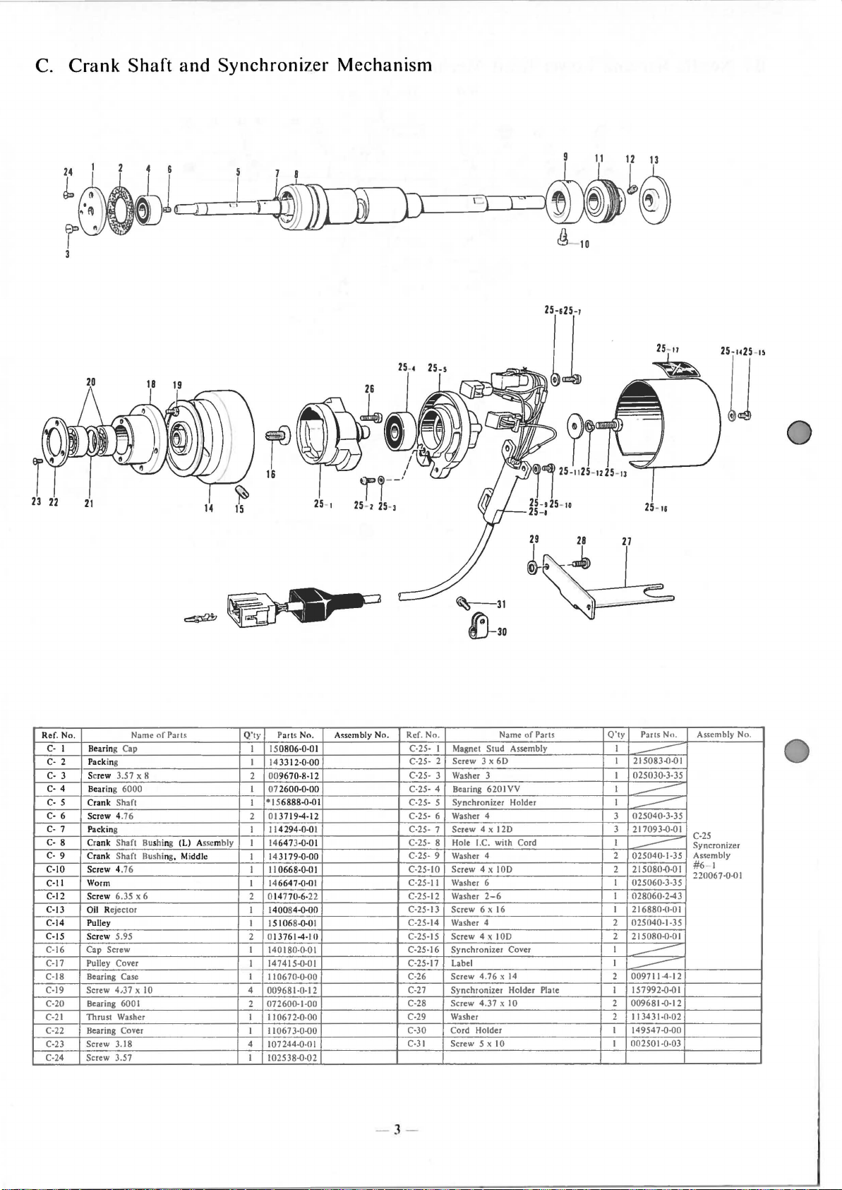
C. Crank Shaft and Synchroniz
er
Mechanism
Ref. No.
C· I Bearing Cap
C· 2 Packing
Screw 3.5 7 x 8
C·
3
4
C·
Bear
C· 5 Crank Shaft
C· 6
7
C·
C·
8
C· 9
C·IO Screw 4.76
C·ll
C·l2
C·l3
C·l4
C-15
C·16
C·l7
C·l8
C·l9
C·20
C·21
C-22
C·23 Screw
C·24
ing 6000 I
Screw 4.76
Packing
Crank Shaft Bushing
Shaft Bushing, Middle
Crank
Worm
Screw 6.
Oil
Rejector
Pulley
5.95
Screw
Cap Screw
Pulley Cover
Bearing Case I
Screw 4,37 x
Bearing 600 I
Thrust Washer
Bearing Cover
3.18 4
Screw
3.57 I 102538.()·02
35
Name
x 6
10
of
Part~
(L) As<c
mbly
Q
'ty
Parts No.
15
0806·0·0 I
I
I
14
3312·0·00
00
96 70·8·12
2
07 2600·0·00
*15 6888{){)1
I
01
37194·12
2
11
4294·0.QI C·25· 7 Screw 4 x
I
I 146473.0·01
14
3179.0·00
I
II
0668·0·0 I
I
14
6647.()·01
I
014770·6·22
2
I
1
400
84.0·00
I 151068.()·01
0137614·1
2
1
140180·0·
147415.()·01 C·25·11 Label
I
-
II
06 70·0·00
4
009681 ·0·12
072600·1·00
2
10672·0·00
I I
I 10673-0.()0 C·30
I
107244·0·
A<Sembly No. Ref. No. Name of Parts
11
01
01
C·25· I Magnet
C·25·
C·25·
C·25·
C·25·
C·25· 6
C·25·
C·25·
C-25-10 Screw 4 x
C·25·11
C-25-12
C-25·13 Screw
C-25·14
C-25·15 Screw 4 x
C·25·16
C·26
C-27
C-28 Screw
C·29
C·31
- 3 -
P3rts
Stud Assembly
Screw 3 x
2
3
Washer 3
4 Bearing 620 I
Synchronizer Holder
5
Washer
8 Hole I.C. with Cord I
9
Washer
Washer 6 I 025060·3·35
Washer
Washer
Synchronizer Cover I
Screw
Synchronizer Holder Plate I
Washer
Cord Holder I
Screw 5 x 10 I 00250 I ·0·03
60
VV
4 3
120
4 2 025040·1·35
100
2-6
6 x
16
4 2 025040·1 ·35
100
4.76 x
14
4.37 x I 0
O'ty
I
215083{)·01
I
----
I 025030·3·35
I
I
---
025040·3·35
--
217093{)·01
3
---
2 215080.0·0 I
I
028060·243
I
216880-<1·01
215080·0·01
2
I
--
0097114·12
2
--
157992.().()1
2 009681.0·12
I
I 343 1·0·02
2
149547.()-00
No.
Assembly No.
C-25
Syncronizer
Assembly
#6
I
220067·0·01
Page 9

0
D.
Double Chain Stitch Looper Mechanism
'
)
__,
I
I
c:tL)- 2
r
--
'i'.'
r.
!
'
'
---
'
'
'
---
·~
---
10
'
'
'
'
___
'
'
'
14
1-1
~
f
(!)
1-1- n
Na
me
of
l,ar
Ref. No.
IJ- 1-1
longetudin
0-
1-2
Screw 4.37 x
Longetudinal Eccentric Cam
0-1-3
0-
1-4
Screw 6.35 x 6
1-5
Boll
00-1-6 Felt
Bolt 6. 35
0-
2
0-
3 Looper Connect ing Rod Stopp er I 146622-0-01 0 -
Screw 3.18 x 4
0-
4
Oil
0-
5
IJ- 6 Longetudin
0-
7 Screw 4.37
Bushing (Rear)
0-
8
Lon
0-
9
Pin
D-10
Bu
0-
11
Chain Stitch Looper
-1
2
0
0-13 Bolt 5.56 x
D-14 Spacer
Screw 4. 37 x 4
D-15
Cap
ge
shi
ng (Fro
Joint
tudin
al Feed
X
16
al
al
14
ts
Rod
14
Feed Cam
Feed Shaft I 146632-0-01
nt)
Holder
Q'ty
Parts No.
I
4 1484 25-0-0 I 0-17
(left)
--
I
2
014770-6-22
---
I
147691-0-00
I
--
017771-6-12
I
009660-4-12 0-24 Feed Lever (Righi) I
I
140327-0·01 0-25 Nut 4.76 I
2
146631-0-01
I
120990-0-11 I
2
I 146633-0-00
I
147318-0·00
I 1
40159
I 1
466
34-0-01
I 149171-0-01
I
148
782-0~ll
111
468
I
·0·
00
0-4-22
A<Sernbly
D-1
Longetud ina!
Feed Rod
Assembly
14661
8-<l-0
Ref. No.
No.
0-16
Double-Chain Stitch
Slide
0-
18
Nut 5.56
0-
19 Feed Lever (Leftl I
Bushing (Left) I
0-20
I
0-21
Longetudinal Feed Lever Shaft I 146628-ll-01
0-22 Bushing I Right) I 140150-0-110
23
Pin
0-26
Bolt 6.35 X
Longetudinal Eccentric Cam (Righi)
0
-27-1
Screw 6.35
0-27-2
1>-28-1
Longetudinal l·ecd Driving Rod
Screw 4 .
1>-28-2
D-29
Washer 4.76 I 153484-0·01
Name
of
Parts
Block I 140313-0·01
37 x 14
looper
16
x 6
Q'ty
Parts No. Assembly No.
14663Hl-OI
I
II
0778~1-02
I
1466311-U-0
146629~1-110
I 146627-11-fll
146626~1-111
1111161-11-116
I 017771-6-12
I
~
2 014770-6-22
I
~
2 148425-0-01
I
0-27
Eccentric Cam
(Right)
Assembly
147988-0-01
0-28
longctudinal
Feed
Dnvln ~
Rod Assembly
146624-1-0 I
- 4 -
Page 10

E.
Feed
Mechanism (I)
l
',
~
0
21
22
L-~~d
29
i3
~
27 26 24 25
30
I
30
1
'
'
"li\~
Ref. No. N:mw
1--
~-
. E-19 Feed
Cover
I
E·
E-
Packing
2
Screw
E· 3
~-
4 Feed
1·- 5
6
E-
7
E-
R
E· 9
HU
E·ll
F-12·1
E-12·2 Differentia
E-12·3
E-12-4
.1
2·5
,,
E-
13
E-14
E·IS
E-1
6
E-17 Washer I
E·IR Nut 4
E·2
11
Shaft
011
Cap
Feed
Shaft
Feed Arm I 146533-0-Cil E-27 Feed
Holt
6.35 X 16
Oil Cap I
Pin I
1-eed
Arm Pin I 146532·0·01
Screw 3
Di
fferential
Differ
ent
H
olt
6.35 X 14
Felt I 147363-0-00
Feed
Main
Rnlt
6.35
Main Feed Link
.76
Shaf
Feed Link I
Main
of Pans
for Feed
3.57
Hushin
.1
8 X 7 2
Feed Adjuster Cap
l
Feed
Feed
ial
·--·
Arm
X 14 I
Hushing
t
Bushing (L)
Shaft
~
(L)
--
---
--
Arm
--
Adjusler I
·----
-
·-
---
-
Clarge)
Shaft
-
!RI
--
~
0'1)"
Part~
I
1401HH-0-04
140IR7-0-00
I
ICI2SJR-0-02 J:-23
3
I 14653H-D-OI
2 140327-0-Ul E-25 Differential Feed Link
I
146539-0-00 1>26
I
017771-6-12
140.126·0·0
14
7J I
1-
009660-7-12
I
I
---
--
I
017771-4-12
--
-
I
-
---
140205·0·0
--
017771-4-12
I 1435
64·0·01
11343
I 143565- 0I 1465
4CHHIO
140209-CHll
Asscmhly No.
No.
I
H·O·OO
E-12
Differential
Feed Arm E-32
Asscmbl)'
146550-D·Cll
1
1-CHI
2
Cll
Ref
. Nn Name
J:
-21
Washer I
t
.:~2
Main
Main
[-24
Differential
Washer I 140208-U-01
E·2R Differential Feed
E·29 Screw 3.57 I 148834-0-0 I
Differential
E-30·1
E-
30·2 Bolt
E-3 1
Packin~
Differential
E-33
Screw 3 57 x
Swilch Lc\'et Plate
c-34
·35
Ongs
(,
L-36
\\
E-37 Screw 3.57 X 6
E·38
t:-39
IACI
E
d'her
Dofterential
Stopper
wa,her
--1
1
Holt 6.
Link Shaf1 ISmail)
Feed
l·
eed
Link
Feed
Lonk
Shaft
Feed Link
6.35 X 14
Gear
12
4
-----
Stitch
for Differential
6.35
35'
14
of
Parts
Bushong
Link I
Bushing
CLargel I
Adjusoing Link
Lever
--
--
----·-·
Control
Stitch
.
---
Control
-· - -
·-·
0'1y
Parts
140208-0-01
140210-0-Cll
I
140207-0-01
I
146554-0-01
146555-Q-01
I
140217-0-Cil
I
146556-0·0 I
I
017771-1-12
I
-----
JOQ203-1HII
I
I 156893·0·01
2
007671·2·12
15691J
I
I 159392-tJ.t•l
-
(125340-2-
I
·-1109670-6·12
I
1----
15689HI-1ol
I
14(•5Cd-O
l
--
0257711·2
2
(117771-4-12
2
No.
-IH)I
.12
·C•
-.12
Asscmblr No.
E-30
Link Lever
A'<embly
146914·0·0
I
I
- 5 -
Page 11

E.
Feed
M h .
ec
amsm
(2)
78
50-14
SO•i
~
5011
~
50-11
~
5019
~
50
60
'
'
56~
61
-•
57~
'
'
'
'
'
'
L~·
72
',,,g:--75
'•,,
~,.
oo
~77
'
·
~
69
~
'
'
~
66
68
-
Ref.
Nn.
l
E·50·
ffi§
. Name
l·ecd Rod I'
E·50· 1 S rc\Scr !'late l)' l'all> No. 1
. - • crew ] .
L·50· 4 Need)" R I 117517·0·03 l E·57 l . Name ol
,_
,,_
' ''
'"'
,_,_
. 'I ,,.. '-" 1
E·50·
~
,
__
,,"
'
_,_
,_,, ·.
E·51HO Spring-Vhecl
E·51H I Wasllcr ---144053-IHll 1_,·><>
E-50·12 St
,_,_,.
,,_,_,
. .
H<H•I
'.
'"" '
I
E·50·17l
,.,>Oi/
E·50·19;-r
E·51
--::-:-...:..:.'.L: '·'.':"'""'
-;:--::""-~
I-E·53
E-54 1 spnng -1
t
1--~':-:-
' ·.,.5_2
_l,_:_:
1-
-;-::-:--1-..:.
~'·"
E·56 1 S
1--
__
""'
' ,. ' .
(,
1 s.ccentnc Wheel - I I
' . - c
"
;'~"""
'""
9 l:cccntnc
"'
"
'"""
''"
"'~·
~
..
"'"
" ""''
G"
,:
.h
oldc~
'' Holder
CO
s'~'
Holder Plate lSI
l p k' · '
.._.acc.m
g
-~
.
w
~a
,.
s
h.c
r
·:..:.
~"1'~
Ring 1 1
5
l , .
...,
AdJU
1
__,_.::_·
:!up~pmor
nfl'all'
38
"""'
..... , '" '
"''~'
'-"
~
. 1 144055·0·01
..
J 0 "'
''
. l
..
w '
-p·l
"'
' " . o
5
. """"'"'
Si ing Shafl
~d
ter
fnr 1.-
_ 1 A
""""
Adju>tin ~
_ 0 W
<Co
o • M t
Ad
JuSiin•
C
===r
Q'
I ,
'"'
""'"
"""·""
~
~'""'
0
I ' -I
'"'"
-
.-=':-:----
,.:;;;-
-'-
' I .,;. L
1
0 0
m"
'II 1 100025
1
"c
mhly No.
'""
1
-!1·02
1
\\~tccntnc
""·04
1
"'·"-'"
'"
'
...........
I
I4040HI·I
1 - Diffcrcnllal I' d I I I
- -
----
~~_I
Sl
.
1
""'"'"'
~
~
-
'
146~1
-'
141l403
•=
I - ·=
1
-~
I IR
771HI·O
1
1134
I I I
""'""
1
048
0411·
I I· ragme 1 ;;;-;;.,.-:-_.:.:..L_
""'""
1465
1 J
14
1
O<mO<O<H
' '
""'"'
""'
"'.,-j
'
81 F-67 I
1
·1H
II
I
3
----II
1~
1--
""
~
=~
342-
'
J6·11·III
"''· ""
l
L
1--
-·
I--E·61
' ,
~;-62·
0"
~
1
!-'
~
1---"i.!
>---'= "'"''"' 0
~-":"-
I E-78 I
--t
- 6 -
I
,_,.
I
,,
••
•
;.,
l
····-
iTo-
'-<><>·
iT
r•
:, """ '''"' ""
'
O·
31
,.
.•
' 0 ; <
2 Scr"W '
"'
,.
' I "'"' ' • ' _,
C.
,; 8 I llnll 4.37
E711 1 ,,
'" I '
E·72
_lFccd
F·73 J llar <.uidc ILl
1:-15
""'
E·77 nt Proteclor Plate _149886·0·111)1
,_,
,,,..
,_,
~····
""'
"'
'""'
"' ,.,.,
Feed L'f · F
'oObo 0
l'e d 1 tmg Shdc Rinck _
"''
,-5
I Screw ar (,uJdc llluck Shafl
I , • .;;-,
....
"'
' " '
1
".
'am
Feed llug
ar GuJdc
""
,.
'"'"
.•
J
'"~
' n ' -"80±":!" I -
"'"
,_,
l~an
.
Screw 3.5
~emcnl
Screw 6.
35
brl<
' '
1
,
.
G<>;o<
--
0 0
~
~
'"""''
I'
7
~
,.,
----1
"'~'
'"'
CR)
--
-·
0
,.,
I
'""
·~·
J o-6·12
'
I'"""
' I
' I
--+--,
_ I I
0 j 0
I I ·0·00
H-
I ' ,_
OJ
-
jD_i:oi'l4i77::j7il.lt·:i6
.
'"""'
'"'
""""''·'.'
~:..t
0«547
"""'
""
101706-0·01 •,:::liar Asscmhlv
-
~1~
"'"
"'""
~~147362·0-~~-+
----<--0
=r'
------;-
O<O,.HH"'
0
1 1
,----.-:,5;;--;ll:--:8~.::...::~--t'-
-
~16·0·01~-
>---;-"
___
,_,
"o
0
1
13
- "
0
08
113431-!Hill
-
~loo7.74i'ini77j.
~.
2
_,_'"
•
1-1174117-0-03
1
1
-1
- I 116568-IHIJl
1])-;-;-;;-;-;:-:-:.:..::.:~'L
I
llllli251-0·0il
~
"
·••1
113431·1Hf1
149887-U·Oi'
"
'"'"'"''""·'
il
,
·
~cd
11141<6>ck
1
1
ni96•J.()()]
t-
----=~i
I
II
o
,H--
,----=~
>'
_-
-
-
'I
I
--;
---
60
54J.IHII
liar Gu'd
A»:m'hl~
--=---
.,
_1
-
_
·1
I
Page 12

F.
Presser
Foot
Mechanism
32
- t
Q--27
®---28
Rer. No. Name
F- I Presser
Presser
F- 2
Stop
3
F·
F·
4 Washer
F·
5 Presser Bar
F·
6
F- 7 Screw
F·
8
F·
9
F-10
F-11
F-12 Presser Arm Shaft
F-
13
F-14
F-15 Collar
F-16 Bolt 6.35 X
F-17 Presser Foot Lifter Inside Lever
F-18
F-19 Bushing (Righi)
Ring
Spring
Presser
Spring
Main Presser Arm
Pin for Presser Arm Shaft
Screw 4.
Bushing
Stop Ring
of
Bar
Bar
Bar
37
Parts
Lifter
Lifter Pin I 144084-0-0 I
Shaft
Lifter
x 4
16
Q'ty
Parts No.
I
147759-0-ol
048020-3-42
I
I 144083·0-01
144085-0-0 I
I
I 144086·0·01
144079-0-01
I
I 146521-0-01
I 144081 ·0-0 I
146526-0-01
I
I 146527-0-01
1465 25·
I
I 014680-4-22
140263-0-00
I
140261-0-01
1
017771-6-12
1
I 1465 24-0-0 1
1
048080-3-42
140262-0-00
I
32
L"
Assembly No . Ref. No. Name
0·0
I
F-20
F-21
F-22 Screw 7.94
F-23
F-24
F-25 Adjuster
F-26 Screw 4.37 x 7
F-27 Screw 4.76
F-28
F-29
F-30 Screw
F-31
F-32·1
F-32·2
F-32·3
F-32-4
F-32·5 Pin
F-32-6
F-32·7
Cfi-32-l
-5 32-4
~32-5
Presser
Fool
Plale
Arm
4.
76
37
er Foot
2.38 x 3.5
Lifter Link
Stopper
x 7
Arm
(31
Pin
Presser Fool Lifter
Spring
Nut 4.76
Presser
Screw 4.
Sub-Presser
Spring
Screw
Press
Chip Guard
Screw
of
Parts
Lever
Q'ty
I
I
I
I
I
I
2
2
2
I
I
I
I
I
I
1
I
1
I
25~~
26~
Parts No.
146523-0-0 I
110793-0-01
148372-0-01
143323-1-03
14
33
25-0-0 I
146522-0-01
009680-7-12
153483-0-01
110161-0-06
144088-0-01
I 07231-0-02
009680-7-12
142246-0-01
--
01
142247-0-
142243-0-00
--
142245-0-01
009639-3-
12
(!t
Assembly No.
F-32
Presser J-oo
Assembly
156891-0-
t
01
- 7 -
Page 13

0
G.
Lubrication
16-t----tf
16-l------G:)
16-l-(1
0
Ref. No. Name
G· I
G- 2
G- 3
G- 4
GG- 6
G- 7 Oil Feeding Pipe
G· 8 Packing
G- 9 Vinyl
G-10
G-Il
G-12
GG- 14
G· IS
G-16-
Packing
Oil Feeding Pipe
Main
Oil
S
Screw 3.57 x 6
Vinyl
Packing
Vinyl
Oil Feeding Pipe (B)
13
Packing
Screw
Pin
Screw 3.57 x 8
I
Oil Pipe
Cap
Tube
Tube
Tube
of
Part~
(8)
(8)
i--14
O'ty
Part•
No. Assembly No.
112348.{).{)(
2
112364.{)-01
I
146636-1-01
I
140325.{)-01
I
009670·6-12
I
I 1407 80-0-0 I
112364.{).{)(
I
112348.{)-01 G-16-
2
I I
56897·0-0
112348.{)-01 G-16- 7
2
I 140778·0-01
112364.{)-01
I
112348.{)-01 G-16-10
2
I 112359.{).{)1
147318.{)-00
I
009670-8-12
I
I
G-16 147521-0.{)1
Ref
. No.
G-16- 2
G-16- 3
G-16G-16- 4-2
G-16-4-3
G-16G-16- S
G-16-
G-16- 8
G-16- 9
G-16-11
G-17
G-18
Wash
Worm Wheel
4-1
Pump
Pump Inner
Pump
44
Pin
Pin
6-1
Collar
6·2
Screw
Pump Case
Pump Cover
Oil
Filter
Oil
Filter
Screw 3.57 x 10
Screw
Pin
D3x
er
3.5
Inner
Outer
6.35
4.76
16
Name
Rater
Rater
Rater
Gauze
Frange
x 12
of
Parts
Shaft
Q'ty
Parts No.
025350-3-32
I
144619.{)-00
I
I
I
--
I
--
I
--
144622.{).{)1
I
--
I
I
01706.{)-01
2
---
I
147527.{).{)(
I
--
147528.{)-00
I
147529.{).{)1
I
3
009671-0-12
2
009711·2-12
508693-0-01
2
Assembly No.
G-
16
Pump
As.sembly
147521-0-01
G-164
Pump
Inner
Rater
Assembly
147523-0-01
G-16
·6
Collar As.sembly
181995-0-01
yl
- 8 -
Page 14

H. Chain
Cutter
and
Threading
rr
1t1l
1 s
~1-11
~-~·4u~~-~~
~
1-
14"""1!1
1-u
t=;_::
3t-C>A..
31~~"Q
3-4
3-s
~~
~r28~~
29
30
~;;
-T
27
\
I
~
r~
1 a 9
26 25
~
~"f
31
32
6
.
~3-1
~+z
:
'J
'
··
..
~(f'(frb~
15
u,....~'T
17
18
24 23
~
I
:J
Clf
42--9
~
45~~~
t,~
~
:~·
~~42
-=
~
'
~
T "
47
48~
~?
49
50
19
44
43
~!~
51~
·
"
~,
~
l0b
~
20
I
20
l
'f-52
Ref. 'llo.
1-
H
H-
1-
H-
I·
H-1-4
H-
1H-
I- 6
H-
I- 7
H-
I- 8
H-I-
I-10
H·
H-
1-11
H· 1-12
H-
I-I3
H-
1-14
H-
I-15
H· 1-16
H-
2
H-
3- I
H-
3- 2
H- 3- 3
H-
3- 4
H-
3- 5
H· 3- 6
H-
3- 7
3· 8
HH· 3- 9
H-
3-10
H-
3-11
H-
4
H-
5
H-
6
H-
7
H-
8
H
9
H-13
H
14
H-IS
H-16
H-17
4.37
Stopper
Plate
ing
Bar
5.95 X 16
g
Ring
18
Cutt
pe Cutter
Thread
Thread
Thread
Di<~:c
Nam o Parts
Assembly
x 10
er
Bracket
er
Low
x 4
er Shaft
Upp
5
10
I
Solenoid Cover Assembly
2
Washer
3
Screw 4 37 x 10
Solenoid
5
Screw
Solenoid Bracket
Plunger
Stopper
9
Screw 3.57 x 6
Spr
Guide
Screw 4.37 x 4
Guide Plale
Nut 8
Rack
Felt
Screw
Pinion
Screw 4. 37 x 4
Washer
Spnn
Stop
Tape Cutt
Tape Cutt
Screw 3.
Tape
Ta
Screw 3.57 x
Screw 3.57 x
Needle
Screw 3.57 x 6
Needle Thread Guard
Needle
Screw 3 18
Thread Guide
Looper
Felt
Tension
Presser for Tension
er
Blade
er
Blade
Guide
Gu1de Spring
Supporte
Tension
Control
DISC
Q'ty
Pats
I
149492 0 01
113431-0-02
2
009681-0-12
2
147364-0-01
I
4 009681-{]-12
149491 I
I
5 I 5
88
I
2
14
7390-{]-01
I
009670-6
3
I
149789-0
I
I47
393 0
O
I4680
I
I
147794-0-0I
4
I 4
7986·0·0
1473
91
I
14
7916-o-
I
0
09761·6-12
2
I
147403·11·01
014680-4-22 H-33
2
147792-0-01
2
149394-(]-01
I
I
147401-0·0
I
I
147405-(]-0
--
009660-4
2
I
I 153031-0 0 1
----
2 009670-5-12
009671-0-12
2
I 14 7344-0-0 I
I
009670-6-12
I 112300·0·01
I
112299-0
I 112301
146649-{]-0 I H-49
I
Stud
I 110820·0·01
I 110832-(]-01
2 145446-0·01 H-52
144103
I
Assembly No
No
01
·0·00
Il-l
Solenoid Drivmg
Mechanism
I 2
Assembly
I49790-0-(]l H-24
OI
OI
4-22
I
0-0I H-29
oo
H-3 H-36
1
Tape Cutt
A
ssembly
149392-(]-(]1
1
-12
01
II
01
002
Nut
Guide I
GUide I
Q'ty
Parts No. Assembly Nn.
144104-0
01
144105 0 00
149566-(] 01
I
147049·0·03
I
I46648
0-01
014770·6-22
146656
I
I
I
I
I
I
I
I
2
I
I 147148·0·111
I 146663-0-01
2
I
I
I
I 150812-0-01
I 11281150-2-42
2
I
0-01
ISI617·0-0I
009670-6-12
146925·0-0I
009670·6-12
143757-0-01
0119660-4-1 2
146650·0-01
009670-8-12
151012-{]-01
144105-0·1111
145446·0·0
110832·0·0
I
511808-(]-0 I
11016311-4-02
I 5081
O~Hll
0096711-4-12
150811-0-01
15!1813·0·(11
014680-4·22
146930
0 01
6-12
H-20
Thread
Control
Assembly
149568·0-03
I
I
Tension
Nut
Name
of
Ref. No.
11-18
Spnn
II 19
H-20-1
H-20-2
II 21
11-22
H-
23
H-25
II 26
H-27
H 28
H-30
H
31
H-32
H-34
H-35
er
H-37
H-38
H-39
H-40
H-41
H-42
H-43
H-44
H-4'
H-46
H-47
H-48
H-50
H-51
g I
Ten
sion S
Thread Tensoon Adju
Tensoon Indicating Plate
Main
Thre
6.35 x 6 I
Screw
Thr
ead Guode
Screw
3.I8
Chain Stltcl!
Screw 3 57 x 6
Thread
Guide
Scr 3
57
Needle
Thread
Screw
3.18 x 4
Cham
Sutch
Screw
3
57
Upper
Thread
Tension
Spnng
Thread
Tension Adju<ting Spring I 147149-0-01
Tension Disc
Felt
Thread
Tension
Needle Thread Gu1de Plate I 110813-0·111
Chain
Stitch
Thread
Guide
Screw
2.38
Thread
Handler
Screw
3.57
Thread
Guide
Screw
4.37
Washer
2-5
Spring I
Chain
Sutch
Screw
4.37
Thread
Guide
Screw 3.57 x 6 I 0119670-
Parts
pnng
Washer I
Ung
ad Guide I
P1pe
x 6 I 0 13660-6-1 2
Looper
ThreJd
6 I
(A)
Gu1de
Needle
Thread
x 8
Tension Adjusting Screw
Washer
Control
Slud
Looper
Base Plate I
(R)
x 4
x 4
CL)
Looper
Take-up I 150807-1)-(11
x 4
-9-
Page 15

J.
Cloth Control
1-•
-&
1-2
~
1-l
~
1-4
--El
~-i:iJ
•
~"-
• -
·~
~
1-~
',
1-a~
,1·!~
;.;
~
~
-t
~-
:
I
2
~
Sys tem
and
J
15
-·
-
I~,
,_,.,_,
,
~15-1~15
-
2
,6~
1-12
r-~
~
1-
u •
~1-14
--~~~
~
Control
Box
16~
I •
1
:::='
~~
•
•••
--;. I
••
Mechanism
15-4
~
20-a
w~
2~~
-
CJ:>(j}_~-i
"'
20-u
I
~lO-a
~20-1
0
Ref
. No. Namr
1-
1·
I
111111·
11·
1·
11·
11· 1·
1111- 2 Washer
111· 5
1· 6
11· 8
1·
1·10
J.ll
1-12 Washer 4
1·13
11-15·
J.l 5-2 Syncronizer Cord
1·15· 3 Orljllnal Point Cord
Thread
Tension Spring Washer
I· 2
Spr
I· 3
Pres
I· 4
I·
5
Looper
Presser
I· 6
1-
7
Li
Roller S
I·
8
1-
9
Servo
1-
10 Pin
HI
Stop
1-12
Roller Shaft
Be
1-1
3
Slop
14
Presser Pta te
1·15
Sh
1·16
1-11 S
top
3 Was
4
Bo
Servo
Washer 6
7
Washer 2 6
Bah
Servo
9
Servo Roller
Screw 4 x 5
Washer 2 4
Screw 4 x
14
I
Control
mg
ser
fting Plate I 149372
Ring
aring
Ring
aft
Rmg
he
r 2- 6
lt 6 X
6 X
of Part
Ten
sion Adjusti ng Nul
for
Tension Di
Thread
Tension
Plate
upporter
Presser Roller
Ba'\e
14
Motor Sett
10
Motor
14
Board
Circuit
ing
!'l
s
sc
Control Stud
ate
O'ty
Part'
1495n6-0-0I
I
144105-0-00
I
I 1441 04-0-0 I
144103-0-02
I
I 110820-0-01
I 15691 5-0·0 I
I 149368-0-01
I 149367-0·00
I 149371-0·01
048020-3-42 1·20- 4 Power
2
149369·0·01 1·
I
2 149489-0·0 I
048020-3-42
2
I
149373·0·01
I
149374-11-0
I 048040-3-42
2
0~5060·2·32
2 112H060·2-42
01806 1-4·22
2
I
149364·0·01
2
025060·2·32 l-20·15
2
028060·2-42 1·20·16
2 0 18061·0-22
I 149179-0·01
I 149366-0·01
2
1114400·5-22 1·
4
025040·2-32
4 028040·2-42 1·23 Washer 2 4
4
00240 1-4·02
I
156921-0-01
I I 56924-0·0 I
I I 580 16-0·0 I
A«emhly
No.
-{1
·01
J-1
Servo
PresNer
Assembly
156914·0-01
I 1·20· 9
1-15 1·25
Operation
Assembly
I 56920·0·02
No .
Box
1·201-20·
1-2Q-12
1·20·
1·20·
l-20·17
1·20·18 Valve
1-20-19
1·22
1·24
1·
1·
Ref
. No Name
1-15- 4
1-15- 5 Power
1-15- 6
1-16
1-11
1·
1-19 Nut 2
1-20· I
1·20· 2
1·20-
1-20·
1·201-20· 8 Washer 4
18
3
20
· 5
6
7 Cover A
10
11
13
14
21
26
21
E
arth
W1re
Pulse
Motor
Screw
Washer 6
Washer
Con
trol Box
Panel Plate
Volume
Rubber
Cover B
Screw 4 x
Mounting
Cloth
Sensor
Contr
ol Circuit Board
Collar
Washer 3
Washer 2
Screw 3 x 30
Harne" A sembly
Cord
Mot
or
Tran
sfotm r
Washer 4
Screw 4
Washer 6
Wash
er
Roll 6 X
B
Supply
Cord
6 x
40
2-6
Adjuster
Supplr
Bush
10
Plate
3
LeJd Wire
Box Assembly
'8
2 6
10
Cord
Cord
of
Parts
O'ty
I
I
I
8
8
8
8
I
I
I
I
I
I
I
10
10
I
I
I
6
6
6
6
I
I
I
I
2
2
2
2
2
2
Parts No.
156927-0-01
156925-0-01
156923-0-01
149320-0-01
025060-2-32
028060·2-42
021060-1·02
I 56902-0·01
--
149932-0·01
149900·0-01
14990 1-0-0 I
149559-0·01
149558-0-01
151592-0·01
00240 1·0-03
149556·0·01
149937·0·
159593-0-01
149560-0·
01
025030·2·33
0280
30-
2-4
3·
0·03
00230
15
3328-0·01
I 57993·0·0 I
01
149990-0
I 50493·0·0 I
025040-2-33
028040·2
-4
002400·8·03
025060-2·32
-4
028060·2
1-
0·22
01806
01
3
3
2
1-20
Control
Assembly
Assembly No .
1-15
Operation
Assembly
I 56920-0-02
Box
Box
-10-
Page 16

K.
Air
Pressure Mechanism
jJrs7
25
of
Ref. No.
Cylinder
K· I
2 Connector
K-
Stop
3
K·
K-
4 Piston Rod
5 Pin
K·
Tension
K·
6
K-
7
Nut 6
Spring
K·
8
Boll 4 X 8
K-
9
Washer
K-10
K-
11
Cyhnder Bracket
K-12 Washer 2- 6
K-13
Screw
K-14 Swttch Plate
K-15 Boll 4 x 8
K-16 Switch Panel
K-17 Sticker
K-18
Pin Lever Valve
K-19 Air Cock
Connecto
K-20
K
-21
Limit Swit ch Plate
K-22 Boll 4 x 8
K-23
Wa
K-24 Nut 4
Air Cyl
K-25
K-26
Elbow 4
K-27 Air Cylinder 30 X 200
K-28 Nut
Joint
K-29
K-30 Pin
K-31
Elbow 4 • PT
K-32 Rod Connector
Washer 6
K-33
K-34 Washer
K-35 Boll 6 X 20
K-36
Pin Assembly
K-37 Safety Sticker
K-38 Screw 3 x 5
K-39 Air Pipe (AI
Name
Ring
Joint
Disc
2- 4
r
sher 4
in
der 20 x 25
• PT 1/8 • BS I
Assembly
1/8-
2-6
PariS
BS
Q
'ty
Parts No.
152226-0-00
I
149435-0-00
I
048040
I
14941 1-0-01
I
146153-0-01
I
145446-0-01
I
021060
2
I
I
52230
018400
2
028040-2-42
2
I 51735-0-0 I
I
028060-2-42
2
2 140620-0-0 I
153255-0-01
I
0 18400-8-22
4
I
I
----
153256-0-01
I
----
151093-0-01
I
149506-0-01
2
149341-0-01
I
018400-8-22
. 2
025040-2-32
2
021400-2-02
2
153032-0-01
I
149503-0-01
I I 53253-0·01
149488-<1·01
I
149501-Q-01
I
151177-0-01
I
14950J.<I·OI
2
153254-0-01
I
025060-2-32
2
028060-2-42
2
018062-0-22
2
151178-0-01
I
I
I 014300-5-22 K-68
----
153259-0-01
I
Assembly No. Ref. No.
-3-42
-3-06
-0-0 I
-8-22
K-65
K-66K-66K-66K-66K-66K-66K-66K-66K-66K-66-10
K-67
K-69
of
Parts
K-40
K-41
K-42
K-43
K-44
K-4
K-46
K-47 Screw 5 x 10 2
K-48
K-49
K-50 Elbow 4 • PT
K-51
K-52
K-53
K-54 Spiral
K-55
K-56
K-57 Air Tube
K-58
K-59
K-60
K-61
K-62
K-63
K-64
Air Pipe (B) I I 53262-0-01
Washer
Nut 5
Bushing
Air Pipe
5
Washer 5
Washer
Cylinder Assembly I
Connector
Pin
Piston Rod Joint I
Stop
Bead Band
Air Tube 4 x 2.5 I I
Air
Washer 6 2 025060-2-32
Washer
Boll 6 X 8 2
Air
Air Connector I 149434-0-00
Air
Cap I
I Solenoid Valve 5 149508-0-01
2 Valve Mounting Base
3 Elbow
Adjusting Valve
4
Name
2-5
Supporter
2-5
1/8-
BS
Rin1
Tube
6 I 149801-0-00
Unit Assembly I
2- 6 2
Tube
I 0 x 6.5 I 149514-0-01
Joint
10-
PT 1/4 I I 5 327 3-0-00
5 Bushing
6 Cap I 153274-0-01
7
Silencer
8 Air
Joint
9
Air
Elbow 4 • PT
Bolt4xl0
Washer
Washer
PT 1/8 I I 51620-0-00
Joint
4 · PT 1/8 3 149435-0-00
1/8-
BS
2-4
4
Q'ty
2 028050-2-43
2 021500-1-03
3
I 153257-0-01
2 025050-2-32
2
I 149435-0-00
I
I 146153-0-0 I
I 048040-3-42
24
I
I I 5 325 2·0-00
I I
2 153268-0-01
2 I
2
2
4 018401-0-22
4
4
Parts No. Assembly No.
153258-0-00
028050-2-42
00250
1·0-02
151713-0-01
149503-0-01
149411·0-01
340400-0-01
53278-0-00
149796·0-01
149576.(1-01
028060-2-42
018060-8-22
140542-0·01
57990-0·01
57991-0-00
140682-0·01
149503-0-01
028040-2-42
025040-2-32
K-66
Solenoid
Valve Assembly
156903-0-01
-
II
-
Page 17

L.
Power Supply Equipment Mechanism
10
~
tC\-33
~
~
34
35
29
~
(\£~
!
1 · -
~
~)
~
--
__)
~52
~51
~
~5857$
50
53
~~~,~
J!!J
~dJJ:D
of
PariS
Ref. No.
L· I
Photo
Washer
L· 2
L· 3
Screw 3 x
Body
L·
4-1
L· 4-2 Control Sensor
L-
5 Collar
L· 6 Washer 3
Washer
L· 7
L-
8
Screw 3 x
Photo
L· 9
L-10 Led Assembly
L-11
Washer 4
L-12
Washer
L-13 Bolt 4 X 8
Sensor Supporter
L-14
L-15 Washer 3
L-16
Washer
L-17
Screw 3 x 6
L-18 Photo Sensor Assembly (A)
L-19
Limit
L-20 Limit Switch
L-21
Micro Switch Cover
Washer 4
L-22
L-23
Washer 2- 4
L-24
Screw 4 x
L-25
Stepping Motor
L-26 Guide
L-27
Gear
L-28 Screw 6.35
L-29
Stepping Motor
L-30 Washer 4
L-31
Washer 2- 4
L-32
Bolt 4
L-33
Nylon Clamp
L-34
Earth
Name
Sensor Assembly
2-3
16
2-3
12
Sensor Mounting
2-4
2-3
Switch Cord
25
Base
Pin
X
12
Wire
(B)
Base
Q'ty
Parts No. Assembly No.
153283-{l-0 I
I
028030-2-43
4
002301-6-03
4
I
I
---
2 152364-0-01
-----
025030-2-33
2
2 028030-2-43
2 002301-2-03
I 153280-0-01
I 149810-0-01
2 025040-2-33
2 028040-2-43
018400-8-22
2
156905-0-0 I
I
2
025030-2-33
2 028030-2-43
2 002300-6-03
I 153281-0-01
I 156912-0-0 I
I
156911-0-01
I 147926-0-00
025040-2-32
2
2 028040-2-42
002402-5-02
2
I 156909-0-0 I
156910-0-01
2
I 156908-0-0 I
014771-0-22
2
I 156907-0-01
4
025040-2-32
4
028040-2-42
4
018401-2-22
149287-0-00
3
149906-0-01
I
L-4
Photo
Sensor
t49452-0-0t
Ref. No.
L-35
L-36
L-37
L-38
L-39
L-40
L-41
L-42
L-43
L-44
L-45
L-46
L-47
L-48
L-49
L-50
L-51
L-52
L-53
L-54
L-55
L-56
L-57
L-58
L-59
L-60
L-61
L-62
L-63
L-64
L-65
L-66
L-67
L-68
L-69
Spiral Tube
Terminal Block
Cover
Screw 4 x
Micro Switch
Micro Switch Cover
Screw 4 x
Washer
Washer 4
Bolt 4
Washer 4
Cord Holder
Cord Holder
Washer
Screw 3 x 6
Push Button
Bolt 4
Washer
Board Supporter
Washer
Washer
Screw 4 x 8
Collar
Washer
Washer
Screw 4 x
Cord Assembly
Cutter
Foot
Connector Panel
Bol\ 4 X
Spring Washer
Washer
Screw 3 x 6
Washer 3
Name
II
14
25
2-4
X
12
2-3
Assembly
X 8
2-4
4
2-4
(AI
4
2-4
12
Switch Cord Assembly
Switch Assembly
12
4
of
Parts
Q'ty
Parts No.
156904-0-00
2
I 149522-0-01
I 149916-0-01
2 002401-4-02
I 153287-0-01
I 149516-0-01
I 002402-5-02
028040-2-42
2
2 025040-2-32
I 018401-2-22
025040-2-32
I
I 150826-0-00
140647-0-01
I
I 028030-2-43
002300-6-03
I
I 149780-0-01
018400-8-22
2
2 028040-2-43
I 153451-0-01
2 025040-2-33
028040-2-43
2
2 002400-8-03
4 149459-0-00
4
025040-2-33
4 028040-2-43
4 002401-2-03
I 149778-0-01
I 149925-0-01
I 150389-0-0 I
I
156906-0-01
2
018400-8-22
2 028040-2-42
025040-2-32
2
002300-6-03
I
I 025030-2-33
Assembly No.
-12-
Page 18

Ref. No. Name
M-
I
Frame
Rear Cover
M·
2
M-
3 Screw 3 x 6
M-4
Washer 3
M-
5
Bolt
MM·
MMM-10
M-Il
M-12
Ml3
M-14
M-15
M-16
M-17
M-18
M 19
M-20
M
M-23
M-24
M-25
M-26
M-27
M-28
M-29
M-30
M-31
M-32
M-33
M 34
M-35
M-36
M-37
M-38
M-39
M-40
M-41
M-42
M-43
M-44
M-45
21
6
7
8
9 Rail
IOx30
Washer 10
Bearing
620000
Head Supporter
Bolt 6 X
10
2 6
Washer
Washer 6
Cloth Plate Supporter
Bolt 6 X
10
Washer
2-6
Washer 6
Cloth Plate
Screw 6 x 40
Washer 6
Washer
2-6
Nut 6
Washer 2
-4
Bolt 4 x 8
Cloth Guide
Screw 2 38 x 4
Cush1on 4
Adjusting Screw
Nut 10
Position Plate
Washer 6
Washer
2-6
Bolt 6 X 10
Cord Holder
Screw 4.5 x 20
Table
Washer 8
Washer
Bolt
Box Supporter
Washer 6
Washer
Bolt 6 X
Bolt 6 X
Gu1de
M8
2-8
x
2-6
Plate
#J
55
10
14
63
I
51~
Q
Q'ly
of
Paris
4
Paris No. Assembly No. Ref. No.
153307-0-00
2
I I 53 306-IJ-0 I
6
002300-6-03
6
025030-2-33
018103-IJ-22
3
6 025 I 00·2-32
3 072620-IJ-40
I 153309-0-01
I I 53304-0-0 I
2 018061-0
2
2
I
2 018061-0-22
2 028060-2
2
I 156916-o-ol
5
5
5
5
2
2
I
2
4
2 021 100-2
I 149324-0-01
2
2
2 018061-0
22
028060-2-42
025060-2-32
156917·0·01
42
025060-2-32
149320-0-01
025060-2-32
028060
2-42
021 060-1.02
028040
2-42
01
8400-8-22
15691 8
·0
01
003630-4-1 3
147919-0·01
149325-IJ-IJI
.02
025060-2 32 M·75 Boll 6 X
028060-2-42
22
5 55 2908-o-oo
5 10111 8
I 157988 0-01
8
8 028080-2-42
8 0 17085-5.02
2
7
7 028060-2-42
3 01806 1
4 018061-4 22
2 149567-IJ-01
0250
80-2 32
149562
02
5060·2-32
-IJ-01
-IJ-01
-IJ
22
M-46
M-47
M-48
M-49
M-50
M-51
M-52
M-53
M 54 Washer 3
M-55
M-56
M-57
M-58
M-59
M-60
M-61
M-62
M 63 V Bell
M 64 S.P Plate
M-65
M-66
M-67
M-6
8 Plate Supporter I 153303-0-01
M-69
M-70
M-71
M-72
M-
73 Washer 6
M-74
M-76
M-77
M-78
M 80 Belt Cover
M-
81 Belt Cover
M-
82 Bolt Cover Supporter I
M-
83 Screw 4.
M 84 Screw 4 x 8
M-
85
M-
86 Washer 4
M
-8
7 Bolt 5 x 8
M 88
M-
89 Wash
M
90
Washer 5
Washer 2 5 4 028050-2-42
Screw 5 x
Drawer
Stand I I 53298-o-o l
Casler
Caster 2
S1de
Cover
Washer 2 3 4 028030-2-43
Screw 3 x 8
Clutch Jlead
Fool
Clutch
Washer 6
Wa
sher 2 6
Boll 6 X
Boll MR x
Bolt 6x8
Bolt 6 X
Roll 6 X 20
Thread Take up Lever
as
her 6
W
Washer 2
Nul 6
Washor 2 6
Screw 6
Washer 5
Screw 5 x
Washer 2 4
Washer
er
Bolt 5 X
14
55
14
-6
12
10
37 x 10
-
5
12
Name
10
CC)
(D)
of
PariS
A<.<embly
'ly
Paris No. Assembly No.
025050-2-32
4
4 0025
01-IJ
I 119702
3
I
4
4 0023
I
I
2
2
2 018061-4-22
3
I
I 158022-0-01
2
I 018061-4-22
2 018062-0-22
I I 53300-0-IJI
3
3 028060-2-42
3
2
2
2 018061-2-22
2
2 025050-2-32
2
I I 58743-o-o I
I 158744-IJ-01
2 009681 0-12
2
028040-2-43
2
025040-2-33
2
I
018500-8-22
2 028050·2
025050-2-32
2
I 018501-2-22
0·0
149353·0-01
14935
2-IJ-01
I 56919-IJ-00
025030-2 33
00
8 0 3
149397 0-01
149400-0-01
025060-2-32
028060-2-42
017085 5-02
018060-8-22
025060-2-32
021060 1-02
025060-2 32
028060-2-42
014060-6-22
002501-0-03
I
54535-IJ-IJ I
002400-8-03
42
03
2
·-
-
13
-
Page 19

0
Z. Accessories
12
J
~
15
13
18
17-2-1
~~
17-l l
11-H
~171
t
~11
-'1
I
!
f.----11-~
I
~
-
l
~11-4
16
Rc.
No
z.
1
Z-
z.
z.
z.
z.
z.
z.
ZZ-10 Screw
Z-11
Z-12
Z-13
Z-14
Z-15
Z-16 Oiler
Z-17Z·l7·
Z-17
Z·l7·
Z-17
Z-17- 4
Z-17· 5 Pip
Z-17Z·
Z-17·
Z·l7Z-17· 7 2 Boll 5 X 28 I
-1
Z
Accessory
.2
Wrench
3
Wrench 8 x 9
4
Spanner 6 x 7
s
Spanner 8
6
Screw Driver 1.6
7
Screw Driver 3.4 x
8
Screw
9
Screw Driver 5.5 x 190
Tweezers
Head Cover
Needle
Funnel
Oil
I Cap
2 I Spool
Thread Bushing
2·2
2·3 Thread Hanger 2
3 W shcr
Boll 5 X 28 I 017502-8-03
6·1
Join
l7·
6-2 Screw 5 x
6·3
Nul S 2 021 500·1-03
7-1
Thread
7- 7·3
Nul 5 I 021500-1·03
Name
uf
Part
Bag
Driver
Driver
OM x 13
Tank
Holder 2
S 2 025050-2·33 Z-17
I I
GUid
70
2
3
#14
14
e Holder I
Q
l»arts
ty
1
1
1
1
1
I
I
I
I
I
I
I 14422 0·02
4
I
I
I
I
1
2
No. Assembly No.
122991-0..()1
140342.().()1
105343-0-01
107779..()-01
143566-0-01
144124..()-01
118837.().()1
146700.().()1
101572-1-01
149173..()-01
.().()0
11746
140104 0-14
140759-0-00
145277-1-04
114483.()..()2
150174.().()0
150178-0
142990..().()1
-----
150172-0-01
2
150202-0-01
2
----
150185..()..()1
017502-8.03
01
Z-17·2
Thread Hanger
Assembly
147055 0.()3
Cotton
Assembly
158015·0.()1
Z-17-6
Jomt
Couon
150106.().()1
Z-17·7
Guide Holder
Assembly
150145·0-01
Sland
for
Stand
Thread
24
~t:!
Ref. No.
Z-17·
8·1
Thread Gu1de Stopper
4.76
Z-17· 8·2
Z·l1·
Z-17·10
Z-17-11
Z-17-12
Z-17
Z-17·14 Washer
z 17·15 Nut S
Z-17-16
Z-17-17
Z-18 Spanner 3
Z-19
Z-20
Z-21
Z-22 Spanner 8
Z·23
Z-24
Z-25
Z-26 Fuse
Z-27
Z-28 l·use 4ASB
Z-29 Fuse 0.5-\
z 30 Fuse D
ZZ-32
Screw
9 Thread Guide
Spool Shaft
Spool
Spool Mat
Spool Sland
13
Spool Holder
Boll S x 28
Spanner 4
Spanner S
Spanner 6
Screw
Bead Band
Fuse
Fuse
31
Fuse B
~use
Cushion
2-5
Driver No. 2
2ASB
3ASB
20A
17-13
____
Name
3
(B)
Base
2
t
~U.l
~11-11
_,f!l.,
<'f
Parts
Bar
Q'ly
I
I
1
2
2
2
2
2
2
I
I
I
I
I
I
I
I
4
I
I
I
I
I
I
I
I
Palls No.
142996..()..()1
0137194-12
142997-0-01
150179-0-01
126863.()..()0
150182.().()0
150180.().()0
028050-2-43
021500-1-03
150178-0-01
017502-8-03
142721.()..()1
118064.()..()1
147487.()..()1
liS
157-0-01
150336.().()1
150332-0-01
340400-0-0 I
141
032..()-00
150329.().()0
150330-0-00
150331.().()0
IS 1827-0-00
152567-0-00
2565-0-00
IS
158378-0-00
Assembly No.
Z-17-8
Thread Guide
Stopper Bar
142971-0·01
Z-17
Co1ton Sland
Assembly
158015·0-01
J
• The details
• Anderungen
of
included accessories are subject
in
der Aufstellung
drr
mitgelieferten Zubehore
to
change.
sind vorbehalten.
-
•
Les
details des accessoires
indus
sont sujets a des changements.
• Los detalles de los accesorios incluidos pueden variar.
14
-
Page 20

DIFFERENT
of
Ref. No.
J-
20 Control Box Assembly I 56900-0-02 158019-0-0 I
J-
21
Transformer Box Assembly
Name
Parts 220V 415V
PARTS
LIST
150493-0-0 I
~
J-
22 Washer 4
025040-2-33
~
J-
23 Washer 2 - 4
028040-2-43
~
J-
24 Screw 4 x 8
002400-8-03
J-
25 Washer 6
J-
26
J-
27 Bolt 6 x
Ref. No.
M-
63
Washer 2 - 6
10
N
V Belt (inch)
50
Hz
60Hz
~
~
~
~
4000
082103-8-90
082103-7-90
025060-2-32
028060-2-42
018061-0-22
Spm
(M-
38)
(M
- 3 7)
-
15
-
Page 21

INDEX
0
0
Parts No. Ref. No.
001630-4-(12
001680·5·12
002300·6-03 L-17
002300·8·03 M·56 0 14300·5·22 K·38
00230
1·2·03 L· 8
002301·6-03
002303·0·03 J-20·16
002400·8·03 J-24 F-13 M· 4 028060·2-42 J- 3
002401-0-03
002401-2·03
002401-4-02
002402·5·02
002501·0·02
002501-0·03
003630-4·13 M-26 Z-17· 7- 2
003670·6·14 A-45
007671-2·12 E-33 017771-4-12 B-46
009639-3·12 F-32· 7
009660.4-12
009660·5-02 E-50·19
009660·7-12
009670-4·12
009670-5·12
009670·6·12
009670.8·12
009671·0-12
009680·7-12 A· 2
009681·0·12 A-52 M-24 028040-2-42 J-13
009681-4·12 A-17
009711-2-12 G-17
009711·4-1 2 C-26
11-42
11-27
11·29
L-49 Z-17·
L~8
M·
L·
L-56 H- 1-12
M·84
J-20·
L-60
J.l4
L-38
L-24
L-41
K-47
C-31
M-48
M-78 017502·8-DJ
D-
4
H· 3-8
H-30
H2·
A-28- 4
H-44 D- 2 025050-2-33 Z-17· 3
H· 3·11
A· 8
A-43 F-16
B-32
H7
E-57
G· 5
H· 1-9
H-
6
H-26 M-33
H-28 M-43
H-52
B-
2 018061-4-22
c-
J
G-16· I
H-32
G-16-11
H-
4 018062·0-22 K-35 025340-2-32 E-36
A-48
A-53 0 18400·8-22 K- 9
B·
6
B-34
E·
59
F-26
F-31
C·l9
C-28
H·
I·
1-
H·
M-83
Remark
3
3
9
I
3 L-44 L-23
5
Parts No. Ref. No. Remark Parts No. Ref. No. Remark Parts No. Ref. No.
009761·6-12
0 13660-6·1 2
013679-4·12 B-14
013719·4·12
013761-4-10
014060-6-22
014400·5·22
0 14680-4·22
014 770-6·22
014771-0·22 L-28
0 17085·5-02
017771-6-12
0 18060-8·22
018061-0-22
018061-2·22 M-75
018061-6-22
018103-0-22
01840
1·0-22
018401-2-22 L-32
0 18500·8·22
018501-2-22 M-90 L-42
021060-1-02
II·
2
H·24 0211
C·
6 021500·1-03
8·
C-15
1·1·50
C-12
H-22
M-39
M-62
Z-17·
Z-17-17
E-121:.·15
E-30· 2
E-41 025050-2-32 K-45
A-41
B·
B-21
D-26 025060·2-32 J-2
1'
K-61
M~5
JJ-27
M-10
M·l4
JM-44
M~l
M~6
B-30
M~7
M-
K·l5
K-22
L-13
L-51
L~5
K-67
M-87
J-19 L-66
M-21
M-72
2
M·76
J-11 L· 6 M-88
A·21
0·15
H·
3- 2
D· 1-4
D-27· 2
E~4
4
5
1-
2 M·77
- 8
8
4
5
021060-3-06
00·2·02
021400·2·02
025030·2-33
025030-3-35
025040-1-35
025040·2·32
025040·2·33
025040·3-35
025060-3-35 C-25·11
020508-2-32 M-37 I 01706-0-0 I
025 I 00-2-32 M· 6
025350-3-32
025770·2-32 E-40
028030-2-43 J-20-15
028040-2-43 J-23
7 028040-:Z-43
K·
M·29
K-24
K-42
Z-17·
6·
3
Z-17·
7·
3 028050-2-42
Z-17·15 K-46
J-20-14
L-15
L~9
M·54
3
C-25·
C-25·
9 J-26
C-25-14
J-12
K-23
K-69
L·22 M-15
L-30
L-43
L-45
L~7
J-22
L-11
L-54
L·58 028080-2-42 M-38
M-86
6
C-25·
M-46
M-89
J- 6
J-17
J-25
K·33
K-59
M-12
M·l6
M-19
M·JI
M-41
M-59
M-70
M·73
G-16- 2
L-
2
L· 7
L-16
L-48
M-55
K-10
K~8
L-31
M-23
028050·243
028060-2-43
047140-8-42 A-28- 7
048020-3-42
048040·3-42
048080-3-42
048150-1-43
072600-0-00
072600-1-QO
072620-Q-40
082103-7-90
082103·8-90 M-63
100025-Q-()2
100032-Q-()3
I 00251-0·0 I E·78
100366-D·OI
101118-0·01 M-35
101572-1-01
102538-Q-()2
102627·0-DI
102843-0-04
105078·0·01
105079-D·OI
105343-0-QI
106568-Q-QJ
107093-Q-()2
107231-0-02
107244-0-01
107407-Q-03
107779-0-01
I 08520-Q-QI
109203-0-01 A-37
L-12
L·52
L-55
L-59
M·85
H-47
M-47
K-41
Z·l7·14
JJ-18
K-12
K-34
K~O
M·ll
M-20
M-32
M-42
M~O
M-71
M-74
C-25-12
F·
JJE-54
J·
K·
K·53
F-18
E-50·12
C·
C-20
M·
M~J
E-50-
B-36
8·19
B-20-
Z- 9
E~2-
G-16C-24
E· 3
B-45
A· 6
BB-
z-
E·77
E-50·
F-30
C-23
A-29
B-40
E-71
E-74
z-
A-59
7
3
1-11
1-14
1-17
3
4
7
3
5
3
4
Remark
8
2
2
6·
2
6
-16-
Page 22

)'arts No. Ref. No. Remark
109203·0·0
110161-0-06 D-25 1401117-0-00 E- 2
11064 HI·O I
II
II
110672-0-00
I I
II
110793-0·111 F1101!13-0-01 H-39 140261-0-01 F-15
1101!20-0-0 I H-
I E·
31
F-
211
A-36
0668-0-0 I C0670·0-00 C-111
06
7 3-0-00 C-22 140209-0-0 I
07711-0-02 D-1
HI
C-21
II
21
14
J- 1- 5
II
01!32-0-0 I H-15 14031 3-0-0 I
H-37
11141!6-0-0 I A-49
112299-0-01
I
12
300-0-0 I
112301-0-01 H- 9
112348-0-0 I
112359-0-0 I
112364-0-0 I
112436-0-01
112735-0-00 A-66
113431-0-02 A-54
113589-0-0 I A-19
114255-0-02
114294-0-01
114483-0-02
115157-0-01 Z-21
117160-0-01 A-24 14 2990-0-0 I Z-17- 2- 2 1464 76-1-0 I
117466-0-00
117515-0-01
117516-0-01
117517-0-03
111!064-0-01
II
11770-0-0 I
118837-0-0 I
119702-0-02 M-49
120990-0-0 I
122991-0-02
123185-0-0 I
12686
3-0-00
140065-0-0 I
140066-0-0 I A-55 144079-0-01 F- 7
140077-0-01 A-40
140084-0-00
140088-0-0 I 8-20- I
140091-0-00 B-23
140092-0-01
140093-0-00
140096-0-0 I
140104-0-14
140150-0-00
140159-0-00 0-11
140165-0-0 I
140176-0-01
II· II
H-
7
G-
I
G-
II
G-Ill
G-13
G-14 1404111-0-00
G- 2
G- 7
G-12
11-42
C-29
E-17
1:.-52
1-70
E-73
H· 1-2
11-16
c-
Z-It\
Z-11 142996-0-01 Z-1711-43
11-44
E-68
E-50-
Z-19
E-51
z-
1>-
z-
A-26
Z-17-11
A-34
C-13
B-18
B-17
B-1-4
8-12 J-1-4
Z-13
0-22
E-50-14
E-50- I
~
1
2 143312-0-00
1
7 143566-0-01
1 143757-0-01 H-29
l'arts No.
140
1110-0-0
1401
1!1!-0-04
1402115-0-0 I
140207-0-01 F-23
1402011-0-01 1·-
140210-0-0 I E-22
140217-0-01 E-27
140262-0-00
140263-0-
140325-0-0 I
140326-0-01
140327-0-01 A-32
140342-0-0 I Z140415-0-00
140421-0-01 A-57 146426-0-00
14054 2-0-0 I K-65 146427-0-01
140620-0-0 I K-13
14064 7-0-0 I L-47
14061!2-0-0 I
140759-0-00 Z-14
1407
711-0-0 I G-Il
1407110-0-0 I G- 6
141032-0·00
142243-0-00 F-32- 5
142245-0-0 I F-32- 6
142246-0-01
142247-0-01 F-32- 3
142274-0-0 I A-58 146451!-0-01
142721-0-01
142971-0-01 Z-17-
142997-0-01 Z-17- 9 1464 79-0-0 I 8-22
143179-0-00
143196-0-01 A-22
143323-1-03
143325-0-0 I
143564-0-01 E-16
143565-11-01
14
3992-0-0 I
14405 3-0-0 I E-50- 9 146497-1-01 B-33
144055-0-01 E-50-10
144081-IHII
144083-0-01 F- 4
1440114-0-0 I
144085-0-0 I F- 5 1465 26-0-0 I
144086-0-0 I F- 6 146527-11-01
144088-0-01
I 03-0-02 H-
144
144104-0-0 I
144105-0-00
Ref. No. Remark Parts No.
I C-16
E· I 144619-0-00 G-16- 3
E-
14
21
I -26
,,
_20
F-19
00
F-14
D-17
G-
4 146402-0-0 I 1: -50-16
II-
7
E- 9
11-24
0-
5
1
--
5
2 146423-0-01 A-50
II-
4 1464 24-0-00
II-
8 146425-0-01
K-66-11
K-66- 7
Z-25
F-32- 2
Z-11!
II
II-
I 1464 7 8-0-0 I 8-20- 3
c-
9
c-
2 146483-0-11 I
F-23
F-24
E-lK 146489-0-0 I 8-11
z-
s
A-
3
F- 9 146523-0-0 I F-20
F- 2 1465
F-29
17
H-18
J-
1-
3
H-19 146533-0-01
H-34
J-
1-
2 146536-0-0 I
144124-0-0 I
144225-0-02 Z-12
1446 2
2-11-0
145277-1-04 Z-15
145446-0-0 I H-16
145663-0-0 I E-50-13
145664-0-00
146153-0-01
146315-0-00
146401-0-01
146403-0-0 I
14
64 04-0-0 I
146419-0-01 A-15 146586-0-00
146420-0-00
146421-0-00 A-ll!
146422-0-0 I
1464
28-0-0 I A- 4
146432-0-0 I
146433-0-00
146434-0-00 A-46 146635-0-0 I
146435-0-00 A-47
146440-0-0 I
146441-0-00
146442-0-01
146444-0-0 I A-23
146446-0-0 I
146457-0-01 A-42
146463-0-0 I
146473-0-01
14641!0-0-0 I
146482-0-0 I
146484-0-0 I 8-15
146485-0-00
146486-0-00
146493-0-02 B-25
146495-11-0 I
146496-2-0
146521-0-0 I
146522-0-0 I F-25
146524-0-01 F-17
25-11-0
146528-11-01
146529-0-01 E-50-11
146530-0-01
146531-0-01 E-50- 4
146532-0-01
146535-0-01
Ref. No. Remark
z-
6
G-16- 5
I
H-36
K-
6
A-62
K-
5
K-51
A-31
F-50-15
I -50-IR
1:.-50-17
A-16 146611!-0-0 I
A-
I
A-51
A- 9
A-10
A-ll
11-11-
2
A-
7 146633-0-00
A-
5 146634-0-01 D-12
A-211-
6
A-28- 8
A-211-
2
A-25
A-39
A-27
C- 8
11-211
II· I
II-1-3
8-
9
8·13
11-10
B-28
I
11-31
F- 8
I
F-12
F-10
F-11
E-50
E-50- 3
E-ll
E-
7
1:.-53
1:.-56
146531!-0-01 F- 4
146539-0-00
146540-0-00
146541-0-01 E-60
146544-0-00 E-60146547-0-00
146548-0-0 I 1: -63
146549-0-01
146550-0-0 I
146554-0-01
146555-0-0 I E-25
146556-0-0 I
146563-0-0 I
146567-0-01 J·-66
1465112-0-0 I
14651!3-0-01
1465114-0-0 I
146622-0-0 I 0 146624-1-01
1466 26-0-0 I
146627-0-01
146628-0-01 0-21
146629-0-00 D-20
146630-0-0 I
146631-0-01
146632-0-0 I
146636-1-01
14664
146648-0-0 I
146649-0-0 I H-13
146650-0-0 I
146656-0-01 H-23
146663-0-01
146700-0-0 I
146914-0-0 I 1·-30
146924-0-00
146925-0-0 I H-27
146930-0-0 I
14
14
147148-0-01
147149-0-01
147217-0-00
147318-0-00
14 7
147361-0-00 A-63
147362-0-00 E-65
14
147364-0-01
1473911-11-01
147391-0-01
147393-0-01
147401-0-01 H- 3- 5
147403-0-01
14 7405-0-0 I
147415-0-01 C-17
147487-<1-01
147521-0-01 G-16
147523-0-01 G-16- 4
147527-0-01 G-16- 8
147528-0-00 G-16- 9
147529-11-01 G-16-10
147691-0-00
Parts No. Ref. No. Remark
E-
6
E-19
3
F-61
1--511
I
-12
1:.-24
1·-28
E-39
11
-39
11-41
11-47
11-411
D-
I
3
D-211
0-24
0-23
0 -
19
D-
6
D-
9
0-
8
D-16
G- 3
7-0-0 I C-11
H-21
H-31
H-41
z-
11
A-23- 2
H-51
7049-0-03 H-20- 2
7055-11-03
Z-17- 2
H-38
H-35
A-65
D-10
E-10
344-0-0 I
7363-0-00
G-15
H-
5
E-13
H-1-4
1-
HH-
1-15
H-
I-ll
H-
3- I
H-3-7
Z-20
D-1-6
8
-17-
Page 23

!'arts No.
147759-0-01
14
7792·0-0 I
14
7794-IH) I
14
7916-0147919-0-01 M-27
14
7926-0-00
14
79116-0-0 I II- 1-14 149778..()-01
14791111·0·01
14110114-0-01
1411174-01411372-0-01
1411425-0-01
1487112-0·01
1481134-0-0 I
148984-0-0 I
1411997-0-01
149171-0-01
149173-0-01
1492117-0-00
149320-0-01
149320-0-0 I M-Ill
149324-0-0 I M-30
149325-0·0 I
149341-0-01
149352..()·01
149353-0-01
149364-0-01 J- 5 150174-0-00 Z-17- I 153307-0-00
149366-0-0 I J-10
149367-0-00
149368-0-0 I
149369-0-0
149371-0-0 I
149372-0-01
149373-0-01
149374-0-01
149392-0-0
149394-0-0
149397-0-0 I M-57
149400-0-0 I M-58 150332-0-0 I
149405-0·0
149409-0-0 I
149411-0-01
149434..()-00
149435-0-00
149452-0-01
149459-0-00 L-57 150811-0..QI H-45
149488-0·01 K-28 150812-0-01 H-46
149489-0-01
149491-1-01
149492-0-01
149501-0-01
149503-0-0 I
149506-0-01
149508-0-01
149514..()..01
149516-0-01
149522-0-01
7-0-00 C-30
14954
149556-0-01
149558..()-U
149559-0-0 I J-20- 6
149560..Q..QI
Ref. No. Remark
F-
I 149562-0-0 I M-40
II
· 3· 3
H-
1-13
H- 1-
00
00
I
I
I
I
I J-20- 7 151827-0-00
16
L-21
D-27 149779·0-0 I
A-20
1·-69
F-22
11-20-
5
1-
2 1491101-0-00 K-54
D·
D-28- 2
D-14
E-29
A-211·
5 149888-0-00 E-72
A-211
D-13 149901-0-01 J-20- 5
Z-10
L-33
J-16
M-211
K-21
M-52
M-51
J-1-9
1-
8
JJ- 1-12
J-
1-10
J-1-7 150185..Q-OI Z-17- 7J- 1-15 150202-0-0 I
J- 1-16
H-
3
H-3-4
t:-55 150336-0-0 I Z-22
8-26
K-
4
K-52
K-63 150493..()-01
K-
2
K-49
K-66-
9
L-
4
J- 1-13
H-1-6
H-
1-
I
K-29
K-26 151060..()..()0
K-
31
K-50
K-66-10
K-20
K-66-
I
K-62 151592-0..QI
L-40
L-36
J-20-10 151735-0-0
J-20-13
Parts No. Ref. No. Remark Parts No.
149566..()-01 H-20- I
149567-0-0 I
149568-0-03 H-20
149576-0-0 I K-58 153032-0-01 K-25
149780-0..QI L-50
1497119-0-01
149790-0-01
149796-0-0 I K-57 153257-0-0 I K-44 158743-0..QI
149810-0-01 L-10
1498116..()..00
1498117-0-01 E-76
149900-0-0 I J-20- 4
149906-0-0 I
149916..()..01 L-37 153281-0-01
149925..()-01 L-62
149932-0-0 I J-20149937-0-01
149990-0-0 I
150106-0-0 I
150145..Q-OI Z-17- 7 153304-0..QI
150172-0-0 I Z-17- 5 153306-0-01
150178-0-01
150179-0-01 Z-17-10
150180-0-00 Z-17-13
150182-0-00
150307-0-00 A-64
150329-0-00
150330-0-00
150331-0-00
150389-0-01 L-63
150391-0-02 K-37
150392-0-02
150806-0-01
150807-0-01
150808-0-0 I H-40
150810-0-0 I H-43
150813-0-0 I H-48
15
08 26-0-00
151012-0-0 I H-33
151059-0-0 I
151068..()..01 C-14 156911..()-01 L-20
151093..()-01
151177-0-01
151178..()-01
151588-0-00
151617-0-01 H-25
151620-0-00 K-66- 8
151713-0-01 K-48
152194-0-01 A-28- 3
152226..()-00
152230-0-0 I
152364-0..QI
J. 1-I
M-45
L-61
J.
9
H-
1-10 153255-0-01 K-14
H-
I
E-75
L-34
3
J-20-11
J-20-19 153300-0-01 M-69
Z-17- 6 153303-0-01 M-68
Z-17-
2-
I
Z-17-16
Z-17-12
I
Z-17- 6- 2 154535-0-01 M-82
Z-26
Z-27
Z-28
Z-23 156889..()-01 8-35
K-17
J-21
C-
I 156899..()..()1
H-49
L-46
A-35
A-38 156910-0..()1 L-26
K-19
K-30
K-36
H-1-7
J-20·
8
K-11
I
Z-29
K·
I
152565-0..QO
152567-0-00
153031-0-0 I
153252-0-00
153253-0-01 K-27
15 3 254-0-0 I K-32
153256-0-0 I
153258..()-00
153259-0-01
153262..()..()(
153268-0-01
153273-0-00 K-66- 3 181995-0-0 I G-16- 6
153274..Q-OI
153278..()-00 K-56 C-25-15
153280-0-01
153283-0..QI
153287-0-01 L-39 220067-0-0 I
153298-0-01
153309..()-01
153328..()-01 J-20-17
---
153451-0-01 L-53
153483-0-0 I F-27
15
3484-0-0 I D-29
154841-0-01 A-60
156886..()..()1
156887..()..()1
156888..()..()1
156891-0..()1
156893..()..()1 E-32
156894-0-0 I
156895-0-0 I E-67
156897..()..()1 G- 9
156900..()-02 J-20
156902..()-01 J-20156903-0..()1
156904..()-00
156905..()..()1
156906-0-01
156907..()..()1
156908-0..()1 L-27
156909..()-01 L-25
156912-0-01
156913-0..()1
156914..()..()1
156915-0..()1
156916..()-01 M-17
156917..()..()1 M-13
156918-0-01 M-25
156919-0..()0
156920..()..()2
156923-0..()1
156924..()..01 J-15- 2
156925..()..()1 J-15-
Ref. No. Remark Parts No. Ref. No.
8
KL· 5
Z-31
Z-30 157991-0..()0 K-66H-
3-10 157992-0-0 I C-27
K-64
K-18
K-43
K-39
K-40
K-66-
4
6
K-66-
L-
9
L-18
L-
I 217093-0-01 C-25- 7
M-50 340400-0-0 I K-55
M-
9 552908..()..()0 M-34
M-
2
M-
I
M·
8 159593..()..()1 J-20-12
156927-IHll
157988..()..()1 M-36
157990..()..()(
157993-0..()1
158015..()-01
158016-0-0 I J-15- 3
158019..()..()1
15
8022-0-0 I M-64
158378..()-00
158744-0-01
159392-0-0 I E-35
159393..()..()(
181969..()-03
215080-0-0 I
215083-0..()1 C-25- 2
216880-0-0 I C-25-13
508693-0-0
156921..()..()1
J-15- 4
K-66-
J-20-18
Z-17
J-20
Z-32
M-80
M-81
A-44
E-62
C-25-10
C-25
Z-24
I G-18
J-15-1
----
A-61
A-56
C'-
5
F-32
E-38
C-
5
2
K-66
L-35
L-14
L-64
L-29
L-19
E-34
J-
I
J-1-6
M-53
J-15- I
J-15- 6
5
Remark
2
5
-18-
Page 24

151-150
195150-0-02
Ma}. 1982
Pnntcd
in
0
Japan
 Loading...