

Page 1
AUTOMATIC
SLEEVE
EASING
MACHINE
INSTRUCTION
MANUAL
BAS-150
--·•n.••
r
.,
-
--
...
IJ
-
L____
_
Page 2
~FEATURES
OF THIS
MACHINE)
*The
*Patterns
*Differences
*Ten
*Because
~NAMES
{SPECIFICATIONS)
~A.
1Il
121
[3]
servomotor
can be
selection.
proportional
patterns.
all electronic
self-diagnosed.
OF
control
made
in materials and changes in size are
sizes (according
MAIN
system
quickly and easily
circuitry
PARTS)
of
this machine facilitates
to
is
controlled
......................... 1
16 size zones) and
....................................... 1
SETTING
Motor
Machine Head Installation .................................... 2
Motor
Mount
Pulley and Belt ........................................... 2
UP)
......................................... 1
Installation ..................................... 1
operation
by
keyboard operation.
automatically
forty
by
computer,
Contents
~D.
1Il
Prior
121
Original Data Preparation ................................... 9
[31
Key Functions and
~Inputting
[5]
How
[QJ
Program
[1]
Preparing Data
[8] Self Diagnosis ..................................................... 19
and increases
calculated
independent
any
by
abnormality
computer,
sizes can be
production
enabling one-touch
programmed
in
the
circuitry
efficiency.
for
can be
PROGRAM PREPARATION)......... 7
to
Program Preparation ............................. 8
Methods
Original Data ....................................... 13
to
Sew
......................................................... 16
Modification
for
Similar
of
Use ...................
........................................
Items ....................... 18
11
17
~Correct
~
[5]
Spool Holder Installation ...................................... 2
!61
Stop Pedal Installation ......................................... 2
B.
1Il
Oil
121
Oiling and Oil Changes ......................................... 3
~C.
IIl
Air
121
Machine Head Positioning ................................... 4
[31
Installation
~Threading
·~Thread
!61
How
Belt Tension ............................................. 2
OILING
OIL
DRAINING .................................... 3
to
be Used ....................................................... 3 Looper ................................................................
CORRECT
Pressure
of
.............................................................. 5
Tension ..................................................... 5
to
Use
the
AND
OPERATION)
Adjustment
the
Needle ..................................... 4
Stop
...................................... 4
Pedal ................................... 6
.................. 4
~E.
~F.
1Il
121
[31
~Sewing
~Adjustment
IQ]
~TROUBLE-SHOOTING
~ADJUSTMENT
OPERATION FLOW
CHART)
STANDARD ADJUSTMENTS ) .........
Adjustment
Adjustment
Adjustment
Installation
of
the
Needle Bar ............................
of
the
Double Chain-stitch
of
the Feed Dogs .............................
Clearance
of
Adjustment
of
Cloth Detector ............................ 23
the
Knife ......................................
.......................... 22
GUIDE)
OF
CIRCUIT
BOARD)
.........
.............
20
21
21
21
22
23
24
..
27
Page 3
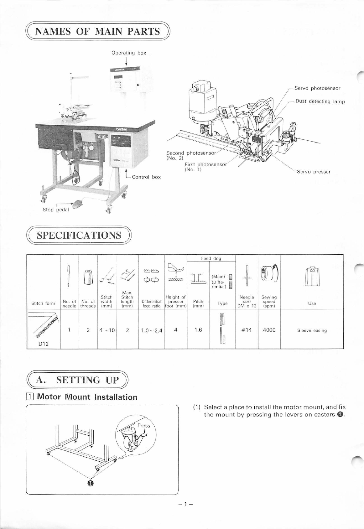
( NAMES
OF
MAIN PARTS )
Op
era
ting
~
•
' t
-
•
box
ll
Ser
vo photosensor
Dust
det
ecting
lamp
-··
l Cont rol
.....
fJ'
Stop
~
( SPECIFICATIONS )
/
/
10
~/
4
Max.
Stitc
length
(mm)
Stitch
f
orm
0
~
No.
of N
o.
of
threads
needle
1
2
_j__/
-./4._
Stitch
width
(mm)
4 -
7
012
h
2
box
~:!:!::>~
00
Differential
feed
ratio
1.0- 2.4
Second
(No. 2)
~
H
foot (mm)
First ph
(
eight
of
presser
4 1.6
photosenso
No.1)
l6
(mm)
Pitch
r
otosenso
Feed
r
dog
(Main)
(Oiffe· e
rential)
Type
~~
~8
[§
Ne
OM
I
~
+
edle
x 13
14
Sewing
speed
(spm)
400
SIZe
#
Se
J
0
Sleeve easing
rvo
presser
m
Use
OJ
SETTING
Motor
Mount
UP
)
Installation
0
(1) S
elect
a place
the
mount
-
1-
to
by
pressing
inst
all
the
the leve
motor
rs
moun
on
t, and fix
casters
0.
Page 4
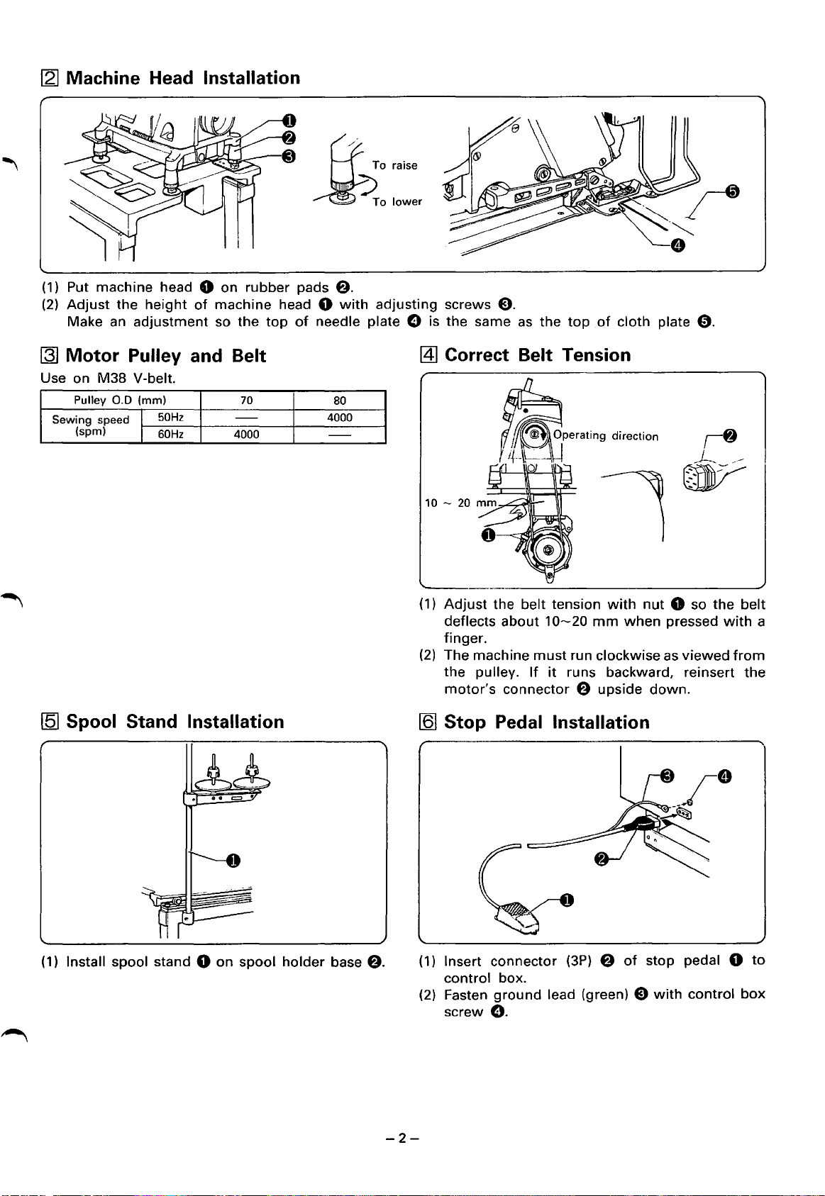
[2]
Machine Head Installation
(1)
Put machine head 0 on
(2)
Adjust
Make an
~
Motor
Use on
Sewing
the
Pulley and Belt
M38
Pulley
0.0
speed I
(spm) 1
height
adjustment
V-belt.
(mm)
of
50Hz
60Hz
machine head 0
so
the
-
4000
rubber
top
70
pads
8.
with
adjusting
of
needle plate 0 is
80
4000
-
screws
the
[4]
Correct Belt Tens ion
0.
same
as
the
top
of
cloth plate
0.
~
Spool Stand Installation
(1)
Install spool stand 0
on
spool
holder
base
f).
(1)
Adjust
deflects
finger.
(2)
The machine
the
motor's
[Q]
Stop Pedal Installation
(1) Insert connector
control box.
(2) Fasten
screw
the belt tension
about
pulley. If
ground
10~20
must
run clockwise as
it
runs backward, reinsert
connector 8 upside
(3P)
lead (green) 0
0.
mm
with
8
nut
0 so
when
of
pressed
viewed
down.
stop pedal 0
with
control
the
with
belt
a
from
the
to
box
-2-
Page 5
(B.
OILING
AND
OIL
DRAINING)
[I] Oil
The Brother oil included
lZI
to
be
Used
with
Oiling and Oil Changes
the machine should be used.
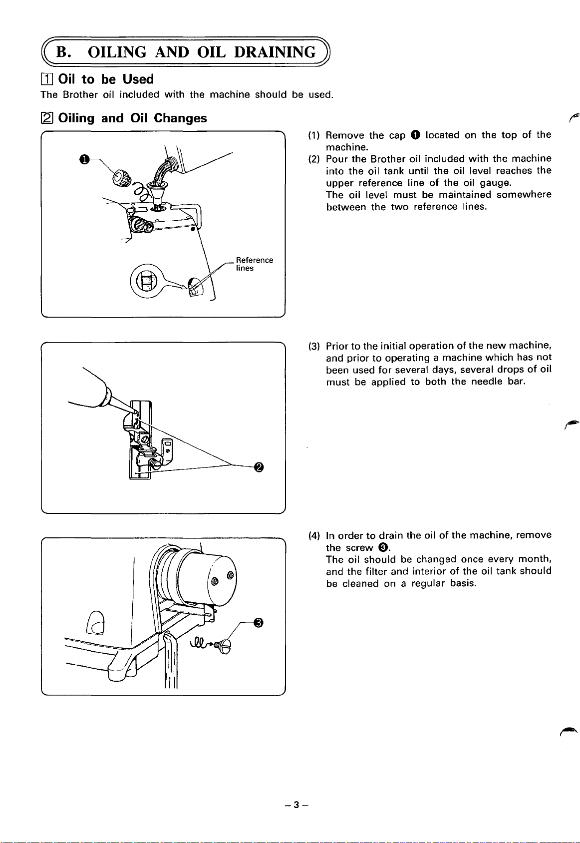
(1)
Remove the cap 0 located on the
machine.
(2)
Pour the Brother oil included
into the
upper reference line
The oil level
between the
Reference
lines
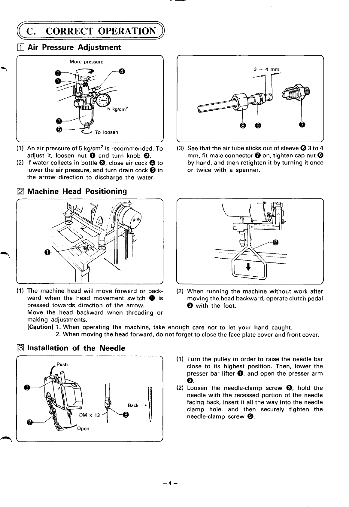
(3)
Prior to the initial operation
and
been used
must
top
with
the machine
oil tank until the oil level reaches the
of
the oil gauge.
must
be maintained somewhere
two
reference lines.
of
the
new
prior
to
operating a machine
for
several days, several drops
be applied to both the needle bar.
which
of
the
machine,
has
not
of
oil
-3-
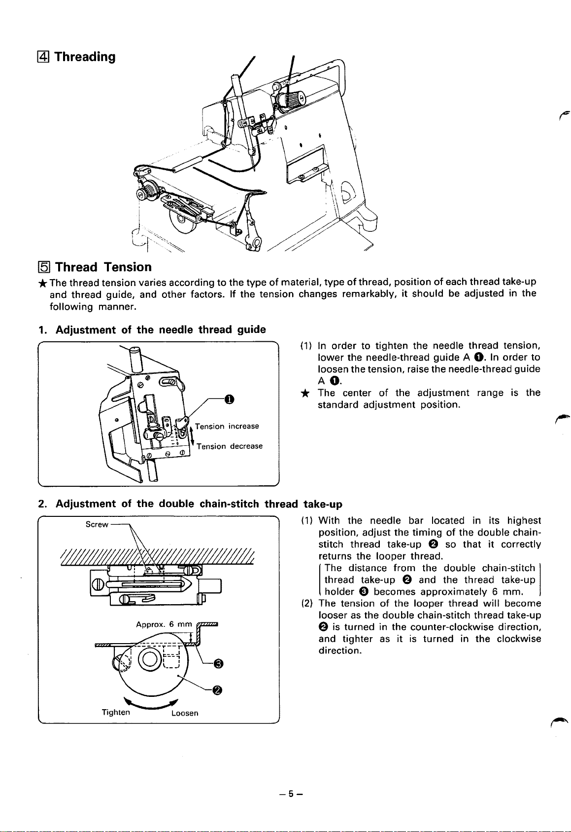
(4)
In order
the screw
The oil should
and the
be
cleaned on a regular basis.
to
drain the oil
0.
be
filter
and interior
of
the machine, remove
changed once every month,
of
the oil tank should
Page 6
~C.
OJ
Air Pressure Adjustment
CORRECT
More
pressure
OPERATION)
3-4
mm
~To
(1)
An
air
pressure
adjust it,
(2)
If
water
collects in bottle E), close
lower
the
arrow
the
[2]
Machine Head Positioning
(1)
The machine head
ward
when
pressed
Move
making adjustments.
(C~ution)
towards
the head backward
of
5 kg/cm2 is recommended. To
loosen
air
direction
1.
2.
nut
0 and
pressure, and
to
will
the
head
direction
When operating
When
moving
discharge the water.
move
movement
loosen
turn
knob
air
turn
drain cock 0 in
forward
switch
of
the
arrow.
when
the
threading
the
machine, take
head
e.
cock 0
or
back-
0 is
forward,
to
or
do
(3)
(2) When
enough
not
forget
See
that
mm,
fit
by
hand, and
or
twice
moving
e
with
care
to
close
the
air
tube
sticks
out
of
sleeve 0 3
male
connector
then
with
a spanner.
running
the head backward, operate clutch pedal
the
not
the
foot.
to
let
the
face plate
0 on,
retighten
machine
your
hand caught.
cover
tighten
it
by
turning
without
and
cap
work
front
nut
it
once
after
cover.
to
4
0
[3]
Installation of the Needle
CJBack-~
-4-
(1) Turn
the
pulley
close
to
its
presser bar
in
highest
lifter
0,
order
to
raise
position. Then,
and
open
e.
(2)
Loosen the needle-clamp screw E),
needle
facing back, insert
clamp
needle-clamp
with
the
recessed
it
hole, and then securely
screw
all
E).
portion
the
way
the
the
into
needle
lower
presser
hold
of
the
the
tighten
bar
the
arm
the
needle
needle
the
Page 7
~Threading
J~
1-
~···-.~~'
~r---.·;,
[5]
Thread Tension
*The
1.
thread tension varies according
and thread guide, and
following
manner.
other
to
factors.
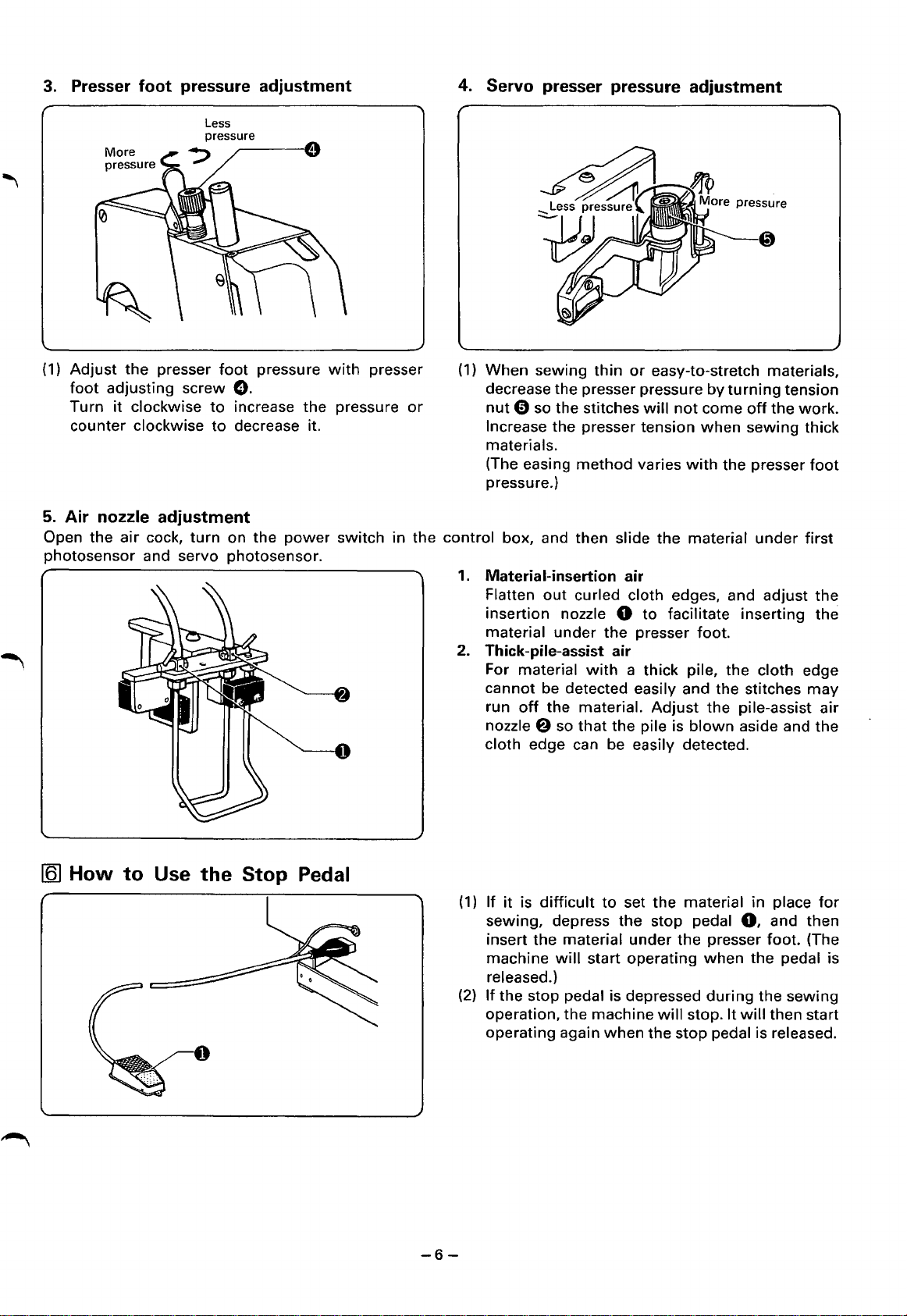
Adjustment of the needle thread guide
the
type
of
material,
If
the tension changes remarkably,
type
of
thread, position
(1)
In
order
to
lower
the needle-thread
loosen the tension, raise
AO.
* The center
standard
adjustment
of
each thread take-up
it
should be adjusted in the
tighten the needle thread tension,
guide
the
of
the adjustment range is the
position.
A
0.
In
order
needle-thread
to
guide
2. Adjustment of the double chain-stitch thread take-up
(1)
With
position, adjust the
stitch thread take-up
returns the
The distance
thread take-up
holder
(2)
The tension
looser
e is turned in the counter-clockwise direction,
and
direction.
-~
Tighten
Loosen
the needle bar located in its highest
timing
looper
thread.
from
8 and
e becomes
of
the
looper
as
the double chain-stitch thread take-up
tighter
as
it
is
of
the
double
e so
the double chain-stitch
approximately 6 mm.
turned
that
the
thread take-up
thread
in the clockwise
it
will
chain-
correctly
become
-5-
Page 8
3. Presser
(1)
Adjust
foot
Turn
counter clockwise
5.
Air
Open
the
photosensor
foot
the
adjusting screw
it
clockwise
nozzle
air
pressure
Less
presser
adjustment
foot
pressure
0.
to
increase
to
decrease it.
adjustment
cock,
turn
on
the
and servo photosensor.
the
power
with
presser
pressure
switch
in
4.
Servo
(1)
When sewing
decrease
or
the
nut
Increase
materials.
(The easing
pressure.)
control box, and then slide the material
1.
Material-insertion air
Flatten
insertion
material
presser pressure
thin
or
the
presser pressure
0 so the stitches
the
presser tension
method
out
curled cloth edges, and
nozzle 0
under
the
easy-to-stretch materials,
will
varies
to
facilitate
presser foot.
2. Thick-pile-assist air
For material
cannot be detected easily and
run
off
nozzle
cloth edge can be easily detected.
f)
with
a thick pile,
the material.
so
that
the
Adjust
pile is
adjustment
by
turning
not
come
when
with
the
inserting
the
the
the
pile-assist
blown
aside and
tension
off
the
work.
sewing
presser
under
cloth edge
stitches
thick
first
adjust
foot
the
the
may
air
the
[§]
How
to
Use
the
Stop
Pedal
-6-
(1)
If
it
is
difficult
sewing, depress
insert the material
machine
released.)
(2)
If
the stop pedal is depressed
operation,
operating again
will
to
start operating
the
machine
when
set
the
under
the
stop
will
the
material
pedal
the
when
stop. It
stop
in
0,
presser
the
during
will
pedal is released.
place
and
then
foot.
(The
pedal is
the
sewing
then start
for
Page 9
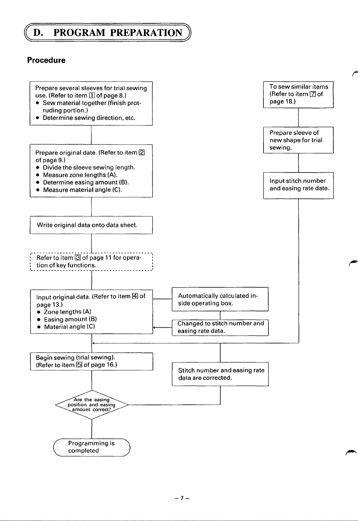
(D.
PROGRAM
Proc.edure
PREPARATION)
Prepare several sleeves
use. (Refer
•
Sew
ruding portion.)
• Determine sewing direction, etc.
Prepare
of
page 9.)
• Divide the sleeve sewing length.
Measure zone lengths (A).
•
• Determine easing
• Measure material angle
to
item
material
original date. (Refer
together
I Write original data
----------------------------------------
Refer
to
tion
item~
of
key functions.
of
III
of
amount
onto
page
for
trial sewing
page 8.)
(finish prot-
to
item
(B).
(C).
data sheet.
11
for
opera-
[21
To sew
(Refer
page 18.)
Prepare
new
sewing.
Input
and easing rate date.
similar
to
item
sleeve
shape
stitch
items
111
of
of
for
trial
number
Input
original data. (Refer
page 13.)
• Zone lengths (A)
• Easing
• Material angle
Begin sewing (trial sewing).
(Refer
amount
to
item
[Q]
Are
position
amount
Programming
completed
(B)
(C)
of
page 16.)
the
and easing
to
easing
correct?
is
item~
of
Automatically
side operating box.
Changed
easing rate data.
Stitch
number
data are corrected.
calculated in-
to
stitch
and easing rate
number
and
-7-
Page 10

[I]
Prior
to
Program Preparation
© Prepare 2 - 3 sleeves
1.
This machine can tack
side together.
for
trial sewing.
while
the material is laid
out
flat. Sew either the upper sleeve side
or
lower
sleeve
Upper sleeve
side
2.
As
for
the sewing direction, select the side which is least likely
amount
3.
When the joined edges are
to
as
the side
temporarily
secure the side
for
sewing to end.
Sewing
direction
to
be
tacked
from
sleeve
Lower
side
to
disturb the easing position and easing
or
pressed in order to keep them flat, use a heat-sealing adhesive
which
sewing
will
begin.
4.
Cut
off
protruding material whenever possible. If
material, which
5.
Make the left and right sleeves
will
make insertion, under the servo roller and presser
between the left and right sleeves
For materials such
programs
for
as
suede, etc., where one surface is raised and
the left and
Temporary stitch
by
sewing on the back and
can
be
right
sleeves.
Heat-sealing
adhesive
it
is folded
over
and tacked, a thick step
front
of
the material, respectively. Variations
foot
difficult.
decreased by making the sewing direction
difficult
to sew, prepare separate
will
uniform
result in the
in this way.
-8-
Page 11

121
Original Data Preparation
1.
Prepare a standard size pattern paper.
2. Draw
3.
finishing
Measure the intervals between points, and calculate the easing amount.
stitch lines
for
the
sleeves and body.
4. Divide the sleeve sewing length,
to
F).
(1)
By using points in this
simplified.
(2)
Consider each
(3)
Also, consider
changes in angle
5.
Measure each zone length (A).
portion
portions
way
which
which
as
one zone.
as zone markers, the calculation
including
has
the
have
only
an
allowance
same easing
small
Zone Order
for
stitching,
amoutn
6.
Determine
into a maximum
of
the easing position and easing
as
one zone.
the
easing
of
amount
16 zones (from 0
(8)
amount
for
each zone.
is
7.
Measure
finishing
zone. Measure these
vals.
the
material angle
stitch line and grain line
material angles in
(C)
between the
from
each
5o
inter-
-9-
Finishing
stitch line
~45°
Grain line
Page 12

8.
Write the original data
Zone No.
Zon_e
Easmg
length
amount
Finishing
stitch
1
line
4
0
onto
Material
angle
the data sheet.
Point
@]I
33
4
[§]
38
4
Grain line
Original Data
Zone
No.
0 14
1 48
2
3 14
4 34
Zone
Length
A (mm) B (mm)
Easing
Amount
0 45
4
40 4
0 90
5
5 33 4
6 38 4 25
7 86 2
8
9
A
8 72
65
65
0 65
2 85
67 4 40
5
Material
Angle
c (
0)
50
65
65
40
20
40
Data Sheet
Calculated Data
Stitch
Number
Easing
Rate
Modified
Stitch Easing
Number
Data
Rate
Remark
c
D
E
F
TOTAL
8 0
40
~
~
-10-
~
Page 13

[3]
Key Functions and
1.
Material
Key: Used
Methods
to
adjust
for
of
the
Use
difficulty
of
easing
for
each
type
of
material.
Considering the
-
[Q].
2.
Pattern Key: Used
Size key: Used
© Relationship
(1)
When patterns
standard pattern size. Centering on
increased
calculated.
~
0 I 2 3 4 5 6
of
or
decreased 2%
(The sewing pitch is fixed at 2
to
adjust
to
adjust
the
Pattern Key and Size Key
from
0 - 9 are selected and
0
I v
number~
0
Materials easily
eased
for
the
design
for
the size
this
for
each succeeding
~~
8 9 A B C D E F
v
key
to
be
2@.1456
Stan-
dard
oE-
of
the sleeve.
of
the
sleeve.
programmed,
standard size
mm.)
the
standard degree
Materials eased
--,)
size 7 is automatically memorized
7,
the stitch
number
or
of
easing, select a key
with
difficulty
number
letter and each size is automatically
for
the
sewing length is
* The
program
(designated
gram)
automatically memorized.
The data
than size 7
cannot
of
each pattern is
for
yet
from
as
for
size 7
~
in
the
sizes
other
[0-6,
be changed.
8-F]
[Q]
the
dia-
5
6 Stitch
~--+-finished
1---7-+-
is decreased 2% per
8 numbfer.
I I
number
sewing length
1 1
1
of
9
Example: The
following
is the result
em.
em x
50
Size----Finished
~~~~;:spending
armhole
_2_
100 1 em
sewing
- 43··.· .. ·48
length)
i/
1/
" I I I I
~
~v·u;
-~
~
"C
~
00
I
of a program
em (Length is increased
=
1
o
......
Stitch
~~finished
-;-
is
number
I I I I I I
1
for
s 6
49
.
number
sewing length
increased 2% per
or
letter.
in
which
the
finished sewing length (armhole length) is
or
s g
51
decreased
or
letter.)
......
52···· ..
each
[1]
50
number
--
of
-f--
-f--
50
F
58
-11-
Page 14

(2}
When patterns
(ten sizes
automatically done.}
from
from
0 -
A-
D are
to
be selected and
9}.
(Totalling 40 kinds
programmed,
of
programs
they
must
are possible
be
programmed
to
be memorized
for
while
each size
it
is
not
3.
Zone
Key:
lzonej
4.
Number/Letter
[Q]rv[EJ
5.
Data Mode
loataj
6.
Diagnosis
Used
Key:
Key:
* Programs can be memorized in each
portions
to
store and display data (stitch number, easing rate}
Keys:
Used
malfunctioning
Used
Marked
to
for
with
input,
self diagnosis
the
numbers
modify,
location. (Refer
or
display original data, stitch number, and easing rate.
in
the
0 - 9 and letters A -
event
of
a circuit malfunction, and
to
page 19.)
designated~.
for
16 zones.
F.
for
a check
of
of
the
the
7.
Input 1
8.
Run
9.
Input 2
10. Causes for the warning sound:
Key:
Key:
r:=1
~
Key:
(lnp21
Used
for
8, etc.)
Used
to
data
portion
Note: If
(A
Used
each item
to
input
original data (A, 8,
change
the
warning
to
from
of
the
display.)
stitch
number
sound
memorize corrected
of
input
C).
Press once
the data
data.
1.
2.
3.
4.
mode
to
the
data
for
zone 0 is
will
be produced.)
or
input
data
Incorrect key operation.
Input
value is outside prescribed range.
Malfunction
Completion
(Ideally, the
almost
found
of
completion
simultaneous.)
for
each
sewing mode. (
"00",
the
unit
for
stitch
number
in diagnostic mode.
program
during
of
sewing and
item
of
input
data (once
GO
will
sewing.
"GO"
is indicated in the
not
enter
the
sewing mode.
and easing rate. Press once
the
warning
for
A, once
for
sound are
-12-
Page 15

~
Inputting Original Data
© The Number/Letter Keys are displayed
as
shown
below.
Key
Display
Material Pattern Size Zone (Stitch) (Easing rate)
©
Input
the
1. When a
,-
J
6
,-
0
0
,,
Ll
I
2
, ,
I
I
c
3 4 5
LJ
J
\IIIII[IJ[IJ\
Data
7
Data
Dia
lnp1
Run
lnp2
Mat
c
8
4 5 6
0
original data
pattern
from
Pat
Size Zone
D E F
9 A B
1 2 3
from
the data sheet. (For
0 - 9 is selected:
7 8 9
,,
,,
,
I
D
J
Power
@]
information
8
l
0
c
D E
,-
L 0
Zone
No.
0
1 48 4
2
the
,-
I
c
Data Sheet
Zone
Length Amount Angle
A (mm) 8 (mm)
14
40 4 65
.......--
data sheet, refer
Original
A
,,
,-,
concerning
* Portions flashing on and
F
,-
,-
Data
Material
Easing
c (
.,
45
0
50
--..._
to
page 1
off
can be changed.
\
0.)
Procedures
<D
Turn on the
operating box. power switch was
power
switch
of
the
Key
Operation Display
The
same
information that
IYI~I=tlt
®Press
the
@Press the Data Key.
@Press the Zone Key, and then the
Number
*The
the Pattern Key,
Number
above step is
if
"0"
in the zone position.
Key
"0".
Key
"0".
not
is
already being displayed
and then
necessary
EJ
t
[Q]
(oataJ
jzoneJ
t
IYIYiul
1
Ylal
l3lttl11'''•
"Sta~ard"
displayed
I
-Ill
last turned off will
).
Flashe
on
Yiul
{umbers
till
)
was
''
rn
rn
and
off
rn
t
Flashe
on
rn
Flashe
on
displayed before the
be
displayed.
1u1u1
It
dttl
It
dt
11
rn
Data
is
displayed.
and
off
rn
and
off
[Q]
®Press
the
Input
1 Key.
(
lnp1J
-13-
l=lltllllal
'~''tllluliRI
rn
rn
1
rn
Flashe
on
t
and
off
Page 16

Procedures
@Input
the sewing length 1114
in the data A position, and then
press the Input 1 Key.
mm"
Key
Operation
Display
I.__
l....__.ul....__l_u
I
rmJ
[mJ
https://manualmachine.com/
14mm~~
easing
11
0"
(f)
Input
the easing
data 8 position, and then press the
Input
1 Key.
amount
;1
K[>;ot
®Input
the data C position.
the material angle 1145"
in the
in
@]
!
Flashe on and
11o11u1mrn
L--.....1...-____._____ Flashe on and
1
lL-...1..-1
L-.~-
1
I
IOI
l-_.....L.:..:----1...-.--
I
IOI
1
___._I
L_
1 m I a I a I
lui
[ill
lull!
I
rn
Flashe on and
off
11'1151
off
off
~
j Grain line
®Repeat
zones 1 --C.
@)When data
zone D stitch
automatically displayed.
@Press
steps ®
input
is
number
the Start Key.
through ® for
compl~~ed:,
00
t~e
IS
I
lol
The next zone (1)
1
1o1
Indicates that the program has been completed.
I3IOI7Ial
Ill [ffi]
1s
automatically displayed.
ldllalal
[0
rn
Flashe on and
rn
_,
IGial
off
-14-
Page 17

2.
When a pattern
from
A - D is selected:
Procedures
CD
Turn on the
operating box.
® Press
the
@Press the Size Key, and then the
Number
the
Letter Key
n
~
A
8
power
Pattern Key,
"A".
"0".
Key
I
0
~~
\
\
Program here
switch
2
of
the
and then
Key
B
~
[K]
I Size I
~
[QJ
Operation
The
same
information that
power switch
I
I
[I
I
IRI
I
IR[I
I
IHIOI
I
Display
was
last turned off will
I
I
I
LFiashe
on and
I
LFiashe
was
displayed before the
be
displayed.
IDJDJ
IDJDJ
off
IDJDJ
IDJDJ
on and
off
IDJDJ
@)
Press the Data Key.
®For
®Press
0
1.
2.
0
1.
the
following
items
procedure on page
If
If
If
llnp11
If
Press I Zone
@ - @
the Run Key.
a mistake is made
data has been
data has been
, and then
a mistake is discovered after all
steps, refer
of
input
input
input
I--')
I
Number/Letter
the
"0 -9"
13.
while
up
to
up
once again
to
inputting
data A
to
data
or
Key
loatal
EJ
data:
data
B,
press l Data
C,
press lzonel--') !Previous Zone Number/Letter Kevl--') !Datal--')
from
data A.
the
data has been
of
mistaken
I
~
I3IHIUI
t
Standard numbers
displayed
Input
data A,
B,
I3IRIOIOI
I--')
~and
input:
I Data
I--')
then
j1np1l
IBDJ
Flashe on and
c.
OJ
input
once again
.
t Data is displayed
off
IGIOI
from
data
A.
(Note)
1.
If
the
machine is
prevent this,
2.
Input
data
may
the
machine.
not
used
the
power
be affected
for
a long period
to
the machine
by
lightning.
of
should
If
lightning
time
-15-
(one
month
be
turned
occurs in the vicinity, disconnect
on
or
for
more), the
1 - 2
input
hours
data
every
the
may
month.
power
be lost. To
plug
of
~
Page 18

[Q]
How
,
J
to
,,
Ll
Sew
,
,,
I
u
rn
,-
,,
Ll Ll
(1)
Open air cock
pressure is 5 kg/cm
(2)
Push the
(3)
Push control box
(4)
Push operating box
(5)
Confirm that the material, pattern, and size are
correct.
(6)
Put the machine into the sewing mode.
0,
motor's
and make sure
2
•
power
power
switch 8 ON.
switch
power
switch 0 ON.
6)
that
ON.
the air
0 Chain Length Adjustment
POWER
CHAIN LENGTH
@
shorter
stitch " stitch
ON
~a
(][]m
Longer
OFF
(7)
Insert the
and servo presser. The machine
sew.
Confirm that the
simultaneously
indicate
pleted.
(8)
The thread cutter
final chain stitch.
(9)
The machine
(about one second later) and enter the sewing
mode again.
(1)
After sewing the work, adjust the chain lengths
off
Knob is used
operating
The larger the
chain length.
the
work
smoothly
warning
with
that
the program has been com-
will
will
work
at the beginning and end.
for
timing.
number
under
sound is produced
the end
then operate
return
to
adjusting the chain cutter
the longer
the presser
will
of
sewing
to
the
first
will
foot
begin
program
to
to
cut the
be the
-16-
Page 19

[Q]
Program Modification (Easing Position and Amount)
1.
Write
the stitch
Data
Input Operation
number
and easing rate data calculated inside the operating box
B
l
8
1
[Q)
1
OJ
1
[[)
lnll''l'll''lnl
~u
'uu
JJJI2121m
J2]
[JIBJ
lOlBI
onto
the data sheet.
~
[9
l
[QJ
!
[ID
l
~
Zone No.
0
1 48 4
2
Zone Easing Material
length
A (mm)
14
40
14
~~~
c
--
c::r
2
Jr]
-od
_jQJ
IOIYIIOIOI
lunlunllu''lu''l
- the final zone.
IEII3ISIIOIYI
)
IFIIJI5IIOISI
Data Sheet
Original Data Calculated Data
Amount
B (mm)
0 45
4
0
~
0 40 04
Angle
c (
0)
50
65
~~
Stitch
Number
07
22
18
Easing Stitch Easing
Rate
00
06
08
~
00
11
The
00" stitch
If
data is
ignored.
Modified
Number
~
input
number
after the
Data
Rate
-:::::::::--
here indicates
"00"
indication,
Remark
~
that
cis
it
is
~
D
E
F
TOTAL
2.
Modifying
(1)
If
the easing
~
<
the Easing Position and
00
---1
~
.-....
amount
[§] (Select when easing
is entirely
0 J (Select when easing
~
too
00
Amount
small
amount
amount
~
or
too
-17-
00
great,
is
too
is
too
modify
great.)
small.)
-------
the material data.
Page 20

(2)
If
*
Example:
If
(3)
stitch
the
The
rate
The
the
easing
easing
number
maximum
easing
number
amount
amount
is increased.
easing rate
Changing
from
10
position
data.
to
is
will
the
13.
is
partially
increase as
number
easing rate
not
correct,
Zone 4 stitch
18 stitch
too
the
modify
small
in
or
easing
is 28.
zone 4
the
number : 15 -18
too
great,
correct
the
easing rate.
rr
Zone
No.
4
5
6
Changes
Data Sheet
Calculated Data
Stitch
Number
Easing Stitch
Rate
10 18
15
15
08
17
08
to
the next zone
Modified Data
Easing
Number
Rate
12
17
13
08
08
B-B-~-B-COOO-B-CO~-B-CO[ID-8
(Stitch number) 1 (Easing rate) J (Stitch number)
If this data is
2 Key.
* The display changes successively each
the Input 2 Key is pressed.
not
to
be
changed, press the
Input
time
111
Preparing Data for Similar Items
© If a
1.
2.
program
prepared,
Select
Write
the
Example: Display
for
sample-sewn
program
is
it
can be easily
the
program
data
to
of
be
the
made
that
new
for a pattern
done
is closest
program
by
to
l
I
Data
I
1
EJ~
1
8[ID
1
which
using
the
new
into
is
the
pattern
the
only
slightly
program
data
Because
the
Return
for
in
material,
calculation
the
material and size
to
original
different
the
machine
from
previous
size, etc., and use
column
has been
become
program
one
which
pattern as a base.
of
the
put
standard.
has
it
to
data sheet.
into
already
sew
the
been
a sample. , /
data
mode,
-18-
Page 21

IYI!I9IDI
1....-------r-
y
l---.--119......,........1
OJ
Write
data contents onto data sheet
II
OJ
OJ
OJ
Number
3.
Modify
the data sheet. (Refer
4.
Input
the
changes.
key
last zone
the stitch
new
program
of
number
and easing rate data
to
page 18.)
into
an
unused pattern,
as
required, and
or
input
it
into
a previously used pattern and
EJ-D-8-@J-B-DD-8-DD-8-
turn
of
Input
rate data
on the
the
control
during
(Number key
from
0 -
9)
[B]
Self Diagnosis
© Investigates the problem area
control circuitry.
1.
Move
2.
Turn
operating
power
3.
Close
box.
the machine head backward
off
the
switch again.
the
Display
power
lever 0
air cock, and then
during
switch
from
correct
of
the
turn
operation
loataJ
~
Input stitch
data
if
something abnormal occurs in the
from
the table.
the operating box, disconnect the
power
switch, and then
off
the
power
switch
Display
write
this
in the
easing
abnormality
modified
Input
final zone -
data
up to
Malfunction location
column
write
in
1()1
~
(Stitch data
of
next zone)
of
the
\
8
!
lr-[ ,...------,1
h
1.-------.E
,____,[
I
OJ
(CHECK)
IPIRislsl
(PASS) ! (RAM)
!
OJ
IPIRISISIOJI,
(PASS) i (ROM)
The operating lever moves and the
turns
on. i
ISIYiniCI
(SYNCHRONIZER) !
OJ
IOili213IIYISIIhl!l
(0
- 7 is successively displayed, one
time
each
1.-----.P
I Display returns
the pulley is rotated.)
i
1.-------.R
,----5,--S
(PASS) i (ALL)
II
to
original condition I
It
rn
power
OJ
digit
I R II!
IR
I
lUI
switch
at a time,
,,
I
I
IEI,Jr-IOJrn
I
IEir
1.
The pulse
2.
The pulse
IIIIIOJOJ
(ERROR)
(ERROR)
motor
motor
Warning sound is produced.
Jr
I
OJ
Warning sound is produced.
does
will
not
(No display)
I'
not
operate.
stop operating.
!Ill
Memory
and circuit board
Memory
and circuit board
1.
2.
Synchronizer and
cord
(RAM-TC5516)
(ROM-2532)
Origin switch, cord
and connector
Origin switch
I
-19-
Page 22

OPERATION FLOW
CHART)
Open the
Motor
Control
ON
Operating
switch
Insert the material
the No.1 photosensor
Insert the material
the servo photosensor
air
power
box
box
ON
cock
switch ON
power
switch
power
under
under
The servo presser rises
clutch
motor
The
power
The
control
The
play
illuminates
The material-insertion air
is
The servo presser and
presser
The servo roller rotates
The machine operates
box
power
ofthe
emitted
foot
rotates
lamp
of
illuminates
lamp
operating
the
and dis-
lowers
box
Confirm
pressure is 5 kg/cm
The presser
Confirm
is in the sewing
(Press
The material insertion
stops
The synchronizer begins
stitch
that
foot
that
the
Run Key.)
number
the air
2
rises
the
machine
mode
detection
air
Insert the material
the No.2 photosensor
material moves away
The
from
the No.1 photosen-
sor
The material moves away
from
the servo photosen-
sor
material moves away
The
from
the No.2 photosen-
sor
under
program
The
*
If
a long period
moves
operates and the material insertion air is emitted.
The servo presser rises
The machine stops
The sewing
completion
sounds at the same
that
the
The
time
before the chain cutter operates varies according
The chain
begins
of
below
program
cutter
time
the No.2 photosensor,
program
signal
time
finishes
operates
passes before
* The sewing
The
ted
the
the
The servo roller stops
The synchronizer finishes
stitch
should ideally
with
the end
of
pile-assist
material
chain
number
the
chain stitch length control.
air
cutter
detection
program
sound
of
sewing.
is
emit-
compeltion
simultaneously
to
the
adjustment
signal
The presser
-20-
foot
rises
The material insertion
is
emitted
air
Page 23

TANDARD ADJUSTMENTS
Adjustment of the Needle Bar
9
mm
(1)
Adjust
when
Adjust
center
[21
Adjustment of the Double Chain-stitch Looper
the distance between
the needle is located at its highest position.
by
rotating the needle bar around the
of
the hole in the needle plate.
the
tip
of
the
needle and the
double
top
surface
chain-stitch needle is located directly above
of
the needle plate
should
be 9
mm
the
1
1
(1)
Install the double chain-stitch
it
all
the
way
into
the
double
holder.
of
The angle
contact
inclination is determined by the
point
on the shaft.
~0-
(3)
Set the machine so
chain-stitch
chain-stitch needle
and then make the necessary
the
clearance between
chain-stitch
needle is
If
the
the
tip
contacts the double chain-stitch needle and
pushes
looper
looper
0 - 0.05
machine skips stitches, adjust
of
the double chain-stitch
it
0.05 -
that
is aligned
as
the needle travels
and
mm.
0.1
looper
chain-stitch
0.05
mm
the
tip
of
with
adjustment
the
tip
of
the
double chain-stitch
mm.
by
inserting
looper
the double
the double
upward,
so
that
the
double
it
so
that
looper
(2)
Adjust
chain-stitch
there is 2
chain-stitch
chain-stitch needle.
(4)
With
in item (3), push the
with
0,
between
tip
Also provide a clearance
between the double chain-stitch needle and the
front
as
necessary so that,
looper
mm
looper
the machine set in the
the back
and
provide
the
of
the
double
double
is at its farthest left position,
between the
and the center
double
double
double
chain-stitch needle guard
chain-stitch needle guard
a clearance
chain-stitch needle and the
chain-stitch looper.
when
tip
condition
chain-stitch needle
of
the
of
the double
of
the
of
0 - 0.05
0.3 - 0.5
described
double
double
mm
mm
~
e.
-21-
Page 24

[31
Adjustment of the Feed Dogs
~
Stitch Width Adjustment
© Close
the
air cock before making
1.3
this
adjustment.
mm
(1)
Turn
the
pulley
uppermost
Then, adjust the
0
to
above the upper surface
then secure.
(2)
Adjust
the teeth are at the same
the differential feed dog
position.
be 1.3
the height
mm
Needle center
front
to
raise
the
feed dog
of
the differential feed
(for
medium-thick
of
the
needle plate, and
of
the main feed dog 8 so
height
as
the
0.
to
its
dog
materials)
that
teeth
of
(
1)
Loosen the screw
(2)
Loosen the screw @, move the
(3)
Position the presser
(4)
Insert the material
position
photosensor
lower
If the servo photosensor 0 is positioned closer
sewn
may become
(5)
If
the
where
knife.
curled
dust
detection
0.
foot
F 0 so
under
it
stops. Then, loosen
the
0 back and forth
or
with
an increase in
loose
or
even come
lamp
0 illuminates, clean
lower
that
it
first
0 and servo photosensors
until
the
the
off
knife 8
lightly
edge
cutting margin.
the
to
a suitable position, and then tighten the screw @.
contacts the
Side A
the
adjusting screws 0 and adjust
of
the
material is approximately 0.5
to
the
work.
the
Stitch
4-10
mm
•
lower
knife
8,
and then tighten the screw
Reflecting tape
0,
and
put
the servo roller 0
by
moving
mm
from
pulley side than mentioned above, the
If
it
is positioned closer
glass above the reflecting tape
to
the front, the stitches
with
width
into
the servo
side A
work
a cloth.
of
will
0.
the
the
be
-22-
Page 25

[5]
Adjustment of Cloth Detector
··~
·•
:~,,-~
.·~.
·~·
(1)
The cloth detector detects
second
The
(a)
(b) Then
(c)
[Q)
Installation of the Knife
photo
first
and second
Turn the
goes out.
turn
In case
emitting
from
of
the
extinguish~m4
@ 1 9
sensor ~ (for the cutter). (The cloth detector is located on the side
screw
the
thick materials,
diode
has lit. In case
position
~
2 8
0
whether
photo
counterclockwise
screw clockwise
where
sensors can be adjusted in
turn
the
Turn
from
full position
~lighted
one-half
from
position
111
s a
lights
7
10
there is a cloth
with a screwdriver
until
the
the
screw clockwise 2 degrees
of
very
thin materials,
light
emitting
light
diode
under
emitting
(1)
to
one
the
•----~n-
·-~~,....,.-
the
first
photo
the
same
until
the
diode
further
turn
the
screw clockwise
has lit.
When the knives have been replaced,
lower
imately
knife 0
light
0.01
sensor 0
way
emitting
lights.
from
to
mm
(for
machine start) and
of
the control box.)
as
follows:
diode
(LED)
the
position
about
make a clearance
with
the
where
1 degree
upper
on
the
right
the
light
further
adjust
of
knife shaft.
the
approx-
(2)
Adjust
* Make sure
rack e and
Approx. 1
rack 8
with
that
pinion
mm
nuts
upper
Q so
knife 8 has a vertical
0 freely
upper
move
knife 8 engages
in
play
proper
-23-
lower
of
less than
engagement.
knife 0
approximately
by
approximately 1 mm.
0.3
mm
at
the
tip
and
that
Page 26

(TROUBLESHOOTING
GUIDE)
~-----T_r_o_u_b_le------~~~
~-------c_a_u_se
Wrong
______
threading.
~
~-----•n_s_p_e_c_ti_o_n
Threading.
~
Excessive tension disc
pressure.
H
1-
Poor-quality thread.
t--
Tension disc pressure.
Thread quality.
____
~ll
f---
~------R--em
See paragraph on threadin g.
Adjust
ure.
Use thread
ty.
__
e_d_v
to
proper press-
of
good
______
quali-
~IP_a_g_e~~
5
lLJ
L
Thread break
I
Thread is
r--
needle eyelet.
Needle
~
rectly.
Needle groove and needie eyelet finished poorly.
H
Needle, loopers and
thread takeups
-
tioned properly
another.
too
thick
for
installed incor-
not
posi-
to
one
-
1---
t---
Needle size.
Direction and height
needle.
Needle groove and needie eyelet.
Clearance between needie and looper; position
of
thread takeups.
of
Use needle
f---
of
thread
count.
See
1---
installing.
Replace
1---
die.
See
adjustment
-
double chain-stitch looper and thread tension.
of
correct size
of
correct
paragraph on needle
with
good
nee-
paragraphs on
of
needle bar,
4
4
4
21
5
Stitches
skip
Needle, loopers, needle
plate, thread passage
---
have flaws.
r---
Wrong
threading.
Excessive tension disc
pressure. ure.
H
Needle installed incorrectly.
i
Needle
point
blunt
not
to
or
have incor-
r--
'--
bent.
Needle, loopers and
thread takeups
tioned properly
1-
another,
rect clearance.
Needle and needle
not
1-
positioned properly
to
one another.
or
posi-
one
guard
-
1---
H
H Needle
r--
1--
Flaws
of
ers, needle plate, thread
passage.
Threading.
Tension disc pressure.
Direction and height
needle.
Clearance between needie and loopers. Timing. Thread takeup
position.
Clearance between needie and needle guard.
needle, loop-
point
and bend.
of
Smooth
-
buff.
See paragraph on thread-
1---
ing.
Adjust
to
See
paragraph on needle
installing.
H
Replace
y
See
paragraphs on
adjustment
1---
1---
double
and
looper.
See
paragraphs on
adjustment
chain-stitch looper.
will
oil stone
proper press-
with
new needle.
of
needle bar
chain-stitch
of
double
or
I
5
v
4
4
21
5
21
Looper
point
down.
~
hangs
-24-
Looper point.
Correct
replace
with
oil stone,
with
new looper.
or
~
Page 27

L_
____
~------T-ro_u_b_l_e
______
~ll
L
________
c_a_u_s_e
______
~
l_n_s_p_e_~_i_o_n
____
_JI
LI
_______
R_e_m_e_d_v
______
~IP_a_g_e~~
Needle break
Doesn't
!cloth.
(Double-chain
work
well
stitch
without
sewing)
Needle installed incor-
,....-
rectly.
~
Needle bent.
1-
Needle and loopers positioned
1-
L-
.....--
f-
~
1--
improperly
another.
Needle and needle guard
positioned
one another.
Wrong
threading.
Tension
looper threads are
great
Needle thread
positioned incorrectly.
of
or
too small.
to
improperly
needle and
too
guide
one
to
1---
1---
-------
-------
-------
1---
1---
Direction and height
needle.
Needle bend.
Clearance between needie and loopers,
timing.
Clearance between needie and needle guard.
Threading.
Tension disc pressure.
Thread
guide
of
their
position.
See paragraph on needle
1---
installing.
Replace
with
t-
See paragraphs on
adjustment
1---
and double chain-stitch
looper.
See paragraphs on
adjustment
1---
and double chain-stitch
looper.
See paragraph on thread-
....___
in g.
Adjust
1----
~
to
sions.
See paragraph on adjustment
of
stitch needle thread
guide.
double-chain
new
needle.
of
needle bar
of
needle bar
correct ten-
4
4
21
21
5
v
5
When
the
power
turned
on,
in
the
Material, Pattern,
Size, and Zone displays.
No
response
pressed.
"0"
is indicated
when
switch
keys are
is
Wrong
I-
'---
,.......
1--
L..-
1--
L-
timing
chain stitch thread takeup
assembly.
Main and differential feed
dogs are
one another.
The
turned
through
and the
indication is displayed.
The data back-up battery
is depleted.
A key has
its original position.
not
power
off
self-diagnosis,
"
of
level
has been
midway
Sl.fn(
not
returned
double-
with
(Sync.)"
I---
1---
f---.
to
-------
Thread takeup
Feed dog height.
Check data.
Return key.
timing.
See paragraph on adjustment
of
1---
stitch thread takeup and
thread guide.
1----
1---
1----
double-chain
See paragraph on feed
adjustment.
Press the Data Key.
Replace the circuit board.
Turn on the
again. Press the Diagno-
for
sis Key
Fix on correct position.
power
switch
self-diagnosis.
5
22
19
v
19
v
-25-
Page 28

"\
Machine
Trouble
won't
start.
I
I
First photosensor's
too
is
Cause
strong.
light
I
I
Inspection
First photosensor's
light
intensity.
I I
Adjust
Remedy
cloth detector.
I
Pagel
Servo
motor
won't
The machine starts
as
the
power
is
turned
Servo
motor
only.
Machine
Cutter
Cutter
should
runs one
won't
won't
operate.
operates
not.
stop.
where
start.
as
soon
on.
way
it
Fuse is blown.
1--
Either the material plate
surface under the first
1--
photosensor is dusty
the sensor
weak.
1--
Fuse is blown.
First photosensor and
second photosensor's
-
light
are
too
First photosensor's
1--
is
too
weak.
Cutter operating
r-
wrong.
Second photosensor's
f-1.--
light
is
too
light
is
weak.
strong.
or
too
light
timing
1--
-
~
-
1--
is
1--
1--
Fuse.
Dust on the materialplate surface
strength
sensor light.
Fuse.
First photosensor and
second photosensor's
light
are intensity.
Second photosensor's
light
intensity.
Cutter
Second photosensor's
light
intensity.
of
first photo-
timing.
or
Replace the fuse in the
r--
circuit panel.
Clean the material-plate
surface.
-
detector.
Replace the fuse in the
1----
circuit panel.
Adjust cloth detector.
-
1---
Adjust cloth detector.
r--
Adjust control box screw.
Adjust
1---
Adjust
cloth detector.
the cloth
v
23
v
23
23
16
23
-26-
Page 29

~ADJUSTMENT
OF CIRCUIT
BOARD)
@ Close the air cock and push the control box power switch ON.
Feeding direction
STP
~
..,._
(Vide A) (Vide
+ H
~~~c.n
a;
~
e(9
< L e (5 V) "'0
~~
o
±0
V C2DC1DDDCP
B)
@@
CLOSE
V)
OPEN
~
DO
DOoo
(Vide
C)
1.
Right/Left Balance & Output Adjustment of Servo
board (right end in above figure) beforehand].
(1)
Put the edge
and set
(2)
Take measure
adjust in such a
(vide
C).
Also, when removing
2.
Adjustment of Dust Sensor
(1)
Take measure
tester.
(2)
Make adjustment by
between
of
material in
it
at the position
of
the voltage between
way
(0.4-1
±0
V terminal and
the
midst
where
that
it
will
be 5 V
the
material
V)
of
the voltage between
turning
volume
DD
of
light
LED
"PHM"
±0 V terminal
by
turning
out
(vide A),
DD so
terminal
of
that
(-).
Motor
photo
sensor (vide
just
illuminates
and ANP terminal by AC
volume
turning
±0 V terminal
the
"CLOSE"
amount
[Please remove the fuse
or
volume
and
of
voltage
B)
and
turn
the
servo balance
just
puts off.
50
V range
when
inserting the material
"OPEN" and adjust
CP
terminal
will
be
(+)
half
by
DC
of
it
above
on
circuit
"BAL"
of
tester and
forward
to
be 9
1 V range
amount
V.
of
r-".
-27-
Page 30

BROTHER
INDUSTRIES, L TO.
NAGOYA,
JAPAN
...
r
I
I
151-150
192150-0-02
8512
<D
Printed in Japan
 Loading...