

Page 1
Installation and Operation Manual
X-SE-0254-eng
Part Number: 541B129AAG
September, 2010
Gas and Liquid Mass Flow
Secondary Electronics
Model 0254
5
Model 0254
Table Top Four Channel
Secondary Electronics
Page 2

Installation and Operation Manual
X-SE-0254-eng
Part Number: 541B129AAG
Model 0254
September, 2010
Essential Instructions
Read before proceeding!
Brooks Instrument designs, manufactures and tests its products to meet many national and international standards. These products must be properly
installed, operated and maintained to ensure they continue to operate within their normal specifications. The following instructions must be adhered to
and integrated into your safety program when installing, operating and maintaining Brooks Instrument products.
• To ensure proper performance, use qualified personnel to install, operate, update, program and maintain the product.
• Read all instructions prior to installing, operating and servicing the product. If this instruction manual is not the correct manual, please see back cover
for local sales office contact information. Save this instruction manual for future reference.
WARNING: Do not operate this instrument in excess of the specifications listed in the Instruction and Operation Manual. Failure to heed
this warning can result in serious personal injury and / or damage to the equipment.
• If you do not understand any of the instructions, contact your Brooks Instrument representative for clarification.
• Follow all warnings, cautions and instructions marked on and supplied with the product.
• Install your equipment as specified in the installation instructions of the appropriate instruction manual and per applicable local and national codes.
Connect all products to the proper electrical and pressure sources.
• Operation: (1) Slowly initiate flow into the system. Open process valves slowly to avoid flow surges. (2) Check for leaks around the flow meter inlet
and outlet connections. If no leaks are present, bring the system up to the operating pressure.
• Please make sure that the process line pressure is removed prior to service. When replacement parts are required, ensure that qualified people use
replacement parts specified by Brooks Instrument. Unauthorized parts and procedures can affect the product's performance and place the safe
operation of your process at risk. Look-alike substitutions may result in fire, electrical hazards or improper operation.
• Ensure that all equipment doors are closed and protective covers are in place to prevent electrical shock and personal injury, except when
maintenance is being performed by qualified persons.
WARNING: For liquid flow devices, if the inlet and outlet valves adjacent to the devices are to be closed for any reason, the devices must
be completely drained. Failure to do so may result in thermal expansion of the liquid that can rupture the device and may cause personal
injury.
European Pressure Equipment Directive (PED)
All pressure equipment with an internal pressure greater than 0.5 bar (g) and a size larger than 25mm or 1" (inch) falls under the Pressure Equipment Directive
(PED).
• The Specifications Section of this manual contains instructions related to the PED directive.
• Meters described in this manual are in compliance with EN directive 97/23/EC.
• All Brooks Instrument Flowmeters fall under fluid group 1.
• Meters larger than 25mm or 1" (inch) are in compliance with PED category I, II or III.
• Meters of 25mm or 1" (inch) or smaller are Sound Engineering Practice (SEP).
European Electromagnetic Compatibility (EMC)
The Brooks Instrument (electric/electronic) equipment bearing the CE mark has been successfully tested to the regulations of the Electro Magnetic
Compatibility (2004/108/EC (EMC directive 89/336/EEC)).
Special attention however is required when selecting the signal cable to be used with CE marked equipment.
Quality of the signal cable, cable glands and connectors:
Brooks Instrument supplies high quality cable(s) which meets the specifications for CE certification.
If you provide your own signal cable you should use a cable which is overall completely screened with a 100% shield.
“D” or “Circular” type connectors used should be shielded with a metal shield. If applicable, metal cable glands must be used providing cable screen
clamping.
The cable screen should be connected to the metal shell or gland and shielded at both ends over 360 Degrees.
The shield should be terminated to an earth ground.
Card Edge Connectors are standard non-metallic. The cables used must be screened with 100% shield to comply with CE certification.
The shield should be terminated to an earth ground.
For pin configuration : Please refer to the enclosed Instruction Manual.
ESD (Electrostatic Discharge)
CAUTION: This instrument contains electronic components that are susceptible to damage by static electricity. Proper handling procedures
must be observed during the removal, installation or other handling of internal circuit boards or devices.
Handling Procedure:
1. Power to unit must be removed.
2. Personnel must be grounded, via a wrist strap or other safe, suitable means before any printed circuit card or other internal device is installed,
removed or adjusted.
3. Printed circuit cards must be transported in a conductive container. Boards must not be removed from protective enclosure until immediately before
installation. Removed boards must immediately be placed in protective container for transport, storage or return to factory.
Comments
This instrument is not unique in its content of ESD (electrostatic discharge) sensitive components. Most modern electronic designs contain components
that utilize metal oxide technology (NMOS, SMOS, etc.). Experience has proven that even small amounts of static electricity can damage or destroy these
devices. Damaged components, even though they appear to function properly, exhibit early failure.
Page 3

Installation and Operation Manual
X-SE-0254-eng
Part Number: 541B129AAG
September, 2010
Dear Customer,
We appreciate this opportunity to service your flow measurement and control requirements with a Brooks
Instrument device. Every day , flow customers all over the world turn to Brooks Instrument for solutions to their
gas and liquid low-flow applications. Brooks provides an array of flow measurement and control products for
various industries from biopharmaceuticals, oil and gas, fuel cell research and chemicals, to medical devices,
analytical instrumentation, semiconductor manufacturing, and more.
The Brooks product you have just received is of the highest quality available, offering superior performance,
reliability and value to the user. It is designed with the ever changing process conditions, accuracy requirements
and hostile process environments in mind to provide you with a lifetime of dependable service.
We recommend that you read this manual in its entirety. Should you require any additional information concerning
Brooks products and services, please contact your local Brooks Sales and Service Office listed on the back cover
of this manual or visit www.BrooksInstrument.com
Y ours sincerely ,
Brooks Instrument
Model 0254
Page 4

Model 0254
Installation and Operation Manual
X-SE-0254-eng
Part Number: 541B129AAG
September, 2010
THIS PAGE WAS
INTENTIONALLY
LEFT BLANK
Page 5

Installation and Operation Manual
X-SE-0254-eng
Part Number: 541B129AAG
September, 2010
Paragraph Page
Number Number
Section 1 Introduction
1-1 Description .................................................................................................................................1-1
1-1-1 Architecture................................................................................................................................ 1-1
1-1-2 Communication .......................................................................................................................... 1-1
1-1-3 Process Controls ....................................................................................................................... 1-1
1-1-4 Operator Controls and Indicators............................................................................................... 1-2
1-1-5 Diagnostic Capabilities...............................................................................................................1-2
1-2 Specifications............................................................................................................................. 1-2
1-3 Signal Wiring..............................................................................................................................1-6
1-4 Optional Equipment ................................................................................................................... 1-7
1-4-1 Mounting Kit Options..................................................................................................................1-7
1-4-2 Power Supply Output V oltage Options....................................................................................... 1-7
1-4-3 Input/Output Signal Adapters ..................................................................................................... 1-7
Section 2 Installation
2-1 General ...................................................................................................................................... 2-1
2-2 Receipt of Equipment................................................................................................................. 2-1
2-3 Recommended S torage Practice ............................................................................................... 2-1
2-4 Return Shipment........................................................................................................................2-2
2-5 Transit Precautions .................................................................................................................... 2-2
2-6 Removal from Storage ............................................................................................................... 2-2
2-7 Ventilation and Mounting Requirements ....................................................................................2-2
2-8 Cleaning Instructions ................................................................................................................. 2-2
2-9 Cable Requirements .................................................................................................................. 2-3
2-10 Installation Instructions .............................................................................................................. 2-3
2-10-1 Panel Mount Installation Instructions .........................................................................................2-3
2-10-2 Table Top S tand Assembly Instructions...................................................................................... 2-5
2-10-3 Retrofit to Model 0152/0154 Table Top Housing ........................................................................ 2-6
2-10-4 19-in. Rack Assembly and Installation Instructions.................................................................... 2-7
Contents
Model 0254
Section 3 Operation
3-1 Home Screen............................................................................................................................. 3-1
3-2 Operating Controls.....................................................................................................................
3-2-1 Primary Functions ......................................................................................................................3-2
3-2-2 Key Functions ............................................................................................................................3-3
3-3 Navigation .................................................................................................................................. 3-4
3-3-1 Display or Instrument Configuration Screen Selection............................................................... 3-5
3-3-2 User Interface Screen Map........................................................................................................ 3-6
3-4 Process V alues (PV) and Setpoint s (SP)................................................................................... 3-7
3-4-1 PV-SP Measures and S t atus...................................................................................................... 3-7
3-4-2 PV-SP Configuration ..................................................................................................................3-8
3-4-3 Value Programming ...................................................................................................................3-9
3-5 Global Settings.......................................................................................................................... 3-12
3-5-1 Global Information.....................................................................................................................3-12
3-5-2 Global System Power................................................................................................................ 3-13
3-5-3 Global Control Services ............................................................................................................ 3-14
3-5-4 Global Communication..............................................................................................................3-15
3-6 Instrument Configuration and Control ....................................................................................... 3-15
3-6-1 Rate (Setpoint) Control ............................................................................................................. 3-15
3-2
i
Page 6

Contents
Model 0254
Paragraph Page
Number Number
3-6-2 PV Configuration ....................................................................................................................... 3-17
3-6-3 Batch Control ............................................................................................................................ 3-18
Appendix A Engineering Units
Available Engineering Units .......................................................................................................A-1
Appendix B Blending Examples
Examples 1 through 6 ................................................................................................................B-1
Appendix C Serial Communications Protocol
Contents
C-1 Overview ....................................................................................................................................C-1
C-2 Communication Settings............................................................................................................. C-1
C-2-1 RS-232 Port Settings.................................................................................................................. C-1
C-2-2 Hyperterminal Setup ................................................................................................................... C-2
C- 3 Serial Command Organization ....................................................................................................C-4
C-3-1 Command Structures ..................................................................................................................C-4
C-3-2 Command Addressing................................................................................................................. C-5
C- 4 Command Operation................................................................................................................... C-6
C-4-1 General Commands .................................................................................................................... C-6
C-4-1-1 Command Synchronize .............................................................................................................. C-6
C-4-1-2 Menu Command ......................................................................................................................... C-6
C-4-1-3 View Programmed Channel Port Values ..................................................................................... C-7
C-4-1-4 Identify Command....................................................................................................................... C-7
C-4-1-5 Message Serial Character Pacing Controls ................................................................................ C- 8
C-4-1-6 Serial Message Error Control...................................................................................................... C-9
C-4-2 Channel Input Port Commands .................................................................................................. C-10
C-4-2-1 Measured Channel Values Command........................................................................................C-10
C-4-2-2 Send Channel Input Port Programmed V alues........................................................................... C-11
C-4-2-3 Program Channel Input Port V alues........................................................................................... C-12
C-4-2-4 Clear Accumulated Values......................................................................................................... C-12
C-4-3 Channel Output Port Control Commands ................................................................................... C-12
C-4-3-1 Channel Control Output Port V alues .......................................................................................... C-12
C-4-3-2 Batch and Blend Control Commands......................................................................................... C-13
C-4-4 Global Settings Services............................................................................................................C-15
C-4-4-1 Global Setting V alues
C-4-4-2 Set Global Settings Values ........................................................................................................ C-15
C-4-5 Communication Message Basics ..............................................................................................C-15
C-4-5-1 Message Structure ....................................................................................................................C-16
C-4-5-2 Message Format .......................................................................................................................C-16
C- 5 Serial Value Programming ......................................................................................................... C-17
C-5-1 Read a Programmed Value ........................................................................................................C-17
C-5-2 Program a New Value ................................................................................................................C-18
C-5-3 Channel Input Port Values ......................................................................................................... C-19
C-5-4 Channel Output Port Values ...................................................................................................... C-21
C-5-5 Global Setting Values ................................................................................................................ C-22
................................................................................................................C-15
Installation and Operation Manual
X-SE-0254-eng
Part Number: 541B129AAG
September, 2010
ii
Page 7

Installation and Operation Manual
X-SE-0254-eng
Part Number: 541B129AAG
September, 2010
Appendix D CE Certification
Essential Instructions .................................................................................................................D-1
Warranty, Local Sales/Service Contact Information...................................................................... Back Cover
Figures
Figure Page
Number Number
1-1 Model 0254 Signal Wiring ..........................................................................................................1-6
2-1 Panel Mount Cut-Out Dimensions ............................................................................................. 2-4
2-2 T able Top Stand Mount Installation ............................................................................................2-5
2-3 Power Supply Bracket and Bezel ............................................................................................... 2-8
2-4 Rack Installation.........................................................................................................................2-9
3-1 Home Screen............................................................................................................................. 3-1
3-2 User Interface Screen Map ........................................................................................................ 3-6
Contents
Model 0254
Tables
Table Page
Number Number
3-1 Display Home Screen Fields...................................................................................................... 3-2
iii
Page 8

Contents
Model 0254
Installation and Operation Manual
X-SE-0254-eng
Part Number: 541B129AAG
September, 2010
THIS PAGE WAS
INTENTIONALLY
LEFT BLANK
iv
Page 9

Installation and Operation Manual
X-SE-0254-eng
Part Number: 541B129AAG
September, 2010
1-1 Description
Section 1 Introduction
Model 0254
The Brooks Model 0254 is a versatile full-featured measurement and
control process instrument, with precision multiple channel capabilities.
The architecture supports a wide range of operating capabilities organized
to meet the requirements of nearly any high-accuracy measurement and
control application.
This system suits applications requiring advanced multiple channel
operation. It provides control services including rate, batch, and
proportional blending.
The system is all digital, based on microcomputer technology. There is no
power switch to be left off, no feature selection switches or jumpers, and
no analog trimming potentiometers.
It employs surface mount technology and incorporates floating-point digital
signal processing arithmetic. Built-in test capabilities enable simple
installation, and extensive self-tests ensures long-term operating reliability .
The rugged package is modular , providing an ideal solution for use in
demanding applications and tough environments. Options are available for
panel mount, rack mount, and desktop.
1-1-1 Architecture
1-1-2 Communication
1-1-3 Process Controls
The system is built on the basics of a multiple-port based architecture,
modularly organized, which are combined as channels, able to meet
present and future instrumentation requirements.
Channels provide for value measurements and quantity accumulation, rate
measurements, scalar measurements, supported by value scaling for
process voltage and current process signals. Signal acquisition uses digital
signal processing rejecting ambient noise and interference.
The communication facilities provide for data acquisition, command, and
control functions, supporting configuration programming and information
gathering.
Totalizer , batch, and proportional blending are readily achieved using the
front panel key controls or serial commands.
1-1
Page 10

Section 1 Introduction
Model 0254
1-1-4 Operator Controls and Indicators
1-1-5 Diagnostic Capabilities
Installation and Operation Manual
X-SE-0254-eng
Part Number: 541B129AAG
September, 2010
Operation may be completely controlled from its integral eight-key pad
used to view operation and programmed operating values. Key activations
are single touch with hold-and-repeat capability . The front panel key p ad
provides splash proofing and environment protection.
The 0254 primary indicator is its large back lit liquid crystal graphic display
- visible at a distance even in low light conditions - to view values, support
programming operations, and indicate process state information. A userselectable audio indicator annunciates key activations.
Powerful automatic diagnostics support easy installation and ensure a
trouble-free operating life. Tests include memory facility scans, channel
input-output status, and communication status.
1-2 Specifications
Programmable Control and Measurement Functions
Four independent channels.
Rate, Batch, Blend, Measure: 0.000 to 999999
Blend Ratio Percent: 0.000 to 999.999
T ot alizer: 0.000 to 19,999,999,999
Gas Correction Factor: 0.000 to 999.999
Measurement Engineering Units: Refer to Appendix A.
Time Base: day, hrs, min, sec, none
Decimal Point : X. to X.XXX
1-2
V alve Override: Normal, Open, Closed
Input and Output Signal Selection: Volt s or mA, independent, mix or match
Input and Output Full Scale Setting: Independent, 0.000 to 999,999
Setpoint Source: Keypad or RS232
Page 11

Installation and Operation Manual
X-SE-0254-eng
Part Number: 541B129AAG
September, 2010
Section 1 Introduction
Model 0254
Measurement and Setpoint Accuracy
0.090% of Full Scale
Electrical Specifications
Input Electrical Characteristics
V oltage Input: 0–5, 0-10, 1–5, 2–10 V
V olts Input Impedance: 10 K Ohms
Current Input: 0–20, 4–20 mA
Current Input Impedance: 100 Ohms
Output Electrical Characteristics
V oltage Output: 0–5, 0–10, 1–5, 2–10 V
V oltage Output Load: 2 K Ohms minimum
Current Output: 0–20, 4–20 mA
Current Output Load: 0–375 Ohms
Voltage Compensation
Voltage I/O signals are compensated to correct for volt age drop in the power
return circuit of the attached wiring
V alve Override (VOR) Output
Normal: Open circuit
Open: 8.0 V @ 4 mA
Closed: –4.0 V @ 4 mA
Channel Connectors (4)
15-pin female D
Provides signal and power to connected devices
Serial Port
EIA-TIA232D full duplex D9S Load 4.7 K max
Baud Rate = 9600
1-3
Page 12

Section 1 Introduction
Model 0254
Installation and Operation Manual
X-SE-0254-eng
Part Number: 541B129AAG
September, 2010
Power for Model 0254 and Connected Equipment
Power Supply Requirements
Required: 12–24 Vdc, 2 Amp s
Additional permitted: –15 Vdc, 1 Amp DC +/- 5%
Supply voltage flucuations up to +/- 10%
Max current draw per channel : 400 mA
Instrument power draw: 0.8 W
Power Connector: 9-pin female D, 5 A rated
Optional Power Supply Modules (available from Brooks)
• +15 Vdc/2 A, –15 Vdc/1 A, 100–240 Vac, 47–63 Hz
• +24 Vdc/2.5 A, 100–240 Vac, 47–63 Hz
Graphic Display
8-line x 40-character LCD display with backlight
Programmable Display Configuration
Two lines per channel
Line 1, Process V ariable: Rate, Total, or Signal
Line 2, Setpoint: Rate, Batch, Blend, or Signal
Off: Unused individual lines can be turned off
Keypad/Display Window
8-Key Metal Dome Tactile with Selectable Audio Beep
Construction: S plash proof and chemically resistant
Hot Keys for Instant Access: Setpoint (rate, batch, blend), VOR,
Emergency Stop
Key Functionality: Full operation and programming capability (refer to
Figure 3-2 on p. 3-6)
Global Settings
1-4
Settings applied to all four channels
Information
V ersion/Check Sum: Factory-installed firmware information
Factory Setting: Allows reset of all channels to factory configuration
System Power
Key selectable power down, power up
Page 13

Installation and Operation Manual
X-SE-0254-eng
Part Number: 541B129AAG
September, 2010
Section 1 Introduction
Model 0254
Control Service Settings
Audio Beep: Selectable audible keystroke, 2 kHz
Leading Zero Suppress: Selectable leading zero suppression on display
Power Setpoint Clear: Selectable memory retention for Setpoint/VOR
Network Address
Unique factory set identifier
Environment
Temperature/Humidity
Operating: 32 to 122°F (0 to 50°C); 0 to 95% non-condensing
Ship Storage: –40 to 185°F (–40 to 85°C); 0 to 95% non-condensing
Warm-up
15 min typ to rated accuracy
Data Reliability
Data Retention: Non-volatile RAM/ROM, 100 year retention
Self-Diagnostics: On power up, memory checksum, communications,
system status, display and keypad operation
Enclosure
Material: ABS Cycolac Resin FR23
Weight: 1.4 lbs (635 g)
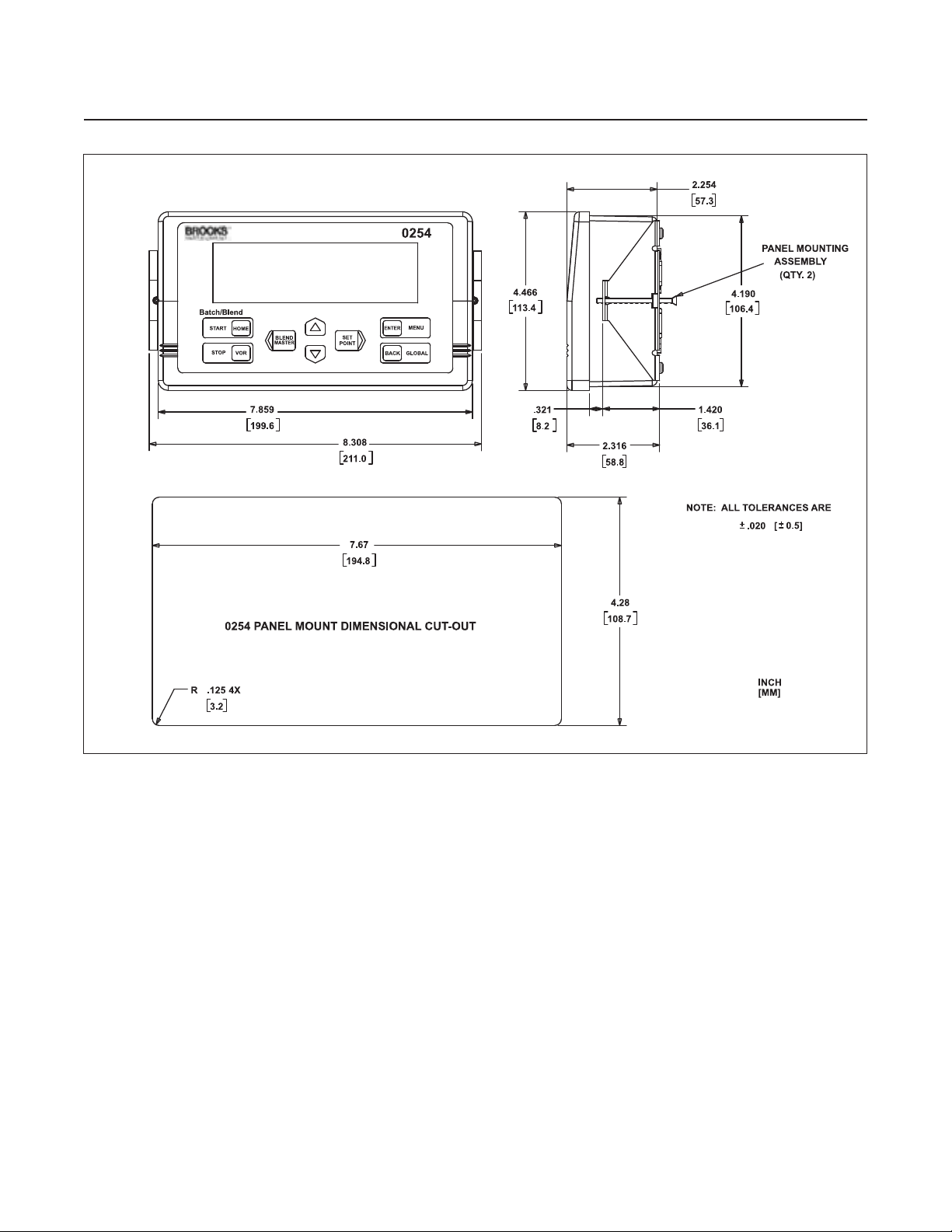
Panel Cut-Out: 7.67 x 4.275 in., 0.125 in. radius maximum
(194.8 x 108.6 m, 3.2 m radius maximum); 0.25 in. (6.35 mm) maximum
panel thickness with optional panel mount kit
Certifications
CE Mark: EN61326-1
FCC: Part 15 Class A, Part 68
RoHS: EPD 2002/95/EC, 01Jul2006
UL: UL 61010 Electrical Safety for General Purpose
Indoor Use;
Altitude up to 2000 m;
RA TED POLLUTION Degree 2
1-5
Page 14

Section 1 Introduction
Model 0254
Installation and Operation Manual
X-SE-0254-eng
Part Number: 541B129AAG
September, 2010
Mounting Options
Panel Mount Kit: Brackets accept panel thickness up to 0.25 in. (6.35 mm)
T able T op Kit: W eighted base with fixed tilt for easy viewing
Rack Mount Kit: Hardware for mounting the Model 0254 and optional power
supply into 19-in. sub-rack.
Rack Mount Kit with 19-in. sub-rack: 19-in. sub-rack included with Rack
Mount Kit
Retrofit Applications, Model 0152/0154: Rack Mount Kit will adapt the
Model 0254 and power supply to the table top enclosure used for the
Model 0152/0154
Communications
Full communications capability for remote readout setpoint, control,
programming, and data acquisition
1-3 Signal Wiring
NOTES:
1) The following nodes are directly connected inside the 0254:
Pin 12 (COM PWR) of each DA15S channel
Pin 5 (GND) of the SERIAL PORT connector
Pins 1,2 and 6 (GND) of the +12-24 Vdc 9-Pin SUB D connector
All hex shield screwlocks for all SUB-D connectors
2) For each DA15S channel, Pins 6 (CMD RTN) and 8 (RATE RTN) are directly connected,
are connected via approximately 10KΩ to Pin 12 (COM PWR)
Pins 6 and 8 are not directly connected between channels
3) For all connectors, all unlisted pins are not internally connected
Figure 1-1 Model 0254 Signal Wiring
1-6
Page 15

Installation and Operation Manual
X-SE-0254-eng
Part Number: 541B129AAG
September, 2010
1-4 Optional Equipment
1-4-1 Mounting Kit Options
1-4-2 Power Supply Options
Section 1 Introduction
Model 0254
The Model 0254 can be mounted using the following kits:
• Panel Mount Kit
• T able Top Kit
• Rack Mount Kit
• Rack Mount Kit with 19-in. Rack
The Model 0254 supports the following power supply options:
1-4-3 Input/Output Pin-Out Adapters
• Factory supplied: +15 Vdc/2 A, –15 Vdc/1 A, 100–240 Vac, 47–63 Hz
• Factory supplied: +24 Vdc/2.5 A, 100–240 Vac, 47–63 Hz
• User supplied: 12–24 Vdc into 9-pin D connector, 5 A rated
The Model 0254 has four 15-pin female D-channel connectors. The pin
configuration is compatible with standard Brooks 0(4)-20 mA cables.
An optional pin-out adapter kit with four adapters is available for use with
Brooks 0(1)-5 Vdc cables.
1-7
Page 16

Section 1 Introduction
Model 0254
Installation and Operation Manual
X-SE-0254-eng
Part Number: 541B129AAG
September, 2010
THIS PAGE WAS
INTENTIONALLY
LEFT BLANK
1-8
Page 17

X-SE-0254-eng
Part Number: 541B129AAG
September, 2010
2-1 General
2-2 Receipt of Equipment
Section 2 InstallationInstallation and Operation Manual
Model 0254
This section provides installation instructions for the Model 0254 Gas and
Liquid Mass Flow Secondary Electronics device.
When the instrument is received, the outside packing case should be
checked for damage incurred during shipment. If the packing case is
damaged, the local carrier should be notified at once regarding his liability .
A report should be submitted to your nearest Product Service Department.
Brooks Instrument
407 W. V ine Street
P.O. Box 903
Hatfield, PA 19440 USA
Toll Free (888) 554 FLOW (3569)
Tel (215) 362 3700
Fax (215) 362 3745
E-m ail: BrooksAm @BrooksInstrument.com
www.BrooksInstrument.com
2-3 Recommended Storage Practice
Brooks Instrument Brooks Instrument
Neonstraat 3 1-4-4 Kitasuna Koto-Ku
6718 WX Ede, Netherlands Tokyo, 136-0073 Japan
P.O. Box 428 Tel +81 (0) 3 5633 7100
6710 BK Ede, Netherlands Fax +81 (0) 3 5633 7101
Tel +31 (0) 318 549 300 Email: BrooksAs@BrooksInstrument.com
Fax +31 (0) 318 549 309
E-mail: BrooksEu@BrooksInstrument.com
Remove the envelope containing the packing list. Carefully remove the
instrument from the packing case. Make sure spare part s are not
discarded with the packing materials. Inspect for damaged or missing
parts.
If intermediate or long-term storage of equipment is required, it is
recommended that the equipment be stored in accordance with the
following:
• Within the original shipping container.
• Stored in a sheltered area, preferably a warm, dry, heated warehouse.
• –40 to 185°F (–40 to 85°C); 0 to 95% non-condensing.
• Upon removal from storage, a visual inspection should be conducted to
verify the condition of equipment is "as received".
2-1
Page 18

Section 2 Installation Installation and Operation Manual
X-SE-0254-eng
Part Number: 541B129AAG
Model 0254
2-4 Return Shipment
Prior to returning any instrument to the factory, cont act your nearest Brooks
location for a Return Materials Authorization Number (RMA#). This can be
obtained from one of the following locations:
Brooks Instrument
407 W. Vi ne Street
P.O. Box 903
Hatfield, PA 19440 USA
Toll Free (888) 554 FLOW (3569)
Tel (215) 362 3700
Fax (215) 362 3745
E- mail: BrooksA m@BrooksInstrument.com
www.BrooksInstrument.com
Brooks Instrument Brooks Instrument
Neonstraat 3 1-4-4 Kitasuna Koto-Ku
6718 WX Ede, Netherlands Tokyo, 136-0073 Japan
P.O. Box 428 Tel +81 (0) 3 5633 7100
6710 BK Ede, Netherlands Fax +81 (0) 3 5633 7101
Tel +31 (0) 318 549 300 Email: BrooksAs@BrooksInstrument.com
Fax +31 (0) 318 549 309
E-mail: BrooksEu@BrooksInstrument.com
September, 2010
2-5 Transit Precautions
To safeguard against damage during transit, transport the instrument to the
installation site in the same container used for transportation from the
factory if circumstances permit.
2-6 Removal from Storage
Upon removal from storage, a visual inspection should be conducted to
verify the condition of the equipment is “as received.”
2-7 Ventilation and Mounting Requirements
Because of the low power consumption of the Model 0254, it does not
have ventilation requirements. However , the ambient temperature
surrounding the Model 0254 should not exeed 122°F (50°C). The optional
power supply modules are also ventilation-free and limited to an ambient
temperature of 122°F (50°C).
2-8 Cleaning Instructions
Do not use cleaning agents other than water because this might affect
color and marking of the equipment.
2-2
Use a clean, soft and damp cloth for cleaning.
Page 19

X-SE-0254-eng
Part Number: 541B129AAG
September, 2010
2-9 Cable Requirements
2-10 Installation Instructions
Section 2 InstallationInstallation and Operation Manual
Model 0254
For compliance with the EMC directive 89/336/EEC, the equipment has to
be installed with shielded signal cables which are overall completely
screened with a shield of at least 80%. Sub-D connectors used must be
shielded with a metal shield. The cable screen should be connected to the
metal shell and shielded at both ends over 360°. The shield should be
terminated to earth ground.
The optional power supplies available from Brooks are always supplied
with a power cord that meets all agency certifications and has a protective
conductor for grounding purposes. Any replacement cords must have
similar construction and be certified by a recognized nartional test
laboratory.
Do not use cleaning agents other than water because this might affect
color and marking of the equipment.
2-10-1 Panel Mount Installation Instructions
1. Cut a hole according to the cut-out dimensions shown in Figure 2-1 on
p. 2-4.
2. Pass the Model 0254 enclosure through the cut-out.
3. Position one of the two brackets included in the Panel Mount kit on the
side of the enclosure, while aligning the two holes at the top and bottom
of the bracket flange with the holes at the corners of the back of the
enclosure. Secure the bracket to the enclosure with two of the screws
provided in the kit.
Do not over-tighten these attachment screws.
4. Secure the second bracket to the other side of the enclosure.
5. Tighten the panel mounting screws in the middle of both brackets to
secure the enclosure to the panel.
CAUTION
!
CAUTION
!
Do not over-tighten these attachment screws.
6. Connect the power supply cable with the D-connector to the power
connector on the back of the enclosure.
7. Connect the power supply AC cord to a power outlet.
8. Connect the cables to the RS-232 and Channel connectors, as
approprate for the application.
2-3
Page 20
Section 2 Installation Installation and Operation Manual
X-SE-0254-eng
Part Number: 541B129AAG
Model 0254
September, 2010
Figure 2-1 Panel Mount Cut-Out Dimensions
2-4
Page 21
X-SE-0254-eng
Part Number: 541B129AAG
September, 2010
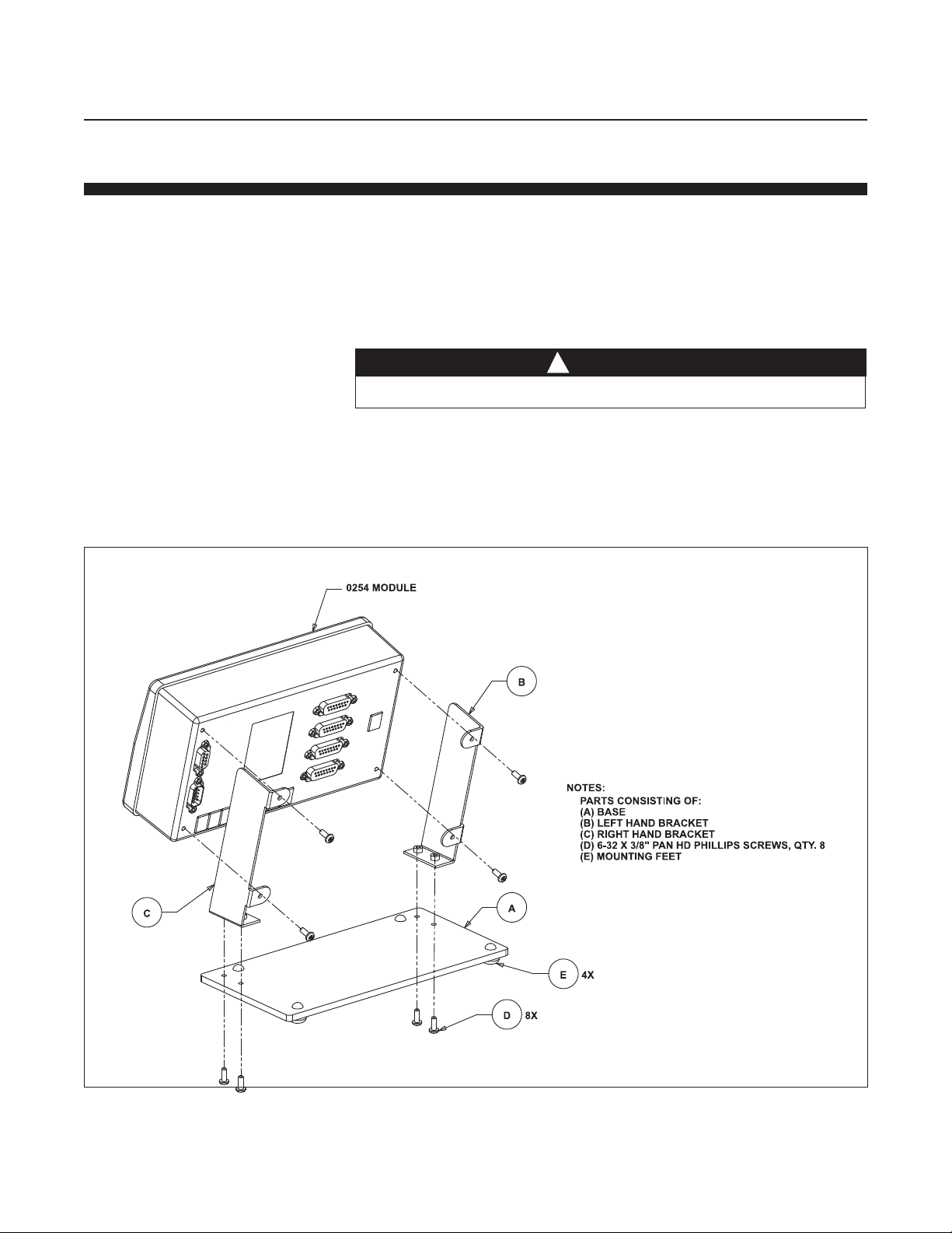
2-10-2 T able T op S t and Assembly Instructions
1. Attach the four rubber mounting feet to the base, as shown in
Figure 2-2.
2. Use four of the provided screws to attach the two brackets to the base.
3. Slide the Model 0254 enclosure into the brackets.
4. Use four screws to secure the enclosure to the brackets.
Do not over-tighten these attachment screws.
5. Connect the power supply cable with the D-connector to the power
connector on the back of the enclosure.
6. Connect the power supply AC cord to a power outlet.
CAUTION
!
Section 2 InstallationInstallation and Operation Manual
Model 0254
7. Connect the cables to the RS-232 and Channel connectors, as
approprate for the application.
Figure 2-2 Table Top Stand Mount Installation
2-5
Page 22

Section 2 Installation Installation and Operation Manual
X-SE-0254-eng
Part Number: 541B129AAG
Model 0254
2-10-3 Retrofit to Model 0152/0154 T able Top Housing
It is possible to retrofit the Model 0254 into a table top box that was used
for the Model 0152/0154.
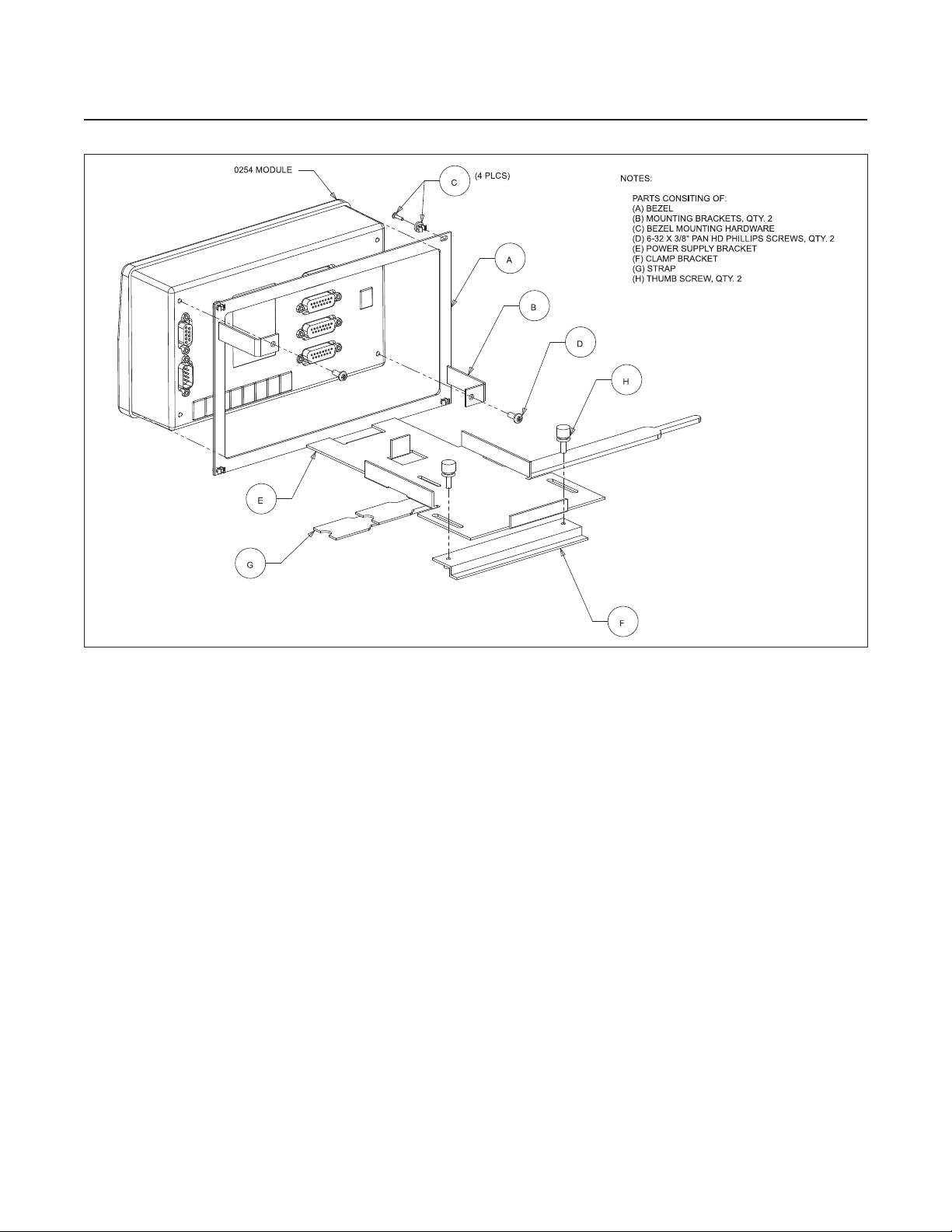
1. Slide the flange on the front of the power supply bracket, shown in
Figure 2-3 on p. 2-8, under the rear channel rail of the box. For an
illustration of the rail engagement, refer to Figure 2-4 on p. 2-9.
2. Use the two thumbscrews at the back of the power supply bracket to
slide the back flange under the front channel rail of the box. Finger
tighten the two thumbscrews.
3. Place the power supply onto the bracket, with the AC cord receptacle
facing the back of the box.
4. Secure the power supply to the bracket using the Velcro strap.
5. Install the four plastic screw retainers into the bezel, then add the bezel
screws.
September, 2010
6. Slide the bezel over the back of the Model 0254 enclosure. Secure the
bezel to the enclosure by threading two screws through the holes in the
bezel mounting brackets and tightening them.
CAUTION
!
Do not over-tighten these attachment screws.
7. Connect the power supply cable with the D-connector to the power
connector on the back of the enclosure.
8. Connect the cables to the RS-232 and Channel connectors, as
approprate for the application.
9. Slide the enclosure into the box until the bezel is flush with the front of
the box.
10. Secure the bezel to the front of the box using the bezel screws.
1 1.Connect the power supply AC cord to a power outlet.
2-6
Page 23

X-SE-0254-eng
Part Number: 541B129AAG
September, 2010
2-10-4 19-in. Rack Assembly and Inst allation Instructions
Use these instructions whether you are installing the Model 0254 into your
own rack or into the optional 19-in. rack assembly from Brooks Instrument.
1. The optional 19-in. rack comes with a blind front plate covering half of
the rack. This plate can be removed or repositioned, depending on the
application, such as installing two Model 0254 modules side by side.
2. Slide the flange on the front of the power supply bracket, shown in
Figure 2-3 on p. 2-8, under the rear channel rail of the rack.
3. Use the two thumbscrews at the back of the power supply bracket to
slide the back flange under the back channel rail of the rack. Finger
tighten the two thumbscrews.
4. Place the power supply onto the bracket, with the AC cord receptacle
facing the back of the box.
5. Secure the power supply to the bracket using the Velcro strap.
Section 2 InstallationInstallation and Operation Manual
Model 0254
6. Install the four plastic screw retainers into the bezel, then add the bezel
screws.
7. Slide the bezel over the back of the Model 0254 enclosure. Secure the
bezel to the enclosure by threading two screws through the holes in the
bezel mounting brackets and tightening them.
CAUTION
!
Do not over-tighten these attachment screws.
8. Connect the power supply cable with the D-connector to the power
connector on the back of the enclosure.
9. Connect the cables to the RS-232 and Channel connectors, as
approprate for the application.
10. Place the enclosure into the rack until the bezel is flush with the
front of the rack.
1 1.Secure the bezel to the front of the rack using the bezel screws.
12. Connect the power supply AC cord to a power outlet.
Figure 2-4 on p. 2-9 shows a completed rack installation.
2-7
Page 24
Section 2 Installation Installation and Operation Manual
X-SE-0254-eng
Part Number: 541B129AAG
Model 0254
September, 2010
Figure 2-3 Power Supply Bracket and Bezel
2-8
Page 25

X-SE-0254-eng
Part Number: 541B129AAG
September, 2010
Section 2 InstallationInstallation and Operation Manual
Model 0254
Figure 2-4 Rack Installation
2-9
Page 26

Section 2 Installation Installation and Operation Manual
X-SE-0254-eng
Part Number: 541B129AAG
Model 0254
September, 2010
THIS PAGE WAS
INTENTIONALLY
LEFT BLANK
2-10
Page 27
Installation and Operation Manual
X-SE-0254-eng
Part Number: 541B129AAG
September , 2010
3-1 Home Screen
Section 3 Operation
Model 0254
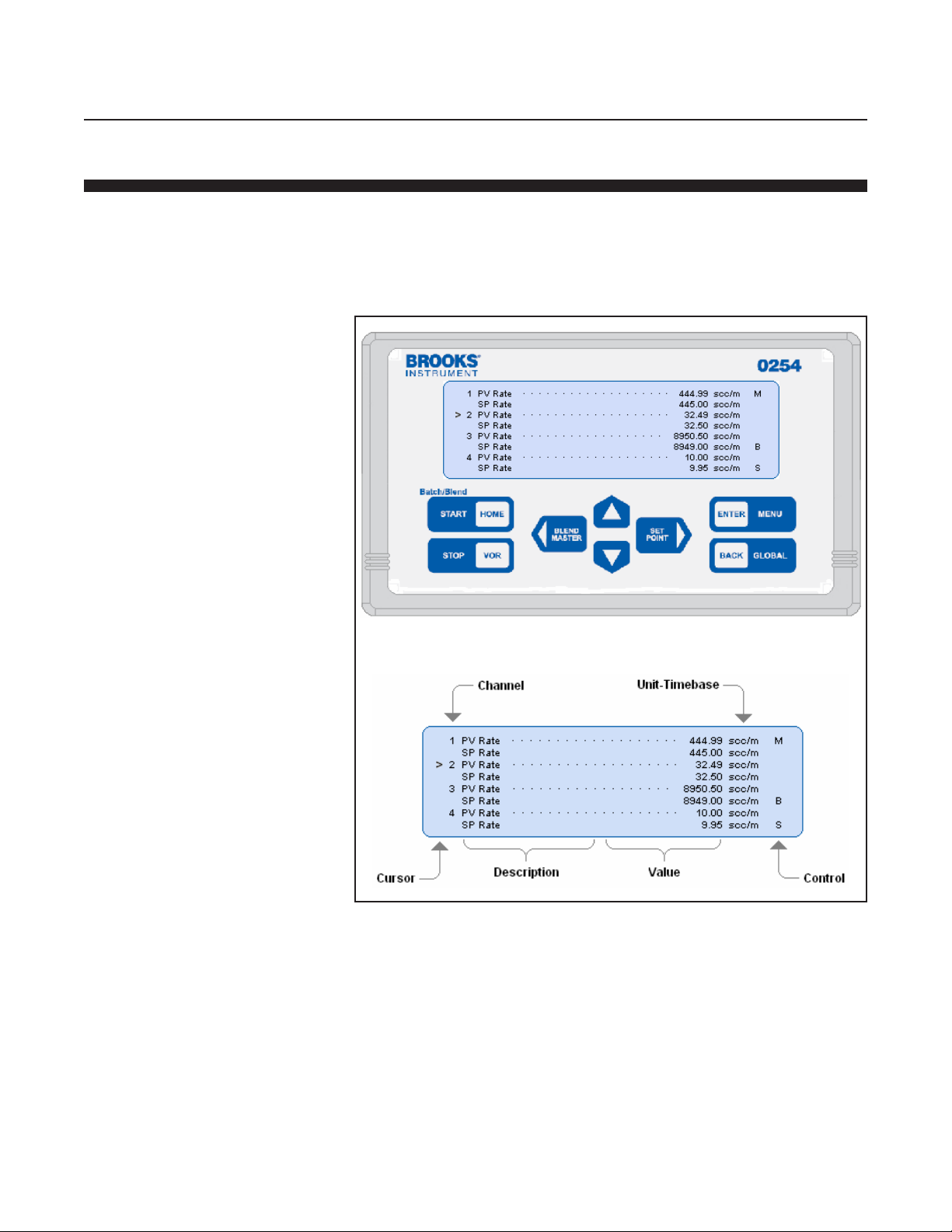
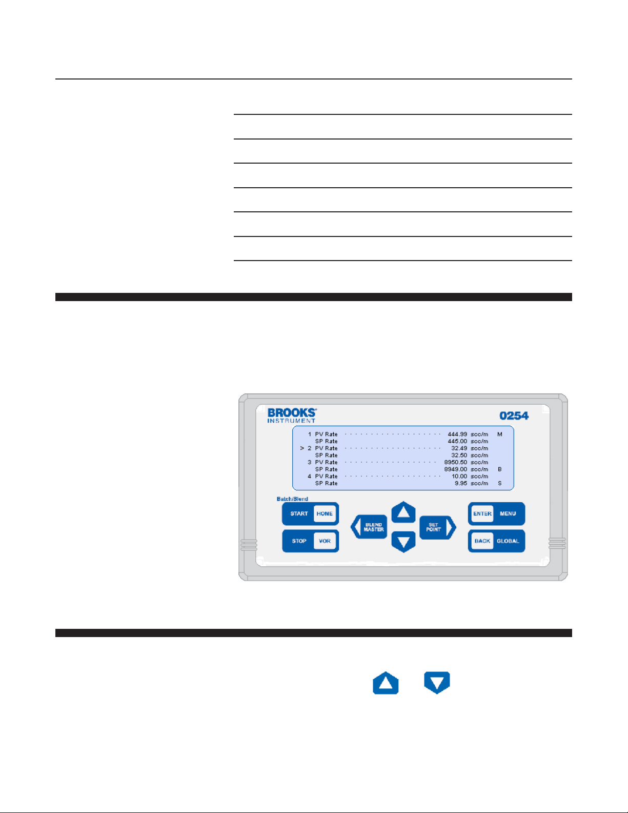
The Model 0254 home screen is the instrument's central information and
navigation indicator. The home screen displays following initial power
application, and automatically follows the make-model screen banner. It
provides an overall view of the instrument's operation. Table 3-1 on p. 3-2
describes the main elements of the home screen.
Figure 3-1 Home Screen
3-1
Page 28
Section 3 Operation
Model 0254
3-2 Operating Controls
Installation and Operation Manual
X-SE-0254-eng
Part Number: 541B129AAG
September, 2010
Table 3-1 Display Home Screen Fields
Cursor Points to channel even when channel is Off.
Channel Numbers 1-4.
Description Process value text.
Value Numeric process value.
Unit / Time-base Combined measure units and rate time-base.
Control Process control state indicators.
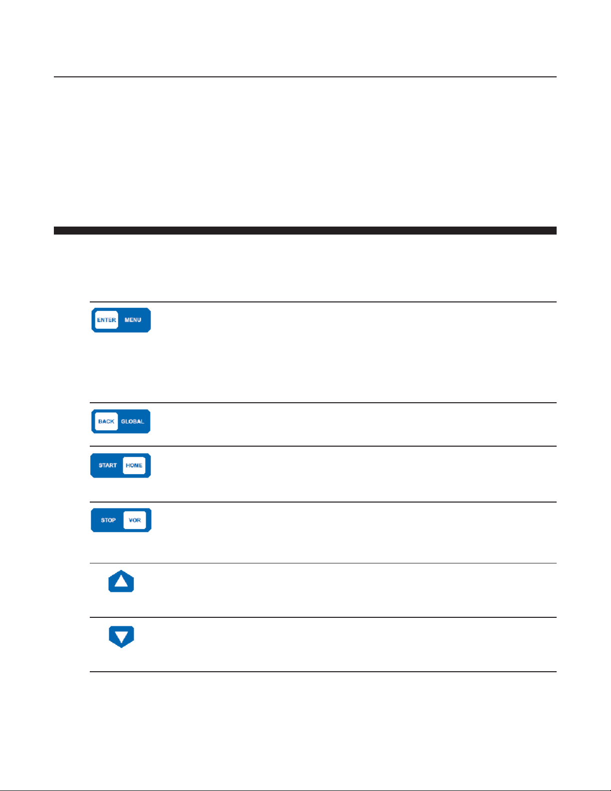
The primary instrument control is supported by eight front panel tactile
snap-action keys, and alternatively by serial communications. Every
function that can be accomplished by using the keys can also be
simultaneously be accomplished by serial communication commands. The
serial communication functions are described more fully in Section D.
3-2-1 Primary Functions
3-2
Primary functions performed from the Home screen are as follows:
• Select a channel using the and keys
• Enter the configuration selection menu
• Enter the Global System Settings selection menus
Page 29
Installation and Operation Manual
X-SE-0254-eng
Part Number: 541B129AAG
September , 2010
3-2-2 Key Functions
Key Present Location System Response
Home Screen Navigates to channel configuration screen.
Section 3 Operation
Model 0254
• Quickly navigate to setpoint or valve override functions
• Start and stop control functions
• Select a blend control master
• Execute the emergency stop function
Instructions for the using the above are described in their respective
subsections throughout this section.
The control function of the keys is dependant on the context of the function
that has been requested to be accomplished as follows:
Function Select Screen Selects viewing configuration or programming
configuration.
Display Configuration Screen Selects the home screen value.
Input Configuration Screen Programs the value that the cursor points to and
saves the value.
Home Screen Press three times to enter Global System Settings.
All Other Screens Navigates immediately to previous screen.
Home Screen Press three times to start batch and/or blend controls
operation.
Power Down Condition Press to restore power.
Home Screen Terminates operating controls if any. Otherwise HOT
navigates to change channel VOR state. This key can
be used to power down the system when pressed for
3 seconds.
All Screens Move cursor up to desired item.
All Screens: Selected Item Increase blinking program selection to succeeding
choice.
All Screens Move cursor down to desired item.
All Screens: Selected Item Decrease blinking program selection to preceding
choice.
3-3
Page 30

Section 3 Operation
Model 0254
Key Present Location System Response
3-3 Navigation
Installation and Operation Manual
X-SE-0254-eng
Part Number: 541B129AAG
September, 2010
All Screens: Selected Item Move cursor left.
Home Screen Select channel pointed to by cursor as blend master
unless the channel is already the master, in which
case the existing master is deselected and no master
is chosen.
Display Configuration Screen Zero PV Total when cursor points to PV Total.
Program Screen Move blinking program selection to next left choice.
All Screens: Selected Item Move cursor right.
Home Screen HOT navigates to change channel setpoint value.
This subsection provides an overview of the various values that are
available to set up the various program values, which determine how the
instrument is desired to perform. It also describes the performance
operating states.
Navigation is primarily performed using the keypad controls described in
"3-2-1 Primary Functions" on p. 3-2. The same operating characteristics
set using the keypad are also fully supported by serial communication. The
serial communication functions are described more fully in Section D.
A complete map of the user interface screens is provided to support the
overview of the instrument. It shows the entire organization of all of the
instrument process values (PV), all setpoint (SP) values, and all system
global settings.
3-4
Page 31

Installation and Operation Manual
X-SE-0254-eng
Part Number: 541B129AAG
September , 2010
3-3-1 Display or Instrument Configuration Screen Selection
Pressing the menu button from the Home screen provides a secondary
navigation layer for the operator to specify whether PV-SP Display
Configuration or PV-SP Instrument Configuration is desired for a channel.
The screen shown below is displayed as a result of having pressed the
ENTER key while viewing the home screen.
This screen shown is for Channel 2. Use the cursor keys to point to either
Display Configuration to show the present PV Measurements and SP
Status, or Instrument Configuration to program PV and SP values, and
then press ENTER to proceed to the desired selection.
Section 3 Operation
Model 0254
3-5
Page 32

Section 3 Operation
Model 0254
3-3-2 User Interface Screen Map
Installation and Operation Manual
X-SE-0254-eng
Part Number: 541B129AAG
September, 2010
The following diagram showing the screen mapping from the home page to
the channel values.
Figure 3-2 User Interface Screen Map
3-6
Page 33

Installation and Operation Manual
X-SE-0254-eng
Part Number: 541B129AAG
September , 2010
3-4 Process Values (PV) and Setpoint s (SP)
This subsection provides a detailed description of the various system map
values that are used to set up the instrument's desired operating
characteristics. These characteristics establish how the instrument is
desired to perform. The subsection also covers the various process values,
which are the outcome of the setup, that show the operating state.
3-4-1 PV-SP Measures and S t atus
Section 3 Operation
Model 0254
The present PV and SP values shown on the home screen are indicated by
an asterisk (*) prefix.
To change the PV displayed on the home screen, point the cursor to the
desired PV value and press the ENTER key.
To change the SP displayed on the home screen, point the cursor to the
desired SP value and press the ENTER key.
For both PV and SP, note that the star indicator is now prefixed to a new
PV or SP value.
PV Rate
This value is either a Rate, defined as quantity per unit time, or None,
which is a scalar value not having a time associated attribute. The Rate
and Time base are configured in the Channel Instrument Configuration
screen. A Time base value must be configured for the totalizer function to
operate. The value displayed is updated in real time as the value changes.
PV T otal
This is a quantity accumulator for a rate value. The quantity values are
displayed when the channel time base is NOT programmed for None. PV
Total quantity is not accumulated for None values, and no PV Total will be
shown on the screen. The value displayed is updated in real time as the
value changes.
To clear an accumulated quantity to zero, point the cursor to PV Total and
press the key. Note the value becomes zero.
3-7
Page 34

Section 3 Operation
Model 0254
3-4-2 PV-SP Configuration
Installation and Operation Manual
X-SE-0254-eng
Part Number: 541B129AAG
September, 2010
PV Signal
This value is the measured electrical value being input into the instrument
channel. It may be used to provide assistance in system installations, and
is used to support instrument calibration. The value displayed is updated in
real time as the value changes.
SP Setpoints
Separate setpoints are provided for rate control (SP Rate), Batch quantity
(SP Batch), and Blend proportion (SP Blend). The specific setpoint shown
on the screen is dependant on the SP Function control type that has been
selected. The value displayed is updated in real time as the value changes.
SP Signal
This value is the output signal being sent form the instruments channel,
and is expressed in the appropriate analog signal type units of V olts or mA.
The PV and SP channel configuration allows you to program the channel
values to determine how signal inputs and outputs are displayed,
calculated, operated, and scaled. These values are programmed in the
Channel Instrument Configuration screen. For more information, refer to
"3-6 Process Controls" on p. 3-15, which describes in greater detail the
setup, configuration, operation, and termination of control processes.
The PV and SP program values are used to determine the following
channel attributes:
• Gas type service
• Channel override signal
• PV signal type and full scale range
• SP signal type and full scale range
• Channel service function
• Channel override signal
• SP values
• SP programming source
The PV and SP values are static and are updated only after a value has
been changed and saved.
3-8
Page 35

Installation and Operation Manual
X-SE-0254-eng
Part Number: 541B129AAG
September , 2010
3-4-3 Value Programming
Section 3 Operation
Model 0254
Program a value by pointing the cursor to its line and pressing the ENTER
key . Note a character or string (character string) will be blinking, ready to
be edited.
Edit the character string as follows:
1. Change character string to next value key or previous value key.
2. Move blinking character-string edit field left keyor right key
3. Press the ENTER key to save the changed value (any other key causes
the edited value to be ignored and not saved) and the original value to
be edited will remain unchanged.
When editing a character field that is blinking, the program state will be
terminated if a key is not detected within 30 seconds of the last detected
key . In this case, the value edited will not be saved, and the original value
to be edited will remain unchanged.
Measure Units
Measure units are a combination of symbols used to identify a physical
engineering measurement. The measure units may be selected from a
fixed set of customary strings. Measure Units have no arithmetic affect.
Supported measure units are listed in Section A.
Time Base
This selection is used to set the quantity per unit time (rate) measurement
as either Sec, Min, Hrs, or Days and None. The None, or scalar, time base
selection is presumed not to have a time-quantity association and does not
perform quantity accumulation.
3-9
Page 36

Section 3 Operation
Model 0254
Installation and Operation Manual
X-SE-0254-eng
Part Number: 541B129AAG
September, 2010
Decimal Point
The decimal point for values may be freely selected for none, one, two, or
three places. The decimal sets the number of measurement value digits
that are to the right of the decimal point. Setting the decimal has an
arithmetic function that, when changed, automatically multiplies or divides
an existing value so values continue to retain their power-of-ten value. The
values so affected include PV and SP Full Scale, SP Rate, SP Batch.
Gas Factor
This value is a unit-less factor by which measured PV Signals are
compensated by multiplication, and SP Signals corrected by division. This
instrument performs the arithmetic compensation using the Gas Factor.
This capability makes it possible to compensate other gases that are not
the calibration gas. However, the existing Gas Factor must be known and
then methodically changed. By knowing the present factor for the
calibration gas, and desiring to control known gases for which an attached
TMF has not been calibrated, then just divide the new gas factor by the
previously known calibrated gas factor. The result becomes the new Gas
Factor.
Log T ype (Future Option)
All logging option selections should be set to Off.
PV-SP Signal T ypes
Signal Selections May be set for full scale ranges which include
0–20 mA, 4–20 mA, 0–5 V, 1–5 V, 0–10 V,
2–10 V, or OFF.
OFF selection Suspends service for either or both channel PV
and SP signals. Inactive OFF is indicated on the
home screen as a blank line.
PV- SP Full Scale
This value sets the maximum engineering unit range over which the Signal
Type is valid. The minimum is always presumed to be zero.
SP Function
The allowable setpoint Functions are Rate, Batch, or Blend.
Rate The value set in SP Rate is converted to a
corresponding analog signal, which is directly
sent to the channel analog signal output. Refer to
"3-6-1 Rate Control/Setpoint Control" on p. 3-15
for more details.
3-10
Page 37

Installation and Operation Manual
X-SE-0254-eng
Part Number: 541B129AAG
September , 2010
Section 3 Operation
Model 0254
Batching Batching is a discontinuous control process that
delivers the quantity set in the SP Batch. This
process is started using either the keypad or a
serial communication command. Batching is
terminated when the desired batch quantity has
been delivered, or any time before delivery is
complete by pressing the STOP. Refer to "3-6-3
Batch Control" on p. 3-18 for more details.
Blending Blending is a continuous control process after
having been started that delivers a rate
proportion set in the SP Blend register, which is
referred to as the prevailing Blend Master input
rate. This process is started using either the
keypad or a serial communication command.
Blending is terminated any time by pressing the
STOP key from the home screen. Refer to "3-6-4
Blend Control" on p. 3-19 for more details.
SP VOR (Valve Override)
This value is set to Normal for standard TMF operation. VOR Normal
causes a VOR signal output voltage to be disconnected (i.e., floating). The
VOR function is used in TMF applications to override the normal analog
command signals, and is used for installation and system diagnostic
purposes.
Valve Open The VOR output signal is connected and
provides a voltage > 8.0 Vdc, causing the TMF
valve to be fully open.
Valve Closed The VOR output signal is connected and
provides a voltage < –4.0 Vdc, causing the TMF
valve to be fully closed.
SP Source
This control enables selection of the source from which setpoints may be
entered as either Keypad or Serial. When set for Serial,changing a setpoint
using the keypad is prohibited.
3-11
Page 38

Section 3 Operation
Model 0254
3-5 Global Settings
3-5-1 Global Information
Installation and Operation Manual
X-SE-0254-eng
Part Number: 541B129AAG
September, 2010
Global settings are the various system wide variables used to set up and
review the overall operating characteristics that establish how the entire
instrument will perform. The values include those provided only for viewing,
those that can be selected, and those that invoke immediately action.
To access the Global Settings screen, press the BACK/GLOBAL key three
times from the Home screen.
This screen contains system information values and configuration states.
These values are not programmable, with the only exception being the
Factory Set immediate action selection described below , which erases
present programmed values and replaces them with factory default values.
NOTE: The Clk Install, Wan Install, and Lan Install settings are not available for use.
Unit Serial Number
This is a factory-entered manufacturing serial number and does not relate
directly to the device serial number.
Version
This is the date the firmware was last upgraded represented as year,
month, and day , and is only for viewing.
3-12
Page 39

Installation and Operation Manual
X-SE-0254-eng
Part Number: 541B129AAG
September , 2010
3-5-2 Global System Power
Section 3 Operation
Model 0254
Check Sum
This value is the hexadecimal double word sum of the instruction read-only
memory used for factory quality assurance, and is only for viewing.
Factory Set
When the cursor is pointing to Factory Set, a pop-up warning displays
“WARNING - ENTER erases program values” at the bottom of the display.
Pressing ENTER will cause all user program values to be erased and overwritten with factory standard default values. Factory Set does NOT erase
factory pre-set calibration values, which continue to be retained.
To enter the System Power function, point the cursor to System Power on
the Global Settings screen and press the ENTER key . This is an immediate
action selection.
The System Power functions causes power to equipment connected to the
instrument to placed in an Off state, allowing the user to conduct
installation services and diagnostics. The power-of f state is also useful for
placing the instrument and connected equipments in an un-powered
dormant state when the instrument is expected to remain unused for
extended periods.
The pop-up at the bottom of the display is shown on the screen only when
the cursor is pointing to System Power .
Power OFF Press the ENTER key with the cursor pointing to
System Power. This will cause entry into the
power down state, the screen to become blank
with its back-light off, and all signals and power
to be removed from connected equipment.
Power ON Press the START key to restore normal system
operation.
3-13
Page 40

Section 3 Operation
Model 0254
3-5-3 Global Control Services
Installation and Operation Manual
X-SE-0254-eng
Part Number: 541B129AAG
September, 2010
To enter the Control Services screen, point the cursor to Control Services
on the Global Settings screen and press the ENTER key .
These Control Service settings are programmable but are not updated in
real time. They establish operation of the several system level operating
controls.
Audio Beep When this control is selected ON, allows normal
audio annunciation for alarms and key
activation. Otherwise, all audio indications
remain disabled.
Zero Suppress When this control is selected ON, numeric
measured values are displayed with leading
zeros suppressed.
Pwr SP Clear When this control is selected ON, power
restoration causes every channel SP value to
be erased and made zero. Any VOR setting will
be returned to normal.
3-14
Page 41

Installation and Operation Manual
X-SE-0254-eng
Part Number: 541B129AAG
September , 2010
3-5-4 Global Communication
Section 3 Operation
Model 0254
To enter the Communications service screen, point the cursor to
Communications on the Global Settings screen and press the ENTER key .
The Network Addr (address) is shown on the service screen. The Network
Address is a unique identification for the instrument operating in a network
environment. It is factory pre-set and not customer programmable.
3-6 Instrument Confugration and Control
This subsection provides a detailed description of the instrument's Rate,
Batch, and Blend control functions, and the channel configuration for the
SP and PV signals.
3-6-1 Rate (Setpoint) Control
Rate control is a continuous process performed on a channel-by-channel
basis.
To configure Rate control:
1. Position the cursor pointing towards the appropriate channel on the
2. Press the Enter/Menu key , and select Instrument Configuration by
3. Once in the Instrument Configuration screen, scroll down to the SP
Home screen.
pressing the Enter/Menu key .
Function option and select Rate.
3-15
Page 42

Section 3 Operation
Model 0254
Installation and Operation Manual
X-SE-0254-eng
Part Number: 541B129AAG
September, 2010
4. Scroll down to the SP Rate option and select the flow rate setpoint that
is desired. This control type causes an SP Rate signal programmed by
the operator to be output to a controller . The setpoint can also be
programmed by the Setpoint hot key .
Start Rate Control
To start rate control, a setpoint must be provided. To set setpoint, use the
Setpoint hot key or the Instrument Configuration screen.
Home Screen
The delivery process can be monitored as shown on the real-time updated
screens above and below . Observing that the SP Rate is the same as the
monitored PV Rate.
3-16
Page 43

Installation and Operation Manual
X-SE-0254-eng
Part Number: 541B129AAG
September , 2010
3-6-2 PV Configuration
Section 3 Operation
Model 0254
T erminate Rate Control
When the channel SP Rate is set to zero, the process is off.
To set setpoint to zero, use the Setpoint hot key or the Instrument
Configuration screen.
Independently , the controller's output signal is monitored and indicated as
the channel PV Rate, PV Signal, or PV Total, as selected in the Display
Configuration screen. The PV Signal Type and PV Full Scale values are
configured in the channel instrument configuration. Rate is a continuous
process performed on a channel-by-channel basis.
To configure the PV Signal Type and PV Full Scale values:
1. Position the cursor pointing towards the appropriate channel on the
Home screen.
2. Press the ENTER/MENU key.
3. Select Instrument Configuration by pressing the ENTER/MENU key .
4. Once in the Instrument Configuration screen, scroll down to the PV
Signal Type and PV Full Scale options and select the applicable PV
Signal Type and PV Full Scale values that are desired.
3-17
Page 44

Section 3 Operation
Model 0254
3-6-3 Batch Control
Installation and Operation Manual
X-SE-0254-eng
Part Number: 541B129AAG
September, 2010
Batch processing is a non-continuous process that is started, conducted,
and terminated when a desired quantity has completed delivery . You can
stop batch delivery at any time prior to completion.
Setup
The following items must be programmed as follows:
SP Function Select Batch
SP Rate Set desired batch delivery rate
SP Batch Set desired delivery quantity
Start Batch
Return to the home screen. Note that the home screen indicates a ‘B’
control indicator for all channels selected to perform batching.
Home Screen
Press the ST AR T key three times. ‘B’ indicators will be blinking to indicate
channels with batch now in process.
3-18
The delivery process can be monitored as shown on the screen below by
observing that the PV Total increases toward the SP Batch amount, and
verifying that the PV Rate properly indicates the desired delivery rate. The
values in this screen are updated in real time. If the SP Function is set for
Batch, the SP Batch quantity appears on this screen.
Page 45

Installation and Operation Manual
X-SE-0254-eng
Part Number: 541B129AAG
September , 2010
Section 3 Operation
Model 0254
T erminate Batches
Batching for each channel set for batch will automatically terminate when
each batch channel PV Total has reached or exceeded its programmed SP
Batch setpoint.
Y ou can terminate any channels that continue with batching remaining in
process by first returning to the home screen, then pressing the STOP key
once. Note that the ‘B’ control indicators on the home screen stop blinking,
indicating that all batch processes are stopped. Pressing the ST AR T key
three times will always reset all batch totals to zero before starting the
process.
3-6-4 Blend Control
Blending is a continuous process that, when started, causes slave SP
Rates to be a proportion of the actual rate being delivered by the master
rate.
NOTE: Blend parameters are saved when power is lost, allowing blending to continue
after power is restored unless Pwr SP Clear is selected to be ON. Refer to "3-5-3
Global Control Services" on p. 3-14.
Select a master channel and set its delivery SP Rate. One or more slave
channels are then selected, and the process is started from the home
screen. Once started, blending will continue and may ONLY be terminated
by an operator.
3-19
Page 46

Section 3 Operation
Model 0254
3-6-4-1 Blend Control Setup
Installation and Operation Manual
X-SE-0254-eng
Part Number: 541B129AAG
September, 2010
Program the above values for master and slave channels desired to
perform blending.
Select Blend Master
From the home screen, point to a channel desired to be the master and
press the master blend key. This causes the home screen to show an
‘M,’ indicating master channel. If you press the master key again at that
moment, the ‘M’ control indicator will no longer be present—no master is
then selected—and blending will not be conducted.
To de-select a blend master, point to the present master channel and press
the master blend key. Note that the ‘M’ control indicator is no longer
present and the master has been de-selected.
Home Screen
Master Channel Setup
It is recommended that you wait until after the blending setup is complete
before selecting the desired flow rate setpoint to the Master Channel (refer
to "3-6-4-2 Start Blend" on p. 3-21).
To configure the Master Channel for blending:
1. Position the cursor pointing towards the appropriate channel on the
Home screen.
2. Press the ENTER/MENU key.
3. Select Instrument Configuration by pressing the ENTER/MENU key .
4. Once in the Instrument Configuration screen, scroll down to the SP
Function option and select Rate.
5. Scroll down to the SP Rate option and input a zero flow rate setpoint (or
via the Setpoint hot key).
NOTE: If you input a flow rate setpoint other than zero, the Master Channel will
immediately respond to that setpoint and will start to flow.
3-20
Page 47

Installation and Operation Manual
X-SE-0254-eng
Part Number: 541B129AAG
September , 2010
Section 3 Operation
Model 0254
Slave Channels Setup
Navigate to each desired slave channel and set each SP Function to
Blend, then set the desired SP Blend rate percentage referenced to the
master channels actual delivery rate. Note that the home screen shows ‘S,’
indicating selected blend slave channels.
NOTE: Once a slave channel is set to Blend, SP Rate programming is prohibited for
both keypad and serial command.
3-6-4-2 Start Blend
1. Return to the Home screen.
2. Press the ST ART key three times. Note the 'M' and 'S' suffix now
blinking to indicate channels with blend now in process.
3. Navigate to the Master Channel Instrument Configuration screen (or via
the Setpoint hot key) and set the Master SP Rate to the desired value.
The blending process is visible on the Home screen, observing that the SP
Rate of the slave channels is the programmed proportion of the master
rate. If desired, the Home screen can be reconfigured to replace SP Rate
of the slave channels with SP Blend ratio, as described in "3-4-1 PV -SP
Measures and Status" on p. 3-7.
3-21
Page 48

Section 3 Operation
Model 0254
3-6-4-3 T erminate Blend In-Process
Once blending has started, it will continue unless manually terminated.
To terminate blending:
1. Return to the Home screen, if not already there, and press the STOP
2. Observe that the 'M' and 'S' process indicators no longer blink.
3. To resume blending, press the START key three times and re-enter the
3-6-5 SP VOR (Valve Override) Function
The SP VOR function is typically used in Mass Flow applications to
override the normal analog command signals for installation and system
diagnostic purposes.
Installation and Operation Manual
X-SE-0254-eng
Part Number: 541B129AAG
September, 2010
key. This resets the master channel SP Rate to zero, which stops all
flow.
setpoint of the master channel, as described in "3-6-4-2 S tart Blend" on
p. 3-21.
The SP VOR function allows operators to either open or close the Mass
Flow Control (MFC) valve independent of the current setpoint value.
The SP VOR function has three available settings.
• The Normal setting is for normal MFC operation in which the valve is
controlled by the selected Setpoint values.
• The Open setting causes the valve to be fully open regardless of
setpoint. This allows operators to purge the system or to force
maximum flow through the MFC.
• The Closed setting causes the valve to be fully closed regardless of
setpoint.
To activate one of the SP VOR function modes:
1. Position the cursor pointing towards the appropriate channel on the
Home screen.
2. Press the ENTER/MENU key.
3. Select Instrument Configuration by pressing the ENTER/MENU key .
4. Once in the Instrument Configuration screen, scroll down to the SP
VOR Function option and select the mode that is desired (Normal,
Open, or Closed). The SP VOR selection can also be accessed directly
by the VOR hot key.
3-22
Page 49

Installation and Operation Manual
X-SE-0254-eng
Part Number: 541B129AAG
September , 2010
Section 3 Operation
Model 0254
Once activated, the SP VOR function mode is shown on the appropriate
channel display to indicate which VOR function mode is active. The setting
of the SP VOR Valve override function is memorized. After power down
and power up, the memorized SP VOR function mode will remain in the
previous mode until it is changed by the operator .
3-6-6 T ot alization
To return to Normal operation after activating one of the SP VOR function
modes:
1. Position the cursor pointing towards the appropriate channel on the
Home screen.
2. Press the ENTER/MENU key.
3. Select Instrument Configuration by pressing the ENTER/MENU key .
4. Once in the Instrument Configuration screen, scroll down to the SP
VOR Function option and select the Normal mode. The SP VOR
selection can also be accessed directly by the VOR hot key .
The Totalizer function is used to provide a total of a selected channel's PV
Output Rate over time. The total is based on the Rate and Time base that
is configured in the particular channel's Instrument Configuration screen. A
Time base value must be configured for the Totalizer function to operate.
To display the Totalizer value:
1. Position the cursor pointing towards the appropriate channel on the
Home screen.
2. Press the ENTER/MENU key.
3. Select Display Configuration by pressing the ENTER/MENU key .
4. Once in the Display Configuration screen, scroll down and select the
PV T ot al option.
3-23
Page 50

Section 3 Operation
Model 0254
3-6-7 Emergency Off
Installation and Operation Manual
X-SE-0254-eng
Part Number: 541B129AAG
September, 2010
5. Once selected, return to the Home screen. The Totalizer value will now
be displayed on the channel PV line. The accumulated quantity value
displayed is updated in real time as the value changes.
To clear or reset an accumulated quantity to zero, point the cursor to PV
Total and press the
key. Note that the value is reset to zero.
To shut down the instrument, press and hold the STOP/VOR button for
three seconds.
3-24
Page 51

Installation and Operation Manual
X-SE-0254-eng
Part Number: 541B129AAG
September , 2010
3-1 Home Screen
Section 3 Operation
Model 0254
The Model 0254 home screen is the instrument's central information and
navigation indicator. The home screen displays following initial power
application, and automatically follows the make-model screen banner. It
provides an overall view of the instrument's operation. Table 3-1 on p. 3-2
describes the main elements of the home screen.
Figure 3-1 Home Screen
3-1
Page 52

Section 3 Operation
Model 0254
3-2 Operating Controls
Installation and Operation Manual
X-SE-0254-eng
Part Number: 541B129AAG
September, 2010
Table 3-1 Display Home Screen Fields
Cursor Points to channel even when channel is Off.
Channel Numbers 1-4.
Description Process value text.
Value Numeric process value.
Unit / Time-base Combined measure units and rate time-base.
Control Process control state indicators.
The primary instrument control is supported by eight front panel tactile
snap-action keys, and alternatively by serial communications. Every
function that can be accomplished by using the keys can also be
simultaneously be accomplished by serial communication commands. The
serial communication functions are described more fully in Section D.
3-2-1 Primary Functions
3-2
Primary functions performed from the Home screen are as follows:
• Select a channel using the and keys
• Enter the configuration selection menu
• Enter the Global System Settings selection menus
Page 53

Installation and Operation Manual
X-SE-0254-eng
Part Number: 541B129AAG
September , 2010
3-2-2 Key Functions
Key Present Location System Response
Home Screen Navigates to channel configuration screen.
Section 3 Operation
Model 0254
• Quickly navigate to setpoint or valve override functions
• Start and stop control functions
• Select a blend control master
• Execute the emergency stop function
Instructions for the using the above are described in their respective
subsections throughout this section.
The control function of the keys is dependant on the context of the function
that has been requested to be accomplished as follows:
Function Select Screen Selects viewing configuration or programming
configuration.
Display Configuration Screen Selects the home screen value.
Input Configuration Screen Programs the value that the cursor points to and
saves the value.
Home Screen Press three times to enter Global System Settings.
All Other Screens Navigates immediately to previous screen.
Home Screen Press three times to start batch and/or blend controls
operation.
Power Down Condition Press to restore power.
Home Screen Terminates operating controls if any. Otherwise HOT
navigates to change channel VOR state. This key can
be used to power down the system when pressed for
3 seconds.
All Screens Move cursor up to desired item.
All Screens: Selected Item Increase blinking program selection to succeeding
choice.
All Screens Move cursor down to desired item.
All Screens: Selected Item Decrease blinking program selection to preceding
choice.
3-3
Page 54

Section 3 Operation
Model 0254
Key Present Location System Response
3-3 Navigation
Installation and Operation Manual
X-SE-0254-eng
Part Number: 541B129AAG
September, 2010
All Screens: Selected Item Move cursor left.
Home Screen Select channel pointed to by cursor as blend master
unless the channel is already the master, in which
case the existing master is deselected and no master
is chosen.
Display Configuration Screen Zero PV Total when cursor points to PV Total.
Program Screen Move blinking program selection to next left choice.
All Screens: Selected Item Move cursor right.
Home Screen HOT navigates to change channel setpoint value.
This subsection provides an overview of the various values that are
available to set up the various program values, which determine how the
instrument is desired to perform. It also describes the performance
operating states.
Navigation is primarily performed using the keypad controls described in
"3-2-1 Primary Functions" on p. 3-2. The same operating characteristics
set using the keypad are also fully supported by serial communication. The
serial communication functions are described more fully in Section D.
A complete map of the user interface screens is provided to support the
overview of the instrument. It shows the entire organization of all of the
instrument process values (PV), all setpoint (SP) values, and all system
global settings.
3-4
Page 55

Installation and Operation Manual
X-SE-0254-eng
Part Number: 541B129AAG
September , 2010
3-3-1 Display or Instrument Configuration Screen Selection
Pressing the menu button from the Home screen provides a secondary
navigation layer for the operator to specify whether PV-SP Display
Configuration or PV-SP Instrument Configuration is desired for a channel.
The screen shown below is displayed as a result of having pressed the
ENTER key while viewing the home screen.
This screen shown is for Channel 2. Use the cursor keys to point to either
Display Configuration to show the present PV Measurements and SP
Status, or Instrument Configuration to program PV and SP values, and
then press ENTER to proceed to the desired selection.
Section 3 Operation
Model 0254
3-5
Page 56

Section 3 Operation
Model 0254
3-3-2 User Interface Screen Map
Installation and Operation Manual
X-SE-0254-eng
Part Number: 541B129AAG
September, 2010
The following diagram showing the screen mapping from the home page to
the channel values.
Figure 3-2 User Interface Screen Map
3-6
Page 57

Installation and Operation Manual
X-SE-0254-eng
Part Number: 541B129AAG
September , 2010
3-4 Process Values (PV) and Setpoint s (SP)
This subsection provides a detailed description of the various system map
values that are used to set up the instrument's desired operating
characteristics. These characteristics establish how the instrument is
desired to perform. The subsection also covers the various process values,
which are the outcome of the setup, that show the operating state.
3-4-1 PV-SP Measures and S t atus
Section 3 Operation
Model 0254
The present PV and SP values shown on the home screen are indicated by
an asterisk (*) prefix.
To change the PV displayed on the home screen, point the cursor to the
desired PV value and press the ENTER key.
To change the SP displayed on the home screen, point the cursor to the
desired SP value and press the ENTER key.
For both PV and SP, note that the star indicator is now prefixed to a new
PV or SP value.
PV Rate
This value is either a Rate, defined as quantity per unit time, or None,
which is a scalar value not having a time associated attribute. The Rate
and Time base are configured in the Channel Instrument Configuration
screen. A Time base value must be configured for the totalizer function to
operate. The value displayed is updated in real time as the value changes.
PV T otal
This is a quantity accumulator for a rate value. The quantity values are
displayed when the channel time base is NOT programmed for None. PV
Total quantity is not accumulated for None values, and no PV Total will be
shown on the screen. The value displayed is updated in real time as the
value changes.
To clear an accumulated quantity to zero, point the cursor to PV Total and
press the key. Note the value becomes zero.
3-7
Page 58

Section 3 Operation
Model 0254
3-4-2 PV-SP Configuration
Installation and Operation Manual
X-SE-0254-eng
Part Number: 541B129AAG
September, 2010
PV Signal
This value is the measured electrical value being input into the instrument
channel. It may be used to provide assistance in system installations, and
is used to support instrument calibration. The value displayed is updated in
real time as the value changes.
SP Setpoints
Separate setpoints are provided for rate control (SP Rate), Batch quantity
(SP Batch), and Blend proportion (SP Blend). The specific setpoint shown
on the screen is dependant on the SP Function control type that has been
selected. The value displayed is updated in real time as the value changes.
SP Signal
This value is the output signal being sent form the instruments channel,
and is expressed in the appropriate analog signal type units of V olts or mA.
The PV and SP channel configuration allows you to program the channel
values to determine how signal inputs and outputs are displayed,
calculated, operated, and scaled. These values are programmed in the
Channel Instrument Configuration screen. For more information, refer to
"3-6 Process Controls" on p. 3-15, which describes in greater detail the
setup, configuration, operation, and termination of control processes.
The PV and SP program values are used to determine the following
channel attributes:
• Gas type service
• Channel override signal
• PV signal type and full scale range
• SP signal type and full scale range
• Channel service function
• Channel override signal
• SP values
• SP programming source
The PV and SP values are static and are updated only after a value has
been changed and saved.
3-8
Page 59

Installation and Operation Manual
X-SE-0254-eng
Part Number: 541B129AAG
September , 2010
3-4-3 Value Programming
Section 3 Operation
Model 0254
Program a value by pointing the cursor to its line and pressing the ENTER
key . Note a character or string (character string) will be blinking, ready to
be edited.
Edit the character string as follows:
1. Change character string to next value key or previous value key.
2. Move blinking character-string edit field left keyor right key
3. Press the ENTER key to save the changed value (any other key causes
the edited value to be ignored and not saved) and the original value to
be edited will remain unchanged.
When editing a character field that is blinking, the program state will be
terminated if a key is not detected within 30 seconds of the last detected
key . In this case, the value edited will not be saved, and the original value
to be edited will remain unchanged.
Measure Units
Measure units are a combination of symbols used to identify a physical
engineering measurement. The measure units may be selected from a
fixed set of customary strings. Measure Units have no arithmetic affect.
Supported measure units are listed in Section A.
Time Base
This selection is used to set the quantity per unit time (rate) measurement
as either Sec, Min, Hrs, or Days and None. The None, or scalar, time base
selection is presumed not to have a time-quantity association and does not
perform quantity accumulation.
3-9
Page 60

Section 3 Operation
Model 0254
Installation and Operation Manual
X-SE-0254-eng
Part Number: 541B129AAG
September, 2010
Decimal Point
The decimal point for values may be freely selected for none, one, two, or
three places. The decimal sets the number of measurement value digits
that are to the right of the decimal point. Setting the decimal has an
arithmetic function that, when changed, automatically multiplies or divides
an existing value so values continue to retain their power-of-ten value. The
values so affected include PV and SP Full Scale, SP Rate, SP Batch.
Gas Factor
This value is a unit-less factor by which measured PV Signals are
compensated by multiplication, and SP Signals corrected by division. This
instrument performs the arithmetic compensation using the Gas Factor.
This capability makes it possible to compensate other gases that are not
the calibration gas. However, the existing Gas Factor must be known and
then methodically changed. By knowing the present factor for the
calibration gas, and desiring to control known gases for which an attached
TMF has not been calibrated, then just divide the new gas factor by the
previously known calibrated gas factor. The result becomes the new Gas
Factor.
Log T ype (Future Option)
All logging option selections should be set to Off.
PV-SP Signal T ypes
Signal Selections May be set for full scale ranges which include
0–20 mA, 4–20 mA, 0–5 V, 1–5 V, 0–10 V,
2–10 V, or OFF.
OFF selection Suspends service for either or both channel PV
and SP signals. Inactive OFF is indicated on the
home screen as a blank line.
PV- SP Full Scale
This value sets the maximum engineering unit range over which the Signal
Type is valid. The minimum is always presumed to be zero.
SP Function
The allowable setpoint Functions are Rate, Batch, or Blend.
Rate The value set in SP Rate is converted to a
corresponding analog signal, which is directly
sent to the channel analog signal output. Refer to
"3-6-1 Rate Control/Setpoint Control" on p. 3-15
for more details.
3-10
Page 61

Installation and Operation Manual
X-SE-0254-eng
Part Number: 541B129AAG
September , 2010
Section 3 Operation
Model 0254
Batching Batching is a discontinuous control process that
delivers the quantity set in the SP Batch. This
process is started using either the keypad or a
serial communication command. Batching is
terminated when the desired batch quantity has
been delivered, or any time before delivery is
complete by pressing the STOP. Refer to "3-6-3
Batch Control" on p. 3-18 for more details.
Blending Blending is a continuous control process after
having been started that delivers a rate
proportion set in the SP Blend register, which is
referred to as the prevailing Blend Master input
rate. This process is started using either the
keypad or a serial communication command.
Blending is terminated any time by pressing the
STOP key from the home screen. Refer to "3-6-4
Blend Control" on p. 3-19 for more details.
SP VOR (Valve Override)
This value is set to Normal for standard TMF operation. VOR Normal
causes a VOR signal output voltage to be disconnected (i.e., floating). The
VOR function is used in TMF applications to override the normal analog
command signals, and is used for installation and system diagnostic
purposes.
Valve Open The VOR output signal is connected and
provides a voltage > 8.0 Vdc, causing the TMF
valve to be fully open.
Valve Closed The VOR output signal is connected and
provides a voltage < –4.0 Vdc, causing the TMF
valve to be fully closed.
SP Source
This control enables selection of the source from which setpoints may be
entered as either Keypad or Serial. When set for Serial,changing a setpoint
using the keypad is prohibited.
3-11
Page 62

Section 3 Operation
Model 0254
3-5 Global Settings
3-5-1 Global Information
Installation and Operation Manual
X-SE-0254-eng
Part Number: 541B129AAG
September, 2010
Global settings are the various system wide variables used to set up and
review the overall operating characteristics that establish how the entire
instrument will perform. The values include those provided only for viewing,
those that can be selected, and those that invoke immediately action.
To access the Global Settings screen, press the BACK/GLOBAL key three
times from the Home screen.
This screen contains system information values and configuration states.
These values are not programmable, with the only exception being the
Factory Set immediate action selection described below , which erases
present programmed values and replaces them with factory default values.
NOTE: The Clk Install, Wan Install, and Lan Install settings are not available for use.
Unit Serial Number
This is a factory-entered manufacturing serial number and does not relate
directly to the device serial number.
Version
This is the date the firmware was last upgraded represented as year,
month, and day , and is only for viewing.
3-12
Page 63

Installation and Operation Manual
X-SE-0254-eng
Part Number: 541B129AAG
September , 2010
3-5-2 Global System Power
Section 3 Operation
Model 0254
Check Sum
This value is the hexadecimal double word sum of the instruction read-only
memory used for factory quality assurance, and is only for viewing.
Factory Set
When the cursor is pointing to Factory Set, a pop-up warning displays
“WARNING - ENTER erases program values” at the bottom of the display.
Pressing ENTER will cause all user program values to be erased and overwritten with factory standard default values. Factory Set does NOT erase
factory pre-set calibration values, which continue to be retained.
To enter the System Power function, point the cursor to System Power on
the Global Settings screen and press the ENTER key . This is an immediate
action selection.
The System Power functions causes power to equipment connected to the
instrument to placed in an Off state, allowing the user to conduct
installation services and diagnostics. The power-of f state is also useful for
placing the instrument and connected equipments in an un-powered
dormant state when the instrument is expected to remain unused for
extended periods.
The pop-up at the bottom of the display is shown on the screen only when
the cursor is pointing to System Power .
Power OFF Press the ENTER key with the cursor pointing to
System Power. This will cause entry into the
power down state, the screen to become blank
with its back-light off, and all signals and power
to be removed from connected equipment.
Power ON Press the START key to restore normal system
operation.
3-13
Page 64

Section 3 Operation
Model 0254
3-5-3 Global Control Services
Installation and Operation Manual
X-SE-0254-eng
Part Number: 541B129AAG
September, 2010
To enter the Control Services screen, point the cursor to Control Services
on the Global Settings screen and press the ENTER key .
These Control Service settings are programmable but are not updated in
real time. They establish operation of the several system level operating
controls.
Audio Beep When this control is selected ON, allows normal
audio annunciation for alarms and key
activation. Otherwise, all audio indications
remain disabled.
Zero Suppress When this control is selected ON, numeric
measured values are displayed with leading
zeros suppressed.
Pwr SP Clear When this control is selected ON, power
restoration causes every channel SP value to
be erased and made zero. Any VOR setting will
be returned to normal.
3-14
Page 65

Installation and Operation Manual
X-SE-0254-eng
Part Number: 541B129AAG
September , 2010
3-5-4 Global Communication
Section 3 Operation
Model 0254
To enter the Communications service screen, point the cursor to
Communications on the Global Settings screen and press the ENTER key .
The Network Addr (address) is shown on the service screen. The Network
Address is a unique identification for the instrument operating in a network
environment. It is factory pre-set and not customer programmable.
3-6 Instrument Confugration and Control
This subsection provides a detailed description of the instrument's Rate,
Batch, and Blend control functions, and the channel configuration for the
SP and PV signals.
3-6-1 Rate (Setpoint) Control
Rate control is a continuous process performed on a channel-by-channel
basis.
To configure Rate control:
1. Position the cursor pointing towards the appropriate channel on the
2. Press the Enter/Menu key , and select Instrument Configuration by
3. Once in the Instrument Configuration screen, scroll down to the SP
Home screen.
pressing the Enter/Menu key .
Function option and select Rate.
3-15
Page 66

Section 3 Operation
Model 0254
Installation and Operation Manual
X-SE-0254-eng
Part Number: 541B129AAG
September, 2010
4. Scroll down to the SP Rate option and select the flow rate setpoint that
is desired. This control type causes an SP Rate signal programmed by
the operator to be output to a controller . The setpoint can also be
programmed by the Setpoint hot key .
Start Rate Control
To start rate control, a setpoint must be provided. To set setpoint, use the
Setpoint hot key or the Instrument Configuration screen.
Home Screen
The delivery process can be monitored as shown on the real-time updated
screens above and below . Observing that the SP Rate is the same as the
monitored PV Rate.
3-16
Page 67

Installation and Operation Manual
X-SE-0254-eng
Part Number: 541B129AAG
September , 2010
3-6-2 PV Configuration
Section 3 Operation
Model 0254
T erminate Rate Control
When the channel SP Rate is set to zero, the process is off.
To set setpoint to zero, use the Setpoint hot key or the Instrument
Configuration screen.
Independently , the controller's output signal is monitored and indicated as
the channel PV Rate, PV Signal, or PV Total, as selected in the Display
Configuration screen. The PV Signal Type and PV Full Scale values are
configured in the channel instrument configuration. Rate is a continuous
process performed on a channel-by-channel basis.
To configure the PV Signal Type and PV Full Scale values:
1. Position the cursor pointing towards the appropriate channel on the
Home screen.
2. Press the ENTER/MENU key.
3. Select Instrument Configuration by pressing the ENTER/MENU key .
4. Once in the Instrument Configuration screen, scroll down to the PV
Signal Type and PV Full Scale options and select the applicable PV
Signal Type and PV Full Scale values that are desired.
3-17
Page 68

Section 3 Operation
Model 0254
3-6-3 Batch Control
Installation and Operation Manual
X-SE-0254-eng
Part Number: 541B129AAG
September, 2010
Batch processing is a non-continuous process that is started, conducted,
and terminated when a desired quantity has completed delivery . You can
stop batch delivery at any time prior to completion.
Setup
The following items must be programmed as follows:
SP Function Select Batch
SP Rate Set desired batch delivery rate
SP Batch Set desired delivery quantity
Start Batch
Return to the home screen. Note that the home screen indicates a ‘B’
control indicator for all channels selected to perform batching.
Home Screen
Press the ST AR T key three times. ‘B’ indicators will be blinking to indicate
channels with batch now in process.
3-18
The delivery process can be monitored as shown on the screen below by
observing that the PV Total increases toward the SP Batch amount, and
verifying that the PV Rate properly indicates the desired delivery rate. The
values in this screen are updated in real time. If the SP Function is set for
Batch, the SP Batch quantity appears on this screen.
Page 69

Installation and Operation Manual
X-SE-0254-eng
Part Number: 541B129AAG
September , 2010
Section 3 Operation
Model 0254
T erminate Batches
Batching for each channel set for batch will automatically terminate when
each batch channel PV Total has reached or exceeded its programmed SP
Batch setpoint.
Y ou can terminate any channels that continue with batching remaining in
process by first returning to the home screen, then pressing the STOP key
once. Note that the ‘B’ control indicators on the home screen stop blinking,
indicating that all batch processes are stopped. Pressing the ST AR T key
three times will always reset all batch totals to zero before starting the
process.
3-6-4 Blend Control
Blending is a continuous process that, when started, causes slave SP
Rates to be a proportion of the actual rate being delivered by the master
rate.
NOTE: Blend parameters are saved when power is lost, allowing blending to continue
after power is restored unless Pwr SP Clear is selected to be ON. Refer to "3-5-3
Global Control Services" on p. 3-14.
Select a master channel and set its delivery SP Rate. One or more slave
channels are then selected, and the process is started from the home
screen. Once started, blending will continue and may ONLY be terminated
by an operator.
3-19
Page 70

Section 3 Operation
Model 0254
3-6-4-1 Blend Control Setup
Installation and Operation Manual
X-SE-0254-eng
Part Number: 541B129AAG
September, 2010
Program the above values for master and slave channels desired to
perform blending.
Select Blend Master
From the home screen, point to a channel desired to be the master and
press the master blend key. This causes the home screen to show an
‘M,’ indicating master channel. If you press the master key again at that
moment, the ‘M’ control indicator will no longer be present—no master is
then selected—and blending will not be conducted.
To de-select a blend master, point to the present master channel and press
the master blend key. Note that the ‘M’ control indicator is no longer
present and the master has been de-selected.
Home Screen
Master Channel Setup
It is recommended that you wait until after the blending setup is complete
before selecting the desired flow rate setpoint to the Master Channel (refer
to "3-6-4-2 Start Blend" on p. 3-21).
To configure the Master Channel for blending:
1. Position the cursor pointing towards the appropriate channel on the
Home screen.
2. Press the ENTER/MENU key.
3. Select Instrument Configuration by pressing the ENTER/MENU key .
4. Once in the Instrument Configuration screen, scroll down to the SP
Function option and select Rate.
5. Scroll down to the SP Rate option and input a zero flow rate setpoint (or
via the Setpoint hot key).
NOTE: If you input a flow rate setpoint other than zero, the Master Channel will
immediately respond to that setpoint and will start to flow.
3-20
Page 71

Installation and Operation Manual
X-SE-0254-eng
Part Number: 541B129AAG
September , 2010
Section 3 Operation
Model 0254
Slave Channels Setup
Navigate to each desired slave channel and set each SP Function to
Blend, then set the desired SP Blend rate percentage referenced to the
master channels actual delivery rate. Note that the home screen shows ‘S,’
indicating selected blend slave channels.
NOTE: Once a slave channel is set to Blend, SP Rate programming is prohibited for
both keypad and serial command.
3-6-4-2 Start Blend
1. Return to the Home screen.
2. Press the ST ART key three times. Note the 'M' and 'S' suffix now
blinking to indicate channels with blend now in process.
3. Navigate to the Master Channel Instrument Configuration screen (or via
the Setpoint hot key) and set the Master SP Rate to the desired value.
The blending process is visible on the Home screen, observing that the SP
Rate of the slave channels is the programmed proportion of the master
rate. If desired, the Home screen can be reconfigured to replace SP Rate
of the slave channels with SP Blend ratio, as described in "3-4-1 PV -SP
Measures and Status" on p. 3-7.
3-21
Page 72

Section 3 Operation
Model 0254
3-6-4-3 T erminate Blend In-Process
Once blending has started, it will continue unless manually terminated.
To terminate blending:
1. Return to the Home screen, if not already there, and press the STOP
2. Observe that the 'M' and 'S' process indicators no longer blink.
3. To resume blending, press the START key three times and re-enter the
3-6-5 SP VOR (Valve Override) Function
The SP VOR function is typically used in Mass Flow applications to
override the normal analog command signals for installation and system
diagnostic purposes.
Installation and Operation Manual
X-SE-0254-eng
Part Number: 541B129AAG
September, 2010
key. This resets the master channel SP Rate to zero, which stops all
flow.
setpoint of the master channel, as described in "3-6-4-2 S tart Blend" on
p. 3-21.
The SP VOR function allows operators to either open or close the Mass
Flow Control (MFC) valve independent of the current setpoint value.
The SP VOR function has three available settings.
• The Normal setting is for normal MFC operation in which the valve is
controlled by the selected Setpoint values.
• The Open setting causes the valve to be fully open regardless of
setpoint. This allows operators to purge the system or to force
maximum flow through the MFC.
• The Closed setting causes the valve to be fully closed regardless of
setpoint.
To activate one of the SP VOR function modes:
1. Position the cursor pointing towards the appropriate channel on the
Home screen.
2. Press the ENTER/MENU key.
3. Select Instrument Configuration by pressing the ENTER/MENU key .
4. Once in the Instrument Configuration screen, scroll down to the SP
VOR Function option and select the mode that is desired (Normal,
Open, or Closed). The SP VOR selection can also be accessed directly
by the VOR hot key.
3-22
Page 73

Installation and Operation Manual
X-SE-0254-eng
Part Number: 541B129AAG
September , 2010
Section 3 Operation
Model 0254
Once activated, the SP VOR function mode is shown on the appropriate
channel display to indicate which VOR function mode is active. The setting
of the SP VOR Valve override function is memorized. After power down
and power up, the memorized SP VOR function mode will remain in the
previous mode until it is changed by the operator .
3-6-6 T ot alization
To return to Normal operation after activating one of the SP VOR function
modes:
1. Position the cursor pointing towards the appropriate channel on the
Home screen.
2. Press the ENTER/MENU key.
3. Select Instrument Configuration by pressing the ENTER/MENU key .
4. Once in the Instrument Configuration screen, scroll down to the SP
VOR Function option and select the Normal mode. The SP VOR
selection can also be accessed directly by the VOR hot key .
The Totalizer function is used to provide a total of a selected channel's PV
Output Rate over time. The total is based on the Rate and Time base that
is configured in the particular channel's Instrument Configuration screen. A
Time base value must be configured for the Totalizer function to operate.
To display the Totalizer value:
1. Position the cursor pointing towards the appropriate channel on the
Home screen.
2. Press the ENTER/MENU key.
3. Select Display Configuration by pressing the ENTER/MENU key .
4. Once in the Display Configuration screen, scroll down and select the
PV T ot al option.
3-23
Page 74

Section 3 Operation
Model 0254
3-6-7 Emergency Off
Installation and Operation Manual
X-SE-0254-eng
Part Number: 541B129AAG
September, 2010
5. Once selected, return to the Home screen. The Totalizer value will now
be displayed on the channel PV line. The accumulated quantity value
displayed is updated in real time as the value changes.
To clear or reset an accumulated quantity to zero, point the cursor to PV
Total and press the
key. Note that the value is reset to zero.
To shut down the instrument, press and hold the STOP/VOR button for
three seconds.
3-24
Page 75

X-SE-0254-eng
Part Number: 541B129AAG
September , 2010
A-1 A vailable Engineering Unit s
Appendix A Engineering UnitsInstallation and Operation Manual
Model 0254
ml
mls
mln
l
ls
ln
cm^3
cm^3s
cm^3n
m^3
m^3s
m^3n
g
lb
kg
ft^3
ft^3s
ft^3n
scc
sl
mbar
bar
psi
kPa
Torr
atm
Volt
mA
oC
oK
oR
oF
g/cc
sg
%
lb/in^3
lb/ft^3
lb/gal
kg/m^3
g/ml
kg/l
g/l
Note: “. ^3” means cubic “ .3 “
A-1
Page 76

Appendix A Engineering Unit s
Model 0254
Installation and Operation Manual
X-SE-0254-eng
Part Number: 541B129AAG
September, 2010
THIS PAGE WAS
INTENTIONALLY
LEFT BLANK
A-2
Page 77

Installation and Operation Manual
X-SE-0254-eng
Part Number: 541B129AAG
September , 2010
B-1 Blending Examples
Appendix B Blending Examples
Model 0254
Example 1:
Master channel flow is 80 l/min
Slave channel flow has to be 0.8 l/min
Mass flow controller selecions are :
Master channel unit: 100 l/min = Full Scale Value
Slave channel unit: 10 l/min = Full Scale Value
0.8 l/min
Blending ratio is = = 0.01 = 1%
80 l/min
Example 2:
Master channel flow is 240 l/min
Slave channel flow has to be 40 l/min
Mass flow controller selections are :
Master channel unit: 300 l/min = Full Scale Value
Slave channel unit: 50 l/min = Full Scale Value
40 l/min
Blending ratio is = = 0.167 = 16.7%
240 l/min
Example 4:
Master channel flow is 100%
Slave channel flow has to be 50% (of slave channel full
scale)
Mass flow controller selections are :
Master channel unit: 6 l/min = 100% Full Scale
Slave channel unit: 4 l/min = 100% Full Scale
Blending ratio is = 50%
NOTE: When the blend ratio is % of slave channel, use
100% as the full scale setting for master and slave.
Example 5:
Master channel flow is 80%
Slave channel flow has to be 20 kg/hr
Mass flow controller selections are :
Master channel unit: 100 kg/hr =100% Full Scale
Slave channel unit: 50kg/hr = Full Scale Value
Determination of entered setpoint:
Example 3:
Master channel pressure is 1000 mbar
Slave channel flow has to be 50 l/min
Mass flow and pressure controller selections are :
Master channel unit: 2000 mbar = Full Scale Value
Slave channel unit: 100 l/min = Full Scale Value
50 l/min
Blending ratio is = = 0.05 = 5%
1000 mbar
20 kg/h
Blending ratio is = = 0.25 = 25%
80%
kg/h
Setpoint
%
Example 6:
Master channel pressure is 10 bar
Slave channel flow has to be 50% (of master channel full
scale)
Mass flow controller selections are :
Master channel unit: 15 bar = Full Scale Value
Slave channel unit: 20 l/min = Full Scale Value
Blending ratio is = 50%
= 0.25 x 100% = 25 kg/h
slave
B-1
Page 78

Appendix B Blending Examples Installation and Operation Manual
X-SE-0254-eng
Part Number: 541B129AAG
Model 0254
September, 2010
THIS PAGE WAS
INTENTIONALLY
LEFT BLANK
B-2
Page 79

Installation and Operation Manual
g
X-SE-0254-eng
Part Number: 541B129AAG
September , 2010
C-1 Overview
Section C Serial Communications Protocol
Model 0254
This section describes in detail the various aspects of providing the Model
0254 commands and responses that result in operating value
programming—fundamental to employing the system for acquiring and
communicating measured information—and providing for process control
output.
Firmware
Serial communication is supported by firmware versions V10.05.13 and
later, see Section 3-5-1 for more information on the firmware version.
Structure
The Model 0254 is a general platform into which are installed certain
standard and special operating modules. This section focuses on standard
universal input-output module offerings. The platform support s input signal
measures and control output signals. The platform support s various
communication facilities.
C-2 Communication Settings
C-2-1 RS-232 Port Settings
Channels and Ports
The Model 0254 is comprised of pairs of ports, each of which has an input
and output to form a channel, with four channels total.
Channel and port numbering
Channel Number Port Numbe r Port Type Description
1
2
3
4
N/A
1 Inp ut Input Po rt Set tings
2 Out put Output Port Settings
3 Inp ut Input Po rt Set tings
4 Out put Output Port Settings
5 Inp ut Input Po rt Set tings
6 Out put Output Port Settings
7 Inp ut Input Po rt Set tings
8 Out put Output Port Settings
9 G lo bal Gl obal Setti n
s
The RS-232 serial port setting of the PC which is used to communicate
with the 0254 Read Out needs to be as follows:
Bit Rate 9600
Data Bits 8
Parity None
Stop Bit s 1
Flow Control None
C-1
Page 80

Section C Serial Communications Protocol Installation and Operation Manual
X-SE-0254-eng
Part Number: 541B129AAG
Model 0254
C-2-2 Hyperterminal Set-Up
Within the windows operating system a software application is available,
called Hyperterminal, which can be used to setup a serial connection to the
0254 Read Out. This software application is available in the following
shortcut menu “Start->All Programs->Accessories->Communications>Hyperterminal”. This shortcut will put up the screen shown below .”
September, 2010
Enter a name for the connection and click the 'OK' button. In the next
screen enter the right COM port number, see below.
C-2
Page 81

Installation and Operation Manual
gg
X-SE-0254-eng
Part Number: 541B129AAG
September , 2010
Section C Serial Communications Protocol
Model 0254
In the 'Port Settings' screen enter the values as shown in the picture below
and click the 'OK' button.
Open the 'File->Properties' pull down menu and click the ASCII Setup'
button and configure the settings as shown below .
Dismiss both screens by clicking the OK button and enter the command
'AZI' to check if the connection was successful, as seen in the following
screen..
C-3
Page 82

Section C Serial Communications Protocol Installation and Operation Manual
X-SE-0254-eng
Part Number: 541B129AAG
Model 0254
September, 2010
C-4
Page 83

Installation and Operation Manual
X-SE-0254-eng
Part Number: 541B129AAG
September , 2010
C-3 Serial Command Organization
C-3-1 Command Structures
Section C Serial Communications Protocol
Model 0254
This protocol was selected to service the need for serial error control while
operating in local or wide area networks to transfer information between a
unit and host computer.
Elements
The command format is a free-form variable entry implementation,
enabling expeditious economic means of achieving required programming
results. Commands are comprised of the following structural elements:
Block Pre-limiter Sentinel indicating start of multiple packet s
message
Packet Pre-limiter Sentinel indicating start of a packet message.
Information Frame Contains comma pre-limited fields that start with
the first character immediately following the
message pre-limiter and includes all successive
characters up to and including a comma, which
immediately precedes the first ASCII
hexadecimal checksum character.
Checksum Two ASCII hexadecimal characters created for a
Model 0254 negated sum of all characters
available in the Information Frame, which is used
by a host computer to check a message packet’s
validity.
Packet delimiter Sentinel indicating end of a packet message.
Block Delimiter Sentinel indicating end of multiple packets
message
Transfer
All messages are serial half-duplex send-response types.
Baud Rate = 9600
Mastering
The protocol initiator or originator is the master. The master is responsible
for managing the communication link connection.
C-5
Page 84

Section C Serial Communications Protocol Installation and Operation Manual
X-SE-0254-eng
Part Number: 541B129AAG
Model 0254
C-3-2 Command Addressing
Each Model 0254 unit is assigned a unique 5-digit address, from 0 to
65535, which must be pre-programmed in the instrument prior to
deployment in a networked system. The ports that comprise a channel are
designated with an appended [.x} or [.xx] sub-address.
The 5-digit address may be omitted when operating a single un-networked
unit, but must be used in multiple unit networks to differentiate the units
from each other.
Command arguments are single ASCII alpha non-case sensitive
characters. No spaces are allowed between the 'AZ' and <cr>, i.e. start and
respectively the end of the command.
HOST SEND
AZ yyyyy .xx K <cr>
|| || |
| | | | + — message delimiter
| | | +— command argument
| | +— port sub-address
| +— unit address
+— message prelimiter
September, 2010
AZ[.xx]<argument><cr> Non-networked sub-addressed port
AZ[yyyyy.xx]<argument><cr> Networked sub-addressed port
RESPONSE - <argument> dependent
C-6
Page 85

Installation and Operation Manual
X-SE-0254-eng
Part Number: 541B129AAG
September , 2010
C-4 Command Operation
C-4-1 General Commands
C-4-1-1 Command Synchronize
Section C Serial Communications Protocol
Model 0254
These commands are general basic utility types.
This command string terminates commands that may be presently in
process and resets the command state machine operation to the initial
ready state. It can be sent to instruments in a network to provide command
state machine synchronization.
HOST SEND
<esc>AZ<cr>
C-4-1-2 Menu Command
HOST SEND
AZM<cr> Non-network
AZ[yyyyy]M<cr> Network
RESPONSE
<cr><lf><lf><lf><lf><lf><lf><lf><lf><lf><lf><lf><lf><lf><lf><lf><lf>
Brooks Instruments
COMMANDS - Model 0254 V01.03.21 FD00
<cr><lf><lf>
[M] Command Select Menu<cr><lf>
[V] Display Port Values<cr><lf>
[K] Send Measured<cr><lf>
[I] Product Identify<cr><lf>
[P] Program New Values<cr><lf>
[Z] Clear Measured Values<cr><lf>
[F] Batch Control Service<cr><lf>
[B] Blend Control Service
[G] Log Record Service
RESPONSE - none
This command is provided for terminal-oriented use and causes display of
a menu listing the basic available command arguments, make, model,
code version, and object code start vector . The menu does not include
special factory diagnostic and production test commands.
C-7
Page 86

Section C Serial Communications Protocol Installation and Operation Manual
X-SE-0254-eng
Part Number: 541B129AAG
Model 0254
C-4-1-3 View Programmed Channel Port V alues
This command enables the operator to review all present programmed
channel port values.
HOST SEND
AZ.xxV<cr> Non-network xx=port number (1-8)
AZ[yyyyy.xx]V<cr> Network
RESPONSE
Response is dependent upon whether the port is off, input, output, or
Global Settings (port 9), which will be further described in subsequent
subsections.
C-4-1-4 Identify Command
September, 2010
HOST SEND
AZI<cr> Non-network
AZ[yyyyy]I<cr> Network
RESPONSE
AZ,00000,4,BROOKS,0254,08,01.01.13,FE00,<sum><cr><lf>
FIELDS
AZ Pre-limiter
,00000 Unit address
,4 Response type
,Brooks Instrument Make
,Model 0254 Model
,08 Port provision count
,V09.01.30 Code version date yy-mm-dd
,FE00 Start vector
,<sum> Negated mod256 sum
<cr><lf> Delimiter
This command causes the addressed unit to respond with a string
providing identity information about the instrument. This command is useful
to determine a networked instrument complement. More detailed structural
information is available in Section 3.
The responding unit checksum may be validated by the host, who may
request the information again if the received packet is in error . The
checksum is calculated over the complete Information Frame, see Section
C-3-1.
C-8
Page 87

Installation and Operation Manual
X-SE-0254-eng
Part Number: 541B129AAG
September , 2010
C-4-1-5 Message Serial Character Pacing Controls
These commands provide for the terminal or host to suspend character
sending or to re-enable the sending to continue. This facility is particularly
useful when the instrument sends large data amounts, such as logged
information.
Serial Character Pacing
This command acts as an XOF to temporarily suspend unit from sending
further characters:
HOST SEND
HOST SEND
AZH<cr> Non-network
AZ[yyyyy]H<cr> Network
RESPONSE - none
Section C Serial Communications Protocol
Model 0254
This command acts as an XON to allow or re-enable unit to continue
sending characters:
HOST SEND
HOST SEND
AZS<cr> Non-network
AZ[yyyyy]S<cr> Network
RESPONSE - none
C-9
Page 88

Section C Serial Communications Protocol Installation and Operation Manual
X-SE-0254-eng
Part Number: 541B129AAG
Model 0254
C-4-1-6 Serial Message Error Control
Commands provide for error control of information packets sent by the
instrument. This is particularly useful when transferring information over
wide area networks, and causes the instrument to continue to send the
next packet or to resend a previous sent packet.
The send-resend is determined by the receiving host based on having
computed a checksum from the received characters, then comparing it
with the checksum sent by the unit. The instrument must be pre-configured
to enable the error control protocol.
Positive Acknowledge Command
This command must be issued by the receiving host to enable the
instrument to send its packet, which is next eligible. Should the instrument
not receive positive acknowledgement within four seconds, it will resend
the previous packet up to four times before abandoning the send session.
September, 2010
HOST SEND
AZA<cr> Non-network
AZ[yyyyy]A<cr> Network
RESPONSE - none
Negative Acknowledge Command
This command may be issued from the terminal or host to cause the
instrument to resend its previous packet. Should the instrument not receive
negative acknowledgement prior to a lapse of four seconds, it will
automatically resend the previous unacknowledged packet up to four times
before abandoning the send session.
HOST SEND
AZN<cr> Non-network
AZ[yyyyy]N<cr> Network
RESPONSE - none
C-10
Page 89

Installation and Operation Manual
ple
X-SE-0254-eng
Part Number: 541B129AAG
September , 2010
C-4-2 Channel Input Port Commands
C-4-2-1 Measured Channel V alues Command
This command is used to gather measured information from one or all
channel input ports. Protocol responses are compatible with existing
published protocol formats. Frames noted below as lower case 'x' remain
<reserved>, regardless of frame content.
Section C Serial Communications Protocol
Model 0254
HOST SEND
RESPONSE - ONE CHANNEL INPUT PORT MESSAGE
AZ,00909.01,2,xxxxxxxx.xx,00162871.43,-0000003.27,xxxxxxx.xx,xxxxx,X,X,X,X,X,<sum><cr><lf>
Non-Networked
AZ[.xx]K<cr> Send one channel input port values
Networked
AZ[yyyyy.xx]K<cr> Send one channel input port values
Explanation of response values above
Parameter
Number
1
2
3
4
5
6
7
…
15
16
17
Value in
Exam
AZ response pre d elimiter
00909
network address of 0254
Read Out device
01
port nu mbe r
(input port channel 1)
2 res po ns e typ e
xxxxxxxx .xx Non resettable tota lizer value
00 16 28 71 . 43 To tal i ze r v alu e
00 00 00 3.27 process v al u e
reserved parameters
<sum > c heck sum
<c r> ca rri a g e return chara c t e r
<If> line feed character
Description
C-11
Page 90

Section C Serial Communications Protocol Installation and Operation Manual
X-SE-0254-eng
Part Number: 541B129AAG
Model 0254
C-4-2-2 Send Channel Input Port Programmed Values
This command enables a terminal operator or host to acquire the present
state of input port programmed values. V alid input port numbers (xx) are
[1, 3, 5, 7].
HOST SEND
AZ[.xx]V<cr> Non-network
AZ[yyyyy.xx]V<cr> Network
RESPONSE
PROGRAM VALUES - Channel 1 - Port 01
<04> Measure Units ml
<10> Time Base min
<03> Decimal Point x.xx
<27> Gas Factor 1.000
<28> Log Type Off
<00> PV Signal Type 0-20mA
<09> PV Full Scale 20.00 ml/m
September, 2010
Each of the input port programmed operating values can be individually
queried or changed in accordance with the procedures in Section C-5-1
and C-5-2.
C-12
Page 91

Installation and Operation Manual
X-SE-0254-eng
Part Number: 541B129AAG
September , 2010
C-4-2-3 Program Channel Input Port Values
Each of the input port programmed operating values can be individually
queried or changed in accordance with the procedures in Section 3 using
the <xx> value index.
C-4-2-4 Clear Accumulated V alues
This command allows any one channel input port accumulated value to be
independently reset to zero, or all unit programmed values to be set to
factory default.
HOST SEND
AZ[.xx]Zn<cr> Non-network
AZ[yyyyy.xx]Zn<cr> Network
n=0,2,3,5,6 <reserved>
n=1 Measured quantity for one channel input port
n=4 Set all channels to be set to Factory default program values
Section C Serial Communications Protocol
Model 0254
RESPONSE - none
C-4-3 Channel Output Port Control Commands
C-4-3-1 Channel Control Output Port Values
This command enables terminal operator or host to acquire the present
state of a channel output port programmed values. V alid output port
numbers (xx) are [2, 4, 6, 8].
HOST SEND
RESPONSE
AZ[.xx]V<cr> Non-network
AZ[yyyyy.xx]V<cr> Network
PROGRAM VALUES - Channel 1 - Port 02
<00> SP Signal Type 0-20mA
<09> SP Full Scale 20.00 ml/m
<02> SP Function Rate
<01> SP Rate 0.00 ml/m
<29> SP VOR Normal
<44> SP Batch 0.00 ml
<45> SP Blend 0.000 %
<46> SP Source Keypad
Each of the port programmed operating values can be individually queried
or changed in accordance with the procedures in Section C-5-1 and C-5-2.
C-13
Page 92

Section C Serial Communications Protocol Installation and Operation Manual
X-SE-0254-eng
Part Number: 541B129AAG
Model 0254
C-4-3-2 Batch and Blend Control Commands
These commands are provided to conduct output port control operations
that require starting and stopping.
Batch Command
This command is used to start a new batch quantity process, or stop a
batch process that may currently be in processing.
Bulk Batching
Bulk batching starts all qualified batch processes for all qualified channel
ports at the same time.
Qualified channel output ports [Control Function] must be programmed to
[Batch] and [Batch Quantity] set greater than zero, with [Link] to the
channel input port programmed to accumulate quantity .
September, 2010
HOST SEND
RESPONSE(S)
AZ F*<cr> start all channel batches
AZ F<cr> stop all channel batches
AZ,[yyyyy.xx],5,FOK,DA,<cr><lf> batch started and in process
AZ,[yyyyy.xx],5,FDONE,4E,<cr><lf> batch(s) completed
AZ,[yyyyy.xx],5,FERROR,5D,<cr><lf> command error
C-14
Page 93

Installation and Operation Manual
X-SE-0254-eng
Part Number: 541B129AAG
September , 2010
Section C Serial Communications Protocol
Model 0254
Blend Command
This command is used to select a blend master channel and thereafter
start the desired blending operation. At least one, or more, slaves output
rates are controlled to be a proportion of the selected masters delivery
rate.
The qualified channel output port must have its [Control Function] set to
[Blend].
The required master channel input port is specified in the start command
by inserting its port sub-address [.xx] in the command, and must be one of
the following:
Channel Sub-Address
11
23
35
47
HOST SEND
AZ[.xx] B<cr> Start blending
AZ F<cr> Stop blending
RESPONSE - none
C-15
Page 94

Section C Serial Communications Protocol Installation and Operation Manual
X-SE-0254-eng
Part Number: 541B129AAG
Model 0254
C-4-4 Global Settings Services
C-4-4-1 Global Setting Values
This command enables a terminal operator or host to acquire the present
state of the Global programmed values. The Global Settings port number
is one greater than the maximum number of available ports, which is 9 for
Model 0254.
HOST SEND
AZ[.09]V<cr> Non-Network
<or>
AZ[.9] V<cr>
AZ[yyyyy.09]V<cr> Network
AZ[yyyyy.9]V<cr>
September, 2010
RESPONSE
PROGRAM VALUES - Channel Global
<39> Audio Beep On
<32> Zero Supress On
<33> Pwr SP Clear Off
<43> Record Count 000000 (view only) log option
<25> Sample Rate 535 sec log option
<22> Date-Time 00Jan00 00:00:00 log option
<17> Network Addr 00000
C-4-4-2 Set Global Settings Values
Each of the system port programmed operating values can be individually
queried or changed in accordance with the procedures in Section 3 using
the <xx> value index.
C-4-5 Communication Message Basics
Messages between host and instrument are either polled (solicited) or unpolled (un-solicited), where the host is normally the polling (soliciting) party .
C-16
Page 95

Installation and Operation Manual
X-SE-0254-eng
Part Number: 541B129AAG
September , 2010
C-4-5-1 Message Structure
A packet is a group of information from channel input ports. A group of
packets sent together is a block message, as shown in the examples
below . Protocol responses are compatible with existing published protocol
formats. Frames noted below as lower case 'x' remain <reserved>,
regardless of frame content.
MESSAGE
AZ,00909.00,2,xxxxxxxx.xx,00162871.43,-0000003.27,xxxxxxx.xx,xxxxx,X,X,X,X,X,<sum><cr><lf>
C-4-5-2 Message Format
BLOCK PRELIMITER
<dle><stx> Start of multi-port block
PACKET PRELIMITER
AZ Start of a port packet
Section C Serial Communications Protocol
Model 0254
ADDRESS - unit and port(s) providing the information
,xxxxx unit address
.xx port sub-address
TYPE - message purpose
Un-polled Types
,0 <reserved>
,1 <reserved>
,2 <reserved>
,3 <reserved>
,6 <reserved>
Polled Types
,4 Information request response
,5 Control batch status
,6 <reserved>
,7 <reserved>
,8 <reserved>
,9 <reserved>
MEASURE - channel input port values - sign convention as (+), space(+), or minus(-)
,xxx <reserved>
,QTY Quantity
,RATE Rate-Value
,xxx <reserved>
,xxx <reserved>
CHECKSUM
,<sum> Negated mod256 sum
PACKET DELIMITER
<cr><lf> Packet end
C-17
Page 96

Section C Serial Communications Protocol Installation and Operation Manual
A
p
p
r
p
X-SE-0254-eng
Part Number: 541B129AAG
Model 0254
BLOCK DELIMITER
<dle><etx> Block end
C-5 Serial Value Programming
This sub-section is organized into reading and programming values. The
<index> value is a numeric designator unique to each programmable
value, except Port T ype.
C-5-1 Read a Programmed Value
The command below is used to read a single parameter . The parameter is
identified by the index number (zz), see Sections C-4-3, C-4-4 and C-4-5
for a list of index values.
HOST SEND
AZ[.xx]P[zz]?<cr> Non-Network
AZ[yyyyy.xx]P[zz]?<cr> Network
September, 2010
RESPONSE
AZ,yyyyy.xx,4,Pzz,<present value>,<sum><cr><If>
A received response indicates that no error was detected.
Response parameters
Parameter
Number
1
2
3 xx
4 4 re spons e typ e
5
6
7 < sum> ch eck su m
8 <cr> carriage retu rn character
9
Value in
Example
Zres
yyyyy network address of 025 4
Read Out device
ort number
Pzz zz is the index i ndicating
which parameter is retrieved
<present
value>
< l f> li ne feed c haract e
va lu e of retrie v ed
arameter
Description
onse pre delimiter
The example below retrieves the setpoint, i.e. 20.00, for output port 8
channel 4
Request
AZ.08P01?<cr>
Response
AZ,00909.08,4,P01,20.00,DF<cr><if>
C-18
Page 97

Installation and Operation Manual
A
p
4
p
8
9
X-SE-0254-eng
Part Number: 541B129AAG
September , 2010
C-5-2 Program a New V alue
HOST SEND
AZ[.xx]P[zz]=<new value><cr> Non-network
AZ[yyyyy.xx]P[zz]=<new value><cr> Network
RESPONSE
AZ,yyyyy.xx,4,Pzz,<new value>,<sum><cr><If>
Section C Serial Communications Protocol
Model 0254
The command below is used to write a single parameter . The parameter is
identified by the index number (zz), see Sections C-5-3, C-5-4 and C-5-5
for a list of index values.
A correct received response indicates that no error was detected. It is
recommended that host software validate the responding message checksum, followed by the unit message address, port number , value index, and
new programmed value, to be certain that the desired value change was
programmed successfully .
Response Parameters
Parameter
Number
1
2
3
5
6
7
The example below configures the setpoint for output port 8 channel 4 to
be 10.00.
Request
AZ.08P010.00<cr>
Value in
Example
Zres
yyyyy net work address of 02 5 4
Read Out device
xx port number
4res
Pz z z z is the ind ex in dicatin g
which parameter is retrieved
value of retrieved
<new value>
<sum> check sum
<cr> car riage return character
< lf > line f eed character
parameter
Description
onse pre delimiter
onse type
Response
AZ,00909.08,4,P01,10.00,DF<cr><if>
C-19
Page 98

Section C Serial Communications Protocol Installation and Operation Manual
X-SE-0254-eng
Part Number: 541B129AAG
Model 0254
C-5-3 Channel Input Port Values
Port T ype is the input signal type and is the first serial character received
when programming a new T ype. An optional second character may be
received after Port Type with a range from 0-2 and has no operational
effect. The second character is always returned when Port Type is serially
interrogated.
Note that the input and output port signal types have their own set of
configuration values. If you use an input port signal type value to configure
an output port the 0254 Read Out might not function well. If this is the case
you need to configure factory settings again, see Section 3-5-1 in this
manual.
Index Value Title Value Range Notes
_____ ____________ _____ _________________ _______________
September, 2010
0 Port Type 1 or 2 ascii chars with
0 Off
1-6 <reserved>
7 0-20mA 1 ascii char min
8 4-20mA
9 0-10V
: 2-10V
; 0-5V
< 1-5V
Excitation Type 1 ascii char optional
0-2 <reserved>
Measurement magnitude range
3 Decimal Point 0 xxx. 1 ascii char
1 xx.x
2 x.xx
3 .xxx
char range 0-2 not
affecting proper operation
C-20
Page 99

Installation and Operation Manual
Section C Serial Communications Protocol
X-SE-0254-eng
Part Number: 541B129AAG
September , 2010
Character string identifying the physical measurement type
Model 0254
4 Measure Units fixed indexed strings
Index Value Title Value Range Notes
_____ ____________ _____ _________________ _______________
0 ml
1 mls
2 mln
3 l
4 ls
5 ln
6 cm^3
7 cm^3s
8 cm^3n
9 m^3
10 m^3s
11 m^3n
12 g
13 lb
14 kg
15 ft^3
16 ft^3s
17 ft^3n
18 scc
19 sl
20 bar
21 mbar
22 psi
23 kPa
24 Torr
25 atm
26 Volt
27 mA
28 oC
29 oK
30 oR
31 oF
32 g/cc
33 sg
34 %
35 lb/in^3
36 lb/ft^3
37 lb/gal
38 kg/m^3
39 g/ml
40 kg/l
41 g/l
Analog interpolator representing the engineering units of the greater measured signal
9 PV Full Scale xxxxxx 0 to ±999.999 1-7 ascii chars var dp
Measurement per unit time relationship
10 Rate Time Base 0 none (Scalar) 1 ascii char
Scale Factor by which interpolated channel units are multiplied
27 Gas Factor xxx.xxx 0 to ±999.999 1-7 ascii chars fix dp
1 sec
2 min
3 hrs
4 day
C-21
Page 100

Section C Serial Communications Protocol Installation and Operation Manual
X-SE-0254-eng
Part Number: 541B129AAG
Model 0254
C-5-4 Channel Output Port Values
Port T ype is the output signal type and is the first serial character received
when programming a new T ype. An optional second or third
character may be received after Port T ype with a range of 0-99 and has no
operational effect. These characters represent the port number of the
linked input and are always returned when Port T ype is serially
interrogated.
Index Value Title Value Range Notes
_____ ____________ _____ _________________ _______________
September, 2010
0 Port Type 1 or 2 ascii chars
0 Off 1 ascii char min
1 0-20mA
2 4-20mA
3 0-10V
4 2-10V
5 0-5V
6 1-5V
Link Input Port 0-99 1 or 2 ascii char
Rate (Manual) output set-point
1 SP Rate xxxxxx 0 to ±999.999 1-7 ascii char var
Select output control service
2 SP Function 1 Rate 1 ascii char
2 Batch
3 Blend
Analog De-Interpolate representing the engineering units of the greatest signal allowed
9 SP Full Scale xxxxxx 0 to ±999.999 1-7 ascii char var
Valve Override valve state selection
29 SP VOR 0-2 1 ascii char
0 Normal tri-state
1 Closed vo < -4V
2 Open vo > +8V
with second or third
chars range 0-99 not
affecting proper
operation
optional
dp
dp
Batch Delivery Set-Point
44 SP Batch xxxxxx 0 to ±999.999 1-7 ascii char var
Blend Mixing Set-Point
45 SP Blend xxxxxx 0 to ±999.999 1-7 ascii char var
Set-Point Programming Source
46 SP Source 0-1 1 ascii char
0 Keypad
1 Serial keypad prohibit
C-22
dp
dp (automatic %
units)
 Loading...