


Instruction manual
Operational instructions
for digital Multibus
Mass Flow / Pressure instruments
Doc. no.: 9.17.023AD Date: 21-04-2015
ATTENTION
Please read this instruction manual carefully before installing and operating the instrument.
Not following the guidelines could result in personal injury and/or damage to the equipment.
Head Office: Nijverheidsstraat 1a, NL-7261 AK Ruurlo, The Netherlands, Tel. +31 573 458800, info@bronkhorst.com
BRONKHORST®
Disclaimer
Even though care has been taken in the preparation and publication of the contents of this manual, we do not assume
legal or other liability for any inaccuracy, mistake, mis-statement or any other error of whatsoever nature contained
herein. The material in this manual is for information purposes only, and is subject to change without notice.
Bronkhorst High-Tech B.V.
July 2011
Symbols
Important information. Discarding this information could cause injuries to people or damage to the
Instrument or installation.
Helpful information. This information will facilitate the use of this instrument.
Additional info available on the internet or from your local sales representative.
Warranty
The products of Bronkhorst High-Tech B.V. are warranteed against defects in material and workmanship for a period
of three years from the date of shipment, provided they are used in accordance with the ordering specifications
and the instructions in this manual and that they are not subjected to abuse, physical damage or
contamination. Products that do not operate properly during this period may be repaired or replaced at no charge.
Repairs are normally warranted for one year or the balance of the original warranty, whichever is the longer.
See also paragraph 9 of the Conditions of sales:
http://www.bronkhorst.com/files/corporate_headquarters/sales_conditions/en_general_terms_of_sales.pdf
The warranty includes all initial and latent defects, random failures, and undeterminable internal causes.
It excludes failures and damage caused by the customer, such as contamination, improper electrical hook-up, physical
shock etc.
Re-conditioning of products primarily returned for warranty service that is partly or wholly judged non-warranty may
be charged for.
Bronkhorst High-Tech B.V. or affiliated company prepays outgoing freight charges when any party of the service is
performed under warranty, unless otherwise agreed upon beforehand. However, if the product has been returned
collect to our factory or service center, these costs are added to the repair invoice. Import and/or export charges,
foreign shipping methods/carriers are paid for by the customer.
Page 2 Operational instructions for digital multibus instruments 9.17.023

BRONKHORST®
TABLE OF CONTENTS
1 GENERAL PRODUCT INFORMATION ................................................................................................. 5
1.1 INTRODUCTION ................................................................................................................................................ 5
1.2 MULTIBUS TYPES .............................................................................................................................................. 5
1.3 REFERENCES TO OTHER APPLICABLE DOCUMENTS ..................................................................................................... 6
2 DIGITAL INSTRUMENT ..................................................................................................................... 7
2.1 GENERAL ........................................................................................................................................................ 7
2.2 BASIC DIAGRAM ............................................................................................................................................... 7
2.3 MEASURE AND CONTROL FUNCTIONAL BLOCK DIAGRAM ............................................................................................ 9
2.4 CALIBRATION WITH MATHEMATICAL FUNCTIONS .....................................................................................................10
2.5 MULTI FLUID / MULTI RANGE INSTRUMENTS .........................................................................................................11
3 PARAMETERS AND PROPERTIES ..................................................................................................... 12
3.1 GENERAL .......................................................................................................................................................12
3.2 BRONKHORST SOFTWARE ..................................................................................................................................12
3.3 PARAMETER USE .............................................................................................................................................13
4 NORMAL OPERATION PARAMETERS .............................................................................................. 16
4.1 MEASURE UNIPOLAIR .......................................................................................................................................16
4.2 MEASURE BIPOLAIR .........................................................................................................................................16
4.3 FMEASURE .....................................................................................................................................................16
4.4 SETPOINT ......................................................................................................................................................17
4.5 FSETPOINT .....................................................................................................................................................17
4.6 SETPOINT MONITOR MODE ................................................................................................................................17
4.7 SETPOINT EXPONENTIAL SMOOTHING FILTER .........................................................................................................17
4.8 SETPOINT SLOPE ..............................................................................................................................................18
4.9 ANALOG INPUT ...............................................................................................................................................18
4.10 CONTROL MODE ..............................................................................................................................................18
4.11 SLAVE FACTOR ................................................................................................................................................19
4.12 FLUID NUMBER ...............................................................................................................................................19
4.13 FLUID NAME ...................................................................................................................................................19
4.14 VALVE OUTPUT ...............................................................................................................................................20
4.15 TEMPERATURE ................................................................................................................................................20
4.16 ACTUAL DENSITY .............................................................................................................................................20
4.17 SENSOR TYPE ..................................................................................................................................................20
4.18 CAPACITY 100% .............................................................................................................................................20
4.19 CAPACITY 0% .................................................................................................................................................20
4.20 CAPACITY UNIT INDEX .......................................................................................................................................21
4.21 CAPACITY UNIT ...............................................................................................................................................22
5 CONTROL PARAMETERS................................................................................................................. 23
5.1 PID-KP .........................................................................................................................................................23
5.2 PID-TI ..........................................................................................................................................................23
5.3 PID-TD .........................................................................................................................................................23
5.4 CONTROLLER SPEED .........................................................................................................................................23
5.5 OPEN FROM ZERO RESPONSE .............................................................................................................................23
5.6 NORMAL STEP RESPONSE ..................................................................................................................................24
5.7 STABLE RESPONSE ...........................................................................................................................................24
5.8 SENSOR DIFFERENTIATOR UP .............................................................................................................................24
5.9 SENSOR DIFFERENTIATOR DOWN ........................................................................................................................24
5.10 SENSOR EXPONENTIAL SMOOTHING FILTER ............................................................................................................24
5.11 VALVE SAFE STATE ...........................................................................................................................................25
6 ALARM / STATUS PARAMETERS ..................................................................................................... 26
6.1 GENERAL .......................................................................................................................................................26
6.2 FUNCTIONAL ALARM SCHEMATIC .........................................................................................................................26
6.3 ALARM INFO ..................................................................................................................................................27
6.4 ALARM MODE ................................................................................................................................................27
Page 3 Operational instructions for digital multibus instruments 9.17.023

BRONKHORST®
6.5 ALARM MAXIMUM LIMIT...................................................................................................................................27
6.6 ALARM MINIMUM LIMIT ...................................................................................................................................27
6.7 ALARM SETPOINT MODE ...................................................................................................................................27
6.8 ALARM NEW SETPOINT .....................................................................................................................................27
6.9 ALARM DELAY TIME .........................................................................................................................................28
6.10 RESET ALARM ENABLE ......................................................................................................................................28
6.11 STATUS .........................................................................................................................................................28
6.12 STATUS OUT POSITION ......................................................................................................................................28
6.13 USING AN ALARM (EXAMPLES) ...........................................................................................................................29
7 COUNTER PARAMETERS ................................................................................................................ 30
7.1 COUNTER VALUE .............................................................................................................................................30
7.2 COUNTER MODE .............................................................................................................................................30
7.3 COUNTER SETPOINT MODE ................................................................................................................................30
7.4 COUNTER NEW SETPOINT ..................................................................................................................................31
7.5 COUNTER LIMIT ..............................................................................................................................................31
7.6 COUNTER UNIT INDEX .......................................................................................................................................31
7.7 COUNTER UNIT ...............................................................................................................................................32
7.8 RESET COUNTER ENABLE ...................................................................................................................................32
7.9 COUNTER CONTROLLER OVERRUN CORRECTION ......................................................................................................33
7.10 COUNTER CONTROLLER GAIN ..............................................................................................................................33
7.11 USING A COUNTER (EXAMPLE) ............................................................................................................................33
8 IDENTIFICATION PARAMETERS ...................................................................................................... 34
8.1 SERIAL NUMBER ..............................................................................................................................................34
8.2 BHTMODEL NUMBER ......................................................................................................................................34
8.3 FIRMWARE VERSION ........................................................................................................................................34
8.4 USERTAG .......................................................................................................................................................34
8.5 CUSTOMER MODEL ..........................................................................................................................................34
8.6 IDENTIFICATION NUMBER ..................................................................................................................................35
8.7 DEVICE TYPE...................................................................................................................................................35
9 SPECIAL PARAMETERS ................................................................................................................... 36
9.1 RESET ...........................................................................................................................................................36
9.2 INIT / RESET ...................................................................................................................................................36
9.3 WINK ...........................................................................................................................................................36
9.4 IOSTATUS .....................................................................................................................................................36
10 SPECIAL INSTRUMENT FEATURES ................................................................................................ 39
10.1 ZEROING .......................................................................................................................................................39
10.2 RESTORE PARAMETER SETTINGS ..........................................................................................................................40
11 MANUAL INTERFACE: MICRO-SWITCH AND LED’S ....................................................................... 41
11.1 GENERAL .......................................................................................................................................................41
11.2 LED’S INDICATIONS .........................................................................................................................................42
11.3 MICRO-SWITCH USE FOR READING / SETTING ADDRESS / MAC-ID AND BAUDRATE ........................................................45
11.4 MICRO-SWITCH USE FOR READING/CHANGING CONTROL MODE: ................................................................................48
12 TESTING AND DIAGNOSTICS ....................................................................................................... 49
13 SERVICE ..................................................................................................................................... 50
Page 4 Operational instructions for digital multibus instruments 9.17.023

BRONKHORST®
1 GENERAL PRODUCT INFORMATION
1.1 INTRODUCTION
This user guide explains the functioning of Bronkhorst
structure. They are called MULTIBUS instruments because the digital instruments may be fitted with a field bus. At
this moment the following types of field buses are supported: FLOW-BUS, Modbus, DeviceNet, PROFIBUS and
EtherCAT. Therefore included herein is the basic information to operate a digital instrument with optional field bus.
Explained is the functioning of the several parts of a digital system as the measuring system, control settings, alarm
and counter use and identification parameters. For every field bus a separate user guide is available.
1)
digital Multibus instruments features and parameter
1)
Bronkhorst: This includes Bronkhorst High-Tech B.V. , Bronkhorst Cori-Tech B.V. and
M+W Instruments GmbH.
1.2 MULTIBUS TYPES
In 2000 Bronkhorst developed their first digital instruments according to the “multibus” principle. The basic pc-board
on the instrument contained all of the general functions needed for measurement and control, including alarm,
totalizing and diagnostic functions. It had analog I/O-signals and also an RS232 connection as a standard feature. In
addition to this there is the possibility of integrating an interface board with DeviceNet™, Profibus-DP
FLOW-BUS or EtherCAT protocol. The first generation (MBC-I) was based on a 16 bit Fujitsu controller. It was
superseded in 2003 by the Multibus type 2 (MBC-II). This version was also based on
the 16 bit Fujitsu controller but it had several improvements to the MBC-I. One of
them is the current steering of the valve. It reduced heat production and improved
control characteristics. The latest version Multibus controller type 3 (MBC3) is
introduced in 2011. It is build around a 72MHz 32 bit NXP ARM controller. It has AD
and DA controllers on board which makes it possible to measure noise free and
control valves without delays. The internal control loop runs 6 times faster compared
to the MBC-II therefore control stability has improved significantly. It also has several
improved functions like reverse voltage protection, inrush current limitation and
overvoltage protection.
MBC3 instruments can be recognised by the “MBC3” placed on lower left side
of the instrument label (see example).
®
, Modbus ,
Page 5 Operational instructions for digital multibus instruments 9.17.023

BRONKHORST®
RS232 interface with
FLOW-BUS protocol
Bronkhorst High-Tech
Bronkhorst Cori-Tech
Bronkhorst Cori-Tech
Bronkhorst High-Tech
Document 9.17.022
Document 9.17.050
Document 9.17.044
Document 9.17.023
Document 9.17.024
Document 9.17.025
Document 9.17.026
Document 9.17.035
Document 9.17.027
General instructions
Instrument type based
Operational
instructions
Field bus specific
information
Document 9.17.031
M+W Instruments
Document 9.17.063
1.3 REFERENCES TO OTHER APPLICABLE DOCUMENTS
Manuals and guides for digital instruments are modular. General instructions give information about the functioning
and installation of instruments. Operational instructions explain the use of the digital instruments features and
parameters. Field bus specific information explains the installation and use of the field bus installed on the
instrument.
1.3.1 Manuals and user guides:
General instructions digital Mass Flow / Pressure
General instructions CORI-FLOW
General instructions mini CORI-FLOW
General instructions digital LIQUI-FLOW L30
Instruction manual MASS-STREAM D-6300
Operational instructions
for digital multibus
Mass Flow / Pressure
instruments
FLOW-BUS interface
PROFIBUS–DP interface
DeviceNet interface
Modbus interface
EtherCAT interface
1.3.2 Software tooling:
Page 6 Operational instructions for digital multibus instruments 9.17.023
FlowPlot
FlowView
Flowfix
FlowDDE
All these documents can be found at:
http://www.bronkhorst.com/en/downloads
BRONKHORST®
Read and write parameters
FIELD BUS
Sensor
Valve
LED Green
LED Red
Microswitch
PWM
AD
DA AD
Analog
Input
0…5V
4…20mA
Analog
Output
1 Analog Output
DA
AD
2 Analog Input
3 Digital Output
4 Digital Input
RS232/
1
2 3 4
MBC3 type only
0…5V
4…20mA
RS232/
(RS485)
15…24Vdc
2 DIGITAL INSTRUMENT
2.1 GENERAL
A digital instrument of Bronkhorst is a Mass Flow or Pressure Meter / Controller which is equipped with a digital
electronic Multibus PC board. These electronics consist of a micro-controller with peripheral circuitry for measuring,
controlling and communication. The flow/pressure signal is measured and digitized directly at the sensor and
processed by means of the internal software (firmware). Measured and processed values can be output through the
analog interface and through the digital communication line RS232 (and optional field bus interface). For controllers
the setting for the actuator is calculated by the firmware. Setpoint can be given through the integrated analog
interface or through the digital communication line. Digital instruments have many parameters for settings for signal
processing, controlling and many extra features and therefore they have a wide range in use. Reading and changing of
these settings is possible through field bus or RS232, except for measured value, setpoint and valve output, which is
also possible through the analog interface. (Depending on parameter setting) See operating instructions of Readout
and Control module or PC-program how to read/change parameter values of digital instruments.
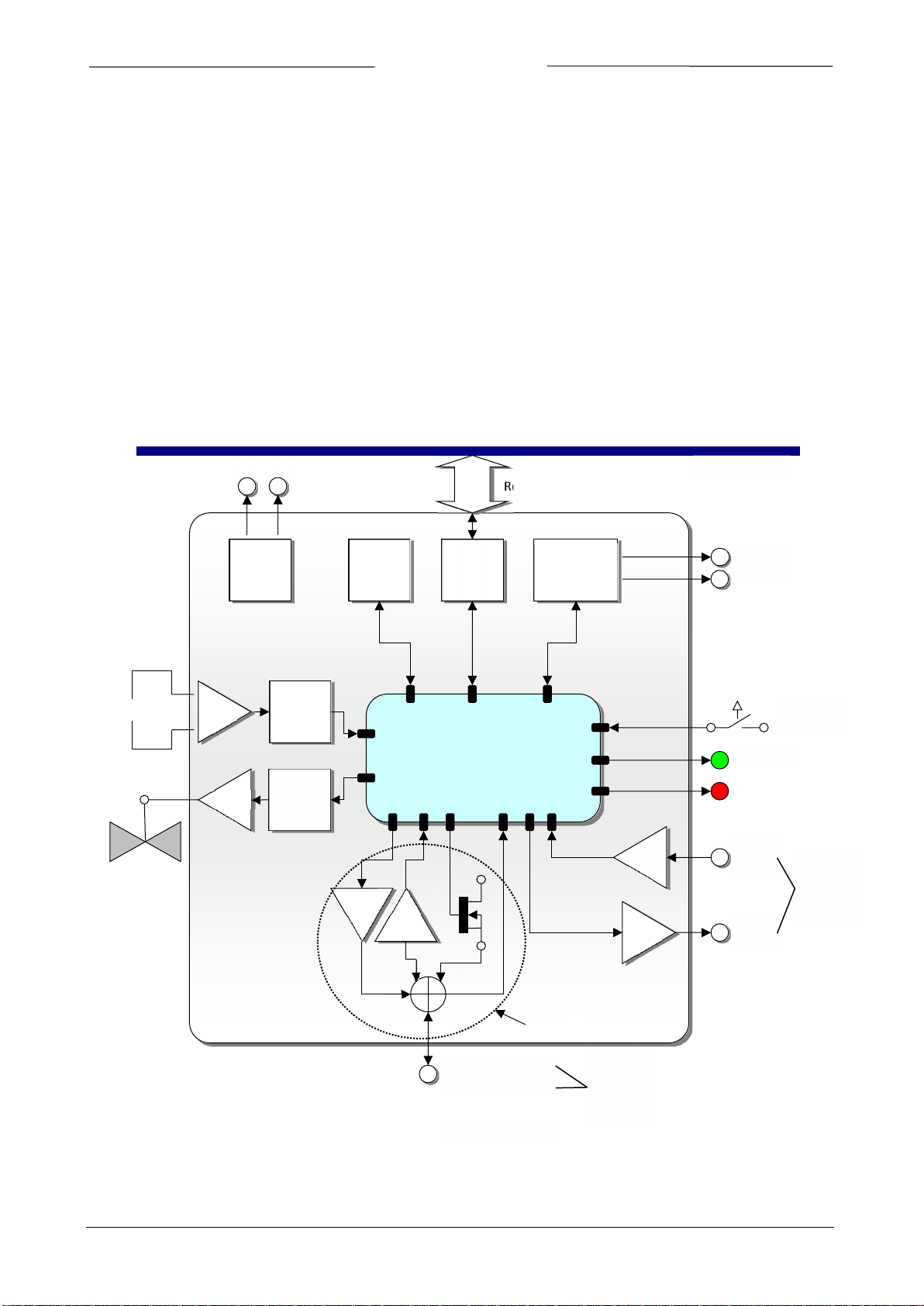
2.2 BASIC DIAGRAM
Supply
Voltage
Measure
PID
controller
Data
Memory
FIELD BUS
Interface
Digital Signal
Processing
RS485
Interface
0…10V
0…20mA
Page 7 Operational instructions for digital multibus instruments 9.17.023
0…10V
0…20mA

BRONKHORST®
Digital instruments can be operated by means of:
1. Analog interface. (0...5Vdc/0...10Vdc/0...20mA/4...20mA)
2. RS232 interface (connected to COM-port by means of special cable (Default speed 38400 Baud)
3. FLOW-BUS
4. PROFIBUS-DP
5. DeviceNet
6. Modbus
7. EtherCAT
Option 1 and 2 are always present on Multibus instruments. Option 3, 4, 5 and 6 are optional. Operation via analog
interface, RS232 interface and an optional field bus can be performed at the same time. A special parameter called
“control mode” indicates to which setpoint the controller should listen: analog or digital (via field bus or RS232). The
RS232 interface behaves like a FLOW-BUS interface. When using more digital interfaces at the same time, reading can
be done simultaneously without problems. When changing a parameter value, the last value send by an interface will
be valid.
Also the micro push-button switch and the LED’s on top of the instrument can be used for manual operation of some
options.
• The green LED will indicate in what mode the instrument is active.
• The red LED will indicate info / error / warning situations.
Page 8 Operational instructions for digital multibus instruments 9.17.023

BRONKHORST®
ADC
Bridge potmeter
ADC scaling
3
Bridge current
Exponential
filter
4
Lookup table
linearization
Polynomial
linearization
Differentiator
5
6 7 8
Differentiator
(MBC-II only)
1
Setpoint
0
Display filter
fmeasure
Measure
PID
controller
2
VALVE
SENSOR
FLOW
MEASURE
CONTROL
Monitor
Valve Out
MBC3
MBC-II
2.3 MEASURE AND CONTROL FUNCTIONAL BLOCK DIAGRAM
The main part of a digital instrument is the measuring stage. The base is a highly accurate Analog to Digital converter.
The measuring signal is than processed trough a couple of stages as shown below. In general the path is: ADC scaling,
filtering, linearization (look-up or polynomial), Differentiation (gas flow sensors only), display filtering. In case of a
control system this signal is used to control a valve. The control loop consists of an enhanced PID controller (See the
chapter “Control parameters”).
Digital mass-flow measure / controller functional block diagram
converter
smoothing
filter
Page 9 Operational instructions for digital multibus instruments 9.17.023

BRONKHORST®
n
n
XaXaXaXaay ⋅++⋅+⋅+⋅+= .....
3
3
2
210
32
XdXcXbaY ⋅+⋅+⋅+=
index X Y
x0 y
0
x1 y
1
x2 y
2
x3 y
3
…
… n xn y
n
2.4 CALIBRATION WITH MATHEMATICAL FUNCTIONS
2.4.1 General information
Depending on instrument and sensor type an instrument output signal is calculated with one of the following
mathematical methods:
• polynomial function
• look-up table (2 dimensions)
• look-up table with temperature compensation (3 dimensions)
2.4.2 Polynomial functions
By means of a few samples, a polynomial function can be obtained. After determining the polynomial function, the
original calibration points and an infinite amount of values in between, can be calculated with high accuracy. In a
system where pressure- and/or flow meters and -controllers should be readout and set with high accuracy, these
polynomial functions often are used for approximation of their transfer function.
2.4.2.1 General form of a polynomial function
In mathematics, a polynomial is an expression of finite length constructed from variables (also known as in
determinates) and constants. The general form of a polynomial function of the n-th degree is as follows:
n is a non negative integer and 'a
they can be approximated by means of a 'n
' to 'an' are polynomial constant coefficients. When you have 'n + 1' measure-points,
0
th
' degree polynomial function.
2.4.2.2 Polynomial function of sensor signal
By means of a calibration at Bronkhorst several measured calibration points will be used to obtain a polynomial
function. The form of this function of the 3
In which 'Y' is the normalized measured value (0-1) and 'X' is the value of the sensor signal. Characters 'a - d' are
polynomial parameters, which can be obtained by a mathematical program. The polynomial parameters are calculated
in such a way that the fit error between the calibration points and the polynomial function is minimized.
rd
degree is:
2.4.3 Look-up tables
It is also possible to linearize a sensor signal is using a so called look-up table. A look-up table is a table filled with
calibration points. The embedded software inside the digital instrument calculates a continuous smooth function
which fits exactly through these calibration points. Using this method it is possible to describe any monotone rising
sensor signal curve with high accuracy.
2.4.4 General form of 2-dimensional look-up tables
The general form of a 2-dimensional look-up table is as follows:
0
1
2
3
…
In which 'Y' is the real flow value, 'X' is the value of the sensor signal and ‘index’ represents the position in the look-up
table. A Bronkhorst digital instrument can store look-up tables with a maximum of 21 calibration points.
Page 10 Operational instructions for digital multibus instruments 9.17.023

BRONKHORST®
2.4.5 Using mathematical functions at a digital instrument
Digital instruments are capable of storing 8 different fluid calibrations. Parameters for these calibrations are stored
inside the instrument and can be read or changed through the field bus or the RS232 connection by means of a PCprogram or a digital Readout and Control module. Factory calibration parameters are secured and can not be changed
unless you have special rights to do this. Selection of another fluid is part of operation and therefore not secured.
Digital instruments will need at least 1 fluid set of calibration parameters for operation.
2.5 MULTI FLUID / MULTI RANGE INSTRUMENTS
2.5.1 General information
Multi Fluid / Multi Range (MFMR) instruments are calibrated for standard ranges which can easily be configured for
other fluids and ranges. This applies for both Bronkhorst and its customers. Changing fluid and range can be
performed by means of a simple computer program through the RS232 connection of an instrument. The program can
convert the primal calibration curve inside the instrument to the selected fluid and range.
MFMR instruments can be identified by the text “MFMR” on the instruments identification.
2.5.2 Differences between traditional and MFMR instruments
In traditional digital instruments the parameters capacity, density, unit type, capacity unit etc. are static parameters.
These parameters are used by, for example, read out units or PC-software to convert the measured value in
percentage of the maximum output to a real value in a certain unit.
However in MFMR instruments these parameters are dynamic.
Examples:
An instrument is configured for 2000 ml
Changing the capacity unit from ‘ml
‘2000’ to ‘2’. The 100% output is not affected.
Changing the capacity from ‘2000’ to ‘1000’ effects that the instruments full scale capacity (100% output)
changes to 1000 ml
/min. The instrument is reranged.
n
/min Air.
n
/min’ to ‘ln/min’ effects that the capacity automatically changes from
n
Page 11 Operational instructions for digital multibus instruments 9.17.023

BRONKHORST®
3 PARAMETERS AND PROPERTIES
3.1 GENERAL
Digital instruments consist of a microcontroller with several processes running simultaneously for:
• Measuring sensor value
• Reading analog input signal
• Digital signal processing
• Driving a valve
• Setting analog output signal
• Communication with the world outside
Each process needs its own specific parameters in order to function correctly. These parameter values are accessible
through the available interface(s) to influence the process behavior (for instance Control behavior or alarm settings).
These parameters can easily be controlled by end-users for more flexible use of the instruments. Bronkhorst offers
special software tooling for these purposes.
3.2 BRONKHORST SOFTWARE
FlowDDE is software which allows users to communicate with digital instruments in a standard way. It uses the RS232
interface on the instrument which is linked to a computer with a standard Bronkhorst cable. It converts the
instrument parameters to DDE commands. DDE (Dynamic Data Exchange) is a technology for communication between
multiple applications under Microsoft Windows.
FlowView and FlowPlot use FlowDDE as a server. In short:
FlowView :Windows application for the readout and/or control of 12 instruments (default), configurable up to
99 instruments.
FlowPlot :Windows application for monitoring and optimizing. (Value versus time on screen)
Page 12 Operational instructions for digital multibus instruments 9.17.023

BRONKHORST®
These programs are on the support CD or can be downloaded from:
http://www.bronkhorst.com/en/products/accessories/software_tools/
End-users are also free to use their own software using either:
FlowDDE : DDE-server for data exchange with Microsoft Windows applications
FLOWB32.DLL : Dynamic Link Library for Microsoft Windows applications
RS232 interface : Protocol for instructions with ASCII HEX or Binary telegrams
3.3 PARAMETER USE
In general each parameter has its own properties, like data-type, size, reading/writing allowance, security.
Parameters can be protected in general:
• Parameters used for operation of instruments are not secured (read / write is allowed).
(e.g..: measure, setpoint, control mode, setpoint slope, fluid number, alarm and counter)
• Parameter for settings and configuration are secured (reading is allowed/ writing is not allowed).
(e.g..: calibration settings, controller settings, identification, network/field bus settings)
Parameters for settings are secured. They can be read-out, but can not be changed without knowledge of special keyparameters and knowledge of the instrument.
Reading/changing parameter values via FlowDDE offers the user a different interface to the instrument. Besides the
server name: ‘FlowDDE’ or ‘FlowDDE2’ there is only need of:
• topic, used for channel number: ‘C(X)’ (x = channel number)
• item, used for parameter number: ‘P(Y)’ (y = parameter number)
A DDE parameter number is a unique number in a special FlowDDE instruments/parameter database and not the
same as the parameter number from the process on an instrument. Node address and process number will be
translated by FlowDDE to a channel number.
When not using FlowDDE for communication with the instrument, each parameter value needs:
• node address of instrument on FLOW-BUS
• process number on instrument
• parameter number on instrument
Page 13 Operational instructions for digital multibus instruments 9.17.023
BRONKHORST®
Document “917027--Manual RS232 interface” explains in more detail the use of RS232 communication
http://www.bronkhorst.com/en/downloads/instruction_manuals/
Data Type
Range
read/write
Secured
DDE
Proc/par
Valve output
unsigned long
0…16777215
RW Y
55
114
1
Unsigned char
1 byte integer
Unsigned int
2 bytes integer, MSB first
Unsigned long
4 bytes integer, MSB first
Float
4 bytes IEEE 32-bit single precision numbers, MSB first
Unsigned char []
array of characters (string)
Data Type
Range
read/write
Secured
DDE
Proc/par
Fluid name
unsigned char[10]
a…Z, 0…9
RW Y
25
1
17
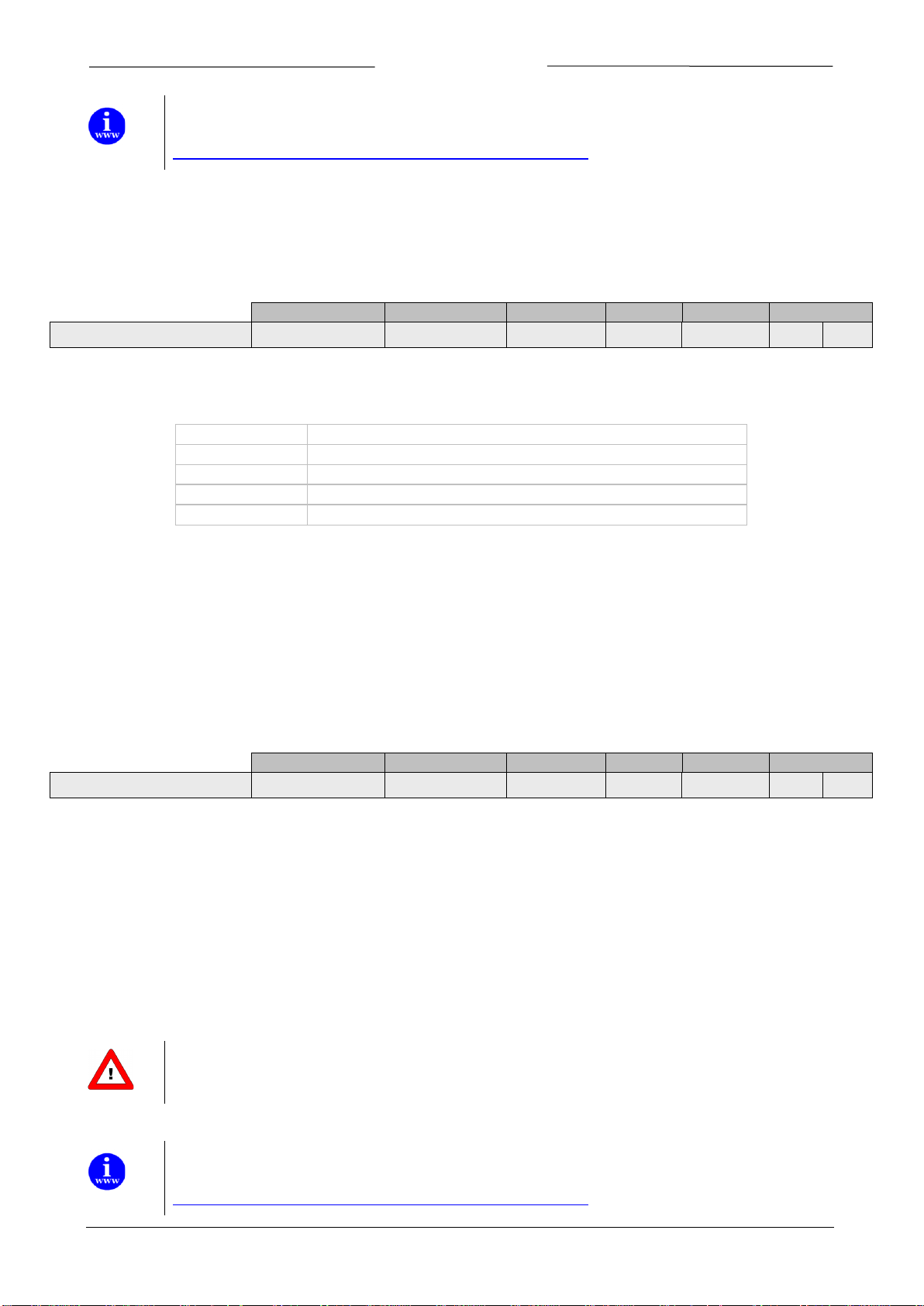
More information can be found in the manual “917030 Manual FlowPlot”
http://www.bronkhorst.com/en/downloads/instruction_manuals/
This document can be found at:
Example of a parameter and the explanation:
unsigned long = one of the data types below.
RW = R - parameter can be read, W – parameter can be written.
Secured = Y =Parameter is secured. N= Parameter not secured.
0…16777215 = Parameter range.
DDEpar. = 55 = FlowDDE parameter number
Proc. = 114 = Process number
Par. = 1 = process parameter number
Another example is:
unsigned char[10] = Data type Unsigned char[], array of characters. [10] = number of characters.
RW = R - parameter can be read, W – parameter can be written.
Secured = Y =Parameter is secured. N= Parameter not secured.
a...Z = characters which can be used in the string
0...9 = numbers which can be used in the string
DDEpar. = 25 = FlowDDE parameter number
Proc. = 1 = Process number
Par. = 17 = process parameter number
secured parameter:
To enable secured parameter, see chapter 9 SPECIAL PARAMETERS 9.2 INIT/RESET.
This document can be found at:
Page 14 Operational instructions for digital multibus instruments 9.17.023

BRONKHORST®
Page 15 Operational instructions for digital multibus instruments 9.17.023

BRONKHORST®
Data Type
Range
read/write
Secured
DDE
Proc/par
4.1 MEASURE UNIPOLAIR
unsigned int
0…41942
R
N 8 1/0
4.2 M
unsigned int
0…65535
R
N 8 1/0
4.3 F
float
-3.40282E+38 …
3.40282E+38
R
N
205
33/0
Depending on the type of instrument, measured value indicates the amount of mass flow or pressure metered by the
ng floating point notation. The
Not used
( )
capacity0%capacity0%capacity*
32000
measure
fmeasure +
−=
4 NORMAL OPERATION PARAMETERS
EASURE BIPOLAIR
MEASURE
instrument. Sensor signals at digital instruments will be digitized at the sensor bridge by means of highly accurate ADconverters. Digitized signals will be internally processed by the microcontroller usi
sensor signal will be differentiated, linearized and filtered.
At the digital output measured values can be presented in three ways:
1. For Unipolair mode the signal of 0...100% will be presented in a range of 0...32000.
For the instruments, maximum signal to be expected is 131.07 %, which is: 41942.
0 32000 41942 65535
0% 100% 131.07%
2. For Bipolair mode the signal of 0...100% will be presented in a range of 0...32000.
Maximum signal is 131.07 %, which is: 41942, minimum signal is -73.73 %, which is 41943
0 32000 41942 41943 65535
0% 100% 131.07% -73.73% -0.003%
3. Fmeasure is a different parameter as Measure. It represents the internal floating point version of the variable
Value is calculated as follows:
measure as mentioned before.
The users will read-out the measured value in the capacity and capacity unit for which the instrument has
been calibrated. These settings depend on variables: capacity, capacity unit, sensor type and capacity 0%.
Fmeasure is a read-only float on (FLOW-BUS) proc 33, par 0.
in text
Page 16 Operational instructions for digital multibus instruments 9.17.023

BRONKHORST®
4.4 S
unsigned int
0…32000
RW
N 9 1/1
4.5 FSETPOINT
float
1e-10…1e+10
RW
N
206
33/3
32000
capacity0%capacity
capacity0%fsetpoint
setpoint •
−
−
=
Reading back actual values of Fsetpoint is also possible. When a value has been send to proc1, par1
capacity and unit
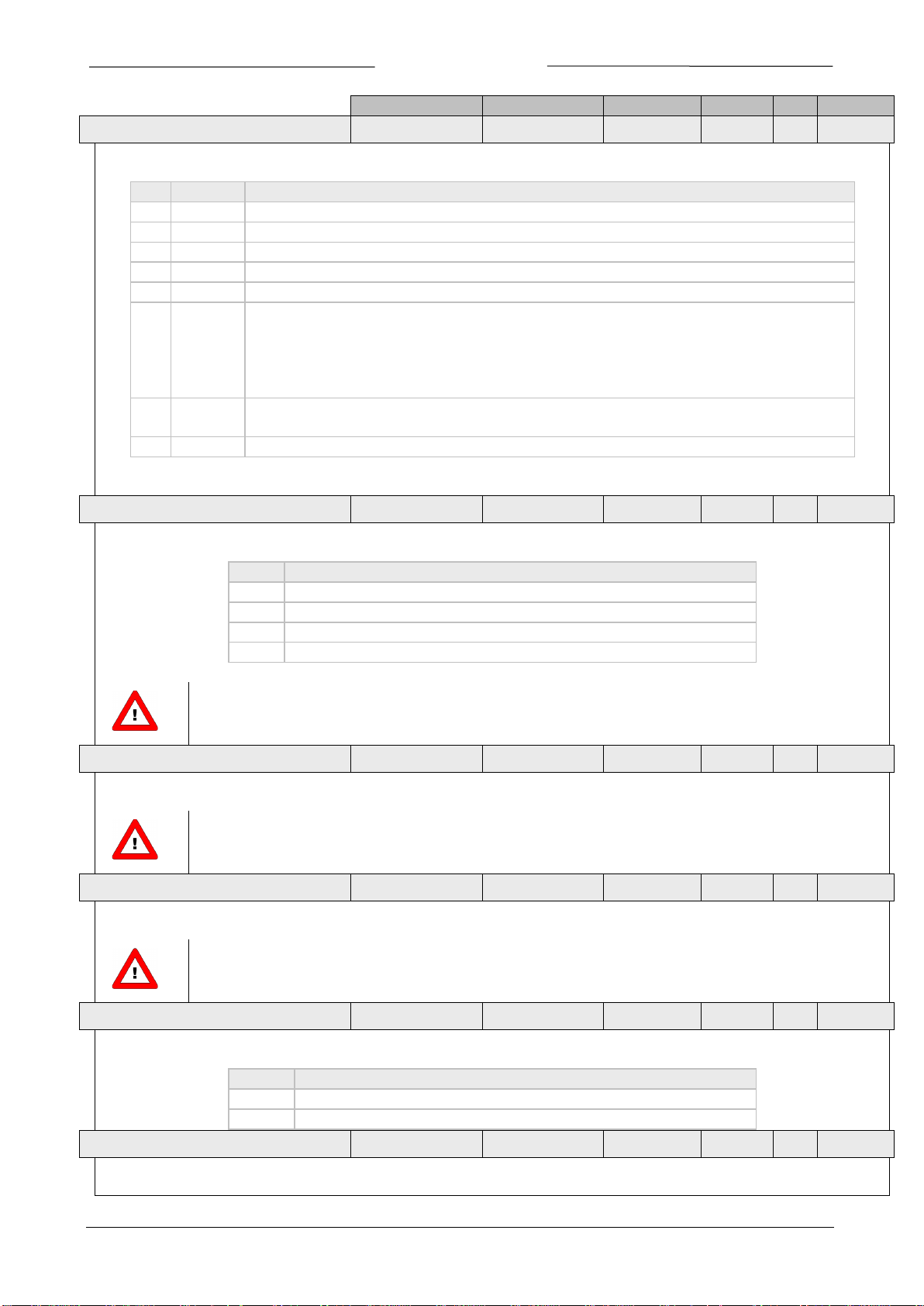
4.6 SETPOINT MONITOR MODE
unsigned char
0…255
RW Y
329
115/23
This parameter makes it possible to visualize the internal setpoint value.
Value
Description
0
Setpoint
1
Internal setpoint after Setpoint Exponential Smoothing filter
2
Internal setpoint after slope function
4.7 S
SMOOTHING FILTER
float
0…1
RW Y
73
117/3
This factor is used for filtering the setpoint before it is further processed.
filter) exp. Setpoint(1filter exp. SetpointxY
00
−•+•=
1
y
ETPOINT
Setpoint of the instrument can be operated by two parameters at the same time:
1. Setpoint is used to tell the PID controller in the instrument what the wanted amount of mass flow or pressure
is. Signals are in the same range as the measured value, only setpoint is limited between 0 and 100 %.
Setpoint can be given either via optional field bus or RS232 or via the analog interface. The parameter control
mode selects the active setpoint for the controller. See that paragraph for more detailed information.
2. With the use of parameter Fmeasure, also Fsetpoint is often needed. This parameter is R/W as variable in
FLOW-BUS proc33, par3. Fsetpoint is a float (in the capacity in which the instrument was calibrated, see also
Fmeasure). The last received setpoint by the instrument will be valid. It is not advised to use setpoint and
Fsetpoint at the same time.
Relation between setpoint and Fsetpoint is calculated as follows:
in text
(integer setpoint), then this will be converted to the float setpoint for direct reading in the right
ETPOINT EXPONENTIAL
It filters according the following formula:
Default value = 1 (off)
This filter is in the control loop so it affects the response time.
For MBC-II type of instruments this parameter affects the analog setpoint signal.
For MBC3 type of instruments this parameter affects both analog and digital setpoint signals.
Page 17 Operational instructions for digital multibus instruments 9.17.023

BRONKHORST®
4.8 S
unsigned int
0…30000
RW
N
10
1/2
Digital instruments can establish a smooth setpoint control using the setpoint slope time. The setpoint will be linear
=•
−
slope
100
oldspnewsp
610
100%
20%80%
=•
−
4.9 ANALOG INPUT
unsigned int
0…65535
R
N
11
1/3
Depending on the analog mode, 0...5Vdc / 0…10Vdc / 0...20mA / 4...20mA is converted to 0…32000.
4.10 CONTROL MODE
unsigned char
0…255
RW
N
12
1/4
For switching between different functions of a digital meter or controller several modes are available.
Mode
Instrument action
Setpoint source
Master source
Slave factor
0
BUS/RS232
Controlling
BUS/RS232
1
Analog input
Controlling
analog input
controlling as slave from other
instrument on the bus
FLOW-BUS * slave
factor /100%
slave factor
(proc33,par 1)
3
Valve close
close valve
stand-by on BUS/RS232
freezes in current position
5
Testing mode
testing enabled (factory only)
6 Tuning mode
tuning enabled (factory only)
7
Setpoint 100%
controlling on 100%
100%
8
Valve fully open
purge valve
9 Calibration mode
calibration enabled (factory only)
controlling as slave from other
instrument on analog input
Analog input * slave
factor /100%
proc33,par 1
(slave factor)
12
setpoint 0%
controlling on 0%
0%
controlling as slave from other
with signal on analog input
FLOW-BUS * analog
/100%
18
RS232
Controlling
valve stearing
(valve = setpoint)
Setpoint is redirected directly to
Valve Out with the controller idle
analog valve stearing
(valve = analog input)
Analog input is redirected directly to
Valve Out with the controller idle
22
valve safe state
See parameter Valve Safe State
IOStatus.
ETPOINT SLOPE
increased in time from old setpoint to new setpoint value. A value between 0 and 3000 seconds, with a resolution of
0.1 seconds, can be given to set the time for the integrator on the setpoint signal.
Setpoint will reach its end value after:
seconds
Sample; When slope = 10 seconds how long will it take to go from 20% to 80%?
seconds
Analog input signals (digitized) are in the same range as measured values (0...32000 = 0...100%).
This input can be used to give setpoint or slave factor, depending on the value of control mode.
2 FLOW-BUS slave
4 Controller idle
controlling is stopped / Valve Out
FLOW-BUS
10 Analog slave
13 FLOW-BUS analog slave
20
21
instrument on bus, slave factor is set
input * slave factor
analog input
FLOW-BUS *
analog input
Analog input= external input= pin 3 on DB 9 connector.
BUS = any available field bus
At power-up the control mode will be set by the jumper or dip switch setting on the PC-board of the instrument (only
for the control mode values 0, 1, 9 or 18). If the actual control mode is not equal to 0, 1, 9 or 18, it will not be
overruled by jumper or dip switch setting on the PC-board of the instrument. For more information see parameter
Page 18 Operational instructions for digital multibus instruments 9.17.023
analog input

BRONKHORST®
When operating a controller (reading measured value and sending setpoint) for proper operation it is important that
4.11 SLAVE FACTOR
float
0…500
RW
N
139
33/1
Depending on the Setpoint/control mode a slave factor can be set.
100%
factor slavealOutputsign
setpoint
(master)
(slave)
•
=
These options are available for FLOW-BUS or RS232 instruments only.
Slave factors can also be changed via RS232.
4.12 FLUID NUMBER
unsigned char
0…7
RW
N
24
1/16
Fluid number is a pointer to the set of calibration parameters. Each selectable fluid has its own set of calibration
4.13 F
unsigned char[10]
a…z / 0…9
RW Y
25
1/17
Fluid name consists of the name of the fluid of the actual selected fluid number. Up to 10 characters are available for
4.10.1 Dual interface operation
the controller gets its setpoint from the right source. Setpoints may come from different sources: analog input, field
bus interface, RS232 interface or may be overruled by close valve or open valve (purge) commands. Therefore it is
important to know what the setpoint source of the controller is. This can be set by means of parameter control mode
(DDE parameter 12).
In some cases it is possible that the setpoint may come from 2 sources at the same time. The last setpoint send will be
valid and send to the controller. This is the case in control mode = 0, when setpoints may come through any field bus
interface or RS232. However, there could be situations where control over the instrument seems impossible. This is
the case when the instrument comes into a safe-state e.g. when field bus communication is disturbed or disconnected.
The valve will be forced to a safe state automatically: closed (NC) or fully open (NO).
In case you want to get control back via RS232 operation, you have to change the control mode. When control mode
gets value 18, safe state will be overruled and sending setpoints via RS232 interface will have effect on the controller
again. ‘Control Mode’ value 18 will be lost after power off and power on of the instrument.
4.10.2 Tuning, test and calibration mode
These are special modes to prepare the instrument for either a tuning, test or calibration action. These modes are used
by Bronkhorst service personnel only and are not meant for customer use.
In master/slave or ratio control the setpoint of an instrument is related to the output signal of another instrument.
Digital instruments offer possibilities for master/slave control via the FLOW-BUS. The output value of any instrument
connected to the FLOW-BUS is automatically available to all other instruments (without extra wiring). When
master/slave control is wanted the instrument can be put in control mode 2 or 13, depending on how the slave factor
should be set (see table above). Through FLOW-BUS an instrument can be told that it should be a slave, who should be
its master (DDEpar. 158 ‘Master Node’) and what should be the slave factor to follow the master with. It is possible to
have more masters and more slaves in one system. A slave can also be a master itself for other instruments.
Output signals from master can be received via FLOW-BUS only.
Master/slave is meant here for controlling purposes and has nothing to do with master and slave behavior on field bus
networks.
parameter values. Fluid number is an unsigned char parameter (DDEpar. 24 ‘Fluid number’) in the range of 0...7, where
0 = fluid1 and 7 = fluid8. Up to 8 fluids can be stored in one instrument. Default value = 0 (fluid 1).
LUID NAME
storage of this name. This parameter is secured and read-only for normal users (it is written during calibration at the
factory). Default value is “Air”.
Page 19 Operational instructions for digital multibus instruments 9.17.023

BRONKHORST®
4.14 V
unsigned long
0…16777215
RW Y
55
114/1
This parameter is the signal coming out of the controller, going to the DAC for driving the valve. 0...16777215
4.15 T
float
-250…500
RW
N
142
33/7
In MBC3 type of instruments the temperature surrounding the sensor is shown.
4.16 A
float
-3.40282E+38 …
3.40282E+38
R
N
270
116/15
This parameter shows the Actual Density measured by the (mini) CORI-FLOW. It is not used in other instruments.
4.17 S
unsigned char
0…255
RW Y
22
1/14
Unsigned char used to select proper set of units for certain sensor, together with Counter unit (MBC-II type).
Value
Description
Controller/Sensor
0
pressure (no counting allowed)
1
liquid volume
2
liquid/gas mass
3
gas volume
4
other sensor type (no counting allowed)
128
pressure (no counting allowed)
129
liquid volume
130
liquid/gas mass
131
gas volume
132
other sensor type (no counting allowed)
4.18 C
100%
float
1e-10…1e+10
RW Y
21
13
Capacity is the maximum value (span) at 100% for direct reading in readout units. The readout unit will be determined
4.19 CAPACITY 0%
float
1e-10…1e+10
RW Y
183
33/22
This is the capacity zero point (offset) for direct reading in readout units. The readout unit will be determined by the
ALVE OUTPUT
corresponds with approximately 0...300mAdc. Maximum output voltage is the supply voltage and therefore in practice
300 mAdc may not be reached.
EMPERATURE
For (mini) CORI-FLOW type of instruments this parameter shows the temperature of the tubes.
It is not used in other instruments.
CTUAL DENSITY
ENSOR TYPE
Default setting is 3.
APACITY
by the capacity unit index / string. For each fluid (number) capacity will be stored separately.
capacity unit index / string. For each fluid (number) capacity will be stored separately.
Controller
Sensor
Page 20 Operational instructions for digital multibus instruments 9.17.023

BRONKHORST®
4.20 C
unsigned char
0…4
RW Y
23
1/15
capacity unit index (limited unit table)
0 1 2 3 4 5 6 7 8
9
0
bar
mbar
psi
kPa
cmH2O
cmHg
atm
kgf/cm2
1
l/min
ml/h
ml/min
l/h
mm3/s
cm3/min
2
kg/h
kg/min
kg/s
g/h
g/min
g/s
mg/h
mg/min
mg/s
3
ln/min
mln/h
mln/min
ln/h
m3n/h
mls/min
mls/h
ls/min
ls/h
m3s/h
4
usrtype
usrtype
usrtype
APACITY UNIT INDEX
This parameter gives access to the limited unit table which is available for MBC-II and MBC3 type of
instruments.
Capacity unit index is a pointer to select an actual readout unit (see list below). For FLOW-BUS instruments all capacity
units are available for direct reading. Other field busses (eg. DeviceNet) are limited in options for direct reading
facilities.
Sensor
Type
name description
sensor type Indicator for type of sensor in instrument in relation with a list of units for direct reading
capacity unit index Points to the capacity unit for direct reading in list of available units
Example:
If you want to readout your instrument in ln/min, then make sure parameter “sensor type” is set to value 3 and
parameter “capacity unit index” is set to value 0. By means of parameter “capacity unit” the unit string can be readback as a 7 character string.
Page 21 Operational instructions for digital multibus instruments 9.17.023

BRONKHORST®
4.21 C
unsigned char[7]
see table
RW Y/N
129
1/31
For MBC3 type of instruments this parameter can be read and written.
table below in capacity unit.
Extended unit table
Pressure
A
mbar(a)
bar(a)
gf/cm2a
kgf/cma
psi(a)
torr(a)
Pa(a)
hPa(a)
kPa(a)
MPa(a)
atm(a)
mmH2O(a)
cmH2Oa
mH2O(a)
"H2O(a)
ftH2Oa
mmHg(a)
cmHg(a)
"Hg(a)
Pressure
G
mbar(g)
bar(g)
gf/cm2g
kgf/cmg
psi(g)
torr(g)
Pa(g)
hPa(g)
kPa(g)
MPa(g)
atm(g)
mmH2Og
cmH2Og
mH2O(g)
"H2O(g)
ftH2Og
mmHg(g)
cmHg(g)
"Hg(g)
D
mbar(d)
bar(d)
gf/cm2d
kgf/cmd
psi(d)
torr(d)
Pa(d)
hPa(d)
kPa(d)
MPa(d)
atm(d)
mmH2Od
cmH2Od
mH2O(d)
"H2O(d)
ftH2Od
mmHg(d)
cmHg(d)
"Hg(d)
ug/h
ug/min
ug/s
mg/h
mg/min
mg/s
g/h
g/min
g/s
kg/h
kg/min
kg/s
ul/h
ul/min
ul/s
ml/h
ml/min
ml/s
l/h
l/min
l/s
cc/h
cc/min
cc/s
mm3/h
mm3/m
mm3/s
cm3/h
cm3/min
cm3/s
m3/h
m3/min
m3/s
cfh
cfm
cfs
Normal
Flow
uln/h
uln/min
uln/s
mln/h
mln/min
mln/s
ln/h
ln/min
ln/s
ccn/h
ccn/min
ccn/s
mm3n/h
mm3n/m
mm3n/s
cm3n/h
cm3n/m
cm3n/s
m3n/h
m3n/min
m3n/s
scfh
scfm
scfs
sccm
slm
Standard
Flow
uls/h
uls/min
uls/s
mls/h
mls/min
mls/s
ls/h
ls/min
ls/s
ccs/h
ccs/min
ccs/s
mm3s/h
mm3s/m
mm3s/s
cm3s/h
cm3s/m
cm3s/s
m3s/h
m3s/min
m3s/s
APACITY UNIT
This parameter gives access to the extended unit table which is available for MBC3 type of instruments
only.
For MBC-II type of instruments this parameter can only be read.
Only if sensor type = 4 (other sensor type) this parameter can be written
The easiest way to change a unit in the MBC3 type of instrument is to fill in the unit needed from the
The “Capacity unit” displays the unit name set by “Capacity unit index”. A valid “Capacity unit”(for example ln/min) can
also be entered here which changes the “Capacity unit index”. In MBC3 type of instruments the parameter is not
secured.
Pressure
Mass Flow
(Custom)
Volume
Flow
Volume
Volume
Due to compatibility the maximum string length is limited to 7 characters. Therefore unit names may
be truncated. For instance mm3n/m means mm3n/min.
Page 22 Operational instructions for digital multibus instruments 9.17.023

BRONKHORST®
Data Type
Range
read/write
Secured
DDE
Proc/par
5.1 PID-KP
float
0…1E+10
RW Y
167
114/21
PID controller response, proportional action, multiplication factor.
5.2 PID-TI
float
0…1E+10
RW Y
168
114/22
PID controller response, integration action in seconds.
5.3 PID-TD
float
0…1E+10
RW Y
169
114/23
PID controller response, differentiation action in seconds.
5.4 C
(Kspeed)
float
0…3.40282E+38
RW Y
254
114/30
This parameter is the controller speed factor. PID-Kp is multiplied by this factor.
5.5 OPEN FROM ZERO RESPONSE
unsigned char
0…255
RW Y
165
114/18
,
Zero) from Open(128
1.05*response oldresponse New
−
=
S
+
Sensor
Control Valve
Flow
Setpoint
P
I
D
+ + +
5 CONTROL PARAMETERS
The controlling algorithm for the valve handled by the micro-controller consists of several parameters which can be
set via the BUS/RS232. Although many parameters could be accessed via BUS/RS232, Bronkhorst advises not to
change these parameters because during manufacturing they have got optimal values for their purposes. Changing of
controller settings should be performed by or under supervision from trained service personnel only.
The picture below shows the basic controller diagram of the digital instrument. It consists of a standard PID controller
with a number of add-ons.
K
open
K
speed
Basically, when a faster or slower controller response is needed, only the controller speed (Kspeed) or PID-Kp has to
be changed.
Kp
K
normal
K
stable
ONTROLLER SPEED
Controller response when starting-up from 0% (K
Value 128 is default and means: no correction.
Otherwise controller speed will be adjusted as follows:
Kp multiplication factor when valve opens).
open
Page 23 Operational instructions for digital multibus instruments 9.17.023

5.6 N
ORMAL STEP RESPONSE
unsigned char
0…255
RW Y
72
114/5
,
Step) Normal(128
1.05*response oldresponse New
−
=
5.7 S
unsigned char
0…255
RW Y
141
114/17
,
response) Stable(128
1.05*response oldresponse New
−
=
5.8 S
float
0…1E+10
RW Y
51
1/12
Sensor time constant (upwards).
5.9 S
DOWN
float
0…1E+10
RW Y
50
1/11
Sensor time constant (downwards).
5.10 S
SMOOTHING FILTER
float
0…1
RW Y
74
117/4
This factor is used for filtering the signal coming from the sensor circuitry before it is further processed.
filter) exp. Sensor(1filter exp. SensorxY
00
−•+•=
1
y
Response
Factor setting
Slow
0.05
Normal
0.1
Fast
0.2
Very fast
0.5...1.0 (not advised)
Controller response during normal control (K
normal
TABLE RESPONSE
Controller response when controller is stable (K
ENSOR DIFFERENTIATOR UP
ENSOR DIFFERENTIATOR
BRONKHORST®
Kp multiplication factor at setpoint step)
Kp multiplication factor within band of 2%)
stable
ENSOR EXPONENTIAL
It filters according the following formula:
For EL-FLOW types of instruments it will be the “slow” (not differentiated), non-linearized sensor signal. Only in case of a
noisy sensor signal this value will have another value than 1.0. Advise: do not give a value much lower than 0.8, otherwise it
would slow down sensor response too much. Best setting: 1.0.
For (mini) CORI-FLOW instruments it will influence the amount of averaging of the “bare” values. The smaller this value
gets, the slower a (mini) CORI-FLOW instrument will get a sensor signal, but less noise will be on the signal.
This filter is in the control loop so it affects the response time.
Page 24 Operational instructions for digital multibus instruments 9.17.023

BRONKHORST®
5.11 V
Unsigned char
0…255
RW
N
301
115/31
The controller module will go to a safe state in the following situations:
Decimal value
Description
0
Deactivate valve (0mA)
1
Activate valve (max current)
2
Close valve
3
Open valve
4
Hold valve in current position
5
Hold valve at safe value
If Initreset = 73 the fail safe state mode will always be “hold valve in current position”
“Hold valve at safe value” can only be used with DeviceNet instruments.
ALVE SAFE STATE
• If bus communication is lost and control mode = 0 (DeviceNet and PROFIBUS only)
• if initreset = 73
• if control mode = 22 (new safe state control mode)
In fail safe state the green LED will be blinking (0.1 s on, 2 sec off).
The valve will react to the fail safe state according to the table below.
Page 25 Operational instructions for digital multibus instruments 9.17.023

BRONKHORST®
Alarm
mode 0..3
Alarm delay
time 0..255
Alarm new
Alarm setpoint
mode 0,1
Reset alarm
enable 0..15
80%
15%
Minimum alarm
limit 4800 = 15%
Maximum alarm
limit 25600 = 80%
Measure
0…32000
+3%
-4%
Minimum alarm limit
= 1280 = 4%
Maximum alarm
limit = 960 = 3%
Measure
0…32000
Setpoint
0…32000
Off
Power-up
Max
Min
Min
Max
Hardware
alarm
Master/
Slave alarm
Batch
counter limit
Warning
message
Error
message
+
Old Setpoint
Setpoint
Automatic
External
Keyboard/
Micro-switch
After Reset
alarm will still
during “Alarm
Reset
alarm
Setpoint
0…32000
bit[0]
bit[1]
bit[4]
bit[6]
bit[7]
Reset
Response
alarm
Min/Max
alarm
Alarm
info 0..7
Min. Alarm
Max. Alarm
Power-up
Response
bit[2]
bit[3]
bit[5]
bit[5]
bit[0]
bit[1]
bit[2]
bit[3]
Min/max
Response
Alarm must
External
Parameter
6 ALARM / STATUS PARAMETERS
6.1 GENERAL
Bronkhorst digital instruments have a build in alarm function. It is used to indicate several types of alarms:
• System errors
• System warnings
• Min/max alarms
• Response alarms
• Batch alarm
• Master slave alarms
The alarm can be read out using parameter alarm info. After an alarm a setpoint change can be set. This means the
setpoint will go to the set value after an alarm occurs. A delay can be set to prevent reaction to glitches in
measurement or power. How an alarm can be reset is controlled by the parameter “reset alarm enable”. It can bitwise be set to automatic, reset, external or keyboard/micro-switch. After the reset the alarm stays present during the
alarm delay time. In the functional schematic below the basic alarm function is explained.
6.2 FUNCTIONAL ALARM SCHEMATIC
be present
during
“Alarm
delay time“
before
activation
be present
delay time“
&
Page 26 Operational instructions for digital multibus instruments 9.17.023
setpoint 0…32000
BRONKHORST®
Data Type
Range
read/write
Secured
DDE
Proc/par
6.3 A
unsigned char
0…255
R
N
28
1/20
This parameter contains 8 bits with status information about some (alarm) events in the instrument.
Bit
low (0)
High (1)
0
no error
An error occurred: Alarm register 2 contains an error
1
no error
A warning occurred: Alarm register 1 contains a warning
2
no error
Minimum alarm: Sensor signal < minimum limit
3
no error
Maximum alarm: Sensor signal > maximum limit
4
no error
Batch counter: Reached its limit
5
no error
This bit only: Power-up alarm (probably power dip occurred)
(bit 2 or bit 3 indicate if difference is positive or negative)
6
no error
Master/slave alarm: master output signal not received or slave factor out of
limits (> 100%)
7
no error
Hardware alarm: check hardware
6.4 A
unsigned char
0…3
RW
N
118
97/3
Available alarm modes for device:
Bit
Description
0
Off 1 alarm on absolute limits
2
alarm on limits related to setpoint (response alarm)
3
alarm when instrument powers-up (e.g. after power-down)
6.5 A
unsigned int
0…32000
RW
N
116
97/1
Maximum limit for sensor signal to trigger alarm situation (after delay time).
6.6 A
unsigned int
0…32000
RW
N
117
97/2
Minimum limit for sensor signal to trigger alarm situation (after delay time).
6.7 A
unsigned char
0…1
RW
N
120
97/5
Available alarm setpoint modes for device:
Value
Description
0
no setpoint change at alarm
1
new/safe setpoint at alarm enabled (set at alarm new setpoint)
6.8 ALARM NEW SETPOINT
unsigned int
0…32000
RW
N
121
97/6
New/safe setpoint during alarm situation until reset.
LARM INFO
Together wit bit 2 or bit 3: Response alarm message
(setpoint-measure too much difference)
LARM MODE
Not all modes are available for all field busses. E.g. for DeviceNet only mode 0 and 1 are available.
LARM MAXIMUM LIMIT
Minimum limit ≤ Maximum limit ≤ 100%
LARM MINIMUM LIMIT
0% ≤ Minimum limit ≤ Maximum limit
LARM SETPOINT MODE
Page 27 Operational instructions for digital multibus instruments 9.17.023
BRONKHORST®
6.9 A
unsigned char
0…255
RW
N
182
97/7
Time in seconds alarm action will be delayed when alarm limit has been exceeded.
6.10 RESET ALARM ENABLE
unsigned char
0…15
RW
N
156
97/9
Available alarm reset options:
Automatic
Reset
par 114
External*
Keyboard/
micro-switch
Value
bit[3]
bit[2]
bit[1]
bit[0]
0 0 0 0 0 1 0 0 0
1 2 0 0 1
0 3 0 0 1
1 4 0 1 0
0 5 0 1 0
1 6 0 1 1
0
7 0 1 1 1 8 1 0 0
0 9 1 0 0
1
10 1 0 1 0
11 1 0 1 1
12 1 1 0 0
13 1 1 0 1
14 1 1 1 0
15 1 1 1 1
6.11 STATUS
unsigned char
0…255
R
N
This parameter is a special byte for monitoring PROFIBUS communication. It contains 8 bits with information about certain
Bit
Low (0)
High (1)
0
no error in communication with channel
error in communication
1
no parameter process error
a parameter process error has occurred
2
no parameter error
a parameter error has occurred
3
no parameter type error
a parameter type error has occurred
4
no parameter value error
a parameter R value error has occurred
5
no error
a parameter process claim or command error has occurred
6
Reserved
7
Reserved
6.12 S
unsigned char
0…255
R
N
Index pointing to the first byte in the PROFIBUS output data for which the above status bits applies (only for PROFIBUS).
LARM DELAY TIME
Also time in second’s automatic reset will be delayed when sensor signal reaches safe level again.
*External is not used in MBC-II and MBC3 type instruments.
(alarm) events.
This parameter cannot be read via FlowDDE.
TATUS OUT POSITION
This parameter cannot be read via FlowDDE.
Page 28 Operational instructions for digital multibus instruments 9.17.023

BRONKHORST®
Send following parameter values:
Action
Parameter
Value
Maximum alarm on 90%.
send to
Alarm maximum limit
28800
Minimum alarm on 10%.
send to
Alarm minimum limit
3200
No new setpoint wanted at crossing alarm limit.
send to
Alarm setpoint mode
0
Reset alarm enable *
12
Delay on action at output should be 10 seconds.
send to
Alarm delay time
10
Reset should be automatically, when signal
comes into safe area again or via FLOW-BUS.
send to
Alarm mode
1
Send following parameter values:
Action
Parameter
Value
Maximum alarm limit on setpoint + 3%.
send to
Alarm maximum limit
960
Minimum alarm limit on setpoint – 0.9%.
send to
Alarm minimum limit
288
send to
Alarm setpoint mode
1
send to
Alarm new setpoint
0 send to
Reset alarm enable *
5
Delay on action at output should be 2 minutes.
send to
Alarm delay time
120
Reset via keyboard or BUS/RS232.
send to
Alarm mode
2
6.13 USING AN ALARM (EXAMPLES)
Using the alarms will take three steps:
1. Preparing the instrument (setting correct values for mode, limits etc.)
2. Monitoring the alarm info byte (gives info which alarm has occurred)
3. Resetting the alarm (will re-initialize the alarm and set output to normal values again)
6.13.1 Using maximum and minimum alarm
This alarm will check if the measured signal crosses the maximum or minimum limit set by the user.
Example
*) Default all reset inputs are enabled, so this command isn’t really necessary
Now the alarm will be active.
Alarm status can be monitored by means of parameter alarm info.
Resetting the alarm will need the following command reset = 0 and then reset = 2.
To inactivate the alarm, put it in alarm mode “off”. This will also reset your outputs.
This can be done sending command: alarm mode = 0.
6.13.2 Using instrument with response alarm
This alarm will check if the measured value will come within an area limited by maximum limit and minimum limit,
related to the setpoint, within a certain delay-time.
Example
Setpoint wanted at crossing alarm limit = 0%.
*) Default all reset inputs are enabled, so this command isn’t really necessary
Now the alarm will be active.
Alarm status can be monitored by means of parameter alarm info.
Resetting the alarm will need the following command reset = 0 and then reset = 2.
To inactivate the alarm, put it in alarm mode “off”. This will also reset your outputs.
This can be done sending command: alarm mode = 0.
Page 29 Operational instructions for digital multibus instruments 9.17.023

7 COUNTER PARAMETERS
Data Type
Range
read/write
Secured
DDE
Proc/par
7.1 C
float
0…10000000
RW
N
122
104/1
Actual counter value in units selected at Counter unit. Value is a float in IEEE-754 32-bits single precision notation.
7.2 COUNTER MODE
Unsigned char
0…2
RW
N
130
104/8
Available counter modes for device:
Value
Description
0
Off 1 counting upwards continuously
2
counting up to limit (batch counter)
7.3 C
Unsigned char
0…1
RW
N
126
104/5
Setpoint change enable during counter limit/batch situation (until reset). Default = 0.
Value
Description
0
no setpoint change at batch limit allowed
1
setpoint change at batch limit allowed
Counter
mode 0..2
Counter new
setpoint 0…32000
Counter setpoint
Reset counter
enable 0..15
time
Measure
0…32000
time
Counter limit
Measure
0…32000
Off
Old Setpoint
Setpoint
Automatic
External
Keyboard/
Micro-switch
Reset
Reset
UP to limit
UP
bit[0]
bit[1]
bit[2]
bit[3]
Up
Up to limit
Parameter
Counter
value
Counter
value
BRONKHORST®
mode 0,1
counter
OUNTER VALUE
Default value = 0.
OUNTER SETPOINT MODE
&
Page 30 Operational instructions for digital multibus instruments 9.17.023

BRONKHORST®
7.4 C
Unsigned int
0…32000
RW
N
127
104/6
New/safe setpoint at counter limit/batch situation (until reset). See measure for range.
7.5 COUNTER LIMIT
float
0…9999999
RW
N
124
104/3
Counter limit/batch in units selected at Counter unit. Value is a float in IEEE-754 32-bits single precision notation. Default
7.6 COUNTER UNIT INDEX
Unsigned char
0…13
RW
N
123
104/2
counter unit index table (limited unit table)
0 1 2 3 4 5 6 7 8 9 10
11
12
13
1 l mm3
ml
cm3
ul
m3 2 g
mg
ug
kg
3
ln
mm3n
mln
cm3n
uln
dm3n
m3n
uls
mm3s
mls
cm3s
ls
dm3s
m3s
nr
Sensor type
0
pressure (no counting allowed)
1
liquid volume
2
liquid/gas mass
3
gas volume
4
other sensor type (no counting allowed)
OUNTER NEW SETPOINT
Normally this value is set to 0%.
setting is 0 ln.
This parameter gives access to the limited unit table which is available for MBC-II and MBC3 type of
instruments.
Counter unit index is a pointer to select an actual readout unit (see list below).
Sensor
Type
Sensor type number explanation:
Page 31 Operational instructions for digital multibus instruments 9.17.023

BRONKHORST®
7.7 C
unsigned char[4]
string
RW
N
128
104/7
For MBC3 type of instruments this parameter can be read and written.
table below.
Extended counter unit table
Mass
ug
mg g kg
Custom volume
ul
ml l mm3
cm3
dm3
m3
Normal volume
uln
mln
ln
mm3n
cm3n
dm3n
m3n
Standard volume
uls
mls
ls
mm3s
cm3s
dm3s
m3s
7.8 RESET COUNTER ENABLE
Unsigned char
0…15
RW
N
157
104/9
Available counter reset options:
Automatic
Reset
par 114
External*
Keyboard/
micro-switch
Value
bit[3]
bit[2]
bit[1]
bit[0]
0 0 0 0 0
1 0 0 0 1 2 0 0 1
0
3 0 0 1 1 4 0 1 0
0 5 0 1 0
1
6 0 1 1 0 7 0 1 1
1
8 1 0 0 0 9 1 0 0
1
10 1 0 1 0
11 1 0 1 1
12 1 1 0 0
13 1 1 0 1
14 1 1 1 0
15 1 1 1 1
OUNTER UNIT
This parameter gives access to the extended counter unit table which is available for MBC3 type of
instruments only.
This parameter can only be read for MBC-II type of instruments.
The easiest way to change a unit in the MBC3 type of instrument is to fill in the unit needed from the
The “Counter unit” displays the unit name set by “Counter unit index”. A valid “Counter unit”(for example ln) can also be
entered here which changes the “Counter unit index”.
In MBC3 type of instruments the parameter is not secured.
*External is not used in MBC-II and MBC3 type instruments.
Page 32 Operational instructions for digital multibus instruments 9.17.023

BRONKHORST®
7.9 C
float
0…3.40282E+38
RW
N
274
104/10
7.10 C
float
0…3.40282E+38
RW
N
275
104/11
Send following parameter values:
Action
Parameter
Value
The batch is reached at 1000 ln.
send to
Counter limit
1000.0
New setpoint when reaching the limit to 0%
(valve should be closed).
send to
Counter setpoint mode
1
send to
Counter new setpoint
0
Reset should be enabled via BUS/RS232 or by
means of keyboard/micro-switch.
send to
Reset counter enable *
5
Set counter to batch counter.
send to
Counter mode
2
OUNTER CONTROLLER
OVERRUN CORRECTION
CORI-FLOW instruments only.
OUNTER CONTROLLER GAIN
CORI-FLOW instruments only.
7.11 USING A COUNTER (EXAMPLE)
Using the counter will take three steps:
1. Preparing the instrument (setting correct values for mode, limit etc.)
2. Monitoring the alarm info byte (gives info which alarm has occurred)
3. Resetting the counter (will re-initialize the counter and set output to normal values again)
7.11.1 Using a batch counter
The measured signal will be integrated in time and there will be a check on a certain limit set by the user.
Example
*) Default all reset inputs are enabled, so this command isn’t really necessary
Now the counter will be active.
Alarm / Counter status can be monitored by means of parameter alarm info.
Resetting the counter will need the following command reset = 0 and then reset = 3.
To inactivate the counter, put it in counter mode “off”. This will also reset your outputs.
This can be done sending command: counter mode = 0.
Page 33 Operational instructions for digital multibus instruments 9.17.023

BRONKHORST®
Data Type
Range
read/write
Secured
DDE
Proc/par
8.1 SERIAL NUMBER
unsigned char[20]
String
RW Y
92
113/3
This parameter consists of a maximum 20-byte string with instrument serial number for identification.
8.2 BHTM
unsigned char[]*
String
RW Y
91
113/2
Bronkhorst instrument model number information string.
8.3 FIRMWARE VERSION
unsigned char[6]
String
R Y
105
113/5
Revision number of firmware. E.g. “V1.10b”
8.4 USERTAG
unsigned char[16]
String
RW Y
115
113/6
User definable alias string. Maximum 16 characters allow the user to give the instrument his own tag name. It is
8.5 CUSTOMER MODEL
unsigned char[16]
String
RW Y
93
113/4
Digital instrument customer model information string.
8 IDENTIFICATION PARAMETERS
Example: “M11202123A”
ODEL NUMBER
*For MBC-II type length = 23 bytes, for MBC3 type the length = 27 bytes
advised here to limit the name up to 7 characters when using E-7000 readout and control modules. These modules can
display the tag of an instrument only up to 7 characters. E.g.: “Room1s6”
This string can be used by Bronkhorst to add extra information to the model number information.
Page 34 Operational instructions for digital multibus instruments 9.17.023

BRONKHORST®
8.6 I
unsigned char
0…255
RW Y
175
113/12
Bronkhorst (digital) device/instrument identification number (pointer).
Value
Type
Description
0
UFO?
Unidentified FLOW-BUS Object
1
RS232
RS232/FLOW-BUS interface
2
PC/ISA
PC(ISA) interface
3
ADDA4
ADDA4 (4 channels)
4
R/C
R/C-module, 32 channels
5
T/A
T/A-module
6
ADDA1
1 channel ADDA converter module
7
DMFC
Digital Mass Flow Controller
8
DMFM
Digital Mass Flow Meter
9
DEPC
Digital Electronic Pressure Controller
10
DEPM
Digital Electronic Pressure Meter
11
ACT
Single Actuator
12
DLFC
Digital Liquid Flow Controller
13
DLFM
Digital Liquid Flow Meter
14
DSCM-A
Digital Single Channel Module for Analog instruments
15
DSCM-D
Digital Single Channel Module for Digital instruments
16
FRM
FLOW-BUS Rotor Meter (calibration-instrument)
17
FTM
FLOW-BUS Turbine Meter (calibration-instrument)
18
FPP
FLOW-BUS Piston Prover/tube (calibration-instrument)
19
F/A
special version of T/A-module
20
DSCM-E
Digital Single Channel Module for Evaporator
21
DSCM-C
Digital Single Channel Module for Calibrators
22
DDCM-A
Digital Dual Channel Module for Analog instruments
23
DMCM-D
Digital Multi Channel Module for Digital instruments
24
PRODPS
PROFIBUS DP / FLOW-BUS -slave interface
25
FCM
FLOW-BUS Coriolis meter
26
FBI
FLOW-BUS Balance Interface
27
CORIFC
(mini) CORI-FLOW Controller
28
CORIFM
(mini) CORI-FLOW Meter
29
FICC
FLOW-BUS Interface Climate Control
30
IFI
Instrument FLOW-BUS interface
31
KFI
Keithley FLOW-BUS Interface
32
FSI
FLOW-BUS Switch Interface
33
MSCI
Multi Sensor/Controller Interface
34
APP-D
Active Piston Prover (calibration-instrument)
35
LFI
Leak tester FLOW-BUS Interface
8.7 D
unsigned char[6]
String
R
N
90
113/1
Device type information string: String value in max. 6 characters of descriptions in table above.
DENTIFICATION NUMBER
See list below:
EVICE TYPE
Page 35 Operational instructions for digital multibus instruments 9.17.023

9 SPECIAL PARAMETERS
Data Type
Range
read/write
Secured
DDE
Proc/par
9.1 RESET
Unsigned char
0…5
W
N
114
115/8
Parameter to reset program, counter or alarms. Default value = 0.
Value
Description
0
no reset
1
reset counter value (no mode change) or common reset
2
reset alarm
3
restart batch counter
4
reset counter value (counter off)
5
reset module (soft reset)
6
reset alarm info error bit (bit 0) See ‘Alarm info’
7
reset alarm info warning bit (bit 1) See ‘Alarm info’
9.2 I
Unsigned char
0…255
RW
N 7 0/10
9.3 WINK
Unsigned char
0…9
W
N 1 0/0
Unsigned char in range ‘0’...’9’ send to this parameter lets the instrument which is addressed wink for several seconds for
9.4 IOSTATUS
Unsigned char
0…255
RW Y
86
114/11
The parameter IOStatus (parameter 86) is used to read and enable / disable the physical jumpers and micro switch.
Bit
Decimal Value
Explanation
Read/Write
Default 0 1
true = read ‘special purpose’ jumper
RW
1 1 2
not used 1 2 4
true = read ‘analog mode jumper’
RW
1 3 8
true = read ‘micro switch’
RW
1 4 16
special purpose jumper off/on
R(W)
(0) 5 32
internal initialization jumper off/on
R(W)
(0)
6
64
analog mode jumper off/on
R(W)
(0) 7 128
micro switch off/on
R
For bits 4,5,6 the jumper can be a real jumper on the pc board or a virtual jumper (MBC3 type).
In case of a virtual jumper the bits 4,5,6 are set by firmware (MBC3 type).
To make sure the parameter is accepted send a 0 first.
BRONKHORST®
NIT / RESET
( key parameter)
Init and reset security key command for network/parameter settings.
Write 64 to enable changing of secured parameters. Write 82 or 0 to disable changing of secured parameters.
When an instrument powers-up this value will be reset to 82 automatically.
tracing the physical location. Type of winking depends on instrument. This will be either with red and green LED turn-byturn or with special characters on a display. Default setting = 0.
In case of a real jumper the bits 4,5,6 are read from the pc board.
Page 36 Operational instructions for digital multibus instruments 9.17.023

BRONKHORST®
Flatconductor
cable
main PC board
fieldbus
interface
123
4
S1S2S3S4
on
off
Switch
Jumper
IOstatus
bit
When placed
(on)
When not placed
(off)
Remarks
S2
J1
5
Default settings from
Settings loaded from
If S2 is placed all settings are
calibration.
S3
J2
6
Analog input used as
Digital (bus) input used
Setting depends on how instrument was
up however, controller
will read jumper first for setpoint source.
S4
J3
4
reserved
-
J4
reserved
Not always present
S1
J5
Normal RS232
communication
Instrument in FLASH
mode
(J4)
J5
J1
J3
J2
J5
CORI-FLOW
J2
J1
J3
MBC-II
J1
J2
J3
J5
L30
digital
With Jumper
9.4.1 Examples of using parameter IOstatus
• When the analog jumper is set the value of parameter 86 will read: 1+2+4+8+64 = 79
• To disable the micro switch bit 3 must be false, value of parameter 86 must be set to.: 1+2+4 = 7
• To disable the analog jumper bit 2 must be false, value of parameter 86 must be set to: 1+2+8= 11
Bit 2 = 0 (don't read ‘analog jumper’)
At power-on of an instrument the jumper will not be read.
The control mode will remain on the value as it was before power-off.
Only when the control mode before power-off is set to the value 5, 9, 18 or 19 the control mode will switch to 0 (digital).
Bit 2 = 1 (read ‘analog jumper’)
At power-on of an instrument the jumper will be read.
Only when the control mode before power-off is set to the value 0, 1, 5, 9, 18 or 19 the control mode will switch to:
- 0 (digital) when jumper 2 is not placed.
- 1 (analog input) when jumper 2 is placed.
9.4.2 Examples of using real jumpers (MBC-I and MBC-II
type)
In normal operation it is not necessary to change the jumper
setting. If it cannot be avoided, the jumpers can be reached by
removing the uppercase of the housing. Opening the uppercase
should be done with great care, because the connection of the
field bus and main p.c. board is accomplished by a small flat
conductor cable.
Each jumper or switch can be used to make a certain setting
by placing a link between a set of pins or by switching one of
the DIP-switches as shown below:
with DIP switch
Page 37 Operational instructions for digital multibus instruments 9.17.023
EPROM loaded at
power-up
standard setpoint for
controller at power-up
non-volatile memory at
power-up
as standard setpoint for
controller at power-up
erased, including factory
ordered. Setting can be changed during
normal operation using parameter “Control
Mode”. At next power-

BRONKHORST®
9.4.3 Example of using the virtual ‘analog mode jumper’ (MBC3 type)
MBC3 instruments can be recognised by the “MBC3” placed on lower left side
of the instrument label (see example in the chapter “MULTIBUS TYPES”).
At power-up of an instrument the 'virtual' ‘analog mode jumper’ (Bit 6 of parameter 86) will determine whether an
instrument will be set to “Analog input’(Analog) or “BUS/RS232”(Digital) Control mode.
The typical value’s for the parameter 86 (IO Status) are:
Value: 79 - Control mode: Analog input (Analog)
Value: 15 - Control mode: BUS/RS-232 (Digital)
Example:
Example using the FLOWDDE server software to change the
Control mode from “Analog input” to “BUS/RS-232” .
Start the FLOWDDE Server software, open the communication and write and read the parameters as adviced below.
- FlowDDE Server software: menu "Flow-BUS" → "test Flow-BUS and DDE"
At ‘Test FLOW-BUS’ select your Channel and Parameter(see below):
- Parameter 7: initreset → Write value 64 (actual value is 82)
- Parameter 7 (initreset)→ Read parameter and check value
- Parameter 86: (IO status) → Write value 15 (actual value is 79)
- Parameter 86: (IO status) → Read parameter and check value
- Parameter 7: initreset → Write value 82 (actual value is 64)
- Parameter 7 (initreset) → Read parameter and check value
Now the bit 6 of parameter 86 is set to zero and at power-up the control mode will be set to ‘RS232/BUS’ .
For some FLOWDDE Server versions you have to uncheck 'Hide advance parameters" in the
menu ‘Server’ → ‘Settings’ of Flow-DDE to obtain access to the DDE Parameter 86 (IO Status).
-If the actual control mode is not equal to 0, 1, 9 or 18, it will not be overruled by the 'virtual'
‘analog mode jumper’ .
Page 38 Operational instructions for digital multibus instruments 9.17.023

BRONKHORST®
Set process conditions
Warm-up, pressure up the system and fill the instrument according to the process
conditions.
Start
Stop flow
Press and hold
Zeroing
Ready
Make sure no flow is going through the instrument by closing valves near the instrument.
With no flow, use the push-button switch (#) on the outside of the instrument to start the
zero adjustment procedure.
button (#) and hold it, after a short time the
red LED will go ON and OFF then the green LED will go ON. At that moment release the
push-button (#).
The zeroing procedure will start at that moment and the green LED will blink fast. The
zeroing procedure waits for a stable signal and saves the zero. If the signal is not stable
zeroing will take long (max 180 sec) and the nearest point to zero is accepted. The
procedure will take approx. 10 sec (
FLOW approx. 120 sec). Always make sure
that there is going no flow through the instrument when performing the zeroing
procedure.
When indication is showing 0% signal and the green indication LED is burning continuously
again, then the zeroing procedure has been performed well.
10 SPECIAL INSTRUMENT FEATURES
10.1 ZEROING
Not applicable for: EL-PRESS (Metal Sealed) Series
IN-PRESS Series
LIQUI-FLOW Series L10(I) / L20(I)
LIQUI-FLOW Series L30
The zero procedure is able to remove zero offset signals on the sensor signal automatically. This automatic procedure
can be started through the BUS/RS232 or by means of the switch on the instrument.
10.1.1 Zeroing with the micro-switch
Press the push-
for CORI-
Page 39 Operational instructions for digital multibus instruments 9.17.023

BRONKHORST®
Set process conditions
Warm-up, pressure up the system and fill the instrument according to the process
conditions.
Start
Stop flow
Send parameters
Zeroing
Ready
Make sure no flow is going through the instrument by closing valves near the instrument.
Send the following values to the parameters in this sequence.
Initreset
Control mode
Calibration mode
Calibr
Calibration mode 9
The zeroing procedure will start at that moment and the green LED will blink fast. The
zeroing procedure waits for a stable signal and saves the zero. If the signal is not stable
zeroing will take long and the nearest po
The procedure will take
approx. 10 sec. So make always sure that there is going no flow through the instrument
when performing the zeroing procedure.
When indication is showing 0% signal and the green indication LED is burning
continuously again, then zero
has been performed well. Also parameter control mode
goes back to its original value. As last send 0 to parameter initreset.
10.1.2 Zeroing with digital communication
The following parameters must be used for zeroing an instrument:
Initreset
Control mode
Calibration mode
[unsigned char, RW,0...255, DDEpar. = 7, Process/par. = 0/10]
[unsigned char, RW,0...255, DDEpar. = 12, Process/par. = 1/4]
[unsigned char, RW,0...255, DDEpar. = 58, Process/par. = 115/1]
64
9
255
ation mode 0
int to zero is accepted.
ing
This action will be performed already during production at Bronkhorst, but may be repeated at wish on site
For (mini) CORI-FLOW always perform a zero on site.
10.2 RESTORE PARAMETER SETTINGS
All parameter value settings in the instruments are stored in non-volatile memory so each time at power-up these
settings are known. However, several settings can be changed afterwards in the field by a user if needed. Sometimes it
may be necessary to get back all original settings. Therefore a backup of all settings, at production final-test, are
stored in non-volatile memory. Because of this it is possible to restore these original factory settings at any moment.
Restoring original factory settings can be achieved by means of the micro-switch on top of the instrument or through
a command via BUS/RS232. See instructions for manual operation with switch and LED’s for details.
Page 40 Operational instructions for digital multibus instruments 9.17.023
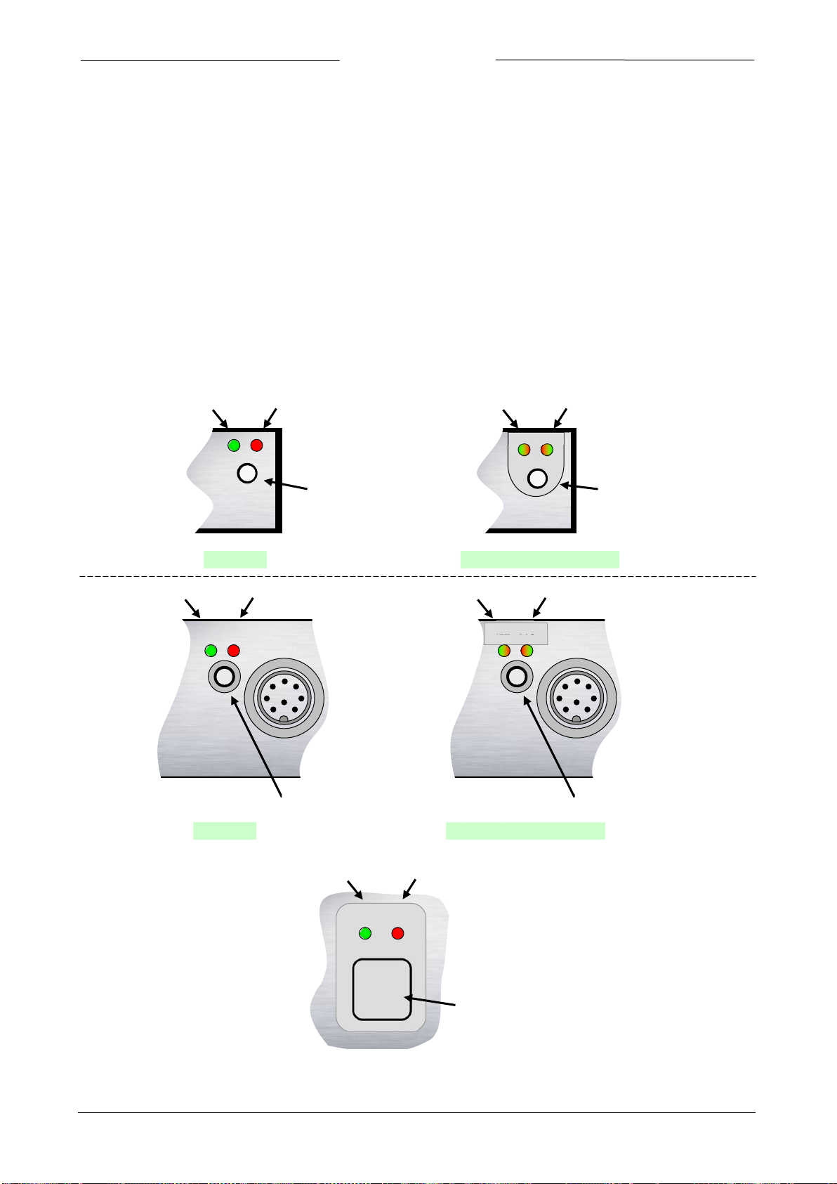
BRONKHORST®
GREEN
RED
MICRO-
SWITCH
GREEN/RED
GREEN/RED
MICRO-
SWITCH
Normal
DeviceNet (MBC3)
GREEN
RED
MICRO-
SWITCH
Normal
GREEN/RED
GREEN/RED
MICRO-
SWITCH
DeviceNet (MBC3)
NET
MOD
STATUS
NET
MOD
STATUS
LAB casing
Industrial
casing
#
GREEN
RED
SWITCH
11 MANUAL INTERFACE: MICRO-SWITCH AND LED’S
11.1 GENERAL
The micro-switch on top of the digital instrument can be used to start a certain function at the instrument. When the
switch is pressed down, both LED’s will start indicating different patterns in a loop. The switch has to be pressed down
until the 2 LED’s are indicating the right pattern. Then the switch has to be released and the choice has been made.
Normally (when the switch is not pressed) the green and red LED are used for mode indication on digital instruments
(FLOW-BUS / PROFIBUS-DP / DeviceNet / Modbus/EtherCAT).
11.1.1 LED and switch locations
Page 41 Operational instructions for digital multibus instruments 9.17.023

11.2 LED’S INDICATIONS
Led
Time
Indication
Green
off
Continuous
Power-off or program not running
on
Continuous
Normal running/operation mode
Short
flash
0.1 sec on
2.0 sec off
Initialization mode (Init reset = 73)
For MBC3 type: no bus communication, safe state active.
normal
flash
0.2 sec on
0.2 sec off
Special function mode
Instrument is busy performing any special function. E.g. auto-zero or self-test
long flash
2.0 sec on
Special mode, see specific field bus for more details
FLOW-BUS
Not used
PROFIBUS-DP /Modbus
Not used
DeviceNet (MBC-II)
Idle state
DeviceNet (MBC3)
See special table below
EtherCAT
Not used
Red
off
Continuous
No error
Short
0.1 sec on
Special mode, see specific field bus for more details
FLOW-BUS
Node occupied: Re-install instrument
PROFIBUS-DP
No data-exchange between master and slave Automatic recovery
Modbus
Data is received or transmitted
DeviceNet (MBC-II)
Minor communication error
DeviceNet (MBC3)
See special table below
EtherCAT
Instrument is not in OP mode (see EtherCAT manual for details)
normal
0.2 sec on
Warning message.
See specific field bus for more details
FLOW-BUS
Waiting for communication
PROFIBUS-DP / Modbus
No details
DeviceNet (MBC-II)
No bus power
DeviceNet (MBC3)
See special table below
EtherCAT
Not used
long flash
2.0 sec on
See specific field bus for more details
FLOW-BUS
Not used
PROFIBUS-DP
A requested parameter is not available.
See troubleshoot in Profibus manual.
Modbus
For special service purpose only
DeviceNet (MBC-II)
Serious communication error; manual intervention needed
DeviceNet (MBC3)
See special table below
EtherCAT
Error detected in EtherCAT configuration (see EtherCAT manual
for details)
on
Continuous
Critical error message. A serious error occurred in the instrument.
Instrument needs service before further using.
Wink Mode Green Red Green Red turn by turn
slow
0.2 sec on
Wink mode
position in a (large) system
normal
wink
1.0 sec on
1.0 sec off
Alarm indication: minimum alarm, limit/maximum alarm; power-up alarm or limit exceeded
or batch reached.
fast
wink
0.1 sec on
0.1 sec off
Switch-released, selected action started
11.2.1 LED indications mode (no switch used)
0.1 sec off
BRONKHORST®
flash
flash
2.0 sec off
0.2 sec off
0.1 sec off
An error occurred of minor importance.
It would be wise to investigate the cause of this.
You are still able to work with your instrument.
wink
Page 42 Operational instructions for digital multibus instruments 9.17.023
0.2 sec off
By a command send via FLOW-BUS the instrument can “wink” with Led’s to indicate its

for this state
Led
Indication
Network status LED (NET)
Not powered/ Not
Off
Device is not online
• No network power present
Link OK, Online,
Connected
On
green
Device is online and has connections in the established state
• For a group 2 device it means that the device is allocated to a master.
Online, Not
Flashing
The device is online but has no connections in the established state.
For a group 2 device it means that the device is not allocated to a master.
Connection Time-
Flashing
0.5 sec off
One or more I/O connections are in timed-out state.
Critical link Failure
On
Failed communication device. The device has detected an error that has
bus off)
Module status LED (MOD)
No power
Off
There is no power applied to the device
Device operational
On
green
The device is operating in normal condition.
Device in Standby
Flashing
0.5 sec off
The device needs commissioning due to configuration missing, incomplete or
Unrecoverable fault
On
red
The device has an unrecoverable fault, may need replacing.
Device self testing
Flashing
red / green
The device is in self test.
0.5 sec on
0.5 sec off
Module and status LEDs sequence at power-up
Network LED (NET)
off
Module LED (MOD)
green
0.25 sec
Module LED (MOD)
red
0.25 sec
Module LED (MOD)
green
Network LED (NET)
green
0.25 sec
Network LED (NET)
red
0.25 sec
Network LED (NET)
off
11.2.2 LED indications mode (DeviceNet MBC3)
BRONKHORST®
online
connected
out
(The device needs
commissioning)
green
0.5 sec on
0.5 sec off
red
0.5 sec on
red
green
0.5 sec on
• The device has not been completed the Dup_MAC_ID test yet.
• The device may not be powered, look at module status LED
• The device has passed the Dup_MAC_ID test, is online but has no
established connections to other nodes
•
rendered it incapable of communicating on the network. (Duplicate MAC ID or
incorrect. The device may be in the standby state.
Page 43 Operational instructions for digital multibus instruments 9.17.023

BRONKHORST®
LED
Time
Indication
Green
Red off
off
0…1 sec
Pressing a switch shortly by accident will not cause unwanted reactions of instrument.
off
off
1…4 sec
In case of min/max alarm or counter batch reached:
See specific field bus for more details.
FLOW-BUS
When address is occupied:
Automatic installation on FLOW-BUS.
PROFIBUS-DP / Modbus
Not used
DeviceNet (MBC-II)
Not used
DeviceNet (MBC3)
Not used
EtherCAT
Not used
off
on
4…8 sec
Reset instrument
During a start-up the instrument will perform a self-test
on
off
8…12 sec
Auto-zero
least 30 minutes!
on
on
12…16 sec
Set instrument in the FLASH mode
This mode will be indicated by both LED’s off when instrument is normally powered
LED
Time
Indication
Green
Red
off
off
0…4 sec
No action
instrument.
off
normal flash
0.2 sec off
4…8 sec
Restore parameters
final test at BHT production.
normal flash
off
8…12 sec
See specific field bus for more details.
FLOW-BUS
Auto install to bus Instrument will install itself
to a (new) free node-address on the FLOW-BUS.
PROFIBUS-DP / Modbus
Not used
DeviceNet (MBC-II)
Not used
DeviceNet (MBC3)
Not used
EtherCAT
Not used
normal flash
normal flash
12…16 sec
For MBC-II type of instruments, the default address will be set immediately.
See specific field bus for default installation address:
FLOW-BUS
Node-address = 0
PROFIBUS-DP
Station address = 126
DeviceNet (MBC-II)
MAC-ID = 63
11.2.3 LED indications using micro-switch at normal running mode of an instrument
When the switch is pressed-down both LED’s will be switched-off for function selection. As long as the switch will be
pressed-down, there will be a change in indication by the 2 LED’s after each 4 seconds. The moment the user
recognizes the indication (LED-pattern) for the function he wants, he must release the switch. Now the wanted
function is triggered.
Reset alarm (only if reset by keyboard has been enabled)
Instrument program will be restarted and all warning and error message will be cleared.
Instrument will be re-adjusted for measurement of zero-flow (not for pressure
meter/controller)
NOTE: First make sure there is no flow and instrument is connected to power for at
11.2.4 LED indications using micro-switch at power-up situation
Here is described what the indications are for the functions to be performed at power-up situation of an instrument.
This can be realized by pressing the switch first and while pressing, connecting the power. These actions have a more
‘initializing’ character for the instrument.
Pressing a switch shortly by accident will not cause unwanted reactions of the
0.2 sec on,
0.2 sec on,
0.2 sec off
All parameter settings (except field bus settings) will be restored to situation of
0.2 sec on,
0.2 sec off
Page 44 Operational instructions for digital multibus instruments 9.17.023
0.2 sec on,
0.2 sec off
The default address will be set after leaving this mode (approx. 60 sec)

BRONKHORST®
For MBC3 type of instruments the “configuration mode” is activated*
*MBC3 type instruments have additional functionality for Remote/manual install. It also sets the baud
This is called the “configuration mode”
The easiest way to set an address / baud rate is by using the rotary switches on the instrument (if
are not in the soft-address position.
1 6
Tens
Green LED
Use of “tens” and “unit”
Address
Unit
Red LED
rate and bus type for the main connector back to its default value as is 38K4 and type RS232.
11.3 MICRO-SWITCH USE FOR READING / SETTING ADDRESS / MAC-ID AND BAUDRATE
11.3.1 General
The micro-switch can be used for several functions. The function it triggers may be depending on the present field
bus. Use the micro-switch always in combination with the LED’s to prevent errors. The following functions can be
triggered with the micro-switch.
• Set instrument to default installation address/MAC-ID
• Read bus-address/MAC-ID and baud rate
• Change bus-address/MAC-ID and baud rate
• Read control mode
• Change control mode
To read or change settings by the micro-switch and LED’s, the number
can be separated in “tens” and “units”. The “tens” is the most left part
of the number. The “unit” is the most right decimal of the number.
present). Remember that the rotary switch setting overrides software setting at start-up if the switches
Page 45 Operational instructions for digital multibus instruments 9.17.023

BRONKHORST®
LED indications for bus-address/MAC-ID and baud rate (press switch 3x briefly)
LED
LED
Time
Indication
Green
Red
amount of count flashes
(0...12)
Off
0 ... 12 sec.
Maximum
tens in bus-address/MAC-ID for instrument
off
Amount of count flashes
(0...9)
0 ... 9 sec.
Maximum
units in bus-address/MAC-ID for instrument
amount of count flashes
(0...10)
amount of count flashes
(0...10)
0 ... 10 sec.
Maximum
baud rate setting for instrument
Baud rate index table for indication on the LED’s (in baud)
FLOW-BUS
PROFIBUS-DP
DeviceNet
Modbus
EtherCAT
1 2 187500
10
not detected
12000000
1
125000
1
9600
1
100000000
11.3.2 Readout bus-address/MAC-ID and baudrate:
Pressing the switch 3x briefly with intervals of max. 1 second in normal running/operation mode will trigger the
instrument to “show” its bus address/MAC-ID and baud rate. For indication the bus-address/MAC-ID the green LED
will flash the amount of tens and the red LED the amount of units in the number. For indication of baud rate setting,
both LED’s will flash. The flashes are called “count-flashes” and have a pattern of 0.5 sec. on, 0.5 sec. off.
Value zero will be indicated by a period of 1 sec. off (0.5 sec. off + 0.5 sec. off).
Examples:
• For bus address/MAC-ID 35 the green LED will flash 3 times and the red LED will flash 5 times.
• For bus address/MAC-ID 20 the green LED will flash 2 times and the red LED will flash 0 times.
• For bus address/MAC-ID 3 the green LED will flash 0 times and the red LED will flash 3 times.
• For bus address 126 the green LED will flash 12 times and the red LED will flash 6 times.
400000* 0 1
2
3
4
5
6
7
8
9
*MBC3 type instruments have additional baud rates available for the several field busses.
EtherCAT bus address is always ‘0’.
Examples:
• For PROFIBUS-DP baud rate readout of 12000000 Baud, both LED’s will flash 10 times.
• For DeviceNet baud rate readout of 250000 Baud, both LED’s will flash 2 times.
9600
19200
45450
93750
187500
500000
1500000
3000000
6000000
2
250000
3
500000
2
3
4
5
19200
38400
57600*
115200*
Page 46 Operational instructions for digital multibus instruments 9.17.023

BRONKHORST®
Procedure for changing bus-address/MAC-ID and baud rate
step
action
Indication
time
handling
1
Start
Press the switch 5x briefly with intervals of max. 1
second in normal running/operation mode.
2
Set tens of bus-
Green LED flashes
0.5 sec off
time-out:
Press switch and count green flashes for tens of
3
Set units of bus-
red LED flashes
0.5 sec off
time-out:
Press switch and count red flashes for units of
4
Set baud rate of field
both red
0.5 sec off
time-out:
Press switch and count red and green flashes for
Before each action of flash-counting, the LED’s to be used for counting will flash in a high frequency.
off and the counting sequence will start.
11.3.3 Change bus-address/MAC-ID and baudrate:
Pressing the switch 5x briefly with intervals of max. 1 second in normal running/operation mode. Within the time-out
period of 60 seconds it is possible to start changing the bus-address/MAC-ID of the instrument. For certain field bus
systems it is necessary to select the baud rate also. Other field bus systems only have one baud rate or the baud rate
setting will adapt to the setting of the master automatically. In these cases baud rate selection is not needed and will
be skipped.
address/MAC-ID
address/MAC-ID
bus communication.
Only for specific
types of field busses:
e.g. DeviceNet.
This part will be
skipped if no baud
rate needs to be
selected.
0.1 sec on
0.1 sec off
count-flashes
start when switch
is pressed:
0.5 sec on,
0.1 sec on,
0.1 sec off
count-flashes
start when switch
is pressed:
0.5 sec on,
and green
LED flashes
0.1 sec on,
0.1 sec off
count-flashes
start when switch
is pressed:
0.5 sec on,
60 sec
60 sec
60 sec
bus-address/MAC-ID.
Release when wanted amount has been count.
Counts up to max. 12 and than starts at 0 again.
When counting fails, keep switch pressed and
restart counting for next attempt.
bus-address/MAC-ID.
Release when wanted amount has been count.
Counts up to max. 9 and than starts at 0 again.
When counting failed, keep switch pressed and
restart counting for next attempt.
baud rate setting of the specific field bus.
Release when wanted amount has been count.
Counts up to max. 10 and than starts at 0 again.
When counting failed, keep switch pressed and
restart counting for next attempt.
Note: selection of 0 means: No change
Instrument returns to normal running/operation mode. Changes are valid when they are made within the time-out
times.
Value zero will be indicated by a period of 1 sec. off (0.5 sec. off + 0.5 sec. off).
When value zero is wanted, press switch shortly and release it again within 1 sec.
(Pattern: 0.1 sec on, 0.1 sec off). As soon as the switch is pressed-down, this LED (or both LED’s) will be
Page 47 Operational instructions for digital multibus instruments 9.17.023

BRONKHORST®
View current control mode (press switch 2x briefly)
LED
time
indication
green
red
amount of count flashes (0...2)
off
0 ... 2 sec. maximum
tens in control mode number
off
amount of count flashes (0...9)
0 ... 9 sec. maximum
units in control mode number
Change current control mode (press switch 4x briefly)
step
action
indication
time
handling
1
Set tens of
green LED flashes
0.5 sec off
time-out:
Press switch and count green flashes for tens of control
2
Set units of
red LED flashes
0.5 sec off
time-out:
Press switch and count red flashes for units of control
Before each action of flash-counting, the LED’s to be used for counting will flash in a high frequency.
off and the counting sequence will start.
11.4 MICRO-SWITCH USE FOR READING/CHANGING CONTROL MODE:
11.4.1 Read control mode
For switching between different functions in use of a digital meter or controller several modes are available. More
information about the available control modes can be found at parameter “Control mode”.
Pressing the switch 2x briefly with intervals of max. 1 second in normal running/operation mode will trigger the
instrument to “show” its control mode. For indication of the control mode number the green LED will flash the
amount of tens and the red LED the amount of units in the number. The flashes are called “count-flashes” and have a
pattern of 0.5 sec. on, 0.5 sec. off. The control mode numbers can be found at parameter “control mode”
Value zero will be indicated by a period of 1 sec. off (0.5 sec. off + 0.5 sec. off).
11.4.2 Change control mode:
For switching between different functions in use of a digital meter or controller several modes are available. More
information about the available control modes can be found at parameter “Control mode”.
Pressing the switch 4x briefly with intervals of max. 1 second in normal running/operation mode will trigger the
instrument to “change” its control mode.
setpoint / control
mode number
setpoint / control
mode number
Instrument returns to normal running/operation mode.
Changes are valid when they are made within the time-out times.
See parameter ‘Control mode’ for behaviour at power-up of the instrument.
Value zero will be indicated by a period of 1 sec. off (0.5 sec. off + 0.5 sec. off).
When value zero is wanted, press switch shortly and release it again within 1 sec.
0.1 sec on
0.1 sec off
Count-flashes
start when switch
is pressed:
0.5 sec on
0.1 sec on
0.1 sec off
Count-flashes
start when switch
is pressed:
0.5 sec on
60 sec
60 sec
mode number.
Release when wanted amount has been count.
Counts up to max. 2 and than starts at 0 again.
When counting fails, keep switch pressed and restart
counting for next attempt.
mode number.
Release when wanted amount has been count.
Counts up to max. 9 and than starts at 0 again. When
counting failed, keep switch pressed and restart counting
for next attempt.
(Pattern: 0.1 sec on, 0.1 sec off). As soon as the switch is pressed-down, this LED (or both LED’s) will be
Page 48 Operational instructions for digital multibus instruments 9.17.023

BRONKHORST®
12 TESTING AND DIAGNOSTICS
All digital instruments have facilities to run self-test procedures for diagnostics. Most of the instrument functions will
be tested automatically during start-up or normal running mode of the instrument. All results of testing or
malfunctioning will be stored in special diagnostics registers in the non-volatile memory of the instrument. These
registers will contain actual information about the functioning of the instrument. The red LED on top of the
instrument is used to indicate if there is something wrong. The longer the LED is burning (blinking) red, the more is
wrong with the instrument.
Page 49 Operational instructions for digital multibus instruments 9.17.023

BRONKHORST®
13 SERVICE
For current information on Bronkhorst and service addresses please visit our website:
Do you have any questions about our products? Our Sales Department will gladly assist you selecting the right product
for your application. Contact sales by e-mail:
For after-sales questions, our Customer Service Department is available with help and guidance. To contact CSD by email:
No matter the time zone, our experts within the Support Group are available to answer your request immediately or
ensure appropriate further action. Our experts can be reached at:
http://www.bronkhorst.com
sales@bronkhorst.com
support@bronkhorst.com
+31 573 45 88 39
Page 50 Operational instructions for digital multibus instruments 9.17.023
 Loading...