


Mass Flow
Table of contents
 Loading...
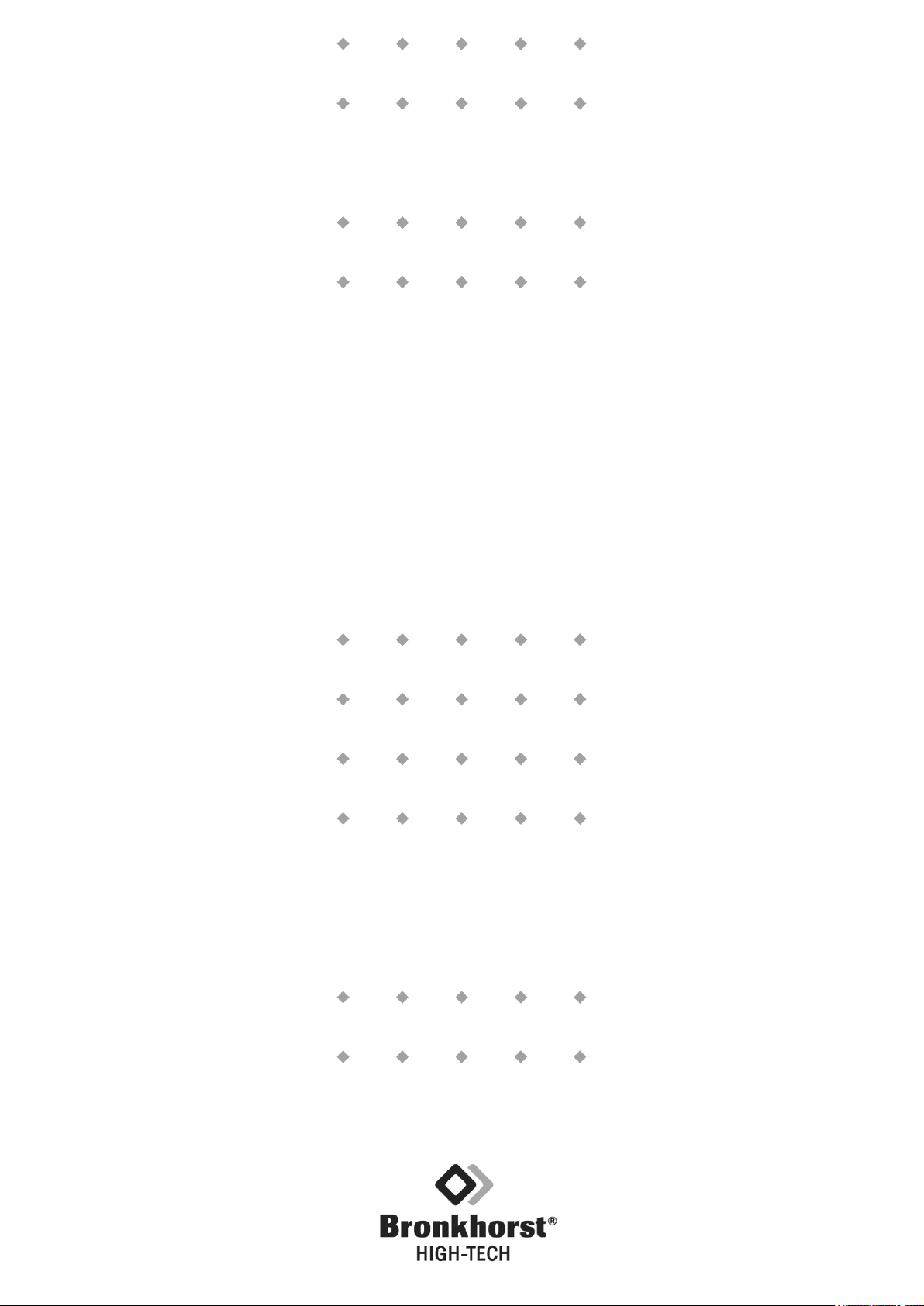
Instruction manual
Mass Flow / Pressure
meters and controllers
for gases and liquids
Doc. no.: 9.17.001O Date: 14-05-2014
ATTENTION
Please read this instruction manual carefully before installing and operating the instrument.
Not following the guidelines could result in personal injury and/or damage to the equipment.

BRONKHORST HIGH-TECH B.V.

BRONKHORST HIGH-TECH B.V.
Even though care has been taken in the preparation and publication of
the contents of this manual, we do not assume legal or other liability
for any inaccuracy, mistake, mis-statement or any other error of
whatsoever nature contained herein. The material in this manual is for
information purposes only, and is subject to change without notice.
Bronkhorst High-Tech B.V.
June 2011
Warranty
The products of Bronkhorst High-Tech B.V. are warranteed against
defects in material and workmanship for a period of three years from
the date of shipment, provided they are used in accordance with the
ordering specifications and the instructions in this manual and that
they are not subjected to abuse, physical damage or
contamination.Products that do not operated properly during this
period may be repaired or replaced at no charge. Repairs are normally
warranteed for one year or the balance of the original warranty,
whichever is the longer.
See also paragraph 9 of the Conditions of Sales.
The warranty includes all initial and latent defects, random failures,
and indeterminable internal causes.
It excludes failures and damage caused by the customer, such as
contamination, improper electrical hook-up, dropping etc.
Re-conditioning of products primarily returned for warranty service that
is partly or wholly judged non-warranty may be charged for.
Bronkhorst High-Tech B.V. prepays outgoing freight charges when any
part of the service is performed under warranty, unless otherwise
agreed upon beforehand.
However, if the product has been returned collect to Bronkhorst HighTech B.V., these costs are added to the repair invoice. Import and/or
export charges, foreign shipping methods/carriers are paid for by the
customer.

BRONKHORST HIGH-TECH B.V.
Short-Form Operation Instruction
Before installing your Mass Flow or Pressure
Meter/ Controller it is important to read the attached
label and check:
- flow/pressure rate
- fluid to be metered
- up and downstream pressures
- input/output signal
Check the red-coloured sticker and make sure the
test pressure is in agreement with normal safety
factors for your application.
Check if the piping system is clean. For absolute
cleanliness always install filters to assure a clean
liquid stream or a moisture and oil-free gas stream.
Install the Meter/Controller in the line and tighten the
fittings according to the instructions of the supplier of
the fittings. Choose the mounting position according
to the directions given in this manual.
Check the system for leaks before applying fluid
pressure
Electrical connections must be made with a standard
cable or according to the hook - up diagram in the
back of this manual.
Apply power to the instrument and allow for approx.
30 minutes to warm-up and stabilize. This may be
done with or without fluid pressure, applied to the
system.
Your instrument is now ready for operation.

BRONKHORST HIGH-TECH B.V.
TABLE OF CONTENTS
1. Introduction
1.1 General description ..................................................................................................................... page 7
1.1.1 Gas flow ..................................................................................................................................... page 7
1.1.2 Liquid flow .................................................................................................................................. page 7
1.1.3 Pressure ..................................................................................................................................... page 7
1.2 Housings .................................................................................................................................... page 7
1.2.1 EL-FLOW , EL-PRESS (Euro-style) ........................................................................................... page 7
1.2.2 Liquid flow meters / controllers .................................................................................................. page 7
1.3 Valves ........................................................................................................................................ page 8
1.3.1 Laboratory style ......................................................................................................................... page 8
1.3.2 Industrial style ............................................................................................................................. page 8
1.4 Sensor principles ....................................................................................................................... page 8
1.4.1 Gasflow sensors ........................................................................................................................ page 8
1.4.2 Liquid flow sensors .................................................................................................................... page 8
1.4.3 Pressure sensor ......................................................................................................................... page 9
1.5 Valve principles .......................................................................................................................... page 9
1.5.1 Solenoid valve ............................................................................................................................ page 9
1.5.2 Vary-P valve ............................................................................................................................... page 9
1.5.3 Pilot operated valve ................................................................................................................... page 10
1.5.4 Bellows valve ............................................................................................................................. page 10
1.6 Sensors and laminar flow devices ............................................................................................. page 10
1.7 Electronics ................................................................................................................................. page 11
1.8 Conversion factors ..................................................................................................................... page 12
1.8.1 Gas conversion factors .............................................................................................................. page 12
1.8.2 Liquid conversion factors ........................................................................................................... page 14
1.8.3 Software for conversion factor calculation .................................................................................. page 14
2. Installation
2.1 Receipt of equipment ................................................................................................................. page 15
2.2 Return shipment ......................................................................................................................... page 15
2.3 Service ....................................................................................................................................... page 15
2.4 Mounting .................................................................................................................................... page 15
2.5 In-line filter ................................................................................................................................. page 16
2.6 Fluid connections ....................................................................................................................... page 16
2.7 Piping ......................................................................................................................................... page 16
2.8 Electrical connections ................................................................................................................ page 17
2.9 Caution ....................................................................................................................................... page 17
2.10 Supply pressure ......................................................................................................................... page 17
2.11 System purging .......................................................................................................................... page 17
2.12 Seals .......................................................................................................................................... page 17
2.13 Equipment storage ..................................................................................................................... page 17
2.14 Electromagnetical compatibility ................................................................................................. page 18
2.14.1 Conditions for compliance with EMC requirements .................................................................... page 18

BRONKHORST HIGH-TECH B.V.
3. Operation
3.1 General ...................................................................................................................................... page 20
3.2 Power and warm-up ................................................................................................................... page 20
3.3 Zeroing ....................................................................................................................................... page 20
3.4 Start-up ...................................................................................................................................... page 20
3.5 Operating conditions .................................................................................................................. page 20
3.6 Instrument performance ............................................................................................................. page 21
3.6.1 Sensors ...................................................................................................................................... page 21
3.6.2 Controllers .................................................................................................................................. page 21
4. Maintenance
4.1 General ...................................................................................................................................... page 22
4.2 Gas flow sensor ......................................................................................................................... page 22
4.3 Liquid flow sensor ...................................................................................................................... page 22
4.4 Pressure sensor ......................................................................................................................... page 22
4.5 Controllers .................................................................................................................................. page 22
4.6 Control valves ............................................................................................................................ page 22
4.6.1 Solenoid valves ........................................................................................................................... page 22
4.6.2 Vary-P valve ................................................................................................................................ page 23
4.6.3 Pilot operated valve .................................................................................................................... page 23
4.6.4 Bellows valve .............................................................................................................................. page 23
4.7 K
4.7.1 For gases ................................................................................................................................... page 24
4.7.2 For liquids .................................................................................................................................. page 24
4.8 Maximum pressure drop ............................................................................................................ page 25
4.9 Calibration procedure ................................................................................................................. page 26
-value calculation ................................................................................................................... page 24
v
5. Troubleshooting
5.1 General ...................................................................................................................................... page 27
5.2 Troubleshooting summary ......................................................................................................... page 27
Appendices
1 Gasconversion table
2 Enclosures
BRONKHORST HIGH-TECH B.V.
1 Introduction
1.1 General description
1.1.1 Gas flow
The Bronkhorst High-Tech B.V. series mass flow meter for gases is an accurate device for measuring gas
flows up to 700 bar depending on body rating, virtually independent of pressure and temperature changes.
The system can be completed with a control valve and flexible readout to measure and control gas flows
from 3 ml
/min up to several thousand m
n
For a limited flow range a metal sealed model is available.
1.1.2 Liquid flow
The Bronkhorst High-Tech B.V. mass flow meter for liquids is an accurate device for measuring liquid flows
up to 400 bar, virtually independent of pressure and temperature changes. The system can be completed
with a control valve to measure and control liquid flows.
1.1.3 Pressure
The Bronkhorst High-Tech B.V. pressure meter measures pressures from 100 mbar up to 400 bar depending
on body rating, either absolute pressure or gauge pressure and in the range 0 to 15 bar differential pressure
too. The pressure controller controls pressure with a very high accuracy and repeatability. The controller is
available in forward control (P-600 series) and backward control (P-700 series).
The flow going through the pressure controller depends on up and downstream pressures, the orifice
diameter of the valve and kind of fluid.
1.2 Housings
Each instrument housing style incorporates several provisions to comply with EMC requirements.
1.2.1 EL-FLOW® , EL-PRESS (Euro-style)
The p.c.board is placed in a metalized plastic cover. For electrical connection
the instrument has a male 9-pin miniature sub-D connector. These instruments
are suited for indoor (dry) applications, like laboratories and in well protected
(OEM) housings.
1.2.2 Liquid flow meter / controller
The LIQUI-FLOW® models for up to 1000 g/h. This is a fully aluminium casted
instrument, which means that the instrument is formed by the housing.
This model has an IP-65 ingress protection class. For electrical connection a
round male 8-pin DIN connector is incorporated in the design.
The instrument is suited for light industrial (outdoor) use.
3
/h, depending on the specific type of instrument.
n
9.17.001 page 7
BRONKHORST HIGH-TECH B.V.
V K
c
signal
p m
= ⋅ ⋅
Φ
1.3 Valves
Two solenoid housing models can be distinguished. The basic mechanical design of both models is the
same. Valves are used as separate units, or integrated with a meter to form a complete control unit. The
solenoid versions are:
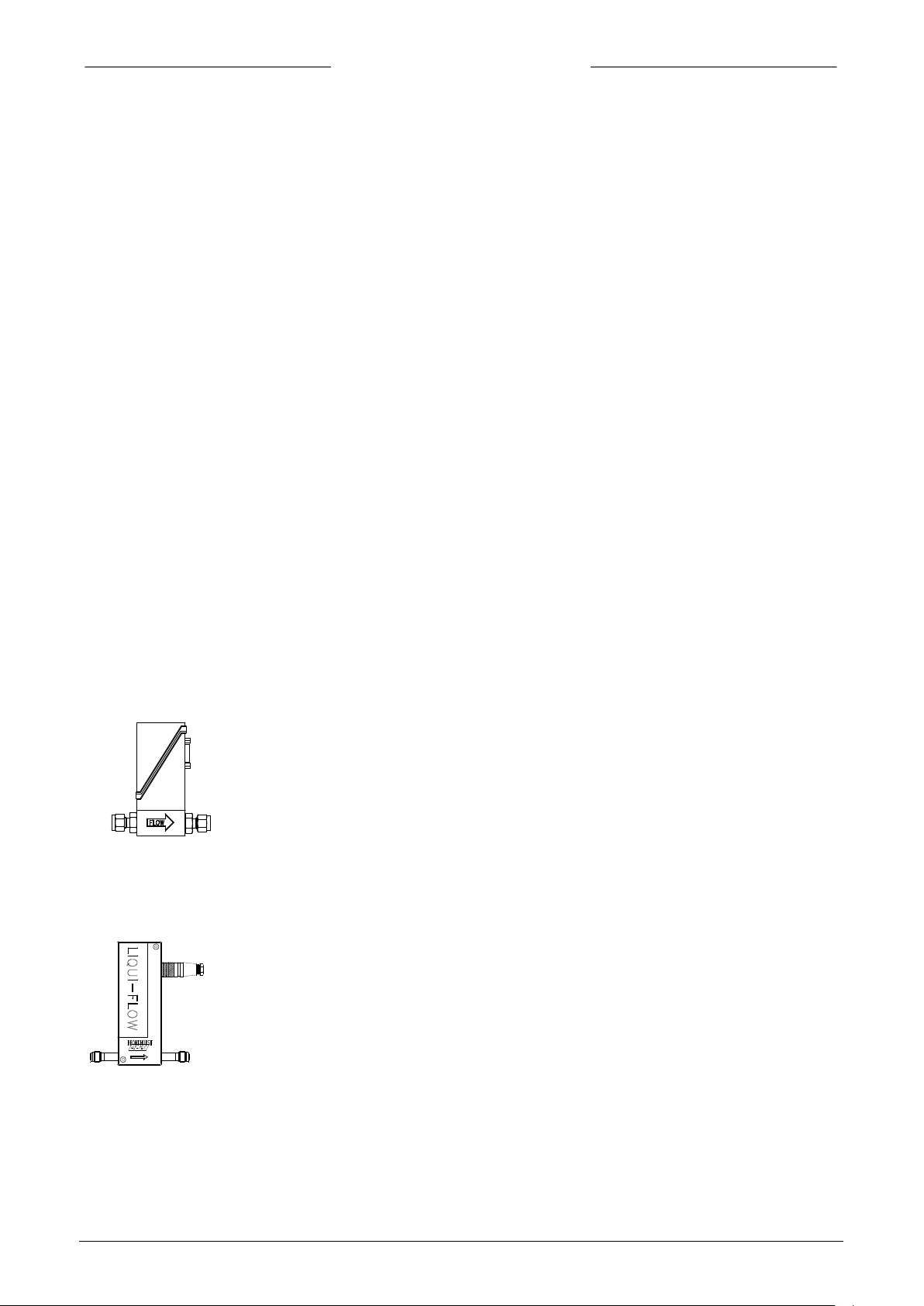
1.3.1 Laboratory style
The solenoids of these valves have an IP-50 ingress protection class.
This means that the valves are suited for indoor (dry) use.
1.3.2 Industrial style
The solenoids of these valves have an IP-65 ingress protection class. This
means that they are suited for light industrial (outdoor) use.
1.4 Sensor principles
1.4.1 Gas flow sensors
All gasflow sensors operate according to the same principle. They are operating on a principle of heat
transfer by sensing the delta-T along a heated section of a capillary tube. Part of the total flow is forced
through the capillary by means of a laminar flow device in the main stream generating a delta-p.
The design of the laminar flow device is such that flow conditions in both the capillary and laminar flow
device are comparable, thereby resulting in proportional flow rates through the meter. The delta-T sensed by
the upstream and downstream temperature sensors on the capillary depends on the amount of heat
absorbed by the gas flow.
The transfer function between gas mass flow and signal can be described by the equation:
= output signal
V
signal
= specific heat
c
p
K = constant factor
= mass flow
Φ
m
The temperature sensors are part of a bridge circuit and the imbalance is linearised and amplified to the
desired signal level.
1.4.2 Liquid flow sensor
- The LIQUI-FLOW mass flow meter for flow rates up to about 1000 g/h is basically a tube of stainless
steel without any built-in obstructions, internal diameter approx 1 mm. This tube is part of a completely
casted aluminium housing. An important part of the instrument is formed by two legs of tubing;
an upstream section and a downstream section.
On these two legs the heater/sensor arrangement of patented design is placed. The sensor measures the
page 8 9.17.001
BRONKHORST HIGH-TECH B.V.
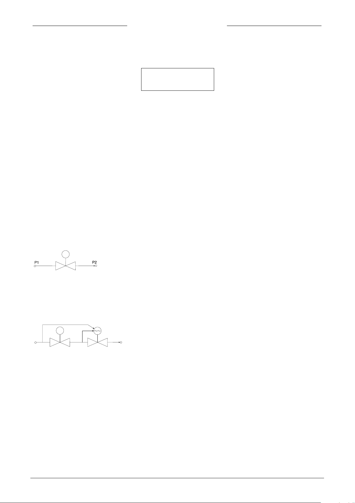
flow control
valve
flow control
valve
pressure
compensating
valve
P2
P1
mp
c
K
Φ⋅
⋅
temperature difference between the upstream and the downstream leg of the measuring tube by means
of a thermopile. The simplified transfer function can be described according to the following equation:
V
signal
=
V
signal
= output signal
K = constant factor
= specific heat
c
p
= mass flow
Φ
m
1.4.3 Pressure sensor
The EL-PRESS pressure sensor is formed by a piezoresistive bridge on the surface of a silicon crystal.
The sensor is mounted in a stainless steel construction and separated from the fluid by a thin metal
membrane. The chamber around the sensor is filled with oil to couple the pressure from the fluid to the
sensor.
1.5 Valve principles
Control valves are not designed to provide positive shut-off, although some models have excellent
capabilities for this purpose.
It is recommended to install a separate shut-off valve in the line if so required. Also pressure surges, as may
occur during system pressurisation must be avoided. The following models can be distinguished:
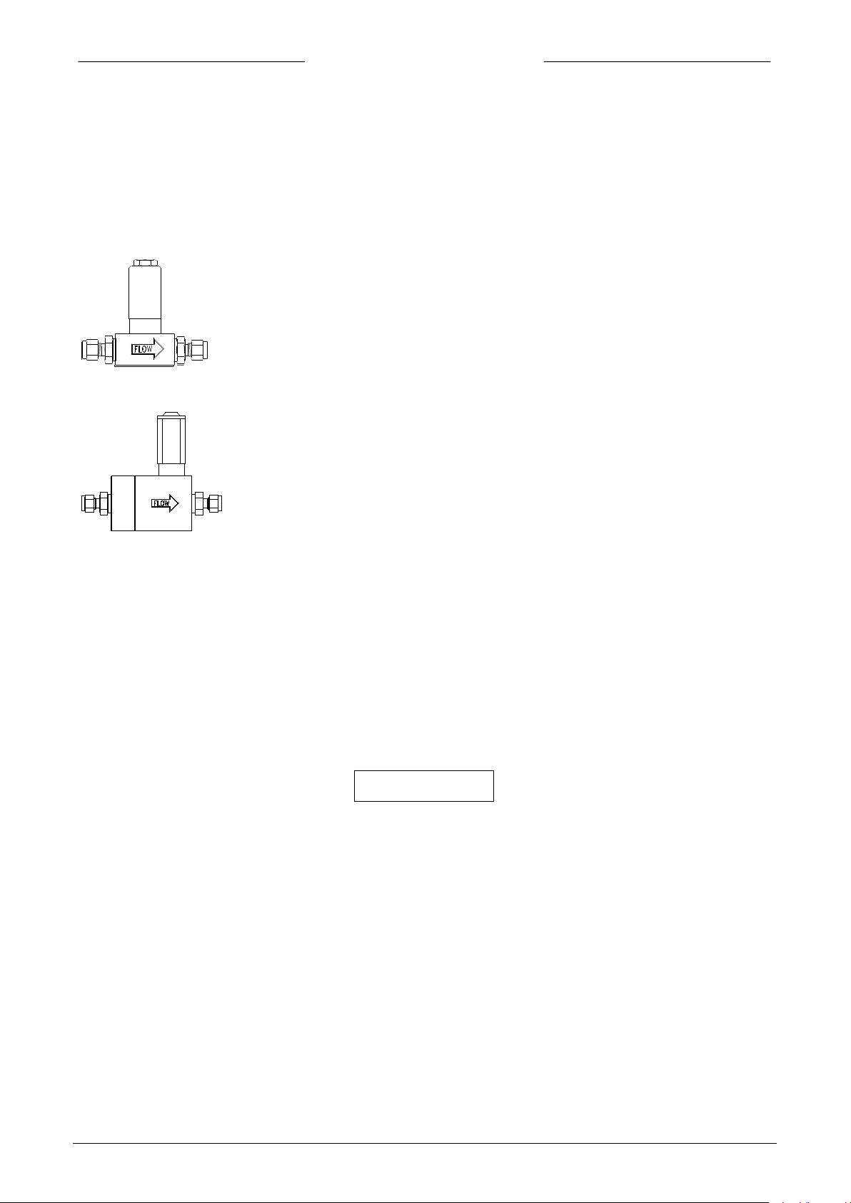
1.5.1 Solenoid valve
This is considered to be the standard (direct operated) control valve. In
general it is a normally closed solenoid valve. The plunger is lifted by
the force of the magnetic field of the coil. The orifice under the plunger
is removable for optimising the orifice diameter. Also a normally opened
solenoid valve is available.
1.5.2 Vary-P valve
For process conditions where up- and downstream pressures vary
much, a special type of valve, VARY-P has been designed. This valve
consists of two valves, a solenoid operated control valve and a fixed
adjusted pressure compensation valve.
9.17.001 page 9
Loading...