


Modbus slave interface
Table of contents
 Loading...
Instruction manual
Modbus slave interface
for digital
Mass Flow / Pressure instruments
Doc. no.: 9.17.035U Date: 16-10- 2014
ATTENTION
Please read this instruction manual carefully before installing and operating the instrument.
Not following the guidelines could result in personal injury and/or damage to the equipment.
Head Office: Nijverheidsstraat 1a, NL-7261 AK Ruurlo, The Netherlands, Tel. +31 573 458800, info@bronkhorst.com

BRONKHORST®
Important information. Discarding this information could cause injuries to people or
Instrument or installation.
Disclaimer
Even though care has been taken in the preparation and publication of the contents of this manual, we do not assume
legal or other liability for any inaccuracy, mistake, mis-statement or any other error of whatsoever nature contained
herein. The material in this manual is for information purposes only, and is subject to change without notice.
Bronkhorst High-Tech B.V.
July 2011
Symbols
damage to the
Helpful information. This information will facilitate the use of this instrument.
Additional info available on the internet or from your local sales representative.
Warranty
The products of Bronkhorst High-Tech B.V. are warranteed against defects in material and workmanship for a period
of three years from the date of shipment, provided they are used in accordance with the ordering specifications
and the instructions in this manual and that they are not subjected to abuse, physical damage or
contamination. Products that do not operate properly during this period may be repaired or replaced at no charge.
Repairs are normally warranted for one year or the balance of the original warranty, whichever is the longer.
See also paragraph 9 of the Conditions of sales:
http://www.bronkhorst.com/files/corporate_headquarters/sales_conditions/en_general_terms_of_sales.pdf
The warranty includes all initial and latent defects, random failures, and undeterminable internal causes.
It excludes failures and damage caused by the customer, such as contamination, improper electrical hook-up, physical
shock etc.
Re-conditioning of products primarily returned for warranty service that is partly or wholly judged non-warranty may
be charged for.
Bronkhorst High-Tech B.V. or affiliated company prepays outgoing freight charges when any party of the service is
performed under warranty, unless otherwise agreed upon beforehand. However, if the product has been returned
collect to our factory or service center, these costs are added to the repair invoice. Import and/or export charges,
foreign shipping methods/carriers are paid for by the customer.
Page 2 Modbus interface 9.17.035

BRONKHORST®
Table of contents
1 GENERAL PRODUCT INFORMATION ................................................................................................. 4
1.1 INTRODUCTION ................................................................................................................................................ 4
1.2 MULTIBUS TYPES .............................................................................................................................................. 4
1.3 REFERENCES TO OTHER APPLICABLE DOCUMENTS ..................................................................................................... 5
1.3.1 Manuals and user guides: ........................................................................................................................... 5
1.3.2 Technical Drawings: .................................................................................................................................... 5
1.3.3 Software tooling: ........................................................................................................................................ 5
1.4 SHORT FORM START-UP ..................................................................................................................................... 6
2 FIELD BUS INSTALLATION ................................................................................................................. 7
2.1 GENERAL ........................................................................................................................................................ 7
2.2 MODBUS CONNECTOR ....................................................................................................................................... 7
2.2.1 Shielded RJ45 modular jack ......................................................................................................................... 7
2.2.2 Shielded a coded M12 connector ................................................................................................................ 8
2.3 MODBUS CABLES AND T-PARTS ........................................................................................................................... 9
2.3.1 RJ45 FTP cables ........................................................................................................................................... 9
2.3.2 M12 DeviceNet drop cables ...................................................................................................................... 10
2.4 TERMINATION ................................................................................................................................................11
2.4.1 Termination resistors ................................................................................................................................ 11
2.4.2 Biasing resistors ........................................................................................................................................ 11
3 CHANGING SLAVE ADDRESS AND BAUD RATE ................................................................................ 13
3.1 VIA ROTARY SWITCHES ON THE SIDE OF THE INSTRUMENT (IF PRESENT) ........................................................................13
3.2 VIA RS232: FLOWFIX ......................................................................................................................................13
3.3 VIA RS232: OTHER PROGRAMS ..........................................................................................................................14
3.4 VIA MICRO-SWITCH AND LED’S ON THE INSTRUMENT (IF PRESENT) .............................................................................14
3.4.1 Readout bus-address/MAC-ID and baud rate: .......................................................................................... 14
3.4.2 Change bus-address and baud rate: ......................................................................................................... 15
3.5 BY USER INTERFACE (IF PRESENT) ........................................................................................................................15
4 FUNCTIONAL DESCRIPTION ............................................................................................................ 16
4.1 GENERAL .......................................................................................................................................................16
4.2 IMPLEMENTATION CLASS ...................................................................................................................................16
4.3 RESPONSE TIME ..............................................................................................................................................17
4.4 SUPPORTED MODBUS FUNCTIONS .......................................................................................................................17
4.4.1 Read Holding Registers (03) ...................................................................................................................... 17
4.4.2 Write Single Register (06) ......................................................................................................................... 17
4.4.3 Write Multiple Registers (16) .................................................................................................................... 17
4.4.4 Diagnostics (08) ........................................................................................................................................ 18
4.4.5 Report Slave ID (17) .................................................................................................................................. 18
4.4.6 Available parameters ................................................................................................................................ 19
5 TROUBLESHOOTING ...................................................................................................................... 21
5.1 VISUAL DIAGNOSTICS .......................................................................................................................................21
5.2 STEP-BY-STEP .................................................................................................................................................21
5.3 BUS DIAGNOSTICS STRING .................................................................................................................................22
6 SERVICE ........................................................................................................................................ 23
Page 3 Modbus interface 9.17.035

BRONKHORST®
The implementation of the Modbus interface is based on the following standards:
[2] Modbus_over_serial_line_V1_02.pdf December 20, 2006
1 GENERAL PRODUCT INFORMATION
1.1 Introduction
This manual covers the Modbus interface, which offers a direct
connection to Modbus for Bronkhorst
meters / controllers. The Modbus instrument will behave as a slave. This
means all communication (instructions / readout) will be performed by a
master device on the same Modbus system. Mostly this will be a PC
controlling a process. This manual explains how to install a Bronkhorst
instrument to your Modbus system.
1)
Bronkhorst: This includes Bronkhorst High-Tech B.V. , Bronkhorst Cori-Tech B.V. and
M+W Instruments GmbH.
More detailed information about Modbus can be found at www.modbus.org or any website of the
(local) Modbus organisation of your country (when available).
1)
digital mass-flow / pressure
[1] Modbus_Application_Protocol_V1_1b.pdf December 28, 2006
1.2 Multibus types
In 2000 Bronkhorst developed their first digital instruments according to the
“multibus” principle. The basic pc-board on the instrument contained all of
the general functions needed for measurement and control, including alarm,
totalizing and diagnostic functions. It had analog I/O-signals and also an
RS232 connection as a standard feature. In addition to this there is the
possibility of integrating an interface board with DeviceNet™, Profibus-DP
Modbus , FLOW-BUS or EtherCAT protocol. The first generation (MBC-I) was
based on a 16 bit Fujitsu controller. It was superseded in 2003 by the
Multibus type 2 (MBC-II). This version was also based on the 16 bit Fujitsu controller but it had several improvements
to the MBC-I. One of them is the current steering of the valve. It reduced heat production and improved control
characteristics. The latest version Multibus controller type 3 (MBC3) is introduced in 2011. It is build around a 72MHz
32 bit NXP ARM controller. It has AD and DA controllers on board which makes it possible to measure noise free and
control valves without delays. The internal control loop runs 6 times faster compared to the MBC-II therefore control
stability has improved significantly. It also has several improved functions like reverse voltage protection, inrush
current limitation and overvoltage protection.
MBC3 instruments can be recognised by the “MBC3” placed on lower left side
of the instrument label (see example).
®
,
Page 4 Modbus interface 9.17.035

BRONKHORST®
RS232 interface with
Bronkhorst High-Tech
Bronkhorst Cori-Tech
Bronkhorst Cori-Tech
Bronkhorst High-Tech
Document 9.17.022
Document 9.17.050
Document 9.17.044
Document 9.17.023
Document 9.17.024
Document 9.17.025
Document 9.17.026
Document 9.17.035
Document 9.17.027
General instructions
Instrument type based
Operational
instructions
Field bus specific
information
Document 9.17.031
M+W Instruments
Document 9.17.063
1.3 References to other applicable documents
Manuals and guides for digital instruments are modular. General instructions give information about the functioning
and installation of instruments. Operational instructions explain the use of the digital instruments features and
parameters. Field bus specific information explains the installation and use of the field bus installed on the
instrument.
1.3.1 Manuals and user guides:
General instructions digital Mass Flow / Pressure
General instructions CORI-FLOW
General instructions mini CORI-FLOW
General instructions digital LIQUI-FLOW L30
Instruction manual MASS-STREAM D-6300
Operational instructions
for digital multibus
Mass Flow / Pressure
instruments
FLOW-BUS interface
PROFIBUS–DP interface
DeviceNet interface
Modbus interface
FLOW-BUS protocol
EtherCAT interface
1.3.2 Technical Drawings:
Hook-up diagram laboratory-style Modbus (document nr. 9.16.064)
Hook-up diagram industrial style Modbus (document nr. 9.16.065)
Hook-up diagram CORI-FLOW Modbus (document nr. 9.16.066)
Hook-up diagram LIQUI-FLOW L30 digital Modbus (document nr. 9.16.075)
1.3.3 Software tooling:
FlowPlot
FlowView
FlowFix
FlowDDE
Page 5 Modbus interface 9.17.035
All these documents can be found at:
http://www.bronkhorst.com/en/downloads
BRONKHORST®
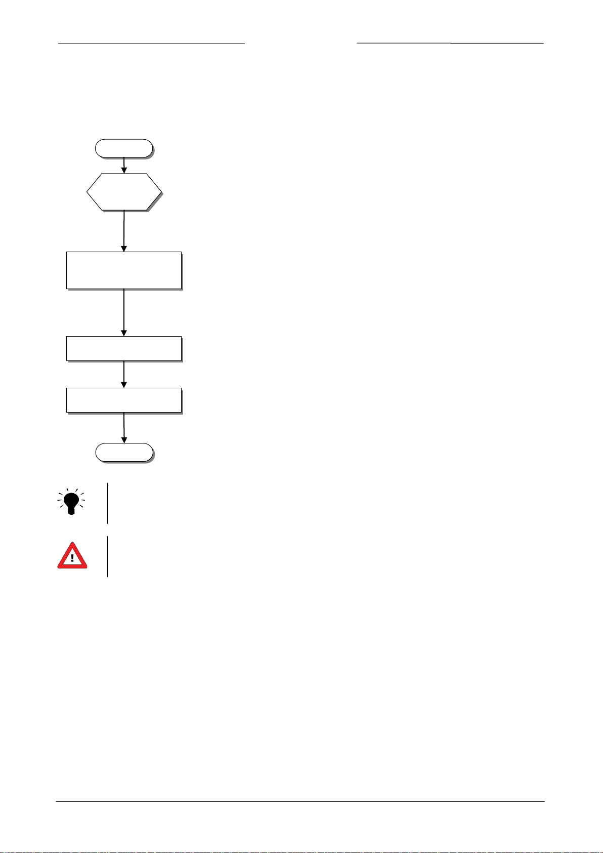
START
Master
present
Set Slave address and
baud rate of instrument
Make sure your Modbus master has been installed to the system
Instruments will be delivered to customers on address 1 and with a baud rate of
19200 baud.
switches on the instrument. Also y
address and baud rate via the RS232 connectio
instrument to apply the changes). Slave address and baud rate can also be changed
using the button (if present) on the instrument.
Connect instrument
Physically connect the instrument to the Modbus network.
Test
Test communication between your master and the instrument(s)
Ready
1.4 Short form start-up
All necessary settings for this module are already performed at Bronkhorst.
To follow next steps carefully is the quickest way to get this module operational in your own Modbus environment.
The easiest way to change the slave address is by use of the rotary
ou can use the FLOWFIX program to change Slave
n (it may be needed to restart the
Instruments with combined RS232 / RS485 signal lines and no user interface automatically detect the
bus type at start-up.
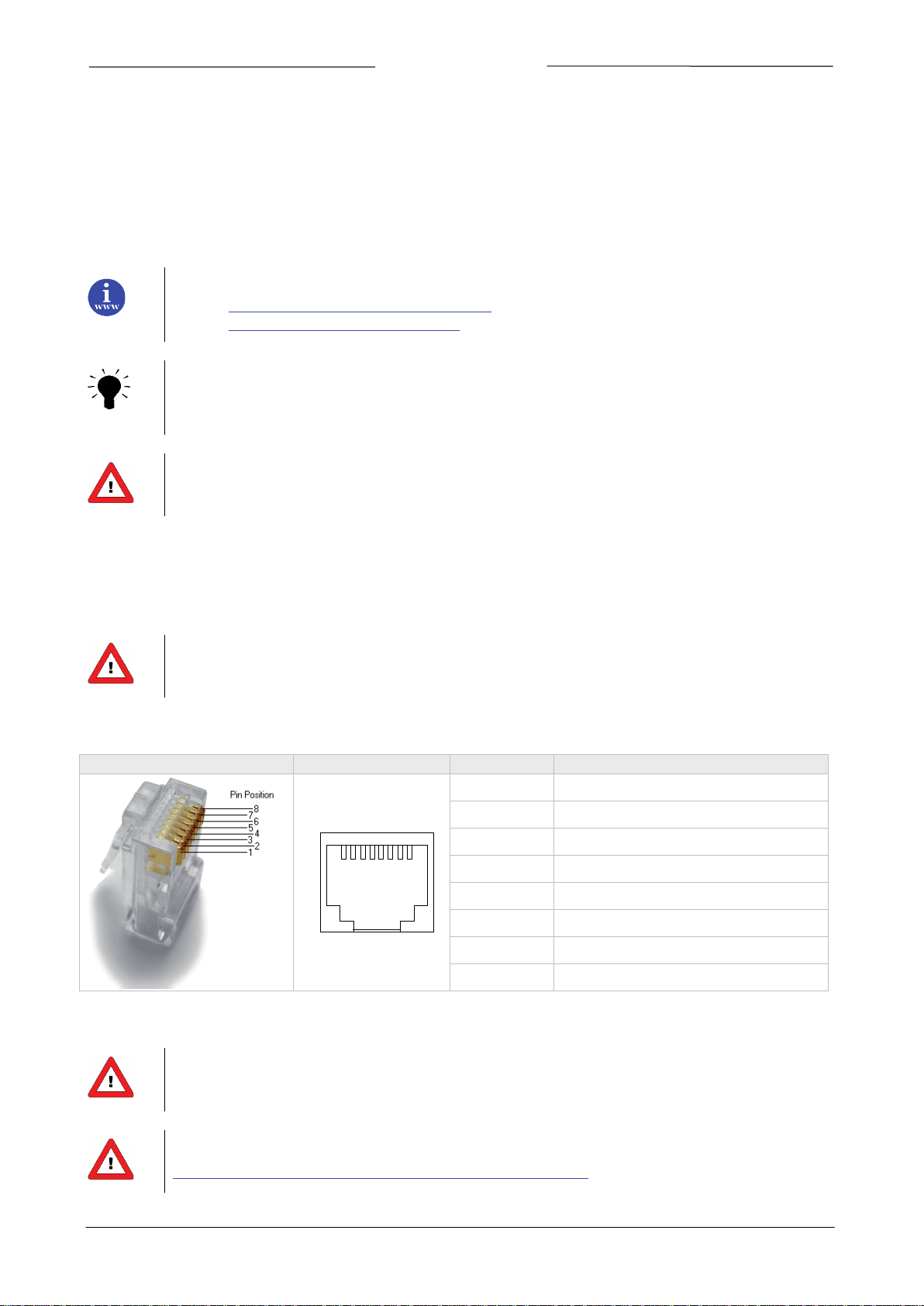
Warning: this device uses a vendor specific pin layout on the RJ45 connector that differs from the
Modbus recommended pin layout.
Page 6 Modbus interface 9.17.035
BRONKHORST®
1 8
The implementation of the Modbus interface is based on the following standards:
[2] Modbus_over_serial_line_V1_02.pdf December 20, 2006
Physical layer and communication protocol are detected automatically upon reception of messages.
protocol. After every power-up the communication detection mode is active.
RJ45 Connector
Receptable
Pin number
Description
2 FIELD BUS INSTALLATION
2.1 General
Modbus is a 3-wire, RS485-based field bus communication system for parameter value exchange. In this system each
instrument / device is equipped with a micro-controller for its own dedicated task but also for exchanging parameter
value information with other instruments / devices connected to the same Modbus system.
[1] Modbus_Application_Protocol_V1_1b.pdf December 28, 2006
These messages must be sent using the correct combination of physical layer and communication
Bronkhorst advices not to use more as 127 instruments in one bus system.
2.2 Modbus connector
2.2.1 Shielded RJ45 modular jack
Warning: this device uses a vendor specific pin layout on the RJ45 connector that differs from the
Modbus recommended pin layout.
The shielded RJ45 modular jack connector (for non IP65 applications) has the following pin configuration:
1 +15…24Vdc supply
2 0V
3 Shield
4 0V
5
6 0V (Modbus common)
7 D0 Modbus (A/A')
8 D1 Modbus (B/ B')
+15…24Vdc supply
The maximum contact rating for RJ45 connectors is 1.5A.
For MASS-VIEW instrument see manual 9.17.051 for pin layout.
Page 7 Modbus interface 9.17.035
http://www.bronkhorst.com/en/downloads/instruction_manuals/
Loading...