


Instruction manual
Digital readout and
control system E-7000
for analog and digital
instruments
Doc. no.: 9.17.004N Date: 25-07-2011
ATTENTION
Please read this instruction manual carefully before installing and operating the instrument.
Not following the guidelines could result in personal injury and/or damage to the equipment.

BRONKHORST HIGH-TECH B.V.

BRONKHORST HIGH-TECH B.V.
Even though care has been taken in the preparation
and publication of the contents of this manual, we do
not assume legal or other liability for any inaccuracy,
mistake, mis-statement or any other error of
whatsoever nature contained herein. The material in
this manual is for information purposes only, and is
subject to change without notice.
Bronkhorst High-Tech B.V.
July 2011
Warranty
The products of Bronkhorst High-Tech B.V. are
warranteed against defects in material and
workmanship for a period of three years from the date
of shipment, provided they are used in accordance
with the ordering specifications and the instructions in
this manual and that they are not subjected to abuse,
physical damage or contamination.
Products that do not operate properly during this
period may be repaired or replaced at no charge.
Repairs are normally warranteed for one year or the
balance of the original warranty, whichever is the
longer.
See also paragraph 9 of the Conditions of sales.
The warranty includes all initial and latent defects,
random failures, and undeterminable internal causes.
It excludes failures and damage caused by the
customer, such as contamination, improper electrical
hook-up, physical shock etc.
Re-conditioning of products primarily returned for
warranty service that is partly or wholly judged nonwarranty may be charged for.
Bronkhorst High-Tech B.V. prepays outgoing freight
charges when any party of the service is performed
under warranty, unless otherwise agreed upon
beforehand.However, if the product has been returned
collect to Bronkhorst High-Tech B.V., these costs are
added to the repair invoice. Import and/or export
charges, foreign shipping methods/carriers are paid
for by the customer.

BRONKHORST HIGH-TECH B.V.

BRONKHORST HIGH-TECH B.V.
TABLE OF CONTENTS
1 Introduction
1.1 General description ............................................................................................................ page 7
1.2 Model configuration ............................................................................................................page 7
1.3 Power supply......................................................................................................................page 8
1.4 In/output signals ................................................................................................................. page 8
1.4.1 Rearpanel connectors ........................................................................................................ page 8
1.4.2 Connection to measuring and controlling devices.............................................................. page 9
1.4.3 Connection to remote equipment ....................................................................................... page 9
1.4.3.1 Analog input/output signals................................................................................................. page 10
1.4.3.2 Relay contacts....................................................................................................................page 10
1.4.3.3 Reset input ......................................................................................................................... page 10
1.4.4 Connection to FLOW-BUS................................................................................................. page 10
1.4.4.1 RJ45 connector .................................................................................................................. page 10
1.4.5 RS232/FLOW-BUS interface.............................................................................................. page 10
1.4.5.1 General description ............................................................................................................ page 10
1.4.6 EMC and cables ................................................................................................................. page 11
1.5 Specifications ..................................................................................................................... page 12
1.5.1 Housings............................................................................................................................. page 12
1.5.2 EMC and housings ............................................................................................................. page 14
1.5.3 Electrical specifications ...................................................................................................... page 14
2 Installation
2.1 General............................................................................................................................... page 15
2.1.1 Receipt of equipment.......................................................................................................... page 15
2.1.2 Return shipment................................................................................................................. page 15
2.1.3 Service................................................................................................................................ page 15
2.1.4 Installation........................................................................................................................... page 15
2.1.5 Configuration ...................................................................................................................... page 15
2.1.6 Equipment storage ............................................................................................................. page 15
3 Operation of analog instruments
3.1 General information............................................................................................................ page 17
3.2 Start-up menu..................................................................................................................... page 18
3.3 Measure menu.................................................................................................................... page 20
3.4 Operation menu.................................................................................................................. page 22
3.5 Reset menu........................................................................................................................ page 24
3.6 Counter menu..................................................................................................................... page 26
3.7 Alarm menu........................................................................................................................ page 28
3.8 Instrument menu ................................................................................................................ page 30
3.9 Local menu.........................................................................................................................page 32
3.10 FLOW-BUS menu .............................................................................................................. page 34
3.11 Calibration with polynomial functions.................................................................................. page 36
3.11.1 General information............................................................................................................page 36
3.11.2 General form....................................................................................................................... page 36

BRONKHORST HIGH-TECH B.V.
3.11.3 Polynomial functions of sensor signal and setpoint............................................................ page 36
3.11.4 Presentation of parameters ................................................................................................ page 37
3.11.5 Using polynomial functions at readout/control unit............................................................. page 37
4 Operation of digital (FLOW-BUS) instruments.............................................. page 39
4.1 General information............................................................................................................ page 39
4.2 Startup and menu selection................................................................................................ page 40
4.3 Measure menu.................................................................................................................... page 42
4.4 Operation menu.................................................................................................................. page 44
4.5 Reset menu........................................................................................................................ page 46
4.6 Counter menu..................................................................................................................... page 48
4.7 Alarm menu........................................................................................................................ page 50
4.8 Instrument menu ................................................................................................................ page 54
4.9 Local menu.........................................................................................................................page 58
4.10 FLOW-BUS menu .............................................................................................................. page 60
4.11 Calibration with polynomial functions.................................................................................. page 63
4.11.1 General information............................................................................................................page 63
4.11.2 General form....................................................................................................................... page 63
4.11.3 Polynomial functions of sensor signal and setpoint............................................................ page 63
4.11.4 Presentation of parameters ................................................................................................ page 63
4.11.5 Using polynomial at readout/control unit............................................................................. page 64
5 Maintenance ................................................................................................................. page 65
6 Troubleshooting......................................................................................................... page 66
Appendices
1 System specific sections (if applicable)
2 Customer system description (if applicable)

BRONKHORST HIGH-TECH B.V.
1 INTRODUCTION
1.1 General description
The Bronkhorst High-Tech B.V. serie E-7000 is a modular digital readout and control system for (analog)
mass flow/pressure sensors and controllers. Basically a system consists of one or more (14 TE) single
channel readout/control modules.
The system can be expanded with additional (14 TE) modules like Ex-proof and heatercontrol for evaporator
systems. (For operation of any of these special functions the appropriate additional manuals should be
consulted).
1.2 Model configuration
(A)
E - 7 N N 0 - NN - NN - NN ..... etc.
Housing Code
½ 19" table top (42 TE)
19" table top (84 TE)
½ 19" rack (42 TE)
19" rack (84 TE)
Table top cassette (14 TE)
Panel mount casset t e (14 TE)
Other/Specifiy
Supply voltage Code
100 ... 240 Vac
220 ... 240 Vac
110 ... 120 Vac
24 Vac
24 Vdc
Other/Specify
Modules with blind front (14 TE) Code
Blind front only
Blind front + power supply (linked to module with mains entrance)
Blind front + power supply + mains ent rance + flow bus (incl. cable)
Blind front + power supply + RJ45 connect or for +15Vdc supply voltage
+ mains entrance (incl. cable)
Blind front + power supply + RJ45 connect or for +15Vdc supply voltage
( linked to module with mai ns entrance)
Modules with single channel Readout/Control panel (14 TE) Code
R/C-panel + power supply + mains entrance (incl. cable) analog model
R/C-panel + power supply (linked to module with mains entrance) analog model
R/C-panel (linked to module with power supply) analog model
R/C-panel + power supply + mains entrance (incl. Cable) digital model
R/C-panel + power supply (linked to module with main entrance) digital m odel
R/C-panel (linked to module with power supply) di gi tal model
Modules with Ex-proof functions (14 TE) Code
R/C-panel + transmitt er supply unit for MFM/EPT (Ex-proof)
R/C-panel + supply for MFM/EPT (Ex-proof) + valve with XB-coil
R/C-panel + supply for MFM/EPT (Ex-proof) + valve with XC-coil
Blind front + transmi tter supply unit for MFM/EPT (E x-proof)
Blind front + supply for MFM/EP T (Ex-proof) + valve with XB-coil
Blind front + supply for MFM/EP T (Ex-proof) + valve with XC-coil
Modules for temperature control for CEM-systems (14 TE) Code
Temp. R/C-panel + 10 W supply for low capacity CEM-sys t em
Temp. R/C-panel + 100 W supply for medium capacity CEM-system
Temp. R/C-panel + excl. supply f or hi gh capacity CEM-system
Temp. R/C-panel + 1000W supply / 230Vac W-303
Temp. R/C-panel + 1000W supply / 120Vac operation for W-303
Blind front + FLOW-BUS/RS232 interface
Blind front + FLOW-B US/PROFIBUS-DP interface
None
Other/Specify
1
2
3
4
5
6
9
0
1
2
3
4
9
(B) (C)
Modules
to be mounted in the
selected housing;
mounting order from
left to right
01
03
04
05
06
10
11
12
13
14
15
20
21
22
23
24
25
33
34
35
36
37
40
41
00
99
9.17.004 page 7

BRONKHORST HIGH-TECH B.V.
c
PE:ground
P
E
Code for external output/input signals :
Sensor output signal Code
0 - 5 Vdc
0 - 10 Vdc
0 - 20 mA dc (Sinking)
4 - 20 mA dc (Sinking)
15 - 20 mA dc
0 - 20 mA (Sourcing)
4 - 20 mA (Sourcing)
FLOW-BUS
Other/Specify
Module output signal Code
0 - 5 Vdc
0 - 10 Vdc
0 - 20 mA (Sourcing)
4 - 20 mA (Sourcing)
Other/Specify
Ext. setpoint/Module input si gnal Code
0 - 5 Vdc
0 - 10 Vdc
0 - 20 mA (Sinking input)
4 - 20 mA (Sinking input)
Other/Specify
A
B
C
D
E
F
G
R
Z
A
B
C
D
Z
A
B
C
D
Z
N N - A A A
Module
(see page 7)
1.3 Power supply
Each E-7000 series housing incorporates one or two power supplies.
System setup is such that the instruments that belong to the sytem can be powered.
For other applications or modifications your supplier should be consulted. The power input incorporates an
on/off switch and a fuse. For extra protection each power supply has a separate internal fuse.
1.4 In/output signals
If applicable, connection of cables carrying in- or/and output signals is further explained in the customer
system description (see appendices).
1.4.1 Rear panel connectors
for analog instruments:
FLOWBUS
INSTR
IN/OUT
3
1
2
1: +24Vdc/24 Va
2: 0Vdc/24 Vac
3: not connected
page 8 9.17.004

BRONKHORST HIGH-TECH B.V.
c
PE:ground
P
E
for digital instruments (FLOW-BUS):
FLOW-BUS
IN/OUT
IN/OUT
FLOW-BUS
3
IN/OUT
1: +24 Vdc/24 Va
2: 0 Vdc/24 Vac
3: not connected
2
1
1.4.2 Connection to measuring and controlling devices
The instrument connector (2) is a female sub-miniature 9-pin D-connector. The pin designation is according
to the Bronkhorst High-Tech B.V. standard for analog
instruments.
pinnumber description
1
2
3
4
5
6
7
8
9
not connected
sensor signal
setpoint signal
0 V valve
+ valve
- 15 Vdc supply
+ 15 Vdc supply
0 V/Common
ground (shield)
Sensor- and setpointsignals are also according to one of the Bronkhorst High-Tech B.V. standards.
signal
type sensor setpoint
A
0 - 5 Vdc
B
0 - 10 Vdc
C
0 - 20 mA (sinking)
D
4 - 20 mA (sinking)
F
0 - 20 mA (sourcing)
G
4 - 20 mA (sourcing)
0 - 5 Vdc
0 - 10 Vdc
0 - 5 Vdc
1 - 5 Vdc
0 - 20 mA
4 - 20 mA
1.4.3 Connection to remote equipment
The female in/out (1) (sub-miniature 9-pin) D-connector has the following pin configuration:
pinnumber description
1
2
3
4
5
6
7
8
9
output signal
input signal
0 V (common)
not connected
relay contact MC
relay contact NO
relay contact NC
reset input
ground (shield)
9.17.004 page 9

BRONKHORST HIGH-TECH B.V.
1.4.3.1 Analog input/output signals
Analog input signals should be connected to pin 2 (+) and 0 V/common.
Analog ouput signals are available at pin 1 (+) and 0 V/common.
Signals are according to one of the Bronkhorst High-Tech B.V. standards. The model configuration contains
a code, describing the input/output signals.
Notes:
a. Max. load current output (sourcing) : 375 Ohm
b. Min. load voltage ouput : 10 kOhm
c. Input load resistance (voltage) : 22K4
d. Input load resistance (current) (sinking) : 200 Ohm
e. Input load resistance (current) (sourcing) : 250 Ohm
1.4.3.2 Relay contacts
The (isolated) relay contacts are available at the following pins:
pin 5: common
pin 6: normally open
pin 7: normally closed
Note: contact arrangement during "power on"/"no alarm".
The specifications of the relay contacts are:
Contact arrangement : SPCO (Single Pole Changeover)
Contact rating : Switch voltage : 24 Vac/dc max.
Switch current : 0,2 A ac/dc max.
Switch power : 3 W/3 VA max.
1.4.3.3 Reset input
The reset input signal should be connected to pin 8 (+ V) and pin 3 (0 V/common).
Reset can be achieved by either pulling the + V input (pin 8) to 0 V (pin 3) by means of a contact or a
transistor, or by applying an active low logic signal to pin 8 (+ V) and pin 3 (0 V). The logic signal level should
be 5 V (high) or 0 V (low).
1.4.4 Connection to FLOW-BUS
1.4.4.1 RJ45 connector
The shielded RJ45 modular jack connector has the following pin configuration:
pinnumber description
1
2
3
4
5
6
7
8
+ 15 Vdc supply
0 V (ref to +15Vdc )
Shield
0 V (ref to +15Vdc )
+ 15 Vdc supply
0 V (RS485)
RS485 - B
RS485 - A
1.4.5 RS232/FLOW-BUS interface
1.4.5.1 General description
The RS232/FLOW-BUS interface is an interface between the FLOW-BUS and the RS232 V24 serial
(computer) port.
It will either be supplied as a separate enclosed unit with a FLOW-BUS connector and a RS232 connector or
as an integral 14TE module of your E-7000 readout and control system.
The converter offers communication with a baudrate up to 38,4 kbaud.
Communication software support is available. Consult manual RS232/Flow-Bus interface.
page 10 9.17.004

BRONKHORST HIGH-TECH B.V.
e
1.4.6 EMC and cables
All system setups described in this manual carry the CE-mark.
Therefore they have to comply with the EMC requirements as are valid for this kind of equipment.
However compliance with the EMC requirements is not possible without the use of proper cables and
connector assemblies.
For good results Bronkhorst High-Tech B.V. can provide standard cables. Otherwise follow the guidelines as
stated below. For cables with 9-pin sub D-connectors:
Fold the shield of the cable back over the cable (the shield must be around the cable).
20 mm
Wind a copper tape around the shield
Solder a black wire on the tape and
Connect to pin 9 of connector
copper tape
shielded cable
.g. LAPP LiYCY
8 mm
other wires
black wire
D-connector housing
metalized
connector
(shield)
NOTE:
For FLOW-BUS SFTP data (patch)cable connection to RJ45 connectors follow the instructions of the
supplier. It is important to use shielded twisted pair cables and shielded RJ45 modular jack connectors.
In case the system is electrically connected to another device (e.g. I/O connector to PLC), use shielded
cables.
Be sure not to disturb the integrity of the shielding of the cable, never use open wire terminals.
9.17.004 page 11

1.5 Specifications
1.5.1 Housings
½ 19" table top (42TE)
BRONKHORST HIGH-TECH B.V.
213.4 mm
235.4 mm
19" table top (84TE)
426.8 mm
448.8 mm
m
m
m
m
5
5
.
.
2
2
3
1
1
1
213.4 mm
m
m
m
m
5
5
.
.
2
2
3
1
1
1
m
m
m
m
5
5
.
.
2
8
3
3
2
2
238.5 mm
238.5 mm
m
m
m
m
5
.
0
2
4
3
1
1
m
m
m
m
5
.
0
2
4
3
1
1
426.8 mm
½19" rack mount (42TE)
213.4 mm
235.4 mm
m
m
m
m
5
5
.
.
2
8
3
3
2
2
m
m
m
m
5
5
.
.
2
2
3
1
1
1
213.4 mm
m
m
m
m
5
5
.
.
2
8
3
3
2
2
282.5
m
m
5
.
2
3
1
page 12 9.17.004

19" rack mount (84TE)
426.8 mm
448.8 mm
BRONKHORST HIGH-TECH B.V.
m
m
m
m
5
5
.
.
2
2
3
1
1
1
m
m
m
m
5
5
.
.
2
8
3
3
2
2
282.5
m
m
5
.
2
3
1
426.8 mm
table top cassette (14TE)
m
m
E
H
4
.
3
3
3
1
14 TE
76 mm
m
m
0
6
2
panel mount cassette(96x144mm for 14TE module)
90mm
m
m
5
.
3
3
m
1
m
0
3
2
14TE
96mm
E
4
H
4
1
3
230mm
233mm
m
m
4
.
3
3
1
260 mm
m
m
4
4
1
+0.8
92 mm
PANEL CUT OUT
m
m
0
.
1
+
8
3
1
96mm
9.17.004 page 13

BRONKHORST HIGH-TECH B.V.
1.5.2 EMC and housing
All electronic circuits and modules have been designed to meet the requirements needed to carry the
CE-mark.
However compliance with the (EMC) requirements is not possible without the use of properly
screened housings.
1.5.3 Electrical specifications
Input: see model configuration for input voltage
Supply voltage: 100 ... 240 Vac : 50 ... 60 Hz
220 ... 240 Vac : 50 ... 60 Hz
110 ... 120 Vac : 50 ... 60 Hz
24 Vac : ± 5 %/50 ... 60 Hz
24 Vdc : ± 5 %
Outputs of one power supply:
Mains powered and : + 15 Vdc/2A
24 Vac/dc powered - 15 Vdc/0,5A
+ 5 Vdc/1A nominal 30W
Temperature
Operating range : 0 ... + 50°C
Storage range : - 20 ... + 60°C
Fuse : consult system label
Note :
Never block ventilation holes.
Operation at high ambient temperatures over extended periods may lead to reduction of the operating
lifetime of your power supply / readout system
page 14 9.17.004

BRONKHORST HIGH-TECH B.V.
2 INSTALLATION
2.1 General
2.1.1 Receipt of equipment
Check the outside packing for damage incurred during shipment.
Should the packing box be damaged, then the local carrier must be notified at once regarding his liability, if
so required.
At the same time a report should be submitted to
BRONKHORST HIGH-TECH B.V.
RUURLO HOLLAND
Remove the envelope containing the packing list; carefully remove the equipment from the packing box.
Do not discard spare or replacement parts with the packing material and inspect the contents for damaged or
missing parts.
2.1.2 Return shipment
When returning material always describe problem and if possible the work to be done in a covering letter.
Important:
Do clearly note, on top of the package the custom clearance number of Bronkhorst High-Tech B.V.,
namely:
NL801989978B01
2.1.3 Service
If this equipment is not properly serviced, serious personal injury and/or damage to the equipment could
result. It is therefore important that servicing is performed by trained and qualified service personnel.
Bronkhorst High-Tech B.V. has a trained staff of servicemen available.
2.1.4 Installation
Before switching on power, please check if all external electrical connections with sensor/controllers and
FLOW-BUS (if necessary) are properly connected (consult Customers System Description).
If you receive a readout unit including sensor/controllers, the total system has been tested in full operation
under the nearest process-conditions.
For the electrical connection between sensor/controller and readout unit it is recommended to use the
standard Bronkhorst HI-TEC cable, which is an eight conductor shielded cable, complete with connectors.
2.1.5 Configuration
All readout and control modules are factory set, for the used Bronkhorst High-Tech sensors/controllers, as
described in your customer system description (see appendices).
2.1.6 Equipment storage
The equipment should be stored in its original packing in a cupboard warehouse or similar. Care should be
taken not to subject the equipment to excessive temperatures or humidity.
9.17.004 page 15

BRONKHORST HIGH-TECH B.V.
page 16 9.17.004

BRONKHORST HIGH-TECH B.V.
3 Operation of analog instruments
3.1 General information
Before operating your sytem be sure that it is setup to readout and control analog instruments.
Check: Model configuration; sensor output signal.
Use 'cursor' keys to scroll through the menu-structure and to select the required menu level.
The 'enter' key is used to acknowledge a selected setting and to enter a edited value and/or text.
Editing can be performed by using the 'cursor' keys to select the character to be edited ( ← / → ) and to scroll
through the available character set or units ( ↑ / ↓ ).
After power-up the display will show the usual start-up sequence for some seconds.
FLOW-BUS
analog instrument
9.17.004 page 17

BRONKHORST HIGH-TECH B.V.
3.2 Startup and menu selection
(8000 0000)
FLOW-BUS MENU
(7000 0000)
LOCAL MENU
(6000 0000)
INSTRUMENT MENU
ALARM MENU
COUNTER MENU
RESET MENU
(5000 0000)
(4000 0000)
(3000 0000)
(2000 0000)
OPERATION MENU
(0000 0000)
Loading
Parameters ...
Bronkhorst Hi-Tec
(0001 0000)
Checking flowbus
Please wait ...
(0002 0000)
(0003 0000)
SINGLE CHANNEL
STYLE D Vx.xx
MEASURE MENU
(1000 0000)
page 18 9.17.004

BRONKHORST HIGH-TECH B.V.
Menu descriptions
0001 0000 Startup screen showing company name
0002 0000 Startup screen showing communication check with FLOW-BUS in progress. Takes a short time
(few seconds), depending on system size. If the FLOW-BUS address of the module is occupied,
you can reinstall the module on a new address.
0003 0000 Startup screen showing software revision level
1000 0000 Measure menu or ‘Readout Display’ for reading the amount of flow/pressure, setpoint and/or
counter value. When there is an alarm- or counter limit reached it will be shown here. For editing
the setpoint/slave factor go down one level.
2000 0000 Operation menu for selecting setpoint source (and master/slave), fluidset and setpoint slope for
the device to be operated. Also for editing setpoint offset.
3000 0000 Reset menu for quick reset of counter and alarm by keyboard. Also password input location to
enable advanced use of this module.
4000 0000 Counter menu for configuration of all counter options. This menu is secured by means of a
password.
5000 0000 Alarm menu for configuration of all alarm options. This menu is secured by means of a
password.
6000 0000 Instrument menu for configuration of the instrument to be operated, such as instrument type,
capacity, sensor type, identification and fluid sets with calibration values. This menu is secured
by means of a password.
7000 0000 Readout menu for configuration of the measure menu. You can select the wanted information for
your display.
8000 0000 FLOW-BUS menu to install module on the FLOW-BUS or start/stop communication with the bus.
This menu is secured by means of a password.
9.17.004 page 19

3.3 Measure menu
BRONKHORST HIGH-TECH B.V.
(1200 0000)
EDIT SETPOINT:
xxx.xx (cursor)
MEASURE MENU
(1000 0000)
(1100 0000)
EDIT SETPOINT:
xxx.xx (step)
(1400 0000)
CHANGE SETPOINT:
SETPOINT ZERO
(1300 0000)
CHANGE SETPOINT:
SETPOINT FULL
page 20 9.17.004

BRONKHORST HIGH-TECH B.V.
Menu descriptions
1100 0000 Stepsize editor for editing setpoint/slave-factor by a 0.1% step up or down. By holding down
UP/DOWN key continuously, the step size will increase. Changes are used by the controller
immediately. What is displayed here in this menu depends on the selection of the setpoint
source. Analog setpoints can not be edited.
1200 0000 Cursor editor for editing setpoint/slave-factor by entering the exact (new) value. After pressing
'enter', the changes will be used by the controller. Could be used for large setpoint steps. What is
displayed here in this menu depends on the selection of the setpoint source. Analog setpoints
can not be edited.
1300 0000 Setpoint full. After pressing 'enter', setpoint for controller will be 100% unconditionally (controller
valve will be opened in almost all situations).
1400 0000 Setpoint zero. After pressing 'enter', setpoint for controller will be zero unconditionally (controller
valve will be closed in almost all situations). You will return to the readout display now. Setpoint
will not respond to selected source again until 'enter' has been pressed in menu 1000.
NOTE:
Measured values could be readout up to 110.0%.
Sensor signals > 110.0% will be cut-off.
Setpoint can be entered up to 100.0%. However, setpoint signals can, just like sensor signals, be
corrected by means of polynomial calculation.
Also you can use setpoint offset correction to eliminate cable offsets in your system (see
operation menu).
9.17.004 page 21

3.4 Operation menu
BRONKHORST HIGH-TECH B.V.
(2180 0000)
CONTROL MODE
SETPOINT 0%
(2170 0000)
CONTROL MODE
SETPOINT 100%
OPERATION MENU
(2400 0000)
SETPOINT OFFSET
(2300 0000)
OFFSET CORRECT.
SETPOINT ZERO
(2410 0000)
(2310 0000)
OFFSET CORRECT.
VALUE: xxx.x %
(2411 0000)
CONTROL MODE
CONTROL MODE
CONTROL MODE
FB, ANALOG SLAVE
FLOW-BUS SLAVE
FLOW-BUS
(2160 0000)
MASTER: xxxxxxx
xxxxxxxxxxxxxxxx
(2150 0000)
MASTER: xxxxxxx
xxxxxxxxxxxxxxxx
(2140 0000)
(2130 0000)
(2161 0000)
(2151 0000)
OPERATION MENU
SETPOINT SLOPE
EDIT SLOPE
OPERATION MENU
(2000 0000)
OPERATION MENU
OPERATION MENU
FLUIDSET [nr]
CONTROL MODE
(2200 0000)
(2100 0000)
FLUIDSET SELECT
TIME: xxxx.x Sec
(2210 0000)
NR: x (edit)
CONTROL MODE
CONTROL MODE
CONTROL MODE
ANALOG SLAVE
(2120 0000)
ANALOG INPUT
(2110 0000)
KEYB. & FLOW-BUS
page 22 9.17.004

BRONKHORST HIGH-TECH B.V.
Menu descriptions
2100 0000 Operation mode. Here you can change the source of the setpoint for the operating instrument
2110 0000 This option selects a setpoint change with the keyboard or by means of a FLOW-BUS device
(operation module or Personal Computer).
2120 0000 This option selects a setpoint change coming from an analog input.
2130 0000 This option selects a setpoint change coming from an analog input, multiplied by a slave-factor
(analog master/slave).
2140 0000 This option selects a setpoint change by means of a FLOW-BUS device (operation module or
Personal Computer).
2150 0000 This option selects a setpoint change coming from an output signal of a master device, via
FLOW-BUS, multiplied by a slave-factor (FLOW-BUS master-slave).
2151 0000 Choose a master channel. With LEFT/RIGHT you can search for the master device on the
FLOW-BUS. Your instrument module will be slave.
Each time a possible master device has been found on the bus, the type and identification
number will be displayed. When ‘----‘ is displayed, this means that no master could be found.
With UP you can stop the search, and with 'enter' you select the currently displayed device.
Slave factor must be entered at the position where setpoint is normally entered
2160 0000 This option selects a setpoint change coming from an output signal of a master device, via
FLOW-BUS, multiplied by a slave-factor (FLOW-BUS master-slave), coming from an analog
input.
2161 0000 Choose a master channel. With LEFT/RIGHT you can search for the master device on the
FLOW-BUS. Your instrument module will be slave.
Each time a possible master device has been found on the bus, the type and identification
number will be displayed. When ‘----‘ is displayed, this means that no master could be found.
With UP you can stop the search, and with 'enter' you select the currently displayed device.
Slave factor must be entered at the position where setpoint is normally entered
2170 0000 This function sets a setpoint of 100%
2180 0000 This function sets a setpoint of 0%
2200 0000 Fluidset selection. Here you can change the actual fluidset. Your current settings will be saved
and the settings of the selected fluidset will become the new active settings for your instrument.
When fluidset changes, the instrument will use the calibration settings in the memory for sensor
signal/setpoint adjustments for that fluid.
2210 0000 Select the active fluidset by selecting a number from 1 to 8. Settings will be active after pressing
'enter'. This is for selection fluidsets only. For changing fluid calibration settings use Instrument
menu.
2300 0000 Setpoint Slope. Here you can enter a setpoint slope for this device. When the setpoint has been
changed and not overruled by counter limit or an alarm, the setpoint will (smoothly) increase to
the set value.
2310 0000 Edit the setpoint slope time.This is the time it will take for the setpoint value to increase from 0%
to 100% (and vice versa). The value can be entered from 0...3000.0 seconds.
2400 0000 Setpoint offset correction. Here you can enter a setpoint offset. This could be used to remove
cable offsets.
2411 0000 Edit setpoint zero offset. A value can be entered from -2.5%...+2.5%.
9.17.004 page 23

3.5 Reset menu
BRONKHORST HIGH-TECH B.V.
(3300 0000)
RESET MENU
PASSWORD
(3200 0000)
RESET MENU
RESET COUNTER
(3000 0000)
RESET MENU
(3100 0000)
RESET MENU
RESET ALARM
(3310 0000)
PASSWORD:
_
(3220 0000)
RESET COUNTER?
YES
(3210 0000)
RESET COUNTER?
NO
(3120 0000)
RESET ALARM?
YES
(3110 0000)
RESET ALARM?
NO
page 24 9.17.004

BRONKHORST HIGH-TECH B.V.
Menu descriptions
3100 0000 Reset Alarm.
Here you can reset an alarm if it is active. This will result in removing the alarm situation defined
to take place at the potential free contact and/or at the (temporary) alarm setpoint. If the alarm
condition is still present, the alarm will activate again after a few seconds until alarm condition is
removed (flow/pressure input signal into save area again) or when alarm mode will be changed.
3200 0000 Reset Counter.
Here you can reset the counter. This will result in setting the counter to value 0 and evt. removing
the alarm situation defined to take place at the potential free contact and/or at the (temporary)
alarm setpoint. Counter will proceed when counting mode has not been changed.
3300 0000 Password input location.
Here you can enter a password to be allowed to edit the counter, alarm, instrument and FLOW-
BUS configurations. The password consists of 5 characters and can not be changed. Cursor can
be controlled with LEFT/RIGHT keys. Characters can be selected with UP/DOWN keys. When
password has been entered correctly, you have access to all menu's and it is possible to change
settings for an instrument. Without password input it is only possible to operate an instrument.
Password will be erased and access to settings-menu's will be denied when:
1) Module has been switched-off and on again (at power-up).
2) A wrong password has been entered.
3) Automatically after 3 minutes when no key has been pressed.
Password is: ABABC and can not be changed.
9.17.004 page 25

3.6 Counter menu
BRONKHORST HIGH-TECH B.V.
SETP. AT LIMIT:
NEW SETPOINT
(4600 0000)
COUNTER MENU
LIMIT SETPOINT
SETP.AT LIMIT:
NO CHANGE
(4500 0000)
COUNTER MENU
RELAY
(4400 0000)
(4620 0000)
COUNTER LIMIT
SETP: xxx.xx%
(4610 0000)
(4410 0000)
(4621 0000)
COUNTER RELAY:
CONTINUOUS
COUNTER RELAY:
PULSE
COUNTER RELAY:
OFF
(4230 0000)
(4530 0000)
(4520 0000)
(4510 0000)
(4140 0000)
(4141 0000)
COUNTER MENU
LIMIT
COUNTER MENU
UNIT
COUNTER MENU
MODE
(4000 0000)
COUNTER MENU
COUNTER MENU
RESET
CNTR LIMIT COUNT
xxxxxxx.x [unit]
(4300 0000)
(4200 0000)
(4100 0000)
(4310 0000)
EDIT CNTR UNIT:
_
COUNTER MODE:
UP TO LIMIT
(4220 0000)
COUNTER MODE:
UP
(4210 0000)
COUNTER MODE:
OFF
RESET COUNTER
AUTO
RESET COUNTER
AUTO:EN/DIS
(4130 0000)
RESET COUNTER
FLOW-BUS
RESET COUNTER
FB: En-/Disabeld
(4120 0000)
RESET COUNTER
EXTERNAL
RESET COUNTER
EXT: En-/Disable
(4110 0000)
RESET COUNTER
KEYBOARD
RESET COUNTER
KEYB: En-/Disabled
(4131 0000)
(4121 0000)
(4111 0000)
page 26 9.17.004

BRONKHORST HIGH-TECH B.V.
Menu descriptions
4100 0000 Counter Reset Enable.
Here you can enter how the counter may be reset.
4110 0000 Keyboard Reset. Here you can enable/disable a counter reset by the keyboard.
4120 0000 External Reset. Here you can enable/disable a counter reset by an external signal.
4130 0000 FLOW-BUS Reset. Here you can enable/disable a counter reset via the FLOW-BUS by means of
f.i. a Personal Computer.
4140 0000 When the counter unit is reached, the counter is reset.
4200 0000 Counter Mode.
Here you can select how the counter must behave.
4210 0000 This option will disable the counter.
4220 0000 This option will let the counter count-up*.
4230 0000 This option will let the counter count-up, and check if a limit has been reached.
4300 0000 Edit Counter Unit.
Here you can change the unit for the counter to display the counter value.
4310 0000 Counter Unit Editor.
With UP/DOWN you can change the unit to be counted with.
4400 0000 Edit Counter Limit.
Here you can edit at which value the counter will reach its limit.
4410 0000 Counter Limit Editor.
With UP/DOWN you can change the number at the cursor, and with LEFT/RIGHT you go to
another cursor position.
4500 0000 Relay At Limit.
Here you can enter what you want the relay to do when a limit has been reached.
4510 0000 This option will disable a relay action at a counter limit.
4520 0000 This option will let the relay pulse at a counter limit.
4530 0000 This option will let the relay be continuously on at a counter limit.
4600 0000 Limit Setpoint.
Here you can configure what to do with the setpoint at a limit. You can make the setpoint go to a
predefined value temporarily until reset situation.
4610 0000 This option wil not change the setpoint.
4620 0000 This option will change the setpoint to the entered value.
4621 0000 Setpoint At Counter Limit Editor.
Here you can enter the setpoint value to be active until reset.
NOTE:
Counter will be disabled when sensor type of instrument is set on either ‘Pressure’ or ‘Other’.
in COUNTER MENU RELAY the relay is turned on (pulse or continuous) Every time the
* If
limit or its multiple is reached, a pulse is given.
9.17.004 page 27

BRONKHORST HIGH-TECH B.V.
3.7 Alarm menu
(5520 0000)
SETP. AT LIMIT:
NEW SETPOINT
(5510 0000)
SETP. AT ALARM:
NO CHANGE
(5320 0000)
ALARM DELAY
TIME: 003 SEC
ALARM MENU
SETPOINT
ALARM MENU
RELAY
(5610 0000)
(5500 0000)
(5400 0000)
(5600 0000)
ALARM MENU
DELAY
(5521 0000)
ALARM SETPOINT:
SETP: xxx.xx%
(5321 0000)
ALARM RELAY:
ALARM RELAY:
ALARM RELAY:
CONTINUOUS
PULSE
OFF
(5430 0000)
(5420 0000)
(5410 0000)
(5240 0000)
ALARM MODE
POWER-UP ALARM
(5230 0000)
(5140 0000)
(5141 0000)
ALARM LIMIT
MAXIMUM LEVEL
MAXIMUM LIMIT:
xxx.xx%
(5300 0000)
ALARM MENU
LIMIT
(5200 0000)
ALARM MENU
MODE
(5000 0000)
ALARM MENU
ALARM MENU
(5100 0000)
RESET
ALARM LIMIT
MINIMUM LEVEL
(5310 0000)
(5311 0000)
MINIMUM LIMIT:
xxx.xx%
ALARM MODE
RESPONSE ALARM
(5220 0000)
ALARM MODE
ON
(5210 0000)
ALARM MODE:
OFF
RESET ALARM
AUTO
RESET ALARM
AUTO:En-/Disable
(5130 0000)
RESET ALARM
FLOW-BUS
(5120 0000)
RESET ALARM
EXTERNAL
(5110 0000)
RESET ALARM
KEYBOARD
RESET ALARM
RESET ALARM
RESET ALARM
FB:En-/Disable
EXT:En-/Disable
KEYB:En-/Disable
(5131 0000)
(5121 0000)
(5111 0000)
page 28 9.17.004

BRONKHORST HIGH-TECH B.V.
Menu descriptions
5100 0000 Alarm Reset Enable.
Here you can enter which way the alarm may be reset.
5110 0000 Keyboard Reset.
Here you can enable/disable an alarm reset by the keyboard.
5120 0000 External Reset.
Here you can enable/disable an alarm reset by an external signal.
5130 0000 FLOW-BUS Reset.
Here you can enable/disable an alarm reset via the FLOW-BUS by means of f.i. a Personal
Computer.
5140 0000 Auto Reset.
Here you can enable/disable an automatic reset of an alarm. This reset will be activated after
a few seconds when the cause of the alarm has been removed.
5200 0000 Alarm Mode.
Here you can enter how the alarm-process must react.
5210 0000 This option will disable the alarm.
5220 0000 This option will enable the alarm.
5230 0000 Response Alarm. This option will enable the alarm to detect if the measured value exceeds a
minimal or maximal limit related to the setpoint. If the measured value exceeds these limits for a
given time, the alarm will be activated. The time can be set with the option Alarm Delay.
5240 0000 Power-up Alarm. This alarm will enable the alarm to detect if the instrument had a power failure.
At power-up this alarm will be active. The alarm-setpoint can be used to give a setpoint at power-
up. The delay time can only be used in combination with auto-reset and the Limit settings have
no effect.
5300 0000 Edit Alarm Limit.
Here you can edit at which values the alarm will go off.
5310 0000 Alarm Minimum Level. Select minimum value for the alarm.
5311 0000 Edit Minimum Level.
Here you can change the minimum percentual value for the alarm. Value could be: 2% ≤
minimum limit ≤ maximum limit - 0.1%. Values under 2% are not possible.
5320 0000 Alarm Maximum Level. Select the maximum value for the alarm.
5321 0000 Edit Maximum Level.
Here you can change the maximum percentual value for the alarm. Value could be: minimum
limit + 0.1% ≤ maximum limit ≤ 100%. Values under 2% are not possible.
NOTE: If minimum or maximum limit should not be in use, make limit = 0%. In that case it will be
inactive.
5400 0000 Relay At Alarm.
Here you can enter what you want the relay to do at an alarm situation.
5410 0000 This option will disable a relay action at an alarm.
5420 0000 This option will let the relay pulse at an alarm.
5430 0000 This option will let the relay be continuously on at an alarm.
5500 0000 Limit Setpoint.
Here you can configure what to do with the setpoint at an alarm. You can make the setpoint go to
a predefined value temporarily until reset situation.
5510 0000 This option will not change the setpoint.
5520 0000 This option will change the setpoint to the entered value.
5521 0000 Setpoint At Alarm Editor.
Here you can enter the setpoint value to be active until reset.
5600 0000 Alarm delay.
Here you can edit the delay in seconds before an alarm message will be given or disappear.
9.17.004 page 29

POLYNOMIAL CONST
3.8 Instrument menu
BRONKHORST HIGH-TECH B.V.
INSTRUMENT MENU
INSTRUMENT MENU
INSTRUMENT MENU
(6700 0000)
FLUIDSET x
(6600 0000)
POLYNOMIAL x
(6500 0000)
FLUID NAME 1
(6400 0000)
POLYNOMIAL
POLYNOMIAL
(6680 0000)
H1 x.xxxxxx
(6610 0000)
A1 x.xxxxxx
(6710 0000)
FLUIDSET SELECT
NR: 1
(6510 0000)
FLUID NAME 1:
xxxx
(6410 0000)
POLYNOMIAL CONST
(6681 0000)
H1: x.xxxxxx
(6611 0000)
A1: x.xxxxxx
SENSOR:
OTHER
SENSOR: FLOW
GAS VOLUME
(6250 0000)
0%, 100% measure
and unit name
(6240 0000)
GAS VOLUME FLOW
UNIT1: xxxx
(6230 0000)
(6251 0000)
(6241 0000)
(6231 0000)
INSTRUMENT MENU
(6000 0000)
INSTRUMENT MENU
INSTRUMENT MENU
INSTRUMENT MENU
INSTRUMENT MENU
SENSR CAPACITY 1
(6300 0000)
CAPACITY 0%
(6200 0000)
SENSOR TYPE
(6100 0000)
INSTRUMENT TYPE
CAPACITY 1:
xxxxxx [unit]
CAPACITY 0%:
xxxxxx [unit]
(6310 0000)
SENSOR: FLOW
LIQUID/GAS MASS
(6220 0000)
SENSOR: FLOW
LIQUID VOLUME
(6210 0000)
SENSOR:
PRESSURE
LIQ/GAS MASSFLOW
UNIT1: xxxxx
(6221 0000)
LIQ VOLUME FLOW
UNIT1: xxxx
(6211 0000)
PRESSURE
UNIT1: xxxx
INSTRUMENT TYPE:
CONTROLLER
INSTRUMENT TYPE:
SENSOR
(6120 0000)
(6110 0000)
page 30 9.17.004

BRONKHORST HIGH-TECH B.V.
Menu descriptions
6100 0000 Instrument Type. Here you can change if the instrument will control or only measure mass flow or
pressure.
6110 0000 This will only let you measure the process. You can`t give setpoints.
6120 0000 This will let you control the process. You can edit the setpoint.
6200 0000 Sensor Type. Here you can select the used sensor type from the device.
This is mainly to obtain correctly direct reading in absolute values. Together with the capacity you
can define what 100% signal means. For example: sensortype ‘Gas volume’ gives readout units
like: ‘mln/min’, ‘ln/min’, ‘m3s/h’ etc.
After ‘UNIT’ the selected fluid number will be shown on the display.
6210 0000 Pressure sensor. This prepares module for readout in pressure units. In this mode the counter is
not available.
6211 0000 Select the pressure sensor readout unit with UP/DOWN key.
After unit selection choose: ‘a’ (absolute), ‘g’ (gauge), ‘d’ (differential) or ’. ‘ (no extension)
6220 0000 Liquid Volume Sensor. This prepares module for readout in liquid volume units.
6221 0000 Select the liquid volume readout unit with UP/DOWN key.
6230 0000 Liquid/Gas Mass Sensor. This prepares module for readout in mass flow units.
6231 0000 Select the liquid/mass flow sensor unit with UP/DOWN key.
6240 0000 Gas Volume Sensor. This prepares module for readout in gas volume (mass) units.
6241 0000 Select the gas volume readout unit with UP/DOWN key.
6250 0000 Other Sensor Type. This prepares module for readout in customized units. In this mode the
counter is not available, and you can not enter a capacity.
6251 0000 Here you can define your own sensor type. In order, you must enter the zero scale value (0%),
the full scale value (100%) and the unit type.
6300 0000 Sensor Capacity 0%. Here you can enter the capacity at 0%. This is the value which goes with
0% signal.
6310 0000 Edit the capacity at 0%.
6400 0000 Sensor Capacity. Here you can enter the sensor capacity. This is the value which goes with
100% signal at the selected readout unit.
6410 0000 Edit the sensor capacity.
6500 0000 Fluid Name. Here you can edit the fluid name (max. 10 characters).
6510 0000 Edit the fluid name.
6600 0000 Polynomial Constants. Here you can change the polynomial correction constants for this
instrument Normally these factors are obtained at calibration and represent a 3rd grade
polynomial function.
6610 0000 Here you can edit the polynomial constant A for selected fluidnr.
6611 0000 Edit constant A. (6520 to 6581 likewise for constants B...D or B…H, depending on the instrument
to be operate).
6700 0000 Fluidset Select. Here you can change the actual fluidset.
Your current settings will be saved and the settings of the selected fluidset will be the active
settings.
6710 0000 Select the active fluidset with UP/DOWN keys.
The fluidname will be displayed also (when filled-in).
9.17.004 page 31

3.9 Local menu
BRONKHORST HIGH-TECH B.V.
(7360 0000)
MFR. CONFIG.:
[xxxxxxxx]
(7350 0000)
VERSION:
VX.XX
(7340 0000)
MODEL NUMBER:
[xxxxxx]
(7330 0000)
DEVICE TYPE:
[xxxxxx]
(7400 0000)
LOCAL MENU
RESTORE BACKUP
(7300 0000)
(7410 0000)
RESTORE BACKUP
[ ] to restore
(7320 0000)
SERIAL NUMBER:
[xxxxxxxxxxxxxxxx]
(7310 0000)
(7311 0000)
READING MODE:
PERCENTAGE BAR
(7230 0000)
(7220 0000)
(7160 0000)
DISPLAY MODE:
LARGE SENSOR
(7150 0000)
DISPLAY MODE:
SENSOR BAR
(7140 0000)
DISPLAY MODE:
SETPOINT/SENSOR
(7130 0000)
LOCAL MENU
IDENTIFICATION
(7200 0000)
LOCAL MENU
READING MODE
(7000 0000)
LOCAL MENU
(7100 0000)
LOCAL MENU
DISPLAY MODE
USER TAG:
[xxxxxx]
USER TAG:
[xxxxxx] (edit)
READING MODE:
ACTUAL
(7210 0000)
READING MODE:
PERCENTAGE
DISPLAY MODE:
DISPLAY MODE:
DISPLAY MODE:
COUNTER/SENSOR
TAG/FLUID/COUNTR
TAG/FLUID/SENSOR
(7120 0000)
(7110 0000)
page 32 9.17.004

BRONKHORST HIGH-TECH B.V.
Menu descriptions
7100 0000 Display Mode.
Here you can change the values that will be displayed on the Readout Display.
7110 0000 This option will display the usertag, the fluidname and the measured value in the measure
menu readout screen.
7120 0000 This option will display the usertag, the fluidname and the counter value.
7130 0000 This option will display the counter value and the measured value
7140 0000 This option will display the setpoint and the measured value.
7150 0000 This option will display the measured value in a percentage bar from 0 to 100%.
7160 0000 This option will display the measured value with large characters.
7200 0000 Reading Mode. Here you can switch between direct/percentage reading.
7210 0000 Switch to percentage reading.
7220 0000 Switch to direct reading in absolute values. Absolute values can be selected at sensor type and
capacity of the instrument menu.
7230 0000 Switch to percentage bar reading.
7300 0000 Local Identification. Here you can change the User Tag and check the hard- and software
identification settings of this module.
7310 0000 User Tag. Here you can view the user tag of this module.
7311 0000 User Tag. Here you can change the user tag.
7320 0000 Serial number. Here you can view the serial number of this single channel module. The
Bronkhorst High-Tech B.V. serial number is a unique identification for FLOW-BUS modules/
instruments.
7330 0000 Device Type. Here you can view as which type the device is configured.
7340 0000 Model Number. Here you can view the model number of the module.
7350 0000 Version. Here you can view the software version.
7360 0000 Manufacture Configuration. Here you can view the manufacture configuration
7400 0000 Restore Backup. This function restores the backup (the factory settings) which was made after
the final test in de factory.
7410 0000 Press ‘enter’ to restore backup.
9.17.004 page 33

3.10 FLOW-BUS menu
BRONKHORST HIGH-TECH B.V.
FLOW-BUS MODE:
FLOW-BUS MODE:
(8140 0000)
STOP COMMUNIC.
(8130 0000)
START COMMUNIC.
FLOW-BUS MENU
(8000 0000)
FLOW-BUS MENU
FLOW-BUS MENU
SETTING
MODE
(8200 0000)
(8100 0000)
SETTINGS PNA: XXX
NNA: XXX LNA : XXX
(8210 0000)
(8211 0000)
FLOWBUS SETTINGS
NEW ADDRESS: xxx
(8120 0000)
FLOW-BUS MODE:
REMOTE INSTALL
(8110 0000)
FLOW-BUS MODE:
AUTO INSTALL
page 34 9.17.004

BRONKHORST HIGH-TECH B.V.
Menu descriptions
8100 0000 FLOW-BUS Mode.
Here you can install this module on the FLOW-BUS or start/stop the communication.
8110 0000 Auto install.
Press 'enter' to install this module on the FLOW-BUS. It will search for a free address on the bus
by itself and install there.
8120 0000 Remote Install.
Press 'enter' to let this module get into INIT mode so it can be installed to the bus by an external
device (operation module or PC). You have one minute now to perform the installation
procedure.
8130 0000 Start Communication.
When you press 'enter' in this menu communication with the bus will be (re)started (use after
stopping communication temporarily). When the device is properly installed, it will start
communication at power-up and after a reset automatically.
8140 0000 Stop Communication.
When you press 'enter' in this menu communication with the bus will be stopped until ‘Start
communication' will be selected or at a reset of the module.
8200 0000 Check Settings. Here you check FLOW-BUS settings of this module.
8210 0000 PNA means Primary Node Address of module on the FLOW-BUS.
NNA means Next Node Address. This address points to the next module on the FLOW-BUS and
will be changed automatically if a new module is add to the FLOW-BUS behind this module. If
the module is the last module on the FLOW-BUS, its NNA points to zero.
8211 0000* Here you can change the PNA of the module. If you give a new address, the module will restart
the communication. The NNA is default set to PNA+1. During communication NNA values may
change automatically because FLOW-BUS optimises it self for optimum communication speed.
NOTE 1:
Normally installation on the FLOW-BUS has to be performed only one time. Mostly this will be
done at Bronkhorst High-Tech B.V. when your module has been built and tested. The address on
the bus for this module will be stored when the module powers-off. At future power-on situations,
it will be part of the FLOW-BUS on the same address each time. However, there can be
situations you have to install your module on the bus again. For example:
1) When you want to rebuild your FLOW-BUS system.
2) When you want to add this module to another FLOW-BUS system.
3) When, at the check at start-up, the module finds out that its address to be on the FLOWBUS is occupied already by another module. You will get a message on your display That
you have to re-install the module on the bus.
NOTE 2:
Make sure this module has been switched-off before connecting it to the FLOW-BUS.
First make FLOW-BUS connection, then switch-on the power. Only in this order the module is
able to perform its communication checkings properly.
How to install the E-7000 modules on the FLOW-BUS network, see manual 9.17.024.
* LNA means last Node Address. This is an indication of the size of the FLOWBUS network.
The next module added to the network should have a PNA below this LNA. When a module is
automatic installed on the network, this LNA will be changed automatically.
9.17.004 page 35

BRONKHORST HIGH-TECH B.V.
3.11 Calibration with polynomial functions
3.11.1 General information
A normally calibrated device will have linearized transfer functions. This means that real flow/pressure and
setpoint are proportional to the output signal (0-5 V, 0-10 V, 0-20 mA or
4-20 mA).
A polynomial function is a method of approximation which mathematically describes a continues transfer
function.
By means of a few samples, a polynomial function can be obtained.
After determining the polynomial function, the original calibration points and an infinite amount of values in
between, can be calculated with high accuracy.
In a system where pressure- and/or flow meters and -controllers should be readout and set with high
accuracy, these polynomial functions often are used for approximation of their transfer function. For instance
the function which describes the relation between output voltage and measured flow.
3.11.2 General form
The general form of a polynomial function of the n-nd degree is as follows:
Y = a0 + a1 · X + a2 · X
Where 'a0' to 'an' are polynomial parameters, which can be calculated.
When you have 'n + 1' measure-points, they can be approximated by means of a 'n-nd' degree polynomial
function.
3.11.3 Polynomial functions of sensor signal and setpoint
By means of a calibration at Bronkhorst High-Tech B.V. several measure points will be used to obtain a
polynomial function.
The form of this function is:
Y = a + b · X + c · X
In which 'Y' is the measured value in correct unit (e.g. flow in [ln/min]) and 'X' is the value of output signal in
correct unit (e.g. Uout in [V]).
Characters 'a - d' are polynomial parameters, which can be obtained by a mathematical program. These
parameters can be filled in and the polynomial function is completed.
Now a flow can be calculated out of the sensor output signal of the device.
When a controller is calibrated, also a polynomial function for setpoint is calculated.
This will be the inverse function of the polynomial function of the sensor signal.
The form of this function is:
Z = e + f · Y + g · Y
In which 'Y' is the measured value in correct unit again (e.g. flow in
signal in the correct unit (e.g. [V]).
Characters 'e - h' are parameters, which can be filled in.
Now the desired setpoint signal can be calculated out of the amount of flow at which the controller has to
operate.
2
+ a3 · X3 + ……+ an · Xn
2
+ d · X3
2
+ h · Y3
[I / minn] and Z is the value of the setpoint
page 36 9.17.004

BRONKHORST HIGH-TECH B.V.
3.11.4 Presentation of parameters
Parameters 'a - d' and 'e - h' are polynomial function parameters, which can be obtained with a mathematical
program out of measured calibration points.
All parameters will be printed on the calibration certificate.
They will be presented in scientific notation with 5 significant digits, where the last digit is obtained by
rounding-off.
Example (unscaled):
a = -2.7458 · 10
b = +9.5452 · 10-1 f = +1.0892
c = -1.2714 · 10-1 g = +1.7832 · 10-2
d = +1.8464 · 10
-3
-1
e = -2.5396 · 10
h = -1.1417 · 10
-4
-1
Polynomial function for sensor signal:
Y = -2.7458 · 10
-3
+ 9.5452 · 10-1 · X - 1.2714 · 10-1 · X2 + 1.8464 · 10-1 · X
3
Polynomial function for setpoint:
Z = -2.5396 · 10
-4
+ 1.0892 · Y + 1.7832 · 10-2 · Y2 - 1.1417 · 10-1 · Y3
3.11.5 Using polynomial functions at readout/control unit
The parameters for the polynomial functions are stored at the readout and control-module and can be
changed from the keyboard.
Normally both transfer functions of sensor signal and setpoint are linear Y = X, the transfer function of the
setpoint signals is Z = Y.
The connected device will have linearized transfer functions after (normal) calibration.
The accuracy however, will be ≤ 1 % full scale.
When a special polynomial function calibration is wanted, the parameters 'a-h' will be destillated and printed
on the calibration certificate. In the 'INSTRUMENT'-menu you just have to enter these values.
Now you can connect and operate the concerned device.
Note:
Only this device will operate correctly; if you want to connect an other device to this channel, first change the
polynomial function parameters.
9.17.004 page 37

BRONKHORST HIGH-TECH B.V.
page 38 9.17.004

BRONKHORST HIGH-TECH B.V.
4 Operation of digital (FLOW-BUS) instruments
FLOW-BUS
digital instrument
4.1 General information
Before operating your system be sure that it is setup to readout and control digital (FLOW-BUS) instruments.
Check: model configuration; sensor output signal. The code should be “R”
Use 'cursor' keys to scroll through the menu-structure and to select the required menu level.
The 'enter' key is used to acknowledge a selected setting and to enter a edited value and/or text.
Editing can be performed by using the 'cursor' keys to select the character to be edited ( ← / → ) and to scroll
through the available character set or units ( ↑ / ↓ ).
After power-up the display will show the usual start-up sequence for some seconds.
9.17.004 page 39

BRONKHORST HIGH-TECH B.V.
4.2 Startup and menu selection
(8000 0000)
FLOW-BUS MENU
(7000 0000)
LOCAL MENU
(6000 0000)
INSTRUMENT MENU
(5000 0000)
ALARM MENU
(4000 0000)
COUNTER MENU
(3000 0000)
RESET MENU
(2000 0000)
OPERATION MENU
(0000 0000)
(0001 0000)
(0002 0000)
(0003 0000)
(0004 0000)
(0005 0000)
(1000 0000)
HI-TEC
BRONKHORST
Loading
Parameters...
Checking flowbus
Please wait...
SINGLE CHANNEL
STYLE D Vx.xx
Searching instr.
Please wait
[device]:[usertag]
[serialnumber]
MEASURE MENU
(F000 0000)
[device]:[usertag]
[serialnumber]
page 40 9.17.004

BRONKHORST HIGH-TECH B.V.
Menu descriptions
0000 0000 Startup screen showing message loading parameters.
0001 0000 Startup screen showing company name.
0002 0000 Startup screen showing communication check with FLOW-BUS in progress. Takes a short time
(few seconds), depending on system size. If the FLOW-BUS address of the module is occupied,
you can reinstall the module on a new address.
0003 0000 Startup screen showing software revision level
0004 0000 Startup screen checking operating instrument. If there is no instrument found on the current
instrument node and the MULTI CHANNEL mode is activated, the E7000 module starts
searching for an other instrument on the bus.
0005 0000 Startup screen showing operating instrument if available.
1000 0000 Measure menu or ‘Readout Display’ for reading the amount of flow/pressure, setpoint and/or
counter value. When there is an alarm- or counter limit reached it will be shown here. For editing
the setpoint/slave factor go down one level.
2000 0000 Operation menu for selecting setpoint source (and master/slave), fluidset and setpoint slope for
the device to be operated. Also for editing setpoint offset.
3000 0000 Reset menu for quick reset of counter and alarm by keyboard. Also password input location to
enable advanced use of this module.
4000 0000 Counter menu for configuration of all counter options. This menu is secured by means of a
password.
5000 0000 Alarm menu for configuration of all alarm options. This menu is secured by means of a
password.
6000 0000 Instrument menu for configuration of the instrument to be operated, such as instrument type,
capacity, sensor type, identification and fluid sets with calibration values. This menu is secured
by means of a password.
7000 0000 Readout menu for configuration of the measure menu. You can select the wanted information for
your display.
8000 0000 FLOW-BUS menu to install module on the FLOW-BUS or start/stop communication with the bus.
This menu is secured by means of a password.
F000 0000 Searching instruments. One can search on the bus for instruments with the ↑ and ↓ keys. An
instrument can be selected by pressing enter. This option is only available when the MULTI
CHANNEL mode is activated.
NOTE:
When you press ‘enter’ in one of the above menu-options, the module jumps to startup screen ‘0004 0000’
and checks the communication with the operating instrument and shows its serial number.
The MULTI CHANNEL mode can be activated in LOCAL MENU - TERMINAL MODE.
9.17.004 page 41

4.3 Measure menu
BRONKHORST HIGH-TECH B.V.
if available
*
*
*
xxx.xx (cursor)
EDIT SETPOINT:
(1200 0000)
EDIT SETPOINT:
CHANGE SETPOINT:
CHANGE SETPOINT:
(1100 0000)
xxx.xx (step)
(1400 0000)
SETPOINT ZERO
(1300 0000)
SETPOINT FULL
(1610 0000)
TEMPERATURE
(1600 0000)
DENSITY
(1000 0000)
MEASURE MENU
page 42 9.17.004

BRONKHORST HIGH-TECH B.V.
Menu descriptions
1100 0000 Stepsize editor for editing setpoint/slave-factor by a 0.1% step up or down. By holding down
UP/DOWN key continuously, the step size will increase. Changes are used by the controller
immediately. What is displayed here in this menu depends on the selection of the setpoint
source. Analog setpoints can not be edited.
1200 0000 Cursor editor for editing setpoint/slave-factor by entering the exact (new) value. After pressing
'enter', the changes will be used by the controller. Could be used for large setpoint steps. What is
displayed here in this menu depends on the selection of the setpoint source. Analog setpoints
can not be edited.
1300 0000 Setpoint full. After pressing 'enter', setpoint for controller will be 100% unconditionally (controller
valve will be opened in almost all situations).
1400 0000 Setpoint zero. After pressing 'enter', setpoint for controller will be zero unconditionally (controller
valve will be closed in almost all situations). You will return to the readout display now. Setpoint
will not respond to selected source again until 'enter' has been pressed in menu 1000.
NOTE:
Measured values could be readout up to 110.0%.
Sensor signals > 110.0% will be cut-off.
Setpoint can be entered up to 100.0%. However, setpoint signals can, just like sensor signals, be corrected
by means of polynomial calculation.
Also you can use setpoint offset correction to eliminate cable offsets in your system (see operation menu).
9.17.004 page 43

4.4 Operation menu
BRONKHORST HIGH-TECH B.V.
(21E0 0000)
LOCAL SETP. MODE
ANALOG SETPOINT
(2400 0000)
(2420 0000)
(2410 0000)
(2170 0000)
CONTROL MODE
TUNING MODE
(2160 0000)
CONTROL MODE
TESTING MODE
(2150 0000)
CONTROL MODE
CONTROLLER IDLE
(2140 0000)
(2171 0000)
CONTROL MODE
[ ] to auto-tune
(2161 0000)
TESTING MODE
[ ] to start
CONTROL MODE
FB, ANALOG SLAVE
(21D0 0000)
CONTROL MODE
SETPOINT 0%
(21C0 0000)
CONTROL MODE
KEYB. & FLOW-BUS
(21B0 0000)
OPERATION MENU
LOCAL SETP. MODE
OPERATION MENU
SETPOINT SLOPE
OPERATION MENU
SELECT FLUID [nr]
(2000 0000)
LOCAL SETP. MODE
KEYBOARD SETP.
(2300 0000)
EDIT SLOPE
TIME: xxxx.x Sec
(2200 0000)
SELECT FLUID
NR: x (edit)
(2100 0000)
(2310 0000)
(2210 0000)
CONTROL MODE
VALVE CLOSE
(2130 0000)
CONTROL MODE
FLOW-BUS SLAVE
MASTER: xxxxxxx
xxxxxxxxxxxxxxxx
(2120 0000)
CONTROL MODE
ANALOG INPUT
(2110 0000)
(2131 0000)
CONTROL MODE
ANALOG SLAVE
(21A0 0000)
CONTROL MODE
CALIBRATION MODE
CALIBRATION MODE
[ ] to auto zero
(2190 0000)
CONTROL MODE
VALVE FULLY OPEN
(2180 0000)
CONTROL MODE
SETPOINT 100%
(21A1 0000)
OPERATION MENU
OPERATION MENU
CONTROL MODE
CONTROL MODE
FLOW-BUS
page 44 9.17.004

BRONKHORST HIGH-TECH B.V.
Menu descriptions
2100 0000 Operation mode. Here you can change the source of the setpoint for the operating instrument
2110 0000 This option selects a setpoint change by means of a FLOW-BUS device (operation module or
Personal Computer).
2120 0000 This option selects a setpoint change coming from an analog input.
2130 0000 This option selects a setpoint change coming from an output signal of a master device, via
FLOW-BUS, multiplied by a slave-factor (FLOW-BUS master-slave).
2131 0000 Choose a master channel. With LEFT/RIGHT you can search for the master device on the
FLOW-BUS. Your instrument module will be slave.
Each time a possible master device has been found on the bus, the type and identification
number will be displayed. When ‘----‘ is displayed, this means that no master could be found.
With UP you can stop the search, and with 'enter' you select the currently displayed device.
Slave factor must be entered at the position where setpoint is normally entered
2140 0000 This option close the valve of the instrument independent of the setpoint.
2150 0000 This function disables all functions of the instrument except the FLOW-BUS communication.
2160 0000 This function selects the testing mode of the instrument.
2161 0000 Activate the testing mode by pressing ‘enter’
2170 0000 This function selects the tuning mode of the instrument.
2171 0000 Activate the auto-tuning mode by pressing ‘enter’
2180 0000 This function sets a setpoint of 100%
2190 0000 This option opens the valve of the instrument independent of the setpoint.
21A0 0000 This function selects the calibration mode of the instrument.
21A1 0000 Activate the auto-zero mode by pressing ‘enter’.
21B0 0000 This option selects a setpoint change coming from an analog input, multiplied by a slave-factor
(analog master/slave).
21C0 0000 This option selects a setpoint change with the keyboard or by means of a FLOW-BUS device
(operation module or Personal Computer).
21D0 0000 This function sets a setpoint of 0%
21E0 0000 This option selects a setpoint change coming from an output signal of a master device, via
FLOW-BUS, multiplied by a slave-factor (FLOW-BUS master-slave), coming from an analog
input.
21E1 0000 Choose a master channel. With LEFT/RIGHT you can search for the master device on the
FLOW-BUS. Your instrument module will be slave.
Each time a possible master device has been found on the bus, the type and identification
number will be displayed. When ‘----‘ is displayed, this means that no master could be found.
With UP you can stop the search, and with 'enter' you select the currently displayed device.
Slave factor must be entered at the position where setpoint is normally entered
2200 0000 Fluidset selection. Here you can change the actual fluidset. Your current settings will be saved
and the settings of the selected fluidset will become the new active settings for your instrument.
When fluidset changes, the instrument will use the calibration settings in the memory for sensor
signal/setpoint adjustments for that fluid.
2210 0000 Select the active fluidset by selecting a number from 1 to 8. Settings will be active after pressing
'enter'. This is for selection fluidsets only. For changing fluid calibration settings use Instrument
menu.
2300 0000 Setpoint Slope. Here you can enter a setpoint slope for this device. When the setpoint has been
changed and not overruled by counter limit or an alarm, the setpoint will (smoothly) increase to
the set value.
2310 0000 Edit the setpoint slope time.This is the time it will take for the setpoint value to increase from 0%
to 100% (and vice versa). The value can be entered from 0...3000.0 seconds.
2400 0000 Local Setpoint mode.
2410 0000 This option selects the local keyboard for setpoint input.
2420 0000 This option selects the local analog input for setpoint input.
NOTE:
Slave factor can be entered up to 500%.
9.17.004 page 45

4.5 Reset menu
BRONKHORST HIGH-TECH B.V.
(3300 0000)
RESET MENU
PASSWORD
(3200 0000)
RESET MENU
RESET COUNTER
(3000 0000)
RESET MENU
(3100 0000)
RESET MENU
RESET ALARM
(3310 0000)
PASSWORD:
_
(3220 0000)
RESET COUNTER?
YES
(3210 0000)
RESET COUNTER?
NO
(3120 0000)
RESET ALARM?
YES
(3110 0000)
RESET ALARM?
NO
page 46 9.17.004

BRONKHORST HIGH-TECH B.V.
Menu descriptions
3100 0000 Reset Alarm.
Here you can reset an alarm if it is active. This will result in removing the alarm situation defined
to take place at the potential free contact and/or at the (temporary) alarm setpoint. If the alarm
condition is still present, the alarm will activate again after a few seconds until alarm condition is
removed (flow/pressure input signal into save area again) or when alarm mode will be changed.
3200 0000 Reset Counter.
Here you can reset the counter. This will result in setting the counter to value 0 and evt. removing
the alarm situation defined to take place at the potential free contact and/or at the (temporary)
alarm setpoint. Counter will proceed when counting mode has not been changed.
3300 0000 Password input location.
Here you can enter a password to be allowed to edit the counter, alarm, instrument and FLOW-
BUS configurations. The password consists of 5 characters and can not be changed. Cursor can
be controlled with LEFT/RIGHT keys. Characters can be selected with UP/DOWN keys. When
password has been entered correctly, you have access to all menu's and it is possible to change
settings for an instrument. Without password input it is only possible to operate an instrument.
Password will be erased and access to settings-menu's will be denied when:
1) Module has been switched-off and on again (at power-up).
2) A wrong password has been entered.
3) Automatically after 3 minutes when no key has been pressed.
Password is: ABABC and can not be changed.
9.17.004 page 47

R
S
4.6 Counter menu
BRONKHORST HIGH-TECH B.V.
(4700 0000)
COUNTER MENU
LIMIT SETPOINT
(4600 0000)
COUNTER MENU
LOCAL RELAY
(4500 0000)
(4720 0000)
SETP. AT LIMIT:
NEW SETPOINT
(4710 0000)
SETP.AT LIMIT:
NO CHANGE
COUNTER LIMIT
SETP: xxx.xx%
(4721 0000)
(4630 0000)
ELAY CONTINUOU
LOCAL COUNTER
(4620 0000)
LOCAL COUNTER
RELAY PULSE
(4610 0000)
LOCAL COUNTER
RELAY OFF
(4530 0000)
REMOTE COUNTER
RELAY CONTINUOUS
(4520 0000)
REMOTE COUNTER
RELAY PULSE
(4510 0000)
RESET COUNTER
LOCAL EXTERNAL
(4160 0000)
(4150 0000)
LOCAL RESET
EXT: En-/Disable
(4161 0000)
(4151 0000)
COUNTER MENU
COUNTER MENU
COUNTER MENU
COUNTER MENU
REMOTE RELAY
LIMIT
UNIT
MODE
(4400 0000)
CNTR LIMIT COUNT
(4300 0000)
EDIT CNTR UNIT:
(4200 0000)
xxxxxxx.x [unit]
_
(4410 0000)
(4310 0000)
COUNTER MODE:
COUNTER MODE:
COUNTER MODE:
UP TO LIMIT
UP
OFF
(4230 0000)
(4220 0000)
(4210 0000)
REMOTE COUNTER
RELAY OFF
RESET COUNTER
RESET COUNTER
RESET COUNTER
RESET COUNTER
LOCAL MANUAL
REMOTE AUTO
REMOTE FLOW-BUS
REMOTE EXTERNAL
(4140 0000)
(4130 0000)
(4120 0000)
LOCAL RESET
MAN: En-/Disable
REMOTE RESET
AUTO: En-/Disable
REMOTE RESET
FB: En-/Disable
REMOTE RESET
EXT: En-/Disable
(4141 0000)
(4131 0000)
(4121 0000)
(4000 0000)
COUNTER MENU
COUNTER MENU
RESET
(4100 0000)
RESET COUNTER
(4110 0000)
REMOTE MANUAL
REMOTE RESET
MAN: En-/Disable
(4111 0000)
page 48 9.17.004

BRONKHORST HIGH-TECH B.V.
Menu descriptions
4100 0000 Counter Reset Enable.
Here you can enter how the counter may be reset.
4110 0000 Remote manual reset. Here you can enable/disable a counter reset by the keyboard on the
instrument.
4120 0000 Remote external reset. Here you can enable/disable a counter reset by an external signal on the
instrument.
4130 0000 Remote FLOW-BUS reset. Here you can enable/disable a counter reset on the instrument via
the FLOW-BUS by means of f.i. a Personal Computer.
4140 0000 Remote auto reset. Here you can enable/disable a counter reset on the instrument when the
counter has reached its limit.
4150 0000 Local manual reset. Here you can enable/disable a counter reset by the keyboard on this
module.
4160 0000 Local external reset. Here you can enable/disable a counter reset by an external signal on this
module.
4200 0000 Counter Mode.
Here you can select how the counter must behave.
4210 0000 This option will disable the counter.
4220 0000 This option will let the counter count-up, but no limit will be checked.
4230 0000 This option will let the counter count-up, and check if a limit has been reached.
4300 0000 Edit Counter Unit.
Here you can change the unit for the counter to display the counter value.
4310 0000 Counter Unit Editor.
With UP/DOWN you can change the unit to be counted with.
4400 0000 Edit Counter Limit.
Here you can edit at which value the counter will reach its limit.
4410 0000 Counter Limit Editor.
With UP/DOWN you can change the number at the cursor, and with LEFT/RIGHT you go to
another cursor position.
4500 0000 Remote relay at limit.
Here you can enter what you want the instrument relay to do when a limit has been reached.
4510 0000 This option will disable a relay action at a counter limit.
4520 0000 This option will let the relay pulse at a counter limit.
4530 0000 This option will let the relay be continuously on at a counter limit.
4600 0000 Local relay at limit.
Here you can enter what you want the module relay to do when a limit has been reached.
4610 0000 This option will disable a relay action at a counter limit.
4520 0000 This option will let the relay pulse at a counter limit.
4530 0000 This option will let the relay be continuously on at a counter limit.
4700 0000 Limit Setpoint.
Here you can configure what to do with the setpoint at a limit. You can make the setpoint go to a
predefined value temporarily until reset situation.
4710 0000 This option wil not change the setpoint.
4720 0000 This option will change the setpoint to the entered value.
4721 0000 Setpoint At Counter Limit Editor.
Here you can enter the setpoint value to be active until reset.
NOTE:
Counter will be disabled when sensor type of instrument is set on either ‘Pressure’ or ‘Other’.
9.17.004 page 49

4.7 Alarm menu
BRONKHORST HIGH-TECH B.V.
ALARM MENU
ALARM MENU
ALARM MENU
DELAY
SETPOINT
LOCAL RELAY
(5700 0000)
(5600 0000)
(5500 0000)
(5400 0000)
ALARM DELAY
(5710 0000)
TIME: xxx sec
(5620 0000)
SETP. AT LIMIT:
NEW SETPOINT
(5610 0000)
SETP. AT ALARM:
NO CHANGE
(5621 0000)
ALARM SETPOINT:
SETP: xxx.xx%
LOCAL ALARM
LOCAL ALARM
LOCAL ALARM
(5530 0000)
RELAY CONTINUOUS
(5520 0000)
RELAY PULSE
(5510 0000)
RELAY OFF
REMOTE ALARM
RELAY CONTINUOUS
REMOTE ALARM
RELAY PULSE
(5430 0000)
(5420 0000)
(5410 0000)
(5240 0000)
RESET ALARM
(5160 0000)
LOCAL EXTERNAL
(5150 0000)
LOCAL RESET
EXT:En-/Disable
(5161 0000)
(5151 0000)
ALARM MENU
ALARM MENU
ALARM MENU
REMOTE RELAY
LIMIT
MODE
(5300 0000)
(5200 0000)
ALARM LIMIT
ALARM LIMIT
MAXIMUM LEVEL
MINIMUM LEVEL
(5320 0000)
(5310 0000)
REMOTE ALARM
RELAY OFF
(5321 0000)
MAXIMUM LIMIT:
xxx.xx%
(5311 0000)
MINIMUM LIMIT:
xxx.xx%
ALARM MODE
ALARM MODE
ALARM MODE
ALARM MODE:
POWER-UP ALARM
(5230 0000)
RESPONSE ALARM
(5220 0000)
MIN/MAX ALARM
(5210 0000)
OFF
RESET ALARM
RESET ALARM
RESET ALARM
RESET ALARM
LOCAL MANUAL
(5140 0000)
REMOTE AUTO
(5130 0000)
REMOTE FLOW-BUS
(5120 0000)
REMOTE EXTERNAL
LOCAL RESET
MAN:En-/Disable
REMOTE RESET
AUTO:En-/Disable
REMOTE RESET
FB:En-/Disable
REMOTE RESET
EXT:En-/Disable
(5141 0000)
(5131 0000)
(5121 0000)
(5000 0000)
ALARM MENU
ALARM MENU
(5100 0000)
RESET
RESET ALARM
REMOTE MANUAL
(5110 0000)
REMOTE RESET
MAN:En-/Disable
(5111 0000)
page 50 9.17.004

BRONKHORST HIGH-TECH B.V.
Menu descriptions
5100 0000 Alarm Reset Enable.
Here you can enter which way the alarm may be reset.
5110 0000 Remote manual reset.
Here you can enable/disable a manual alarm reset on the instrument.
5120 0000 Remote external reset.
Here you can enable/disable an alarm reset by an external signal on the instrument.
5130 0000 Remote FLOW-BUS reset.
Here you can enable/disable an alarm reset on the instrument via the FLOW-BUS by means of
f.i. a Personal Computer
5140 0000 Remote auto reset.
Here you can enable/disable an automatic reset of an alarm on the instrument. This reset will be
activated after a few seconds when the cause of the alarm has been removed.
5150 0000 Local manual reset.
Here you can enable/disable a manual alarm reset on this module.
5160 0000 Local external reset.
Here you can enable/disable an alarm reset by an external signal on this module.
5200 0000 Alarm Mode.
Here you can enter how the alarm-process must react.
5210 0000 This option will disable the alarm.
5220 0000 This option will enable the alarm.
5230 0000 Response Alarm. This option will enable the alarm to detect if the measured value exceeds a
minimal or maximal limit related to the setpoint. If the measured value exceeds these limits for a
given time, the alarm will be activated. The time can be set with the option Alarm Delay.
5240 0000 Power-up Alarm. This alarm will enable the alarm to detect if the instrument had a power failure.
At power-up this alarm will be active. The alarm-setpoint can be used to give a setpoint at power-
up. The delay time can only be used in combination with auto-reset and the Limit settings have
no effect.
5300 0000 Edit Alarm Limit.
Here you can edit at which values the alarm will go off.
5310 0000 Alarm Minimum Level. Select minimum value for the alarm.
5311 0000 Edit Minimum Level.
Here you can change the minimum percentual value for the alarm. Value could be: 2% ≤
minimum limit ≤ maximum limit - 0.1%. Values under 2% are not possible.
5320 0000 Alarm Maximum Level. Select the maximum value for the alarm.
5321 0000 Edit Maximum Level.
Here you can change the maximum percentual value for the alarm. Value could be: minimum
limit + 0.1% ≤ maximum limit ≤ 100%. Values under 2% are not possible.
NOTE: If minimum or maximum limit should not be in use, make limit = 0%. In that case it will be
inactive.
5400 0000 Remote relay at alarm.
Here you can enter what you want the instrument relay to do at an alarm situation.
5410 0000 This option will disable a relay action at an alarm.
5420 0000 This option will let the relay pulse at an alarm.
5430 0000 This option will let the relay be continuously on at an alarm.
5500 0000 Local relay at alarm.
Here you can enter what you want the module relay to do at an alarm situation.
5510 0000 This option will disable a relay action at an alarm.
5520 0000 This option will let the relay pulse at an alarm.
5530 0000 This option will let the relay be continuously on at an alarm.
5600 0000 Limit Setpoint.
Here you can configure what to do with the setpoint at an alarm. You can make the setpoint go to
a predefined value temporarily until reset situation.
5610 0000 This option will not change the setpoint.
5620 0000 This option will change the setpoint to the entered value.
5621 0000 Setpoint At Alarm Editor.
Here you can enter the setpoint value to be active until reset.
9.17.004 page 51

BRONKHORST HIGH-TECH B.V.
5700 0000 Alarm delay
5710 0000 Here you can enter the alarm delay in seconds. This delay is used for activating and in case of
auto reset also for deactivating the alarm.
page 52 9.17.004

BRONKHORST HIGH-TECH B.V.
9.17.004 page 53
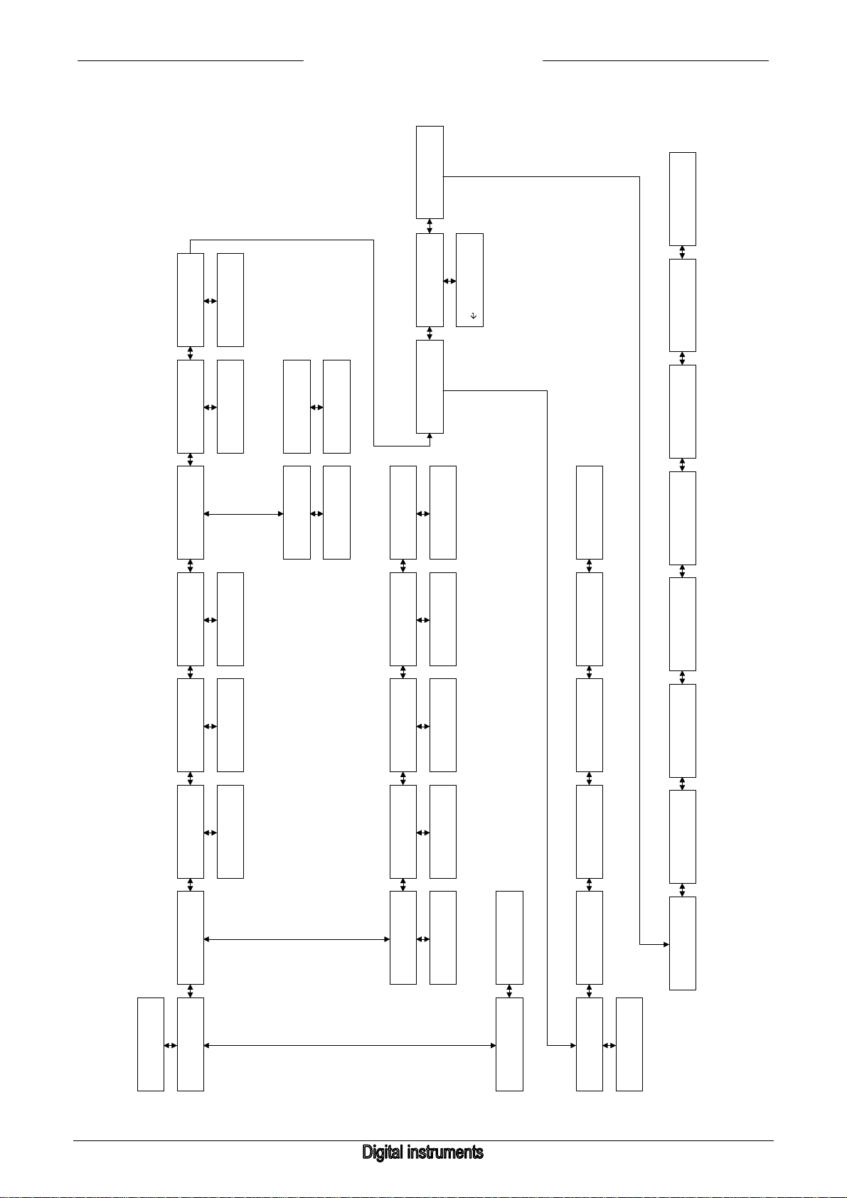
4.8 Instrument menu
(6800 0000)
INSTRUMENT MENU
SELECT FLUID(nr)
SELECT FLUID
NR: (nr)
(6700 0000)
INSTRUMENT MENU
REF. DENSITY (nr)
DENSITY (nr)(kg/m3):
x.xxxxx
(6810 0000)
(6710 0000)
BRONKHORST HIGH-TECH B.V.
(6B00 0000)
INSTRUMENT MENU
CONTROLLER
(6A00 0000)
INSTRUMENT MENU
RESTORE BACKUP
RESTORE SETTINGS
[ ] to restore
(6900 0000)
(6680 0000)
(6681 0000)
INSTRUMENT MENU
IDENTIFICATION
POLYNOMIAL
H1 x.xxxxxx
POLYNOMIAL CONST
H1: x.xxxxxx
(6A10 0000)
VALVE OUTPUT[V]
VALVE OPEN[V]
CONTR.CONST TD
(6B80 0000)
VALUE: XX.XX
(6B70 0000)
VALUE: XX.XX
(6B60 0000)
VALUE: X.XXXX
INSTRUMENT MENU
INSTRUMENT MENU
INSTRUMENT MENU
INSTRUMENT MENU
POLYNOMIAL (nr)
FLUID NAME (nr)
CAPACITY (nr),100%
CAPACITY 0%
(6600 0000)
(6500 0000)
(6400 0000)
(6300 0000)
FLUID NAME (nr):
xxxx
CAPACITY (nr),100%:
xxxxxx [unit]
CAPACITY 0%:
xxxxxx [unit]
(6510 0000)
(6410 0000)
(6310 0000)
POLYNOMIAL
A1 x.xxxxxx
(6610 0000)
POLYNOMIAL CONST
A1: x.xxxxxx
(6611 0000)
SENSOR:
SENSOR: FLOW
SENSOR: FLOW
SENSOR: FLOW
OTHER
GAS VOLUME(MASS)
LIQUID/GAS MASS
LIQUID VOLUME
(6250 0000)
(6240 0000)
(6230 0000)
(6220 0000)
0%, 100% measure
GAS VOLUME FLOW
LIQ/GAS MASSFLOW
LIQ VOLUME FLOW
and unit name
UNIT1: xxxx
UNIT1: xxxxx
UNIT1: xxxx
(6251 0000)
(6241 0000)
(6231 0000)
(6221 0000)
MFR. CONFIG.:
[xxxxxxxx]
VERSION:
VX.XX
MODEL NUMBER:
[xxxxxx]
DEVICE TYPE:
[xxxxxx]
(6860 0000)
(6850 0000)
(6840 0000)
(6830 0000)
CONTR.CONST Ti
CONTR.CONST Kp
CONTR.STABLE RESP
CONTR.NORM RESP
(6B50 0000)
VALUE: X.XXXX
(6B40 0000)
VALUE: X.XXXX
(6B30 0000)
VALUE: XXX
(6B20 0000)
VALUE: XXX
(6200 0000)
INSTRUMENT MENU
SENSOR TYPE
(6000 0000)
(6100 0000)
INSTRUMENT MENU
INSTRUMENT MENU
INSTRUMENT TYPE
(6210 0000)
(6211 0000)
SENSOR:
PRESSURE
PRESSURE
UNIT1: xxxx
INSTRUMENT TYPE:
INSTRUMENT TYPE:
CONTROLLER
METER
(6120 0000)
(6110 0000)
(6820 0000)
SERIAL NUMBER:
[xxxxxxxxxxxxxxxx]
(6810 0000)
USER TAG:
[xxxxxx]
USER TAG:
[xxxxxx] (edit)
(6811 0000)
(6B10 0000)
CONTR.OPEN RESP
VALUE: XXX
page 54 9.17.004

BRONKHORST HIGH-TECH B.V.
Menu descriptions
6100 0000 Instrument Type. Here you can change if the instrument will control or only measure mass flow or
pressure.
6110 0000 This will only let you measure the process. You can`t give setpoints.
6120 0000 This will let you control the process. You can edit the setpoint.
6200 0000 Sensor Type. Here you can select the used sensor type from the device.
This is mainly to obtain correctly direct reading in absolute values. Together with the capacity you
can define what 100% signal means. For example: sensortype ‘Gas volume’ gives readout units
like: ‘mln/min’, ‘ln/min’, ‘m3s/h’ etc.
After ‘UNIT’ the selected fluid number will be shown on the display.
6210 0000 Pressure sensor. This prepares module for readout in pressure units. In this mode the counter is
not available.
6211 0000 Select the pressure sensor readout unit with UP/DOWN key.
After unit selection choose: ‘a’ (absolute), ‘g’ (gauge), ‘d’ (differential) or ’. ‘ (no extension)
6220 0000 Liquid Volume Sensor. This prepares module for readout in liquid volume units.
6221 0000 Select the liquid volume readout unit with UP/DOWN key.
6230 0000 Liquid/Gas Mass Sensor. This prepares module for readout in mass flow units.
6231 0000 Select the liquid/mass flow sensor unit with UP/DOWN key.
6240 0000 Gas Volume Sensor. This prepares module for readout in gas volume (mass) units.
6241 0000 Select the gas volume readout unit with UP/DOWN key.
6250 0000 Other Sensor Type. This prepares module for readout in customized units. In this mode the
counter is not available, and you can not enter a capacity.
6251 0000 Here you can define your own sensor type. In order, you must enter the zero scale value (0%),
the full scale value (100%) and the unit type.
6300 0000 Sensor Capacity 0%. Here you can enter the capacity at 0%. This is the value which goes with
0% signal.
6310 0000 Edit the capacity at 0%.
6400 0000 Sensor Capacity. Here you can enter the sensor capacity. This is the value which goes with
100% signal at the selected readout unit.
6410 0000 Edit the sensor capacity.
6500 0000 Fluid Name. Here you can edit the fluid name (max. 10 characters).
6510 0000 Edit the fluid name.
6600 0000 Polynomial Constants. Here you can change the polynomial correction constants for this
instrument Normally these factors are obtained at calibration and represent a 3rd grade
polynomial function.
6610 0000 Here you can edit the polynomial constant A for selected fluidnr.
6611 0000 Edit constant A. (6520 to 6581 likewise for constants B...D or B…H, depending on the instrument
to be operate).
6700 0000 Here can you edit the density of the actual fluid.
6710 0000 Edit the actual density.
6800 0000 Fluidset Select. Here you can change the actual fluidset.
Your current settings will be saved and the settings of the selected fluidset will be the active
settings.
6810 0000 Select the active fluidset with UP/DOWN keys.
The fluidname will be displayed also (when filled-in).
6900 0000 Instrument Identification. Here you can change the User Tag and check the hard- and software
identification settings of the operated instrument
6910 0000 User Tag. Here you can view the user tag of the operated instrument.
6911 0000 User Tag. Here you can change the user tag.
6920 0000 Serial number. Here you can view the serial number of the operated instrument. The Bronkhorst
HIGH-TECH B.V. serial number is a unique identification for FLOW-BUS modules/ instruments.
6930 0000 Device Type. Here you can view as which type the operated instrument is configured.
6940 0000 Model Number. Here you can view the model number of the operated instrument.
6950 0000 Version. Here you can view the software version of the operated instrument.
6960 0000 Manufacturer Configuration. Here you can view the manufacture configuration of the operated
instrument.
9.17.004 page 55

BRONKHORST HIGH-TECH B.V.
6A00 0000 Restore Backup. This function restores the backup (the factory settings) which was made after
the final test in de factory.
6A10 0000 Press ‘enter’ to restore backup on instrument.
6B00 0000 Controller menu. This menu option is only available if the operating instrument is a controller.
6B10 0000 Here you can change the response factor of the control process when it should open the valve.
6B20 0000 Here you can change the response factor of the normal control process of setpoint steps.
6B30 0000 Here you can change the response factor of the control process when it is stable, difference
between setpoint and measured value <2%.
6B40 0000 Here you can change the Kp parameter of the PID controller.
6B50 0000 Here you can change the Ti parameter of the PID controller.
6B60 0000 Here you can change the Td parameter of the PID controller.
6B70 0000 Here you can view the valve open voltage.
6B80 0000 Here you can view the actual valve voltage.
page 56 9.17.004

BRONKHORST HIGH-TECH B.V.
9.17.004 page 57

4.9 Local menu
BRONKHORST HIGH-TECH B.V.
(7360 0000)
MFR. CONFIG.:
[xxxxxxxx]
(7350 0000)
VERSION:
VX.XX
LOCAL MENU
LOCAL MENU
TERMINAL MODE
RESTORE BACKUP
(7500 0000)
(7400 0000)
(7300 0000)
LOCAL MENU
LOCAL MENU
RESTORE BACKUP
MULTI CHANNEL
SINGLE CHANNEL
[ ] to restore
(7520 0000)
(7510 0000)
(7410 0000)
(7340 0000)
MODEL NUMBER:
[xxxxxx]
(7330 0000)
DEVICE TYPE:
[xxxxxx]
(7320 0000)
SERIAL NUMBER:
[xxxxxxxxxxxxxxxx]
(7310 0000)
(7311 0000)
READING MODE:
PERCENTAGE BAR
(7230 0000)
(7220 0000)
(7160 0000)
DISPLAY MODE:
LARGE SENSOR
(7150 0000)
DISPLAY MODE:
SENSOR BAR
(7140 0000)
DISPLAY MODE:
SETPOINT/SENSOR
(7130 0000)
LOCAL MENU
LOCAL MENU
(7000 0000)
LOCAL MENU
LOCAL MENU
IDENTIFICATION
(7200 0000)
READING MODE
(7100 0000)
DISPLAY MODE
USER TAG:
[xxxxxx]
EDIT USER TAG:
[xxxxxx] (edit)
READING MODE:
ACTUAL
(7210 0000)
READING MODE:
PERCENTAGE
DISPLAY MODE:
COUNTER/SENSOR
(7120 0000)
DISPLAY MODE:
TAG/FLUID/COUNTER
(7110 0000)
DISPLAY MODE:
TAG/FLUID/SENSOR
page 58 9.17.004

BRONKHORST HIGH-TECH B.V.
Menu descriptions
7100 0000 Display Mode.
Here you can change the values that will be displayed on the Readout Display.
7110 0000 This option will display the instrument user tag, the fluid name and the measured value in the
measure menu readout screen.
7120 0000 This option will display the instrument user tag, the fluid name and the counter value.
7130 0000 This option will display the counter value and the measured value
7140 0000 This option will display the setpoint and the measured value.
7150 0000 This option will display the measured value in a percentage bar from 0 to 100%.
7160 0000 This option will display the measured value with large characters.
7200 0000 Reading Mode. Here you can switch between direct/percentage reading.
7210 0000 Switch to percentage reading.
7220 0000 Switch to direct reading in absolute values. Absolute values can be selected at sensor type and
capacity of the instrument menu.
7230 0000 Switch to percentage bar reading.
7300 0000 Local Identification. Here you can change the User Tag and check the hard- and software
identification settings of this module.
7310 0000 User Tag. Here you can view the user tag of this module.
7311 0000 User Tag. Here you can change the user tag.
7320 0000 Serial number. Here you can view the serial number of this single channel module. The
Bronkhorst HIGH-TECH B.V. serial number is a unique identification for FLOW-BUS modules/
instruments.
7330 0000 Device Type. Here you can view as which type the device is configured.
7340 0000 Model Number. Here you can view the model number of the module.
7350 0000 Version. Here you can view the software version.
7360 0000 Manufacture Configuration. Here you can view the manufacture configuration.
NOTE: To activate the flowing menu options the password should be entered in RESET MENU
PASSWORD.
7400 0000 Restore backup. This function restores the backup (the factory settings) which was made after
the final test in de factory.
7410 0000 Press ‘enter’ to restore backup.
7500 0000 Select terminal mode. Here you can change the terminal mode.
7510 0000 Here you can select the single channel mode. This mode is preferred when only one instrument
is operated.
7520 0000 Here you can select the multi channel mode. This mode is preferred when often switching
between different instruments is required.
9.17.004 page 59

FLOWBUS SETTINGS
4.10 FLOW-BUS menu
BRONKHORST HIGH-TECH B.V.
FLOW-BUS MENU
FLOW-BUS MENU
CHECK MY SETTING
OPERATE INSTR.
(8400 0000)
SETTINGS PNA:xxx
(8300 0000)
(8200 0000)
LNA:xxx NNA:xxx
(8410 0000)
(8210 0000)
NEW ADDRESS: xxx
(8210 0000)
(8411 0000)
(8320 0000)
OPERATE INSTR.
CHECK SETTINGS
(8310 0000)
OPERATE INSTR.
SEARCH INSTR.
(8321 0000)
INSTR. PNA:xxx
LNA:xxx NNA:xxx
Search instr.
Node: xxx Proc:xx
INSTR. FB. SET.
(8311 0000)
(8311 0000)
INSTR.: xxxxx
xxxxxxxxxxxxxxxx
NEW ADDRESS: xxx
(8321 1000)
FLOW-BUS MODE:
STOP COMMUNIC.
FLOW-BUS MODE:
START COMMUNIC.
(8140 0000)
(8130 0000)
(8120 0000)
INSTALL INSTR.:
NEW ADDRESS : xxx
FLOW-BUS MENU
FLOW-BUS MENU
(8000 0000)
FLOW-BUS MENU
INSTALL INSTR.
(8100 0000)
INSTALL MYSELF
INSTALL INSTR.:
xxxxxxxxxxxx
FLOW-BUS MODE:
REMOTE INSTALL
(8110 0000)
FLOW-BUS MODE:
AUTO INSTALL
page 60 9.17.004

BRONKHORST HIGH-TECH B.V.
Menu descriptions
8100 0000 Install myself.
Here you can install this module on the FLOW-BUS and start/stop the communication.
8110 0000 Auto install.
Press 'enter' to install this module on the FLOW-BUS. It will search for a free adress on the bus
by itself and install there.
8120 0000 Remote Install.
Press 'enter' to let this module get into INIT mode so it can be installed to the bus by an external
device (operation module or PC). You have one minute now to perform the installation
procedure.
8130 0000 Start Communication.
When you press 'enter' in this menu communication with the bus will be (re)started (use after
stopping communication temporarily). When the device is properly installed, it will start
communication at power-up and after a reset automatically.
8140 0000 Stop Communication.
When you press 'enter' in this menu communication with the bus will be stopped until ‘Start
communication' will be selected or at a reset of the module.
8200 0000 Install instrument. Here you can remote install a module which has been set in remote install
mode.
8210 0000 The module which has been set in remote install mode is shown. After pressing ‘enter’ you can
select an address on which the module should be installed. If an address is selected, press
‘enter’ again and the module will be installed on this address.
NOTE:
To avoid FLOW-BUS communication problems it is recommended to install new instruments to
the advised address.
8300 0000 Operate instrument. Here you can search an operating instrument or view and change the
FLOW-BUS settings of the operating instrument.
8310 0000 Search instrument. Here you can search an instrument to be operated.
8311 0000 Use ‘left’ and ‘right’ keys to search an instrument on the FLOW-BUS. Confirm with 'enter'.
8320 0000 Check settings. Here you view FLOW-BUS settings of the instrument you want to operate.
8321 0000 Here you can view the PNA and NNA of the operated instrument.
8321 1000 Here you can change the PNA of the operated instrument.
8400 0000 Check My Settings. Here you check FLOW-BUS settings of this module.
8410 0000 PNA means Primary (own) Node Address of module on the FLOW-BUS.
NNA means Next Node Address. This address points to the next module on the FLOW-BUS and
will be changed automatically if a new module is add to the FLOW-BUS behind this module. If
the module is the last module on the FLOW-BUS, its NNA points to zero.
LNA means Last Node Address. The next node on the bus should have an address below LNA.
8411 0000 Here you can change the PNA of the module. If you give a new address, the module will restart
the communication. The NNA is default set to PNA+1. During communication NNA values may
change automatically because FLOW-BUS optimises it self for optimum communication speed.
NOTE 1:
Normally installation on the FLOW-BUS has to be performed only one time. Mostly this will be done at
Bronkhorst High-Tech B.V. when your module has been built and tested. The address on the bus for this
module will be stored when the module powers-off. At future power-on situations, it will be part of the FLOWBUS on the same address each time. However, there can be situations you have to install your module on
the bus again. For example:
1) When you want to rebuild your FLOW-BUS system.
2) When you want to add this module to another FLOW-BUS system.
3) When, at the check at start-up, the module finds out that its address to be on the FLOW-BUS is
occupied already by another module. You will get a message on your display That you have to reinstall the module on the bus.
9.17.004 page 61

BRONKHORST HIGH-TECH B.V.
NOTE 2:
Make sure this module has been switched-off before connecting it to the FLOW-BUS.
First make FLOW-BUS connection, then switch-on the power. Only in this order the module is able to
perform its communication checkings properly.
In case of the hand held version the module is powered by the FLOW-BUS. The module will automatically
switch-on when it is connected to the FLOW-BUS.
How to install the E-7000 modules on the FLOW-BUS network, see manual 9.17.024.
page 62 9.17.004

BRONKHORST HIGH-TECH B.V.
4.11 Calibration with polynomial functions
4.11.1 General information
A normally calibrated device will have a linearized transfer function. This means that real flow/pressure and
setpoint are proportional to the output signal.
A polynomial function is a method of approximation which mathematically describes a continues transfer
function.
By means of a few samples, a polynomial function can be obtained.
After determining the polynomial function, the original calibration points and an infinite amount of values in
between, can be calculated with high accuracy.
In a system where pressure- and/or flow meters and -controllers should be readout and set with high
accuracy, these polynomial functions often are used for approximation of their transfer function. For instance
the function which describes the relation between output signal and measured flow.
4.11.2 General form
The general form of a polynomial function of the n-nd degree is as follows:
Y = a0 + a1 · X + a2 · X
Where 'a0' to 'an' are polynomial parameters, which can be calculated.
When you have 'n + 1' measure-points, they can be approximated by means of a 'n-nd' degree polynomial
function.
4.11.3 Polynomial functions of sensor signal and setpoint
By means of a calibration at Bronkhorst High-Tech B.V. several measure points will be used to obtain a
polynomial function.
The form of this function is:
Y = a + b · X + c · X
In which 'Y' is the measured value and 'X' is the value of output signal.
Characters 'a - d' are polynomial parameters, which can be obtained by a mathematical program. These
parameters can be filled in and the polynomial function is completed.
2
+ a3 · X3 + ……+ an · Xn
2
+ d · X3
4.11.4 Presentation of parameters
Parameters 'a - d' are polynomial function parameters, which can be obtained with a mathematical program
out of measured calibration points.
All parameters will be presented in scientific notation with 5 significant digits, where the last digit is obtained
by rounding-off.
Example (unscaled):
a = -2.1899 E-03
b = +9.7442 E-01
c = +8.9309 E-02
d = -5.9906 E-02
Polynomial function for sensor signal:
Y = -2.1899 · 10
-3
+ 9.7442 · 10-1 · X + 8.9309 · 10-2 · X2 - 5.9906 · 10-2 · X3
9.17.004 page 63

BRONKHORST HIGH-TECH B.V.
4.11.5 Using polynomial functions at readout/control unit
The parameters for the polynomial functions are stored in the digital instrument and can be changed from the
keyboard.
Normally the transfer function is linear Y = X.
The connected device will have linearized transfer functions after (normal) calibration.
The accuracy however, will be ≤ 1 % full scale.
When a special polynomial function calibration is wanted, the parameters 'a-d' will be destillated and factory
stored in the digital instrument. In the 'INSTRUMENT'-menu you have access to these values.
page 64 9.17.004

BRONKHORST HIGH-TECH B.V.
5 MAINTENANCE
- Be sure you operate under the correct input specifications.
- Be sure the system operates within its temperature range.
- When replacing a defective fuse, first solve the problem.
- Only install a fuse with the correct current rating (see label).
- Only clean the housing (keyboard and display) with a (moist) polishing cloth. Do not use aggressive
cleaning fluids.
9.17.004 page 65

BRONKHORST HIGH-TECH B.V.
6 TROUBLESHOOTING
• LCD is not lit after 'power on' • check power input
• check fuse
• Improper reading • check module settings
• No reading/control • check instrument cabling
• Improper system operation (alarm, counter) • check module settings
• Instrument does not respond to setpoint given at
keyboard
• Setpoint menu cannot be reached • check setting of connected instrument type at
• Counter/alarm is not responding to reset • check if reset-source has been enabled at reset
• Instrument seems to give inaccurate values • check if correct fluid set (with calibration factors)
• Display shows ‘---‘ • check if the operating instrument is active
• Other problems • check instrument and operating module
• setpoint source at operation menu should enable
setpoint at "keyb. & FLOW-BUS". (other settings
means different behaviour)
• setpoint could have been overruled at an alarm
situation or counter limit (first perform reset)
• setpoint slope has a large value. (setpoint will
slowly change in time) Change slope value if
necessary.
• setpoint could be changed by other devices
connected to the FLOW-BUS.
• check polynomial factors for setpoint and
measure at instrument menu.
• check communication with FLOW-BUS.
If applicable
instrument menu. For sensor types setpoint
facilities will be disabled.
menu of reset counter/alarm.
has been selected (see fluidname).
• check if the operating instrument is still at the
same address.
• check instrument and module cabling
parameters.
page 66 9.17.004
 Loading...