

Broaster 1800 SERVICE MANUAL
SERVICE MANUAL
BROASTER® 1600 AND 1800
PRESSURE FRYER
Be sure ALL installers read, understand, and have access to this manual at all times.
Genuine Broaster Chicken®, Broasted®, Broaster Chicken®, Broaster Foods®. and Broasterie® are registered
trademarks. Usage is available only to licensed operators with written authorization from The Broaster Company.
2855 Cranston Road, Beloit, WI 53511-3991
Design Certified By:
1600: CSA, NSF and UL
1800: CSA (AGA & CGA), NSF and UL
Broaster Company
608/365-0193 broaster.com
Manual #14680 3/99 Rev. 1/17
© 1999 Broaster Company
Printed In U.S.A.

All adjustments and repairs shall be made
FOR YOUR SAFETY
Do not use or store gasoline or other flammable vapors
or liquids in the vicinity of this or any other appliance.
Improper installation, adjustments, alteration, service or maintenance can cause
property damage, injury or death. Read the installation, operating and maintenance instructions thoroughly before installing or servicing this equipment.
For the sake of safety and clarity, the following words used in this manual are defined as follows:
Indicates an imminently hazardous situation which, if not avoided, could
result in serious injury or death.
Indicates a potentially hazardous situation which, if not avoided, could
result in serious injury or death.
Indicates a potentially hazardous situation which, if not avoided, could
result in minor injury, property damage or both.
by an authorized Broaster Company representative.
when the cook/filter switch is moved to
If at any time the POWER
ON light does not turn off
the OFF position, disconnect the power
If there is a power failure, turn cook/filter
switch OFF. On the Model 2400GH, also
slide switch on gas valve OFF. DO NOT
to the fryer and contact your local
Broaster Company representative for
service immediately.
attempt to operate unit during a power failure.
DO NOT operate unit
without filter pan and filter
Failure to read and
understand this manual
completely could result in serious injury
pan cover in its proper position. Filter
pan cover must be wiped clean after
each filtering cycle.
or death. Be sure ALL operators read,
understand and have access to this
manual at all times.
Rags or paper containing
ports on bottom of cover are clear of any
oil or grease buildup.
Make sure Pressure Relief
Valve and Pressure Gauge
cooking oil can catch fire
if exposed to heat. Laundering will not
remove the oil. Dispose of all oil-soiled
papers and rags in a trash container that
is in a ventilated area away from all
cooking equipment or other heat
sources such as direct sunlight.
1600 Mechanical Controls:
If at any time the unit fails
to operate properly when
the cook/filter switch is moved to the
cook position, contact your local
Broaster Company representative for
service immediately.
cont’d on next page
W-1
broaster.com Manual #14680 3/99 Rev: 10/15

1600/1800E Solid State Controls:
If at any time the POWER
ON light does not turn off
when the cook/filter switch is moved to
the OFF position, disconnect power to
the fryer and contact your local Broaster
Company representative for service
immediately.
1800GH:
Post, in prominent locations, instructions to
be followed in the event that the user smells
gas. This information can be obtained from
your local gas supplier.
Make sure a restraining
device is used that
complies with the Standard for
Commercial Gas Ranges, ANSI Z83.11/
CSA 1.8 to guard against transmission of
strain to the gas connectors.
Failure to restrain the
fryer could allow it to
move, causing hot shortening to spill
out, or a possible break in the gas line
causing an explosive condition.
broaster.com Manual #14680 3/99 Rev: 10/15
W-2

TABLE OF CONTENTS
1 - WARNING SIGNS AND LABELS ................................................................................... 1 - 1
1600 DOMESTIC AND CE ............................................................................................ 1 - 1
1600 FRENCH CANADIAN ........................................................................................... 1 - 2
1800 DOMESTIC AND CE ............................................................................................ 1 - 3
1800 FRENCH CANADIAN ........................................................................................... 1 - 4
2 - ELECTRIC POWER SUPPLY ......................................................................................... 2 - 1
WIRING DIAGRAMS
Single and Three Phase Power Connection ............................................................ 2 - 1
DOMESTIC:
1600 Mechanical ................................................................................................ 2 - 2
1600/1800E Solid State ..................................................................................... 2 - 6
1800GH ............................................................................................................ 2 - 10
EXPORT:
1600XP/1800EXP Mechanical.......................................................................... 2 - 11
1600XP/1800EXP Solid State .......................................................................... 2 - 15
1800GHXP........................................................................................................ 2 - 18
EU:
1600CE Mechanical ......................................................................................... 2 - 19
1600CE/1800ECE Solid State.......................................................................... 2 - 20
1800GHCE ....................................................................................................... 2 - 21
United Kingdom:
1600UK/1800EUK ............................................................................................ 2 - 22
1800GHUK ....................................................................................................... 2 - 23
480V Units:
1800E 480V Δ ........................................................................................... 2 - 24
1600XP 240/480V ............................................................................................ 2 - 25
1800XP 480V.................................................................................................... 2 - 27
3 - 1600 MECHANICAL CONTROL PANEL ........................................................................ 3 - 1
FAMILIARIZATION......................................................................................................... 3 - 1
ACCESS FOR SERVICE................................................................................................ 3 - 2
INDICATOR LIGHTS...................................................................................................... 3 - 3
COOK/FILTER SWITCH AND POWER ON SWITCH..................................................... 3 - 3
TIMER ...........................................................................................................................3 - 4
HI-LIMIT ........................................................................................................................3 - 5
THERMOSTAT............................................................................................................... 3 - 6
broaster.com Manual #14680 399 Rev 5/14
i

4 - SOLID STATE CONTROL PANEL .................................................................................. 4 - 1
ROTARY DIAL FAMILIARIZATION ................................................................................. 4 - 1
CONTROLLER PROGRAMMING ............................................................................ 4 - 2
CALIBRATION ......................................................................................................... 4 - 3
DUAL DISPLAY FAMILIARIZATION............................................................................... 4 - 4
CONTROLLER PROGRAMMING ............................................................................ 4 - 5
WARNING DISPLAYS .............................................................................................. 4 - 6
DISPLAYING ACTUAL TEMPERATURE .................................................................. 4 - 6
CALIBRATION.......................................................................................................... 4 - 6
TEMP-N-TIME FAMILIARIZATION ................................................................................ 4 - 7
CONTROLLER PROGRAMMING ............................................................................ 4 - 8
PRESET COOK MODE ............................................................................................ 4 - 9
PROGRAMMING METHOD 1 ............................................................................ 4 - 9
PROGRAMMING METHOD 2 .......................................................................... 4 - 10
WARNING DISPLAYS ............................................................................................ 4 - 10
DISPLAYING ACTUAL TEMPERATURE ................................................................ 4 - 11
CALIBRATION........................................................................................................
4 - 11
ACCESS FOR SERVICE.............................................................................................. 4 - 12
COOK/FILTER SWITCH .............................................................................................. 4 - 13
HI-LIMIT CONTROL .................................................................................................... 4 - 13
POWER ON INDICATOR LIGHT.................................................................................. 4 - 15
SOLID STATE CONTROLLER ..................................................................................... 4 - 15
TEMPERATURE SENSOR PROBE.............................................................................. 4 - 16
5 - POWER INPUT BOX....................................................................................................... 5 - 1
1600/1800E
CONTACTORS (1600/1800E) .................................................................................. 5 - 2
FUSE (1600/1800E) ................................................................................................. 5 - 3
HEATING ELEMENTS (1600/1800E)........................................................................ 5 - 3
LIMIT SWITCH......................................................................................................... 5 - 5
RELAY (1600/1800E) ............................................................................................... 5 - 6
1800GH
TRANSFORMER (1800GH)...................................................................................... 5 - 7
1800GHCE
IGNITION CONTROL ............................................................................................... 5 - 8
1800GHUK
iGNITIO
N CONTROL ............................................................................................... 5 - 9
TRANSFORMER.................................................................................................... 5 - 10
RELAYS ................................................................................................................. 5 - 10
6 - COVER AND YOKE ........................................................................................................ 6 - 1
PROPER COVER OPERATION ..................................................................................... 6 - 1
FAMILIARIZATION......................................................................................................... 6 - 2
ADJUSTMENTS ............................................................................................................ 6 - 3
REMOVAL ..................................................................................................................... 6 - 4
DISASSEMBLY.............................................................................................................. 6 - 4
ASSEMBLY ................................................................................................................... 6 - 5
PRESSURE GAUGE...................................................................................................... 6 - 6
SAFETY RELIEF VALVE................................................................................................. 6 - 7
broaster.com Manual #14680 399 Rev 6/16
ii

8 - 1800 PRESSURE SYSTEM ............................................................................................ 8 - 1
EXHAUST DRAIN TUBE................................................................................................ 8 - 2
EXHAUST TANK ............................................................................................................ 8 - 2
EXHAUST TUBE............................................................................................................ 8 - 3
PRESSURE REGULATING VALVE................................................................................. 8 - 3
9 - 1800GH MAIN BURNER SYSTEM................................................................................. 9 - 1
MODEL 1800GH LIGHTING INSTRUCTIONS .............................................................. 9 - 1
GAS CONVERSION ...................................................................................................... 9 - 1
HIGH ALTITUDE ............................................................................................................ 9 - 1
VENTILATION ................................................................................................................ 9 - 2
GAS VALVE ................................................................................................................... 9 - 2
FLAME ADJUSTMENTS ............................................................................................... 9 - 3
AIR SHUTTER ............................................................................................................... 9 - 5
COMBUSTION CHAMBER ........................................................................................... 9 - 5
MAIN BURNER ORIFICE...............................................................................................
9 - 7
PILOT BURNER ORIFICE ............................................................................................. 9 - 8
10 - DRAIN VALVE AND FILTER SYSTEM........................................................................ 10 - 1
DRAIN VALVE.............................................................................................................. 10 - 1
FILTER PAN................................................................................................................. 10 - 2
CHECK VALVE ............................................................................................................ 10 - 3
MOTOR ....................................................................................................................... 10 - 4
PUMP.......................................................................................................................... 10 - 6
11 - TROUBLESHOOTING ................................................................................................ 11 - 1
ELECTRICAL TIPS ...................................................................................................... 11 - 1
SOLIDE STATE CONTROLLER TIPS .......................................................................... 11 - 2
SMART TOUCH CONTROLLER TIPS ........................................................................ 11 - 3
GAS TIPS (1800GH) .................................................................................................... 11 - 4
COVER AND YOKE TIPS ............................................................................................ 11 - 4
PRESSURE SYSTEM TIPS ......................................................................................... 11 - 5
PRODUCT TIPS .......................................................................................................... 11 - 6
FRESH CHICKEN ............................................................................................... 11 - 6
FROZEN IQF CHICKEN ..................................................................................... 11 - 6
FILTERING TIPS .......................................................................................................... 11 - 8
FLOW CHART - 1600 & 1800E ................................................................................. 11 - 10
FLOW CHART - 1800GH .......................................................................................... 11 - 12
broaster.com Manual #14680 399 Rev 3/16
iii

1 - WARNING SIGNS
CAUTION
When servicing a Broaster
® Pressure Fryer,
be sure all safety devices and warning signs
are in place and legible. If not, The Broaster
Company should be notified in writing of
the lack of warning signs and the existence
of an unsafe condition.
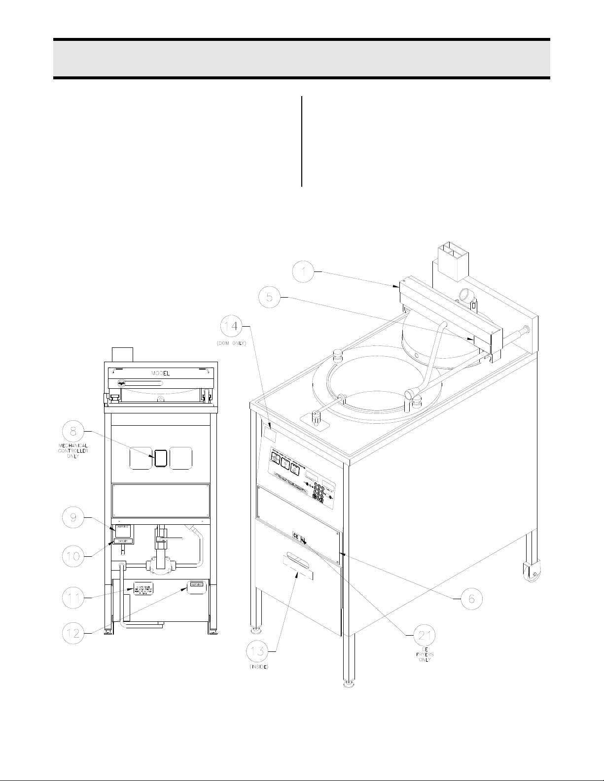
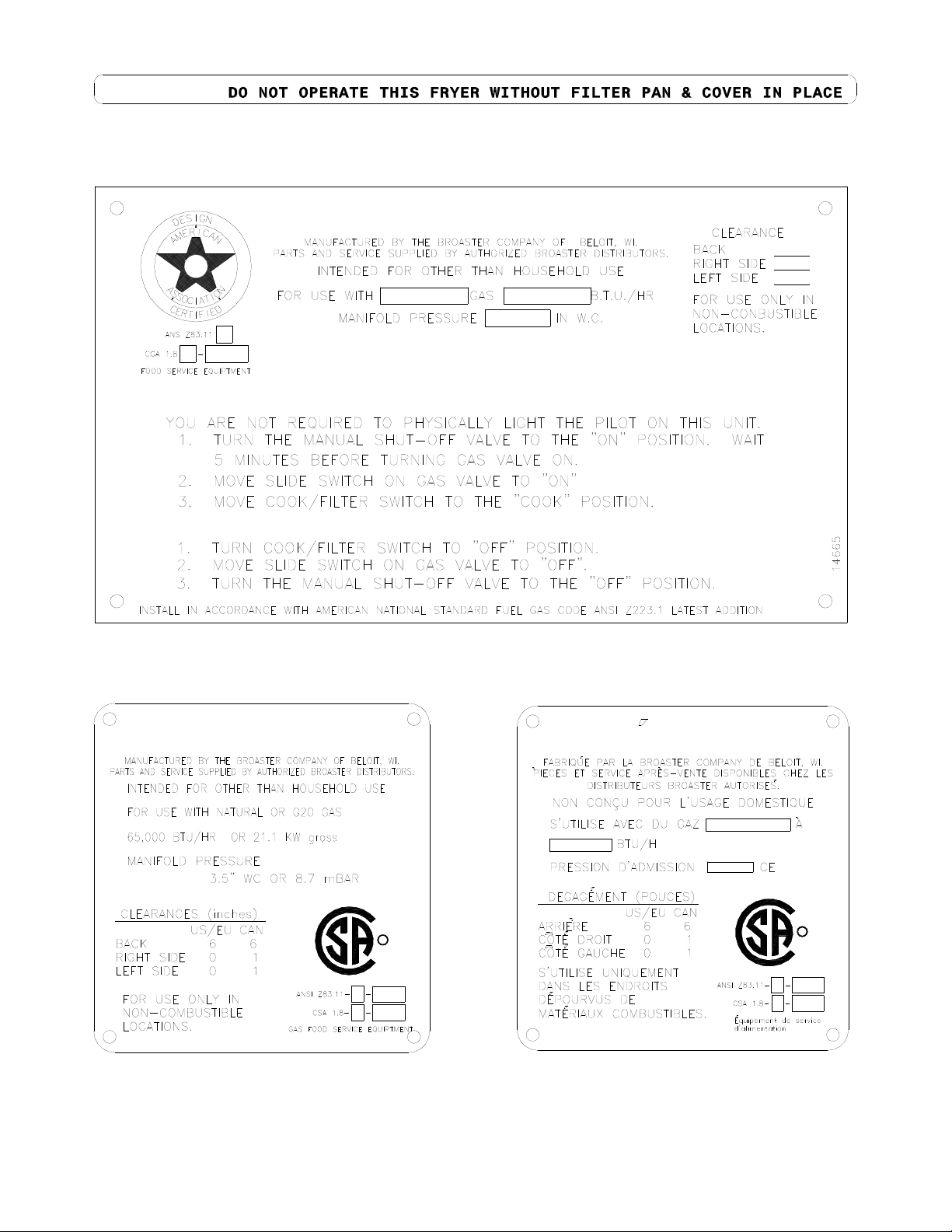
1600 Domestic and CE Labeling
If you need replacement warning signs or
manuals, contact an authorized Broaster
Company representative or The Broaster
Company Service Department at 608/365-
0193.
broaster.com Manual #14680 3/99 Rev 5/14
1-1
1600 French Canadian Labeling
CAUTION
broaster.com Manual #14680 3/99 Rev 5/14
1-2
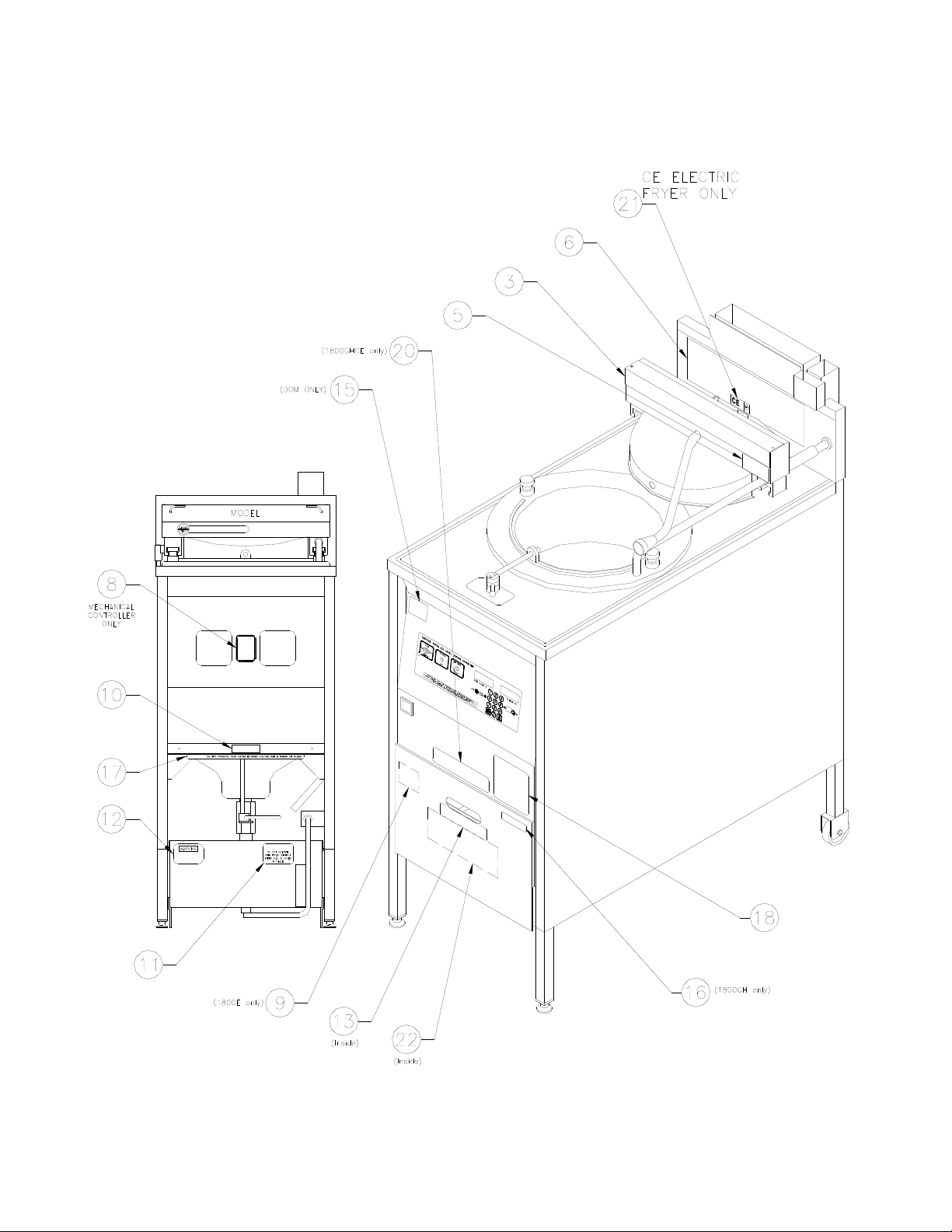
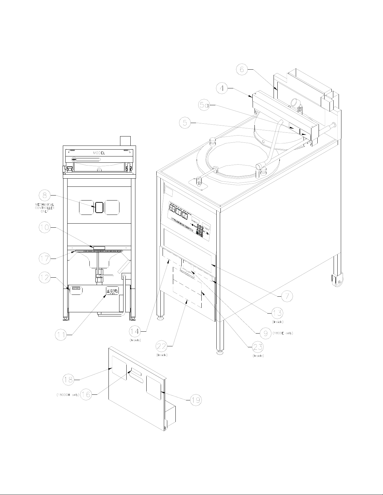
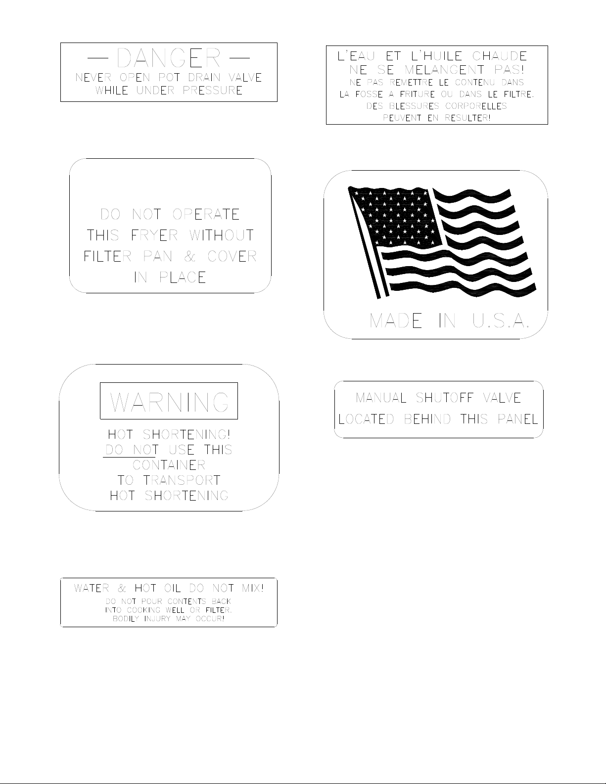
1800 Domestic and CE Labeling
CAUTION:
CAUTION
1-3
broaster.com Manual #14680 3/99 Rev 5/14
1800 French Canadian Labeling
CAUTION:
CAUTION
1-4
broaster.com Manual #14680 3/99 Rev 5/14

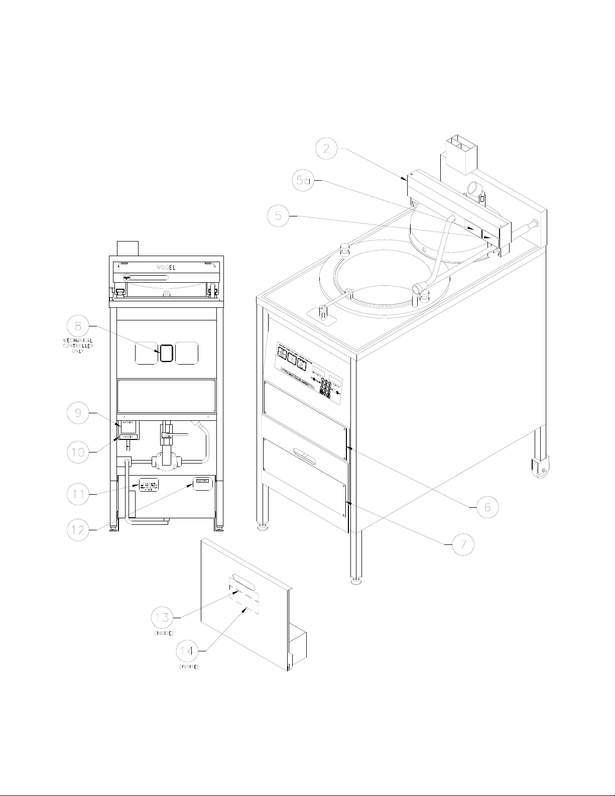
Item 1 - Part #10733
Item 2 - Part #10959
Item 3 - Part #10886
Item 4 - Part #10957
Item 5- Part #16368
Item 5a- Part #17064
1-5
broaster.com Manual #14680 3/99 Rev 5/14
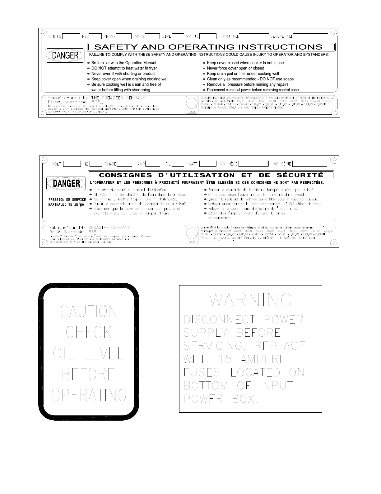
MADE IN U.S.A.
MAXIMUM WORKING
PRESSURE 15 P.S.I.
NSF
Item 6 - Part #11027
FABRIQUE AUX E.-U.
NSF
2
Item 7 - Part #15223
Item 8 - Part #14463
Item 9 - Part #11073
1-6
broaster.com Manual #14680 3/99 Rev 5/14
Item 10 - Part #06375
CAUTION
Item 11 - Part #15725
Item 14 - Part #13761
Item 15 - Part #15398 Domestic Only
Item 12 - Part #11028
Item 13 - Part #10900
Item 16 - Part #11746 (1800GH Only)
1-7
broaster.com Manual #14680 3/99 Rev 5/14
MODEL 1800GH
OPERATING INSTRUCTIONS
SHUT DOWN
START UP
G
A
S
CAUTION:
Item 17 - Part #15785
MODEL 1800GH
CUS
R
CUS
R
MODELE 1800GH
Item 17 - Part #14665 (1800GH Only)
Item 18a (1800GH after July 2003)
#15777 for Nat Gas
#16993 for LP Gas
Item 19 - Part #14730
1-8
broaster.com Manual #14680 3/99 Rev 5/14
I
I
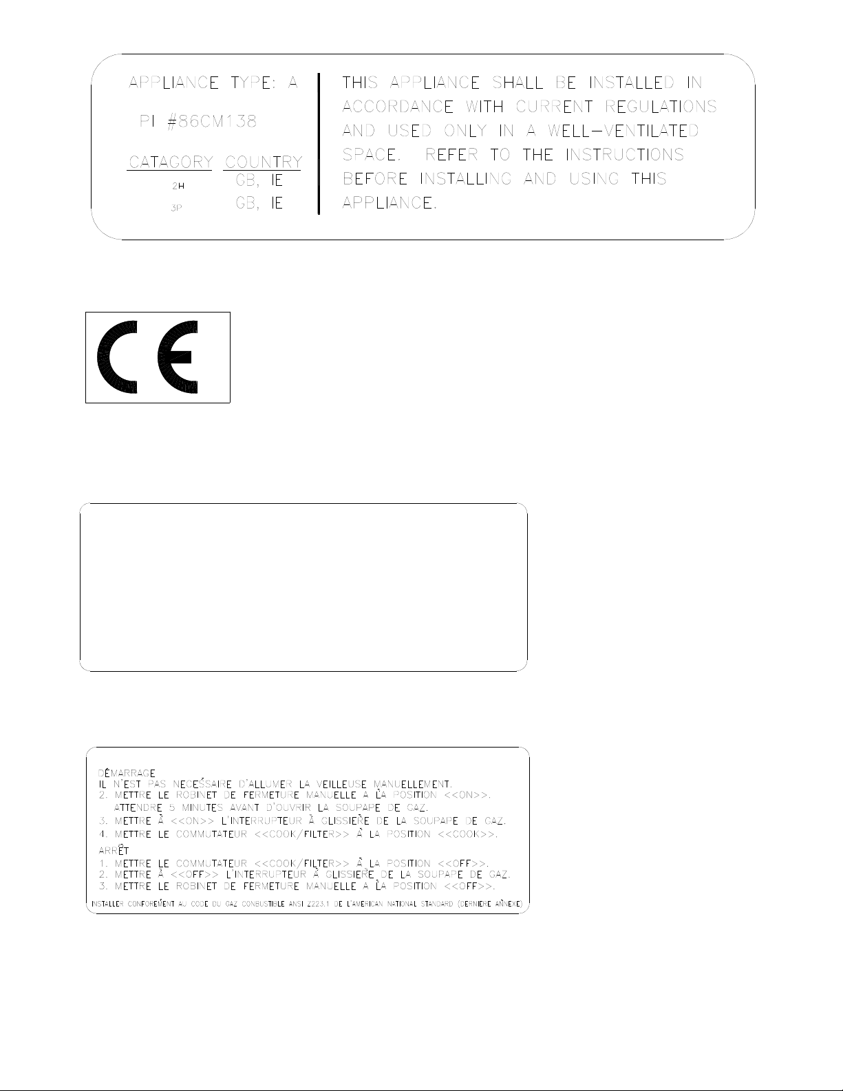
Item 20 - Part #15846 (1800GHCE only)
OPERATING INSTRUCTIONS
START UP
YOU ARE NOT REQURIED TO PHYSICALLY LIGHT THE PILOT ON THIS UNIT.
1. TURN THE MANUAL SHUT-OFF VALVE TO THE "ON" POSITION. WAIT
5 MINUTES BEFORE TURNING GAS VALVE ON.
2. MOVE SLIDE SWITCH ON GAS VALVE TO "ON"
3. MOVE COOK / FILTER SWITCH TO THE "COOK" POSITION.
SHUT DOWN
1. TURN COOK / FILTER SWITCH TO "OFF" POSITION.
2. MOVE SLIDE SWITCH ON GAS VALVE TO "OFF".
3. TURN THE MANUAL SHUT-OFF VALVE TO THE "OFF" POSITION.
INSTALL IN ACCORDANCE WITH AMERICAN NATIONAL STANDARD FUEL GAS CODE ANSI Z223. 1 LATEST ADDITION
MODE D'EMPLOI
Item 21
CE Electric fryers - Part #13739
CE Gas fryers - Part #16349
Item 22 - Part #15694 Domestic
Part #15795 CE
Item 23 - Part #16994
1-9
broaster.com Manual #14680 3/99 Rev 5/14

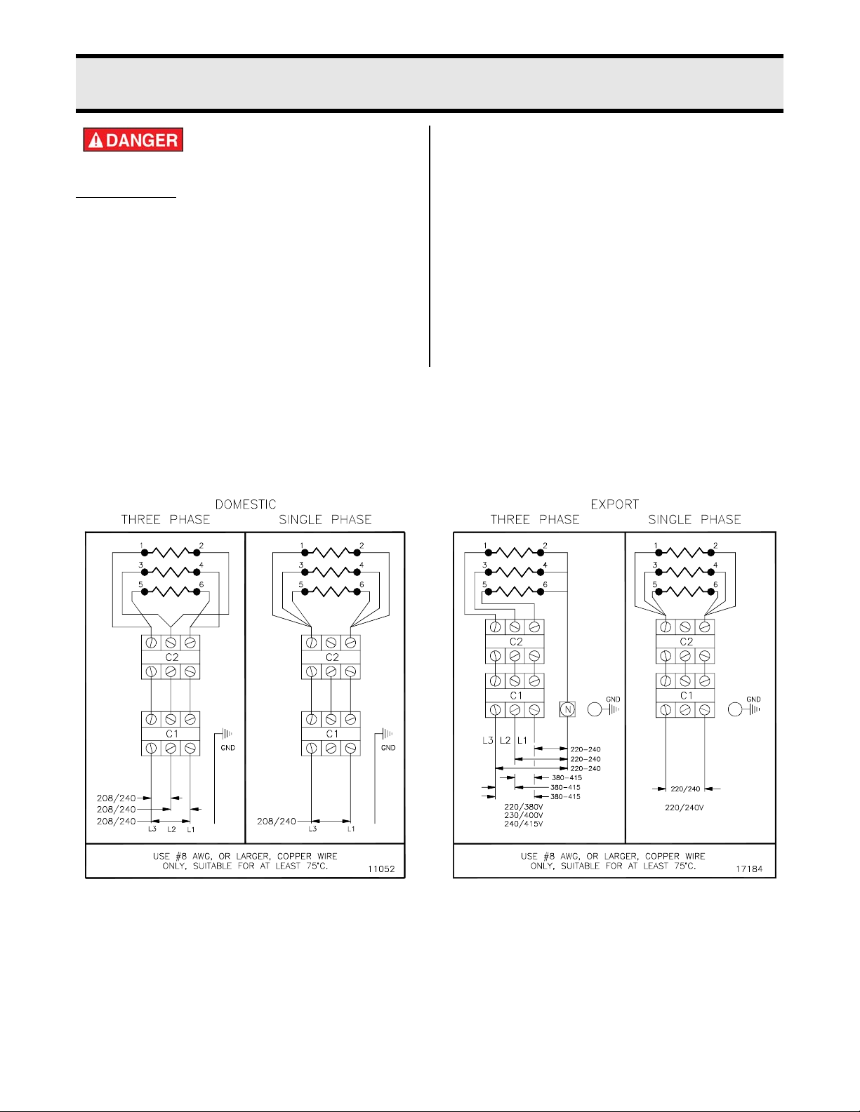
2 - ELECTRIC POWER SUPPLY
3Ph 50/60Hz
1Ph. 50/60Hz
Many sections in this
manual pertain to checking and repairing electrical components.
High voltage
will be encountered in several instances. Only persons trained and
equipped for checking high voltage shall
undertake such repairs.
If no component operates, check main
power supply. Be sure main circuit breaker
is ON and main fuses are good.
Correct voltage will be either 208 or 240V.
WIRING DIAGRAMS
Three and Single Phase Wiring Connections:
Perform the following if unit will not turn on:
1. Disconnect main power supply.
2. Be sure all connections are tight. If
power supply is proper, see TROUBLESHOOTING section.
Wiring diagrams are located on inside front
panel.
2-1
broaster.com Manual #14680 3/99 Rev 5/14

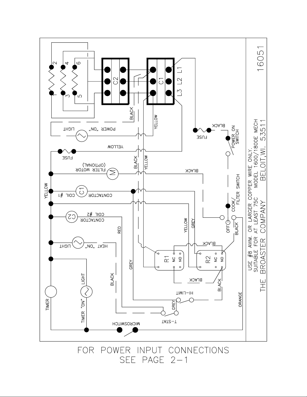
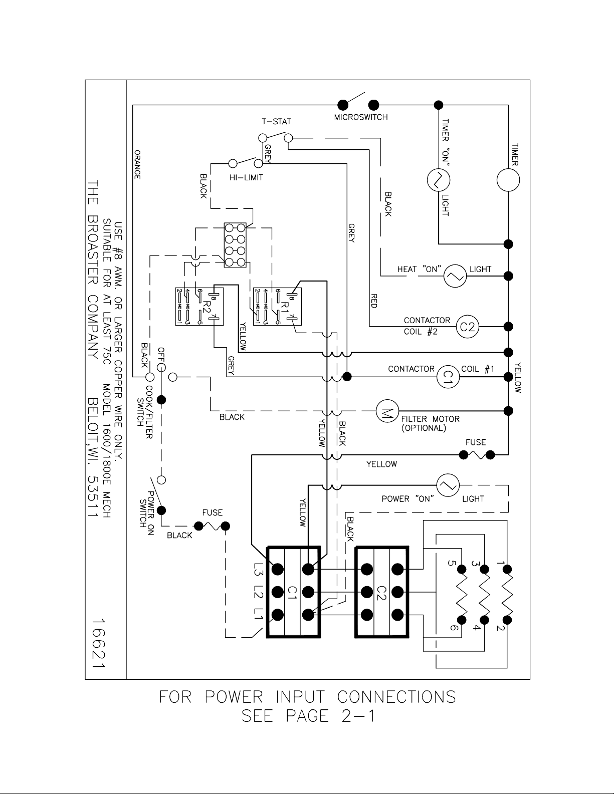
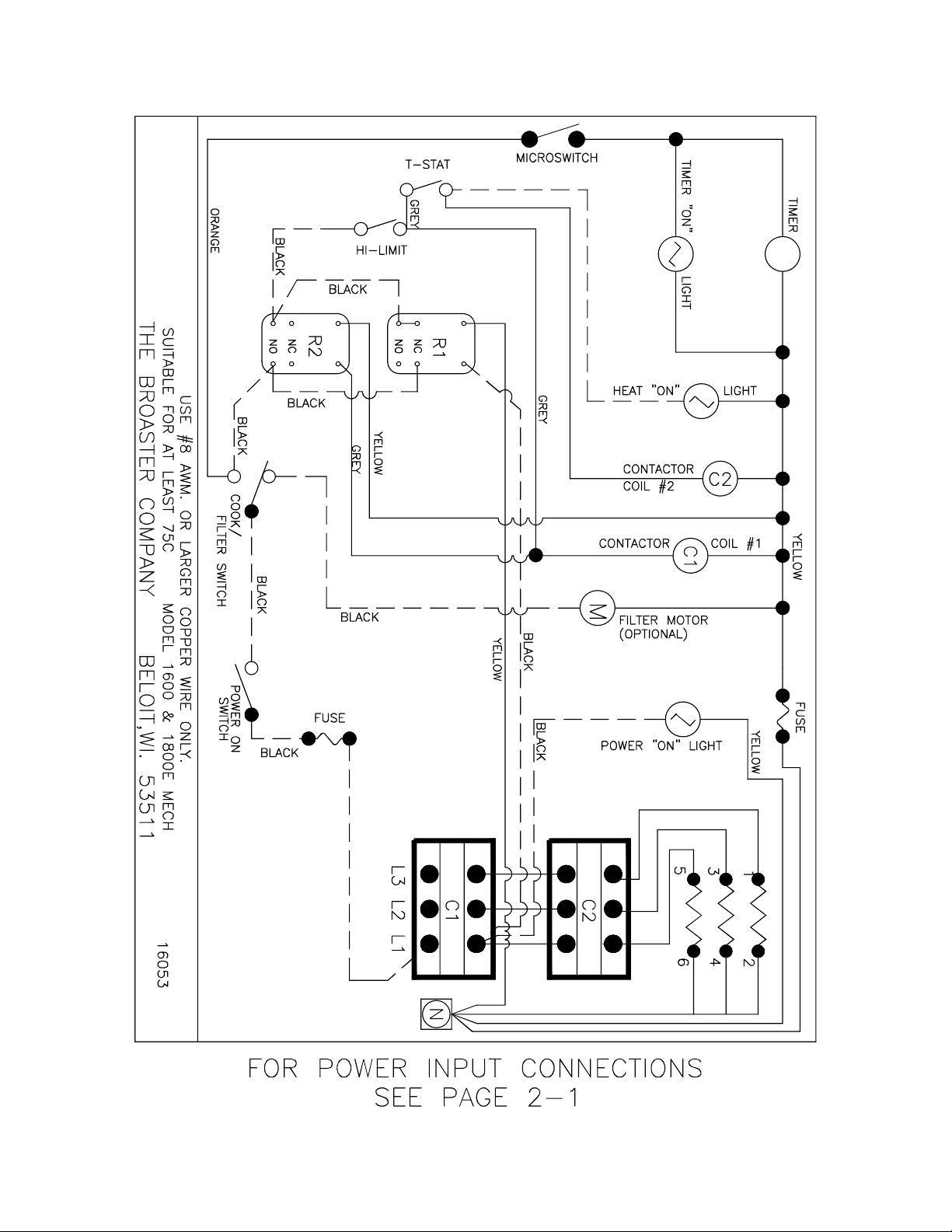
1600 Mechanical 208 or 240VAC:
broaster.com Manual #14680 3/99 Rev 5/14
2-2
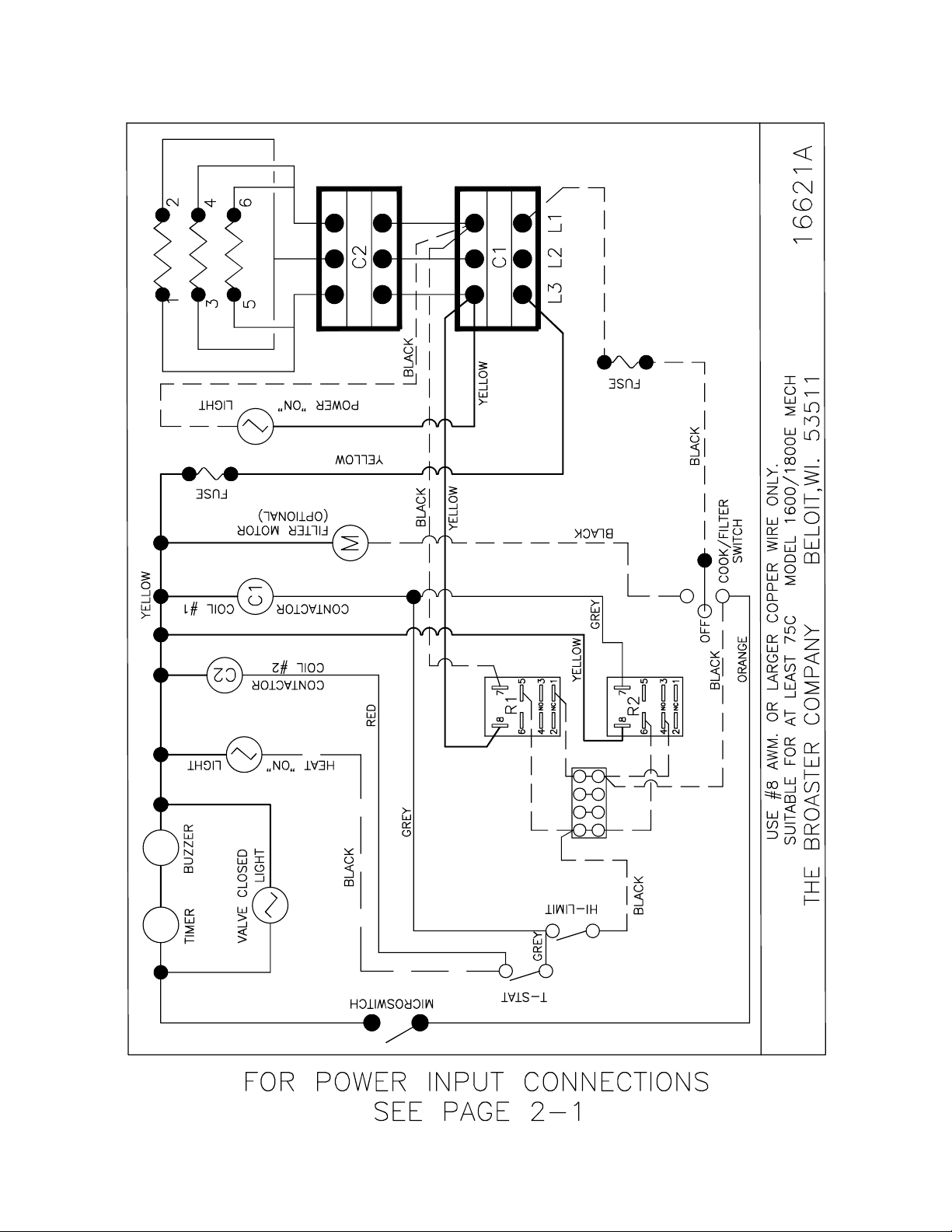
1600 Mechanical 208 or 240VAC: Effective E16E401073
1
3
5
2
6
4
1
3
5
2
4
6
E18C401133
2-3
broaster.com Manual #14680 3/99 Rev 5/14
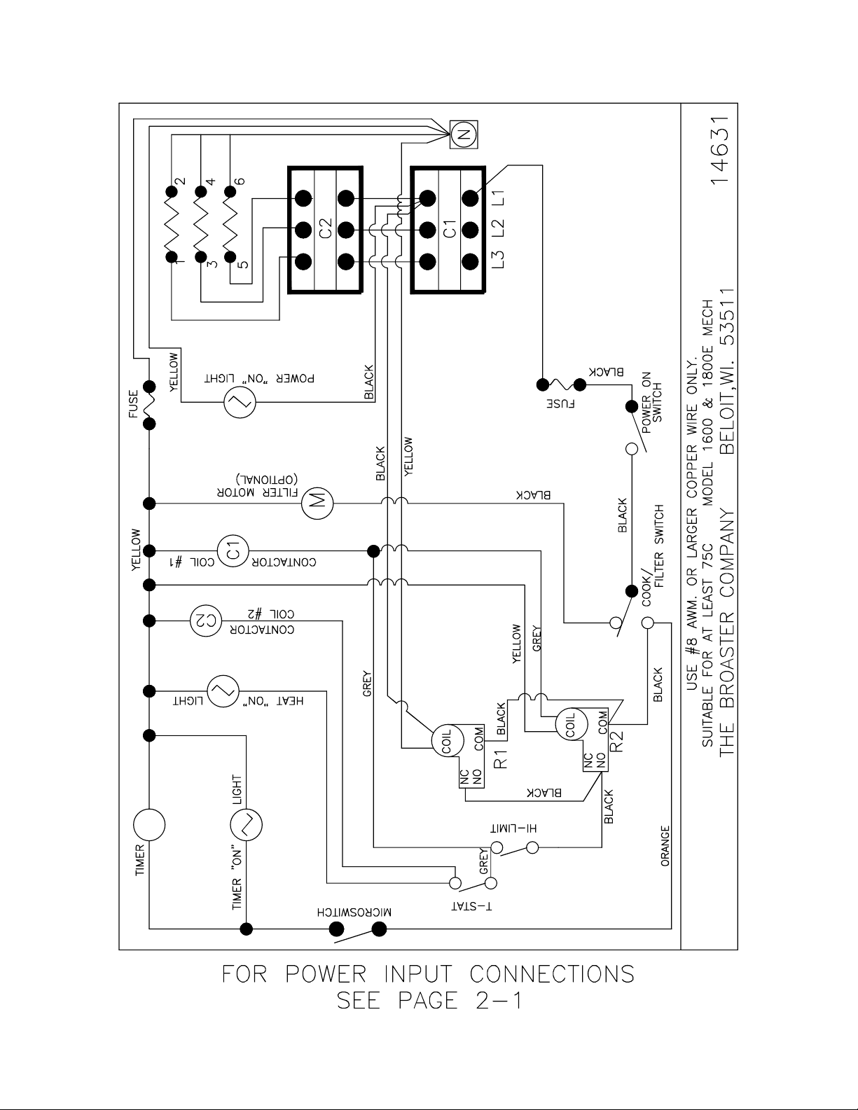
1600 Mechanical 208 or 240VAC: Effective E16A700023
E18A700043
broaster.com Manual #14680 3/99 Rev 5/14
2-4
1600 Mechanical 208 or 240VAC: Effective E16L700000
E18K700000
broaster.com Manual #14680 3/99 Rev 5/14
2-5
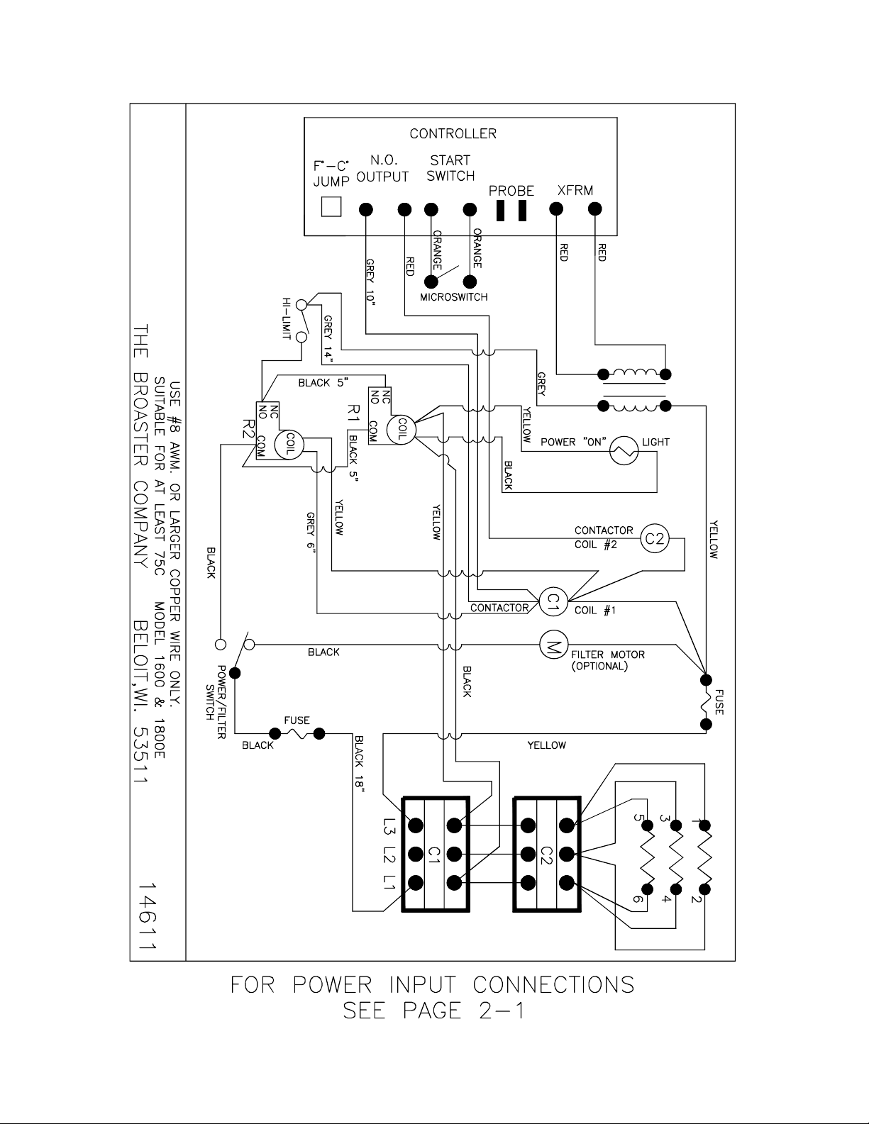
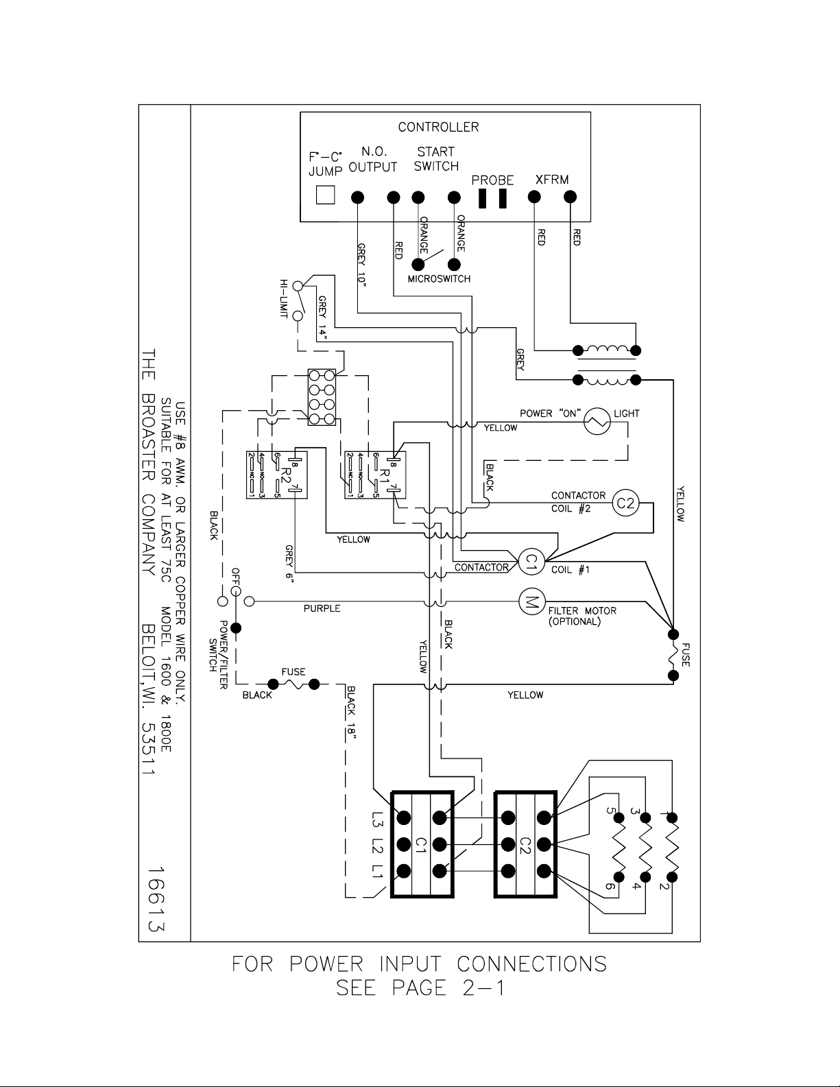
1600/1800E Solid State 208 or 240VAC:
broaster.com Manual #14680 3/99 Rev 5/14
2-6
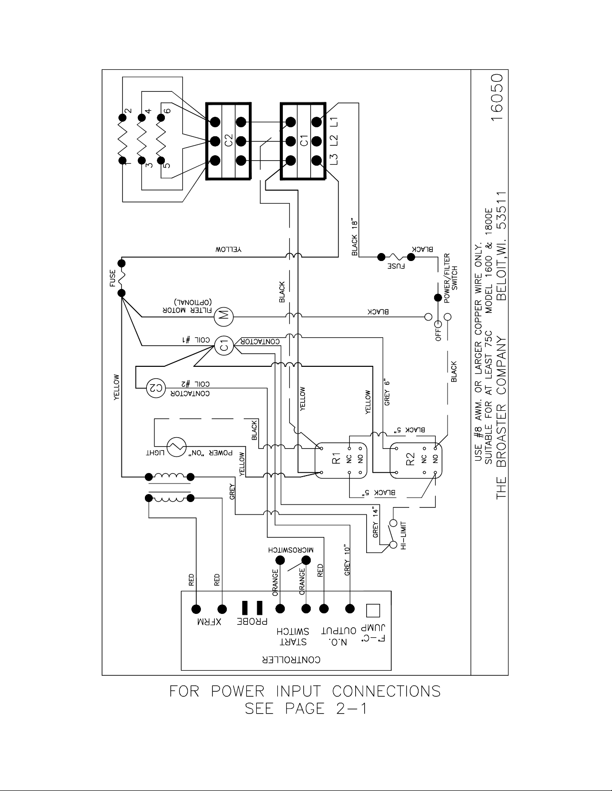
1600/1800E Solid State 208 or 240VAC: Effective SE6E401073
5
6
5
6
1
3
24
1
3
2
4
2-7
broaster.com Manual #14680 3/99 Rev 5/14
1600/1800E Solid State 208 or 240VAC: Effective SE6A700013
SE8A700011
broaster.com Manual #14680 3/99 Rev 5/14
2-8
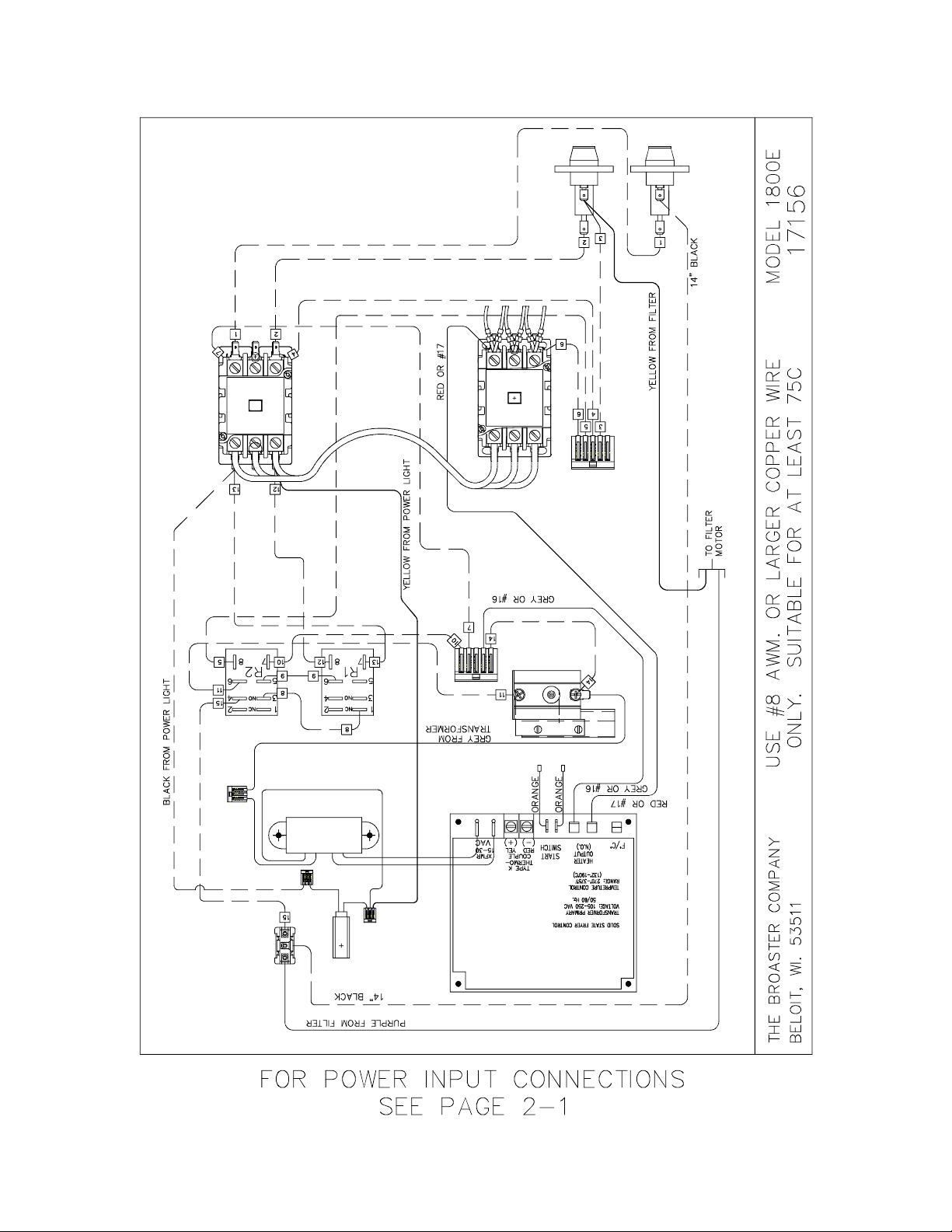
1600/1800E Solid State 208 or 240VAC: Effective - SE8A213193
2
5
1
346
broaster.com Manual #14680 3/99 Rev 5/14
2-9
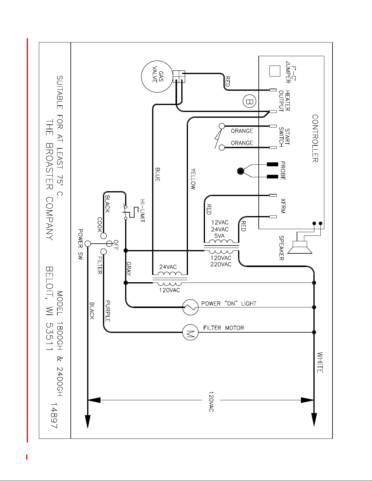
1800GH Solid State:
broaster.com Manual #14680 3/99 Rev 1/17
2-10
EXPORT: 1600XP/1800EXP Mechanical:
broaster.com Manual #14680 3/99 Rev 5/14
2-11
EXPORT: 1600XP/1800EXP Mchanical: Effective E16E401073
2
4
1
3
6
5
3
1
4
6
5
2
E18D401133
broaster.com Manual #14680 3/99 Rev 5/14
2-12
 Loading...