

Page 1

“An American Tradition Since 1954!”
MODEL V208-24 and V240-24
V24 VERTICAL ROTISSERIE
INSTALLATION/OPERATION MANUAL
Be sure ALL installers read, understand, and have access to this manual at all times.
Broaster®, Broasted®, Broasted Chicken®, Broaster Foods®. and Broasterie® are registered trademarks.
Usage is available only to licensed operators with written authorization from The Broaster Comany.
Bro-Tisserie Foods Division of The Broaster Company
2855 Cranston Road, Beloit, WI 53511-3991
608/365-0193 www.broaster.com
Design Certified by: NSF, UL, and CUL
Printed in USA Copyright 1997 The Broaster Company
13210 3/97 Rev 5/08
Page 2

Page 3

FOR YOUR SAFETY
Do not use or store gasoline or other flammable vapors
or liquids in the vicinity of this or any other appliance.
WARNING: Improper installation, adjustments, alteration, service or maintenance can
cause property damage, injury or death. Read the installation, operating and maintenance instructions thoroughly before installing or servicing this equipment.
For the sake of safety and clarity, the following words used in this manual are defined as follows:
DANGER: Indicates an imminently hazardous situation which, if not avoided, could result
in serious injury or death.
WARNING: Indicates a potentially hazardous situation which, if not avoided, could result
in serious injury or death.
CAUTION: Indicates a potentially hazardous situation which, if not avoided, could result in
minor injury, property damage or both.
All adjustments and repairs shall be made
by an authorized Broaster Company representative.
If there is a power failure, turn power switch
OFF. DO NOT attempt to operate unit during a power failure.
WARNING: Failure to read and
understand this manual completely
could result in serious injury or death. Be
sure ALL operators read, understand and
have access to this manual at all times.
WARNING: Rags or papers containing
cooking oil can catch fire if exposed to
heat. Laundering will not remove the oil. Dispose of all oil-soiled papers and rags in a trash
container that is in a ventilated area away from
all cooking equipment or other heat sources
such as direct sunlight.
Manual #13210 3/97 Rev: 3/06
Page 4

Page 5

TABLE OF CONTENTS
1 - LIMITED WARRANTY...................................................................................................1 - 1
2 - OWNER’S RESPONSIBILITY .......................................................................................2 - 1
3 - INSTALLATION..............................................................................................................3 - 1
LEVELING...................................................................................................................3 - 1
Without Base.......................................................................................................3 - 1
With Base............................................................................................................3 - 1
WIRING DIAGRAMS
Domestic .............................................................................................................3 - 2
Export..................................................................................................................3 - 6
4 - ROTISSERIE OPERATION............................................................................................4 - 1
CONTROL PANEL ......................................................................................................4 - 1
Familiarization.....................................................................................................4 - 1
Main Menu...........................................................................................................4 - 1
CONTROL PANEL Effective: V24B790013.................................................................4 - 2
Familiarization.....................................................................................................4 - 2
Main Menu...........................................................................................................4 - 2
CONTROLLER PROGRAMMING...............................................................................4 - 3
Products #1 - #10................................................................................................4 - 3
Standby 000F ......................................................................................................4 - 3
OPERATION AND PREPARATION...........................................................................4 - 4a
Whole Chicken....................................................................................................4 - 5
Preparation..........................................................................................................4 - 6
Starting A Cook Cycle .......................................................................................4 - 7a
CLEANING................................................................................................................4 - 7a
5 - CONVECTION OPERATION .........................................................................................5 - 1
DUCT VARIATIONS ....................................................................................................5 - 1
Air Circulation System #1....................................................................................5 - 1
Air Circulation System #2....................................................................................5 - 2
PROGRAMMING.........................................................................................................5 - 3
Products #1 - #10................................................................................................5 - 3
Standby 000F ......................................................................................................5 - 4
Manual 000F .......................................................................................................5 - 4
OPERATION..............................................................................................................5 - 5a
Starting A Cook Cycle .......................................................................................5 - 5a
CLEANING................................................................................................................5 - 6a
Manual #13210 3/97 Rev 12/05
Page 6

6 - RECIPES........................................................................................................................6 - 1
BEEF AND PORK .......................................................................................................6 - 1
Baby Back Pork Ribs...........................................................................................6 - 1
Fresh Top (Inside) or Bottom Round................................................................... 6 - 2
Fresh Prime Rib ..................................................................................................6 - 3
Fresh Pork Loin................................................................................................... 6 - 4
Fresh Boston Butt Pork Roast.............................................................................6 - 5
VEGETABLES.............................................................................................................6 - 6
Fresh Potatoes....................................................................................................6 - 6
BREADS......................................................................................................................6 - 7
Fresh Biscuits......................................................................................................6 - 7
Muffins (1 to 1 1/4 oz.).........................................................................................6 - 8
Muffins (1 1/2 to 2 oz.).........................................................................................6 - 9
Muffins (3 3/4 to 4 oz.).......................................................................................6 - 10
DESSERTS...............................................................................................................6 - 11
Frozen Cookies.................................................................................................6 - 11
Frozen Fruit Pie.................................................................................................6 - 12
Frozen Custard Pie ...........................................................................................6 - 13
MISCELLANEOUS....................................................................................................6 - 14
Frozen 20 oz. 12 Inch Pizza..............................................................................6 - 14
Fresh Turkey.....................................................................................................6 - 15
Manual #13210 3/97
Page 7

1 - LIMITED WARRANTY
Subject to the terms and conditions of this warranty, The Broaster Company (Company) warrants that all equipment and parts manufactured or sold by the Company and purchased new
from an authorized Company distributor are free from defects in material and workmanship for a
period of one year from the date of installation, if installation is made by a qualified installer
under supervision by an authorized distributor in accordance with applicable laws and regulations. Warranty coverage is extended to the original purchaser only and is void if the equipment
is resold. If an authorized Company distributor is notified of a warranty claim during the warranty period, the Company will at its option replace, recondition or repair at its factory any part
or parts of the equipment which the Company judges defective, provided the equipment has
been subjected to normal usage, properly installed, operated and serviced in accordance with
Company operating instructions, and there is no evidence of accident, alteration or abuse of the
equipment or the use of unauthorized repair methods. All parts replaced under this warranty
carry only the unexpired term of the warranty.
Service under this warranty shall be furnished only by an authorized Company distributor. The
Company does not send service representatives to furnish warranty service. Your authorized
Company distributor should be contacted for warranty service.
This warranty covers parts only and does not cover labor charges, transportation charges or
other expenses in the connection with warranty service, which are the obligation of the owner
unless otherwise specified in the original sales contract between the purchaser and the authorized Company distributor from which the equipment is purchased. Please refer to that contract
for coverage as to those charges.
This warranty does not apply to consumable items and supplies such as bulbs and lamps.
The foregoing warranty is made in lieu of all other warranties, express or implied, and
the Company specifically disclaims any implied warranties of merchantability or fitness
for a particular purpose. The Company’s full obligation under this warranty, and the pur-
chaser’s sole remedy shall be limited to replacement, reconditioning or repair as specified
above.
IN NO EVENT SHALL THE COMPANY BE LIABLE TO THE ORIGINAL OWNER OR ANY
OTHER PERSON FOR ANY INCIDENTAL, CONSEQUENTIAL OR SPECIAL DAMAGES
RESULTING FROM THE USE OR INABILITY TO USE THE EQUIPMENT COVERED
HEREBY, WHETHER ARISING FROM BREACH OF WARRANTY, STRICT LIABILITY OR
OTHERWISE.
The Company reserves the right to change or improve its products in any way without obligation
to alter products previously manufactured.
Used Company equipment or Company equipment not purchased from an authorized Company
distributor carries no warranty express or implied.
Manual #13210 3/97 1 - 1
Page 8

Page 9

2 - OWNER’S RESPONSIBILITY
It is the owner’s responsibility to:
• Insure the unit is properly maintained.
• Insure all safety devices and warning
signs are in their original location and
are legible.
• Allow only properly trained personnel to
operate, clean and maintain your unit.
• Insure main power supply is disconnected before the unit is serviced.
When you sell, trade or give away your unit,
you must make sure that all safety devices
are intact, warning signs are legible and the
Installation/Operation Manual is included
with the unit.
If you need replacement warning signs or
manuals, contact an authorized Broaster
Company representative or The Broaster
Company at 608/365-0193.
The Customer Service Department at The
Broaster Company should be contacted at
the time of sale or disposal of your unit so
records may be updated.
Manual #13210 3/97 2 - 1
Page 10

Page 11

3 - INSTALLATION
1. Install machine with minimum 3 inches
clearance on sides and back
2. A remote circuit breaker or fuse should
be installed in main power supply
located in a path of exit and clearly
identified.
3. All electrical work must conform to the
requirements of national, state, and
local electrical codes.
4. DO NOT apply a voltage to this unit
other than shown on dataplate. If in
doubt, consult your local power company.
5. The V24 is shipped 208 or 240 volts,
50/60 cycle, 9900 watts, with 3 phase
wiring and is field convertible to single
phase. Ratings are:
Phase Volts Amps Wire Fuse
Breaker
LEVELING
Leveling is important for proper door alignment.
Without Base:
1. Level unit front to back and side to side
by adjusting feet.
With Base:
Base with adjustable feet:
1. See Without Base above.
Base with casters:
Casters are not adjustable for the purpose
of leveling.
1. Be sure unit is installed on a level floor .
If necessary, add additional blocking
on a sloping floor.
1 208 48 #6 60
1 240 45 #6 60
3 208 28 #8 35
3 240 26 #8 35
1*220*51#6 70
3*220*29#8 40
* Indicate export electrical characteristics.
6. Exhaust hood, if needed, should comply with national, state, and local
codes.
2. Lock casters when leveling is complete.
3 - 1
Manual #13210 3/97 rev 4/03
Page 12

WIRING DIAGRAMS
V24 208/240V:
3 - 2
Manual #13210 3/97
Page 13

V24 208/240V
Effective: V24B790013
3 - 3
Manual #13210 3/97
Page 14

V24 208/240V
Effective: V24C40
1
3
1
3
65
5
6
24
42
3 - 4
Manual #13210 5/05
Page 15

V24 208/240V
Effective: V24A60
42
24
6
3
5
1
65
3
1
3 - 5
Manual #13210 12/05
Page 16
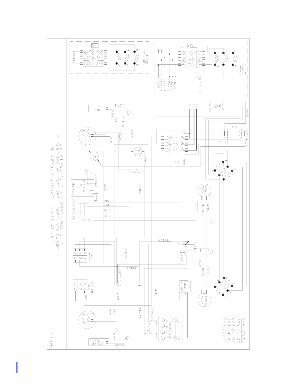
V24 Export:
3 - 6
Manual #13210 3/97 Rev 12/05
Page 17
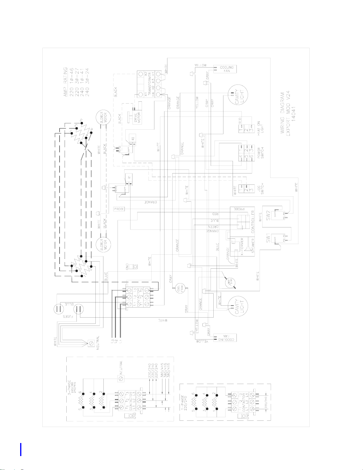
V24 Export
Effective: V24B790013
3 - 7
Manual #13210 3/97 Rev 12/05
Page 18
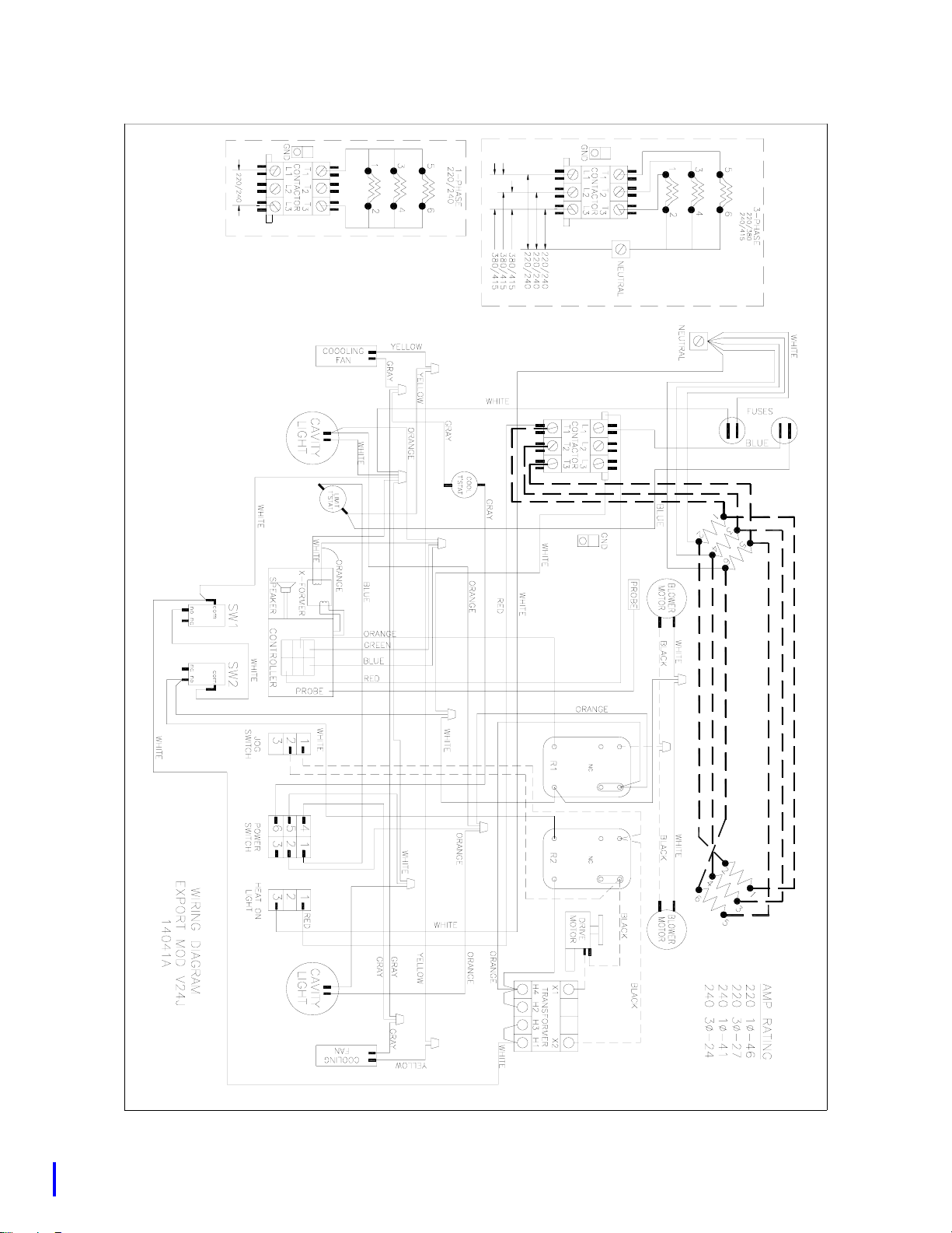
V24 Export
Effective: V24C40
3 - 8
Manual #13210 5/05 Rev 12/05
1
5
2
3
1
3
4
6
5
2
4
6
Page 19
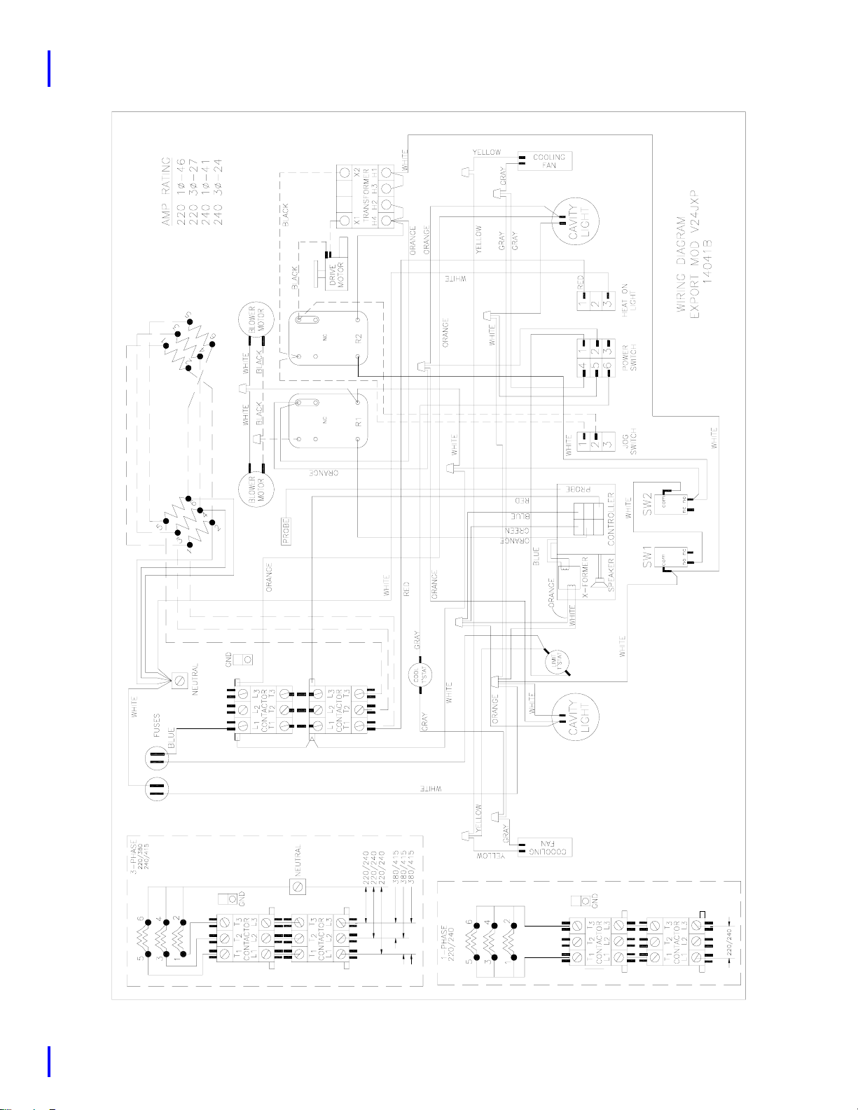
V24 Export
Effective: V24A60
6
4
2
4
2
3
5
1
6
3
5
1
3 - 9
Manual #13210 12/05
Page 20

Page 21
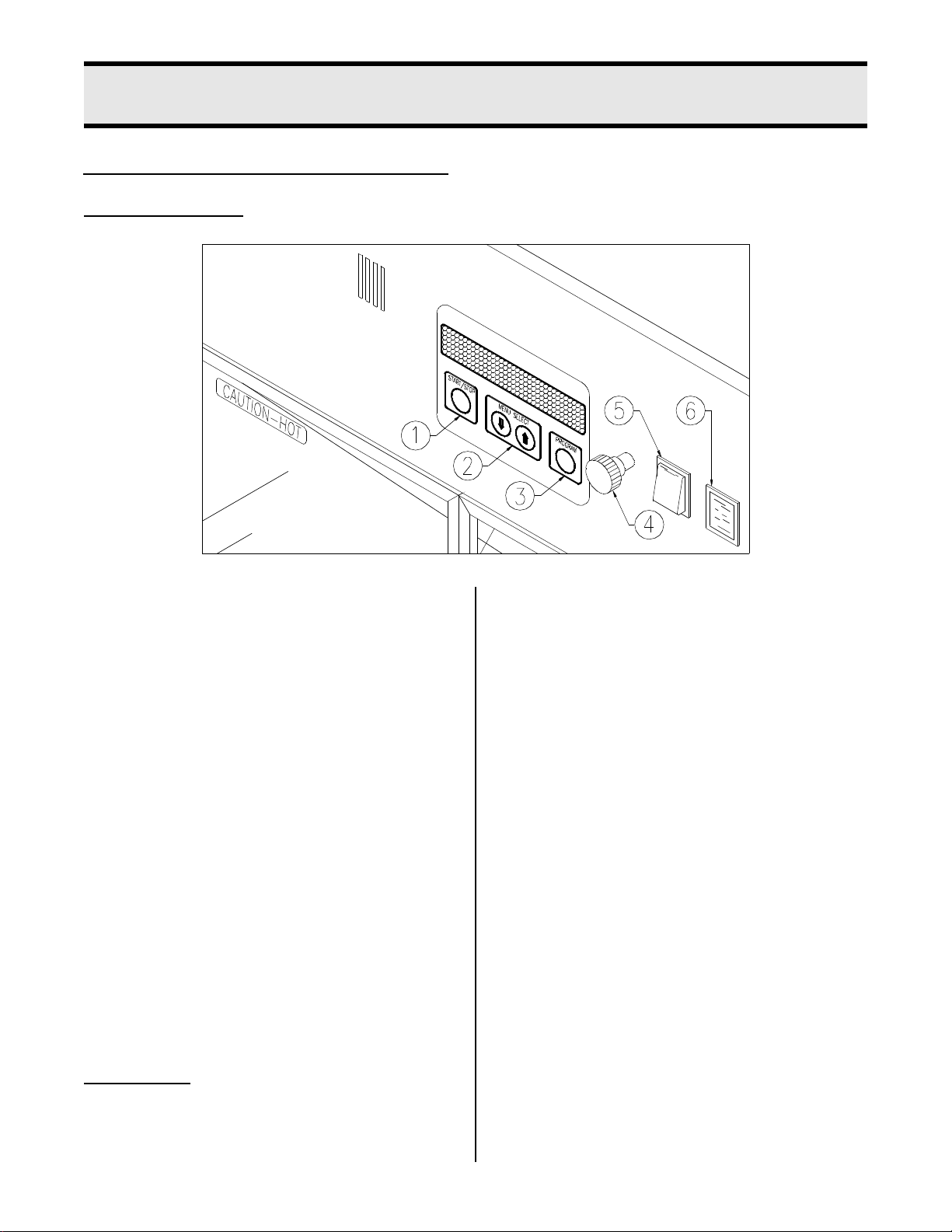
CONTROL PANEL
FAMILIARIZATION:
4 - ROTISSERIE OPERATION
1. Start/Stop Button: Press to start or
stop a cook cycle. To stop a cook cycle
or hold mode, press and hold for several seconds.
2. Menu Select buttons: Used to select
desired programmable choices and to
change program values.
3. Program Button: Used to enter and
exit programming mode.
4. Gear Drive Release: Pull to allow free
rotation of spit arm when loading and
unloading product when unit is ON.
5. Power Switch: This switch has two
positions: On and OFF.
6. Heat On Light: Illuminates when interior is being heated.
MAIN MENU:
• 000F = Cook temperature in degrees
Fahrenheit.
• 00:00:00 = Cook time in hours:minutes:seconds.
• #1 CK, #2 CK, etc. = Specific product to
be programmed.
Turn power switch ON. Display alternates
between LOW TEMP and STANDBY 000F.
Press the UP or DOWN buttons to select
desired main menu item:
• STANDBY 000F: Maintains a lower interior temperature during non-peak hours.
• #1 CK = 000F 00:00:00
• #2 CK = 000F 00:00:00
• #3 CK = 000F 00:00:00
• #4 CK = 000F 00:00:00
• #5 CK = 000F 00:00:00
• #6 CK = 000F 00:00:00
• #7 CK = 000F 00:00:00
• #8 CK = 000F 00:00:00
• #9 CK = 000F 00:00:00
• #10 CK = 000F 00:00:00
• MANUAL 000F: Allows quick programming of time and temperature for nonstandard products.
Manual #13210 3/97 4 - 1
Page 22
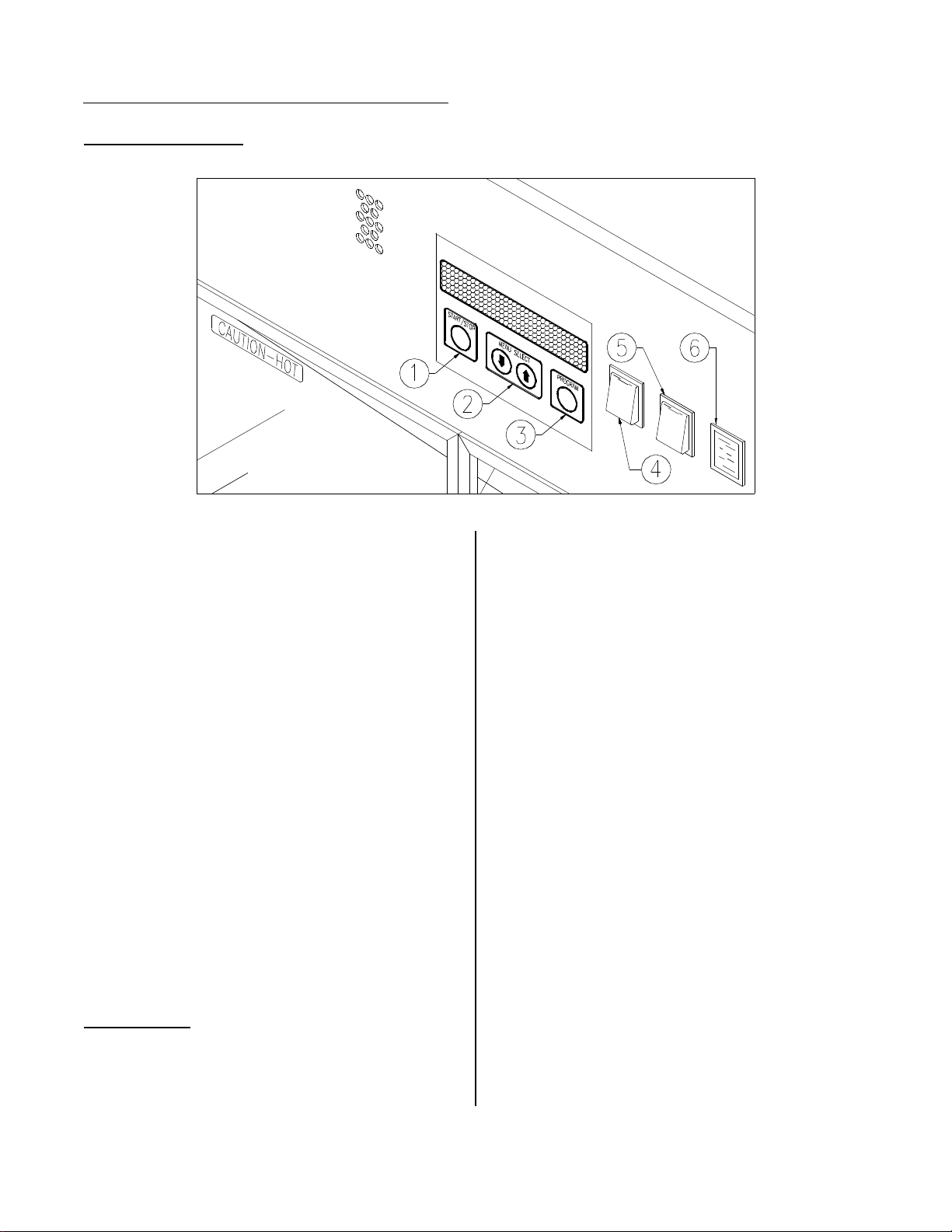
CONTROL PANEL Effective: V24B790013
FAMILIARIZATION:
1. Start/Stop Button: Press to start or
stop a cook cycle. To stop a cook cycle
or hold mode, press and hold for several seconds.
2. Menu Select buttons: Used to select
desired programmable choices and to
change program values.
3. Program Button: Used to enter and
exit programming mode.
4. Jog Switch: Gradually turns spits for
easy removal of product when unit is
ON and one or both doors are open.
5. Power Switch: This switch has two
positions: On and OFF.
6. Heat On Light: Illuminates when interior is being heated.
MAIN MENU:
• 000F = Cook temperature in degrees
Fahrenheit.
• 00:00:00 = Cook time in hours:minutes:seconds.
• #1 CK, #2 CK, etc. = Specific product to
be programmed.
Turn power switch ON. Display alternates
between LOW TEMP and STANDBY 000F.
Press the UP or DOWN buttons to select
desired main menu item:
• STANDBY 000F: Maintains a lower interior temperature during non-peak hours.
• #1 CK = 000F 00:00:00
• #2 CK = 000F 00:00:00
• #3 CK = 000F 00:00:00
• #4 CK = 000F 00:00:00
• #5 CK = 000F 00:00:00
• #6 CK = 000F 00:00:00
• #7 CK = 000F 00:00:00
• #8 CK = 000F 00:00:00
• #9 CK = 000F 00:00:00
• #10 CK = 000F 00:00:00
MANUAL 000F: Allows quick programming
of time and temperature for non-standard products.
Manual #13210 3/97 4 - 2
Page 23

CONTROLLER PROGRAMMING
See WHOLE CHICKEN for program settings.
PRODUCTS #1 - #10:
A = Operator Action
R = Controller Response
A: Press the UP or DOWN buttons to select
PRODUCT #1 - #10. Press and hold
PROGRAM button until controller enters
program mode.
R: Display reads TYPE? CONVECTION,
COOK AND HOLD, or SLOW COOK
AND HOLD.
A: Press UP or DOWN buttons to select
SLOW COOK AND HOLD. Press PROGRAM button.
R: Display reads HOLD MODE: ON or OFF.
AUTO COMPENSATE indicates timing
method. When OFF, controller operates
as a regular timer. When ON, controller
monitors interior temperature and
adjusts time to compensate for temperature fluctuations. Time will have to be
adjusted for larger product and frozen
product.
A: Press UP or DOWN buttons to make
selection. Press PROGRAM button.
R: Display reads COOK TIME = 00:00:00.
A: Press UP or DOWN buttons to make first
digit selection. Press PROGRAM button. Repeat for last five digits. Press
PROGRAM button to exit program
mode.
OR
R: If HOLD MODE is ON, display reads #00
HLD = 000F 00:00.
A: Press UP or DOWN buttons to make
selection. Select ON to cook and hold or
OFF to cook and serve. Press PROGRAM button.
R: Display reads OVEN COOK TEMP =
000F.
A: Press UP or DOWN buttons to make first
digit selection. Press PROGRAM button. Repeat last two digits.
R: Display reads AUTO COMPENSATE:
ON or OFF. AUTO COMPENSATE will
not appear in programming unless programmed OVEN COOK TEMP is above
300F.
A: Press UP or DOWN buttons to make first
digit selection. Press PROGRAM button. Repeat for last two digits. Press
PROGRAM button to exit program
mode.
R: Controller returns to main menu.
STANDBY 000F:
A: Press UP or DOWN buttons to select
STANDBY 000F. Press and hold PROGRAM button until controller enters program mode.
R: Display reads STANDBY: 000F.
A: Press UP or DOWN buttons to make first
digit selection. Press PROGRAM button. Repeat for last two digits. Press
PROGRAM button to exit program
mode.
Manual #13210 3/97 4 - 3
R: Controller returns to main menu.
Page 24
OPERATION AND PREPARATION
WARNING: All surfaces are HOT.
Hot surfaces could cause serious
burns. Use hot mitts when handling unit
components.
1. Place drip pan with drain plug into bottom of unit.
Note: The V24 regulates temperature to
the main menu displayed. Therefore before
placing product in unit for cooking, allow
interior temperature to reach programmed
temperature.
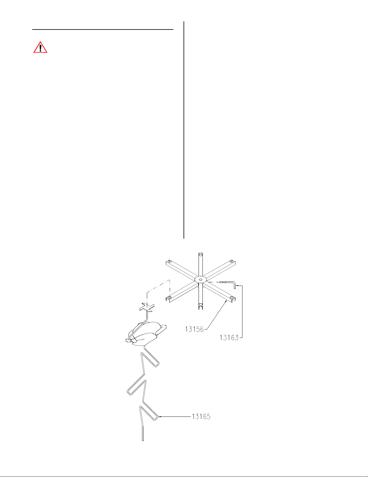
4. Install spit holder (#13156) onto center
top post and install locking pin
(#13163).
OR
Effective V24D790113: Install drain
plug into bottom of unit.
2. Place drain pan on rails beneath drip
pan.
Note: When draining drip pan, remember
the capacity of drip pan exceeds capacity of
drain pan.
3. Add 3/4 to 1 gallon of water into drip
pan.
A = Operator Action
R = Controller Response
A: Turn power switch ON.
R: Display reads STANDBY: 000F.
A: Press UP or DOWN buttons to select
desired main menu item. See CONTROLLER PROGRAMMING and
WHOLE CHICKEN for program settings.
Conversion kit #13217 is required to cook
products other than chicken. See CONVECTION OPERATION.
Manual #13210 3/97 4 - 4a Replace 4/97
Page 25
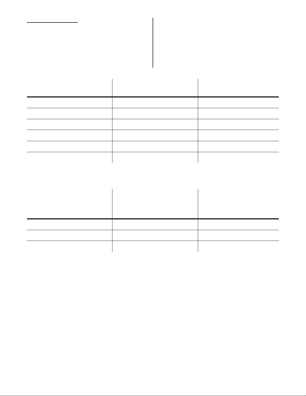
WHOLE CHICKEN:
Times below are suggested cook times.
Check interior meat temperature with a
meat thermometer. Meat is done when
white meat temperature is above 170F and
dark meat temperature is above 180F.
PROGRAM ITEM COOK AND SERVE
SETTINGS
COOK AND HOLD
SETTINGS
TYPE? SLOW COOK AND HOLD SLOW COOK AND HOLD
HOLD MODE OFF ON
OVEN COOK TEMP 300F 300F
AUTO COMPENSATE ON ON
COOK TIME see time chart below see time chart below
HOLD TEMP N/A 160F
BIRD SIZE SUGGESTED
COOK AND SERVE TIMES
Remove chicken at end of cook
cycle to prevent over cooking.
COOK AND HOLD TIMES
Hold a minimum of 25 minutes.
SUGGESTED
2.50 - 2.75 lb. 01:10:00 00:50:00
2.75 - 3.00 lb. 01:15:00 00:55:00
3.00 - 3.25 lb. 01:20:00 00:60:00
Manual #13210 3/97 4 - 5
Page 26
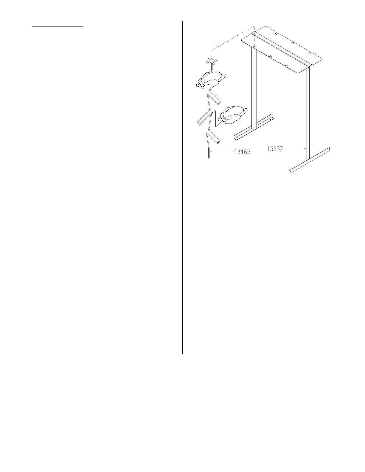
PREPARATION:
1. Purchase good quality whole chickens
±1/4 lb. for consistent results. Maximum bird weight should not exceed
3.25 lbs.
2. Unit capacity is 24 birds. Trim excess
skin and fat, remove giblets, and cut off
tail and neck. Rinse birds under cold
water.
3. Evenly distribute one heaping teaspoon Bro-Tisserie Seasoning inside
chicken cavity. Uniformly dust outside
with exception of wings. Too much
seasoning will darken or burn wings.
4. For lubrication, spray underside of spit
tops with Pam cooking spray.
5. Set spit (#13165) into prep station
holder (#13237). Place birds on spit by
folding wings back and crossing legs.
Note: Unit must be ON and pre-heated
before loading. Only cook balanced loads.
Install two spits (#13165) on opposite arms,
one spit every other arm, or all six spits.
Each spit should have an equal number of
birds.
6. Pull and lock gear drive release.
OR
Effective: V24B790013 - Open doors.
7. Install spits on spit holders nearest
door.
8. Push gear drive release in to access
empty spit holders. Repeat steps #6
and #7 until unit is loaded. Close
doors.
Manual #13210 3/97 4 - 6
OR
Effective: V24B790013 - Press and
hold JOG switch to access empty spit
holders. Repeat until unit is loaded.
Close doors.
Page 27

STARTING A COOK CYCLE:
1. Disconnect main power.
If required, press and hold START/STOP
button for several seconds to terminate a
hold or cook cycle.
A = Operator Action
R = Controller Response
A: Press START/STOP button to start cook
cycle.
R: Display reads time countdown.
OR
Display reads hold time counting up after
a cook cycle if HOLD MODE is ON.
A: When desired, press START/STOP but-
ton for several seconds to terminate hold
cycle. Remove product from unit.
CLEANING
CAUTION: Use only food approved
cleaners.
WARNING: Wait for unit to cool
before cleaning. Hot surfaces could
cause serious burns. Do not attempt to
clean hot glass. Glass may break causing
serious cuts.
Clean once daily . Use oven cleaner on hard
to clean surfaces. After washing any interior
component or surface, rinse with vinegar
and water solution (1/2 cup vinegar per gallon of water), and rinse thoroughly with clear
water.
2. Remove doors by fully opening and lifting up and out on bottom; set in sink
for cleaning. Do not use abrasive
cleaners on glass. To install doors,
insert upper pin first followed by lower
pin.
Note: When draining drip pan, remember
the capacity of drip pan exceeds capacity of
drain pan.
3. Remove spits and set in sink for cleaning. Remove drain plug in bottom of
drip pan. Use scraper to empty drip
pan. Remove drip pan and set in sink
for cleaning.
OR
Effective V24D790113: Wipe drip pan
clean using clean cloth or paper towel.
4. Empty drain pan. Set in sink for cleaning.
5. Loosen thumb screws on bottom of
heating element duct’s and remove.
Set in sink for cleaning.
6. Clean interior and exterior surfaces.
7. Sanitize components and surfaces
according to standard health regulations after washing.
4 - 7a
Manual #13210 3/97 Rev 5/08
Page 28

Page 29
5 - CONVECTION OPERATION
DUCT VARIATIONS
Convection kit (#14193) is required to cook
products other than chicken. When
installed, unit cooks as a convection oven.
WARNING: Be sure unit has cooled
before installing convection kit. Hot
surfaces could cause serious burns. Use
hot mitts when handling unit components.
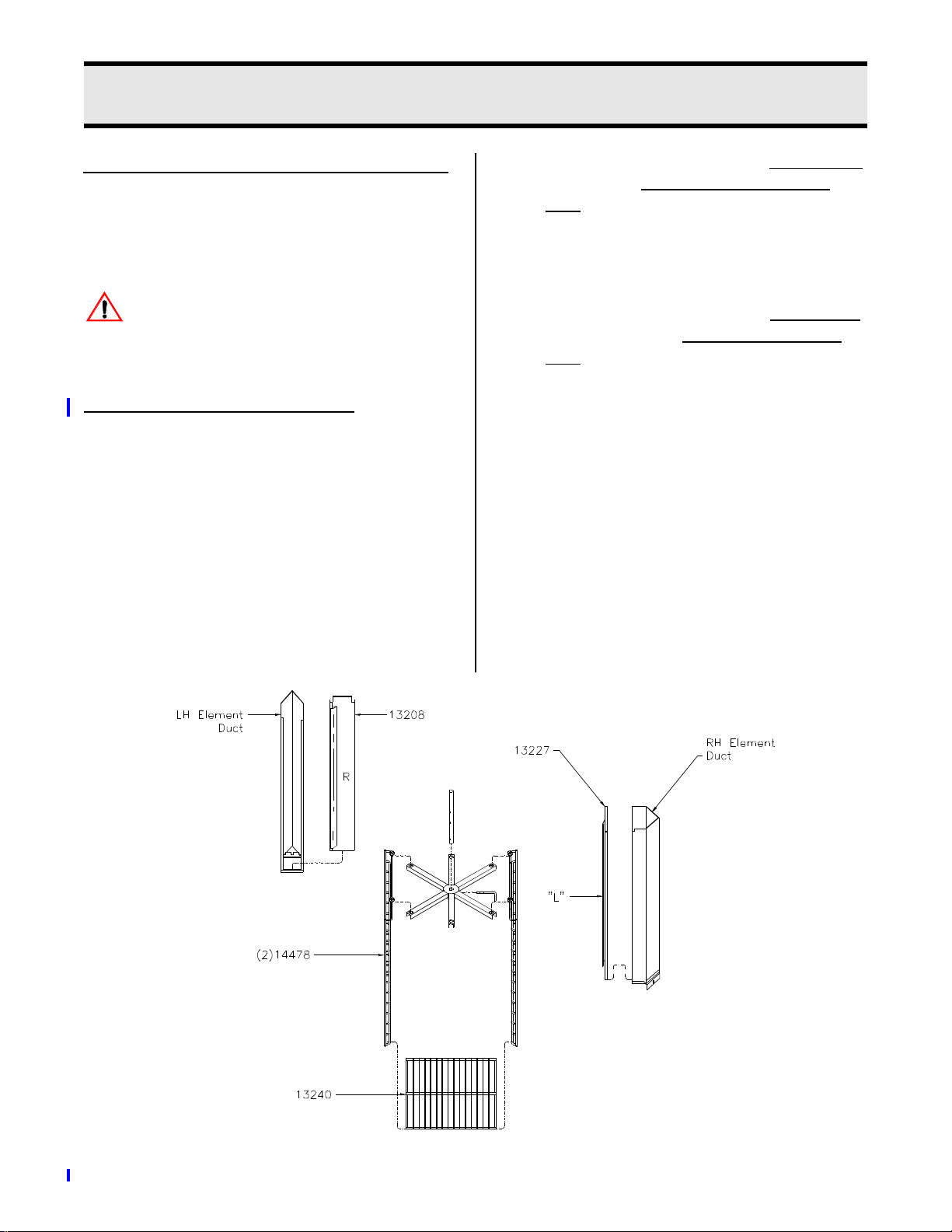
AIR CIRCULATION SYSTEM #2:
Used when cooking roasts, prime rib,
pizza, cookies, pies, muffins, biscuits,
etc. The duct covers should force air
toward the side panels and the upper duct
should not be installed.
1. Disconnect main power supply.
2. Install duct cover (#13208) marked “R”
by pushing onto left hand element
duct. Slide cover down so bottom tab
is inside bottom of element duct.
Opening of duct must face the left side
panel.
3. Install duct cover (#13227) marked “L”
by pushing onto right hand element
duct. Slide cover down so bottom tab
is inside bottom of element duct.
Opening of duct must face the right
side panel.
4. Hang one convection rack side
(#14478) between two of the spit carriage arms and the other between the
opposite two arms so that they are
across from each other with rungs
toward center.
5. Install one shelf rack (#13240) into the
bottom rung of the side racks. The others may be placed as needed.
5 - 1
Manual #13210 3/97 Rev. 11/02
Page 30
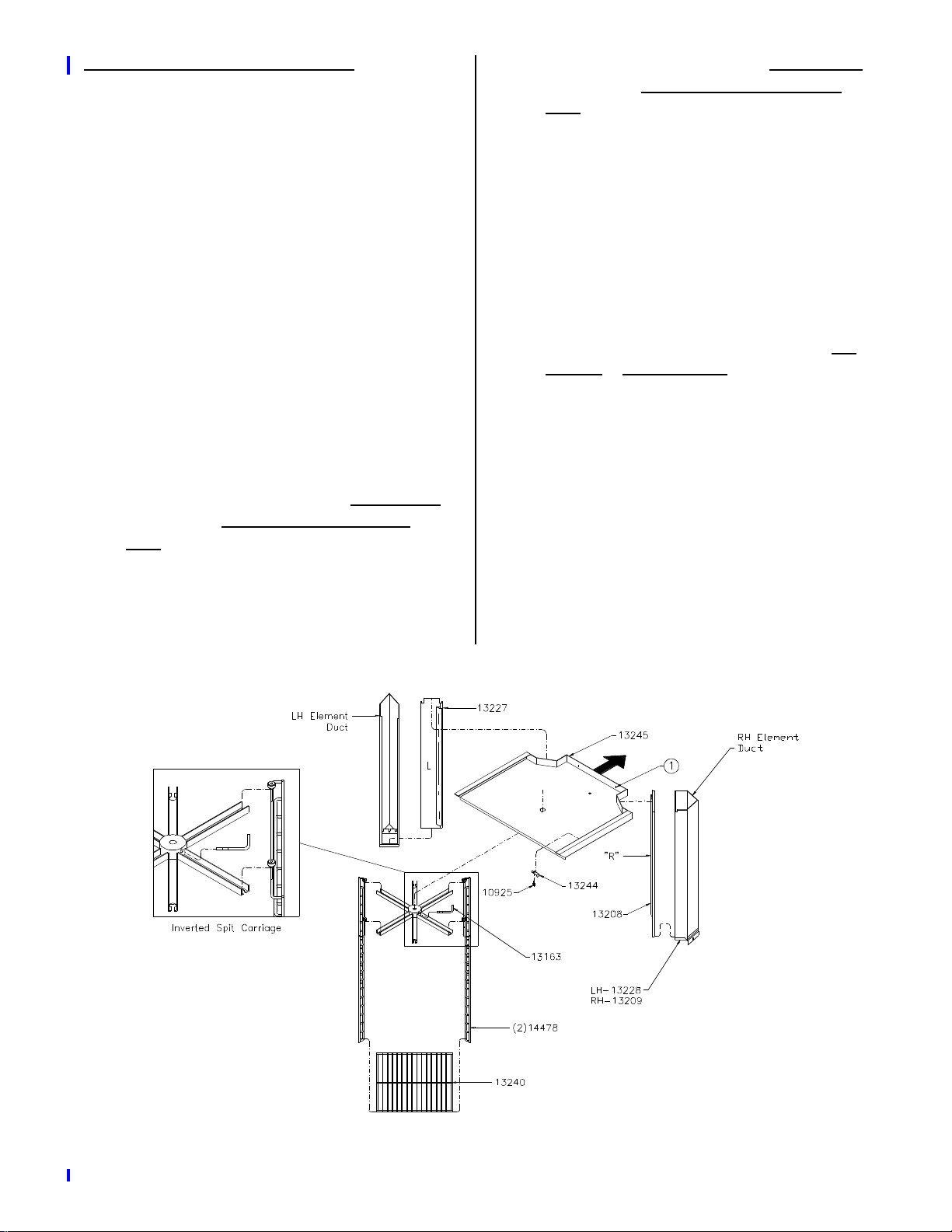
AIR CIRCULATION SYSTEM #1:
Used when cooking ribs only. The duct
covers should force air toward the back
panel and the upper duct must be installed.
1. Disconnect main power supply.
2. Remove locking pin and spit carriage.
See OPERATION AND PREPERATION in section 4.
3. Locate two upper duct tabs (#13244)
and thumbscrews (#10925). Mount
duct tabs to the top panel using the
thumbscrews. Do not tighten thumb
screws.
6. Install duct cover (#13208) marked “R”
by pushing onto right hand element
duct. Slide cover down so bottom tab
is inside bottom of element duct.
Opening of duct must face the back
panel.
7. Install two holes (1) in upper duct onto
pegs on back panel near top.
8. Turn duct tabs outward and under lip of
upper duct. Tighten thumbscrews.
9. Important: Reinstall spit carriage by
turning it upside down so the pin hole
is above the arm. Slide hub onto drive
shaft and insert drive pin (#13163).
4. Turn duct tabs toward center of unit.
5. Install duct cover (#13227) marked “L”
by pushing onto left hand element
duct. Slide cover down so bottom tab
is inside bottom of element duct.
Opening of duct must face the back
panel.
10. Hang one convection rack side
(#14478) between two of the spit carriage arms and the other between the
opposite two arms so that they are
across from each other.
11. Install one shelf rack (#13240) into the
bottom rung of the side racks. The others may be placed as needed.
5 - 2
Manual #13210 3/97 Rev. 11/02
Page 31

PROGRAMMING
PRODUCTS #1 - #10:
A = Operator Action
R = Controller Response
Convection Cooking (Baking):
A: Press the UP or DOWN buttons to select
PRODUCT #1 - #10. Press and hold
PROGRAM button until controller enters
program mode.
R: Display reads TYPE? CONVECTION,
COOK AND HOLD, or SLOW COOK
AND HOLD.
A: Press UP or DOWN buttons to select
CONVECTION. Press PROGRAM button.
R: Display reads OVEN COOK TEMP =
000F.
A: Press UP or DOWN buttons to make first
digit selection. Press PROGRAM button. Repeat for last two digits.
R: Display reads AUTO COMPENSATE:
ON or OFF. AUTO COMPENSATE will
not appear in programming unless programmed OVEN COOK TEMP is above
300F.
A: Press UP or DOWN buttons to make first
digit selection. Press PROGRAM button. Repeat for last five digits. Press
PROGRAM button to exit program
mode.
R: Controller returns to main menu.
Cook and Hold or
Slow Cook and Hold (Roasting):
A: Press UP or DOWN buttons to select
PRODUCT #1 - #10. Press and hold
PROGRAM button until controller enters
program mode.
R: Display reads TYPE? CONVECTION,
COOK AND HOLD, or SLOW COOK
AND HOLD.
A: Press UP or DOWN buttons to select
COOK AND HOLD or SLOW COOK
AND HOLD. Press PROGRAM button.
R: Display reads HOLD MODE: ON or
OFF.
A: Press UP or DOWN buttons to make
selection. Select ON to cook and hold or
OFF to cook and serve. Press PROGRAM button.
R: Display reads OVEN COOK TEMP =
000F.
AUTO COMPENSATE indicates timing
method. When OFF, controller operates
as a regular timer. When ON, controller
monitors interior temperature and
adjusts time to compensate for temperature fluctuations. Time will have to be
adjusted for larger product and frozen
product.
A: Press UP or DOWN buttons to make
selection. Press PROGRAM button.
R: Display reads COOK TIME = 00:00:00.
Manual #13210 3/97 5 - 3
A: Press UP or DOWN buttons to make first
digit selection. Press PROGRAM button. Repeat for last two digits.
Continued:
Page 32

R: Display reads AUTO COMPENSATE:
ON or OFF. AUTO COMPENSATE will
not appear in programming unless programmed OVEN COOK TEMP is above
300F.
AUTO COMPENSATE indicates timing
method. When OFF, controller operates
as a regular timer. When ON, controller
monitors interior temperature and
adjusts time to compensate for temperature fluctuations. Time will have to be
adjusted for larger product and frozen
product.
A: Press UP or DOWN buttons to make
selection. Press PROGRAM button.
STANDBY 000F:
A = Operator Action
R = Controller Response
A: Press UP or DOWN buttons to select
STANDBY 000F. Press and hold PROGRAM button until controller enters pro-
gram mode.
R: display reads STANDBY: 000F.
A: Press UP or DOWN buttons to make first
digit selection. Press PROGRAM but-
ton. Repeat for last two digits. Press
PROGRAM button to exit program
mode.
R: Display reads COOK TIME = 00:00:00.
A: Press UP or DOWN buttons to make first
digit selection. Press PROGRAM button. Repeat for last five digits. Press
PROGRAM button to exit program
mode.
OR
R: If HOLD MODE is ON, display reads #00
HLD = 000F 00:00.
A: Press UP or DOWN buttons to make first
digit selection. Press PROGRAM button. Repeat for last two digits. Press
PROGRAM button to exit program
mode.
R: Controller returns to main menu.
R: Controller returns to main menu.
MANUAL 000F:
A = Operator Action
R = Controller Response
A: Press UP or DOWN buttons to select
MANUAL 000F. Press PROGRAM but-
ton.
R: Display reads OVEN COOK TEMP =
000F.
A: Press UP or DOWN buttons to make first
digit selection. Press PROGRAM but-
ton. Repeat for last two digits.
R: Display reads COOK TIME = 00:00:00.
A: Press UP or DOWN buttons to make first
digit selection. Press PROGRAM but-
ton. Repeat for last five digits. Press
PROGRAM button to exit program
mode.
Manual #13210 3/97 5 - 4
R: Controller returns to main menu.
Page 33

OPERATION
WARNING: All surfaces are HOT.
Hot surfaces could cause serious
burns. Use hot mitts when handling unit
components.
A: Press UP or DOWN buttons to select
desired main menu item. See desired
recipe for programming settings. Pull
and lock gear drive release to stop rack
weldment rotation. Place product in unit
for cooking. Push gear drive release in.
1. Install drip pan with drain plug into bottom of unit.
OR
Effective V24D790113: Install drain
plug into bottom of unit.
2. Install drain pan on rails beneath drip
pan.
Note: When draining drip pan, remember
the capacity of drip pan exceeds capacity of
drain pan.
3. Add 3/4 to 1 gallon of water into drip
pan.
Note: The V24 regulates temperature to
the main menu displayed. Therefore before
placing product in unit for cooking, allow
interior temperature to reach programmed
temperature.
OR
Effective: V24B790013 - Press UP or
DOWN buttons to select desired main
menu item. See desired recipe for programming settings. Open doors and
press and hold JOG switch to control
rack weldment rotation. Place product in
unit for cooking. Close doors.
STARTING A COOK CYCLE:
A = Operator Action
R = Controller Response
If required, press and hold START/STOP
button for several seconds to terminate a
hold or cook cycle.
A: Press START/STOP button to start cook-
ing cycle.
R: Display reads time countdown.
A = Operator Action
OR
R = Controller Response
Display reads hold time counting up after
A: Turn power switch ON.
R: Display reads STANDBY: 000F.
a cook cycle if HOLD MODE is ON.
A: When desired, terminate hold cycle. Pull
and lock gear drive release to stop rack
weldment rotation. Remove product
from unit.
OR
Effective: V24B790013 - When desired,
terminate hold cycle. Open doors and
press and hold JOG switch to control
rack weldment rotation. Remove prod-
uct from unit.
Manual #13210 3/97 5 - 5a Replace 4/97
Page 34

CLEANING
CAUTION: Use only food approved
cleaners.
WARNING: Wait for unit to cool
before cleaning. Hot surfaces could
cause serious burns. Do not attempt to
clean hot glass. Glass may break causing
serious cuts.
3. Remove rack and set in sink for cleaning. Remove drain plug in bottom of
drip pan. Use scraper to empty drip
pan. Remove drip pan and set in sink
for cleaning.
OR
Effective V24D790113: Wipe drip pan
clean using clean cloth or paper towel.
Clean once daily . Use oven cleaner on hard
to clean surfaces. After washing any interior
component or surface, rinse with vinegar
and water solution (1/2 cup vinegar per gallon of water), and rinse thoroughly with clear
water.
1. Disconnect main power.
2. Remove doors by fully opening and lifting up and out on bottom; set in sink
for cleaning. Do not use abrasive
cleaners on glass. To install doors,
insert upper pin first followed by lower
pin.
Note: When draining drip pan, remember
the capacity of drip pan exceeds capacity of
drain pan.
4. Empty drain pan. Set in sink for cleaning.
5. Remove upper and element air duct’s.
Set in sink for cleaning.
6. Loosen thumb screw’s on bottom of
heating element duct’s and remove.
Set in sink for cleaning.
7. Clean interior and exterior surfaces.
8. Sanitize components and surfaces
according to standard health regulations after washing.
WARNING: Rags or papers contain-
ing cooking oil can catch fire if
exposed to heat. Laundering will not
remove the oil. Dispose of all oil-soiled
papers and rags in a trash container that is
in a ventilated area away from all cooking
equipment or other heat sources such as
direct sunlight.
5 - 6
Manual #13210 3/97 Rev 5/08
Page 35
6 - RECIPES
All cook times are suggested. Due to variations in product weight and desired doneness, time, temperature, or both may have
to be adjusted.
BEEF AND PORK
BABY BACK PORK RIBS:
See Air Circulation System #1.
MAX LOAD . . . . 36 slabs (3 slabs per rack)
MAX HOLD TIME . . . . . . . . . . . . . 03:00:00
Special Instructions:
1. Remove membrane.
2. Marinate ribs in stainless steel or plastic container with 4 oz. Broaster Rib-ite
per gallon of water, be sure ribs are
covered with marinade.
3. Marinate 8 hours minimum 12 hours
maximum (overnight preferred).
4. Drain marinade and sprinkle each side
of slab with 1 tablespoon Broaster
Foods Barbecue Seasoning and rub in
lightly.
5. Final internal temperature of meat is
160 to 170F.
Optional:
1. Add 1 fl. oz. Mist-Aire Liquid Smoke
per gallon of marinade.
2. Half hour before completion of hold
cycle, brush each side of slab with
Cranston Farms Country Style BBQ
Sauce.
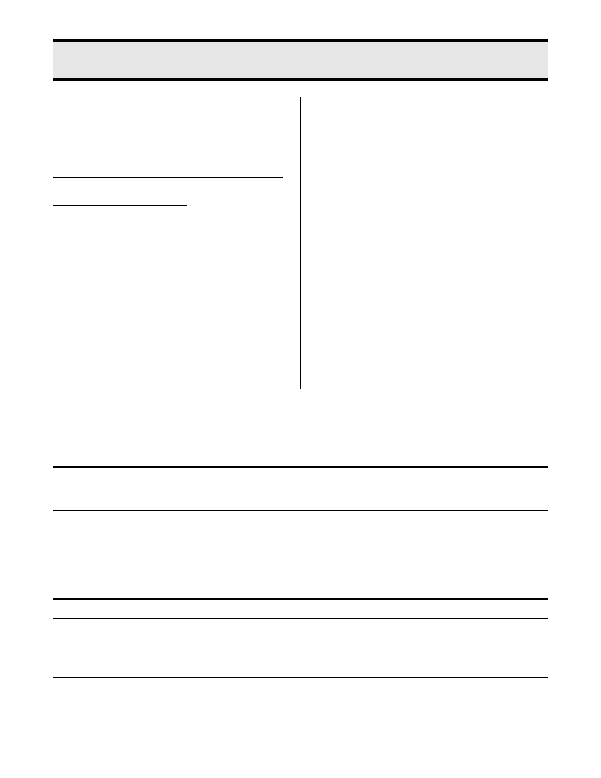
SIZE SUGGESTED
COOK AND SERVE TIMES
Remove product at end of cook cycle
to prevent over cooking.
1 3/4 to 2 lbs. per slab 01:45:00
00:30:00 min. additional per
1/2 lb. per slab
2 to 3 lbs. per slab See Above N/A
PROGRAM ITEM SUGGESTED
COOK AND SERVE SETTINGS
TYPE? SLOW COOK AND HOLD N/A
HOLD MODE OFF/ON N/A
OVEN COOK TEMP 250F N/A
AUTO COMPENSATE N/A N/A
COOK TIME see time chart above N/A
HOLD TEMP 155F N/A
COOK AND HOLD SETTINGS
SUGGESTED
COOK AND HOLD TIMES
N/A
SUGGESTED
Manual #13210 3/97 6 - 1
Page 36
FRESH TOP (INSIDE) or BOTTOM
ROUND:
See Air circulation System #2.
MAX LOAD . . . . . . . . . . . . . . . . . . . . 80 lbs.
(2 - 20 lb. roasts per rack; 2 racks used)
MIN HOLD TIME . . . . . . . . . . . . . . 05:00:00
MAX HOLD TIME . . . . . . . . . . . . . 20:00:00
Special Instructions:
1. Cook roasts unwrapped.
2. Set roasts directly on rack, not in pans.
3. Final internal temperature of meat:
Rare . . . . . . . . . . . . . . . . .130 to 140F
Medium . . . . . . . . . . . . . . .140 to 150F
Well . . . . . . . . . . . . . . . . . .150 to 150F
Optional:
1. Season with Broaster Foods Prep Seasoning if desired.
SIZE SUGGESTED
COOK AND SERVE TIMES
Remove product at end of cook cycle
to prevent over cooking.
15 to 20 lb. roast N/A 00:13:00 min. per lb. for first roast
00:20:00 min. per additional roast
PROGRAM ITEM SUGGESTED
COOK AND SERVE SETTINGS
TYPE? N/A SLOW COOK AND HOLD
HOLD MODE N/A ON
OVEN COOK TEMP N/A 250F
AUTO COMPENSATE N/A N/A
COOK TIME N/A see time chart above
HOLD TEMP N/A 150F rare
SUGGESTED
COOK AND HOLD TIMES
SUGGESTED
COOK AND HOLD TIMES
155F medium
160F well
Manual #13210 3/97 6 - 2
Page 37
FRESH PRIME RIB
:
Optional:
See Air Circulation System #2.
MAX LOAD . . . . . . . . . . . . . . . . . . . . 80 lbs.
(2 - 20 lb. roasts per rack; 2 racks used)
MIN HOLD TIME . . . . . . . . . . . . . . 04:00:00
MAX HOLD TIME . . . . . . . . . . . . . 22:00:00
Special Instructions:
1. Purchase with exterior fat cap.
2. Cook unwrapped.
3. Set directly on rack, not in pans.
4. Final internal temperature of meat:
Rare . . . . . . . . . . . . . . . . .130 to 140F
Medium . . . . . . . . . . . . . . .140 to 150F
Well . . . . . . . . . . . . . . . . . .150 to 160F
SIZE SUGGESTED
COOK AND SERVE TIMES
Remove product at end of cook cycle
to prevent over cooking.
1. Season with Broaster Foods Prep if
desired.
SUGGESTED
COOK AND HOLD TIMES
15 to 20 lb. N/A 00:08:00 min. per lb. for first
prime
00:20:00 min. per additional prime
PROGRAM ITEM SUGGESTED
COOK AND SERVE SETTINGS
TYPE? N/A SLOW COOK AND HOLD
HOLD MODE N/A ON
OVEN COOK TEMP N/A 250F
AUTO COMPENSATE N/A N/A
COOK TIME N/A see time chart above
HOLD TEMP N/A 150F rare
COOK AND HOLD SETTINGS
SUGGESTED
155F medium
160F well
Manual #13210 3/97 6 - 3
Page 38
FRESH PORK LOIN
:
Option:
See Air Circulation System #2.
MAX LOAD . . . . . . . . . . . . . . . . . . . . 72 lbs.
(2 - 12 lb. roasts per rack; 3 racks used)
MIN HOLD TIME . . . . . . . . . . . . . . 05:00:00
MAX HOLD TIME . . . . . . . . . . . . . 10:00:00
Special Instructions:
1. Cook unwrapped.
2. Set directly on rack, not in pans.
3. Final internal temperature of meat is
160 to 170F.
SIZE SUGGESTED
COOK AND SERVE TIMES
Remove product at end of cook cycle
to prevent over cooking.
8 - 12 lb. N/A 00:24:00 min. per lb. for first loin
1. Season with Broaster Foods Prep if
desired.
SUGGESTED
COOK AND HOLD TIMES
00:05:00 min. per additional full
rack
PROGRAM ITEM SUGGESTED
COOK AND SERVE SETTINGS
TYPE? N/A SLOW COOK AND HOLD
HOLD MODE N/A ON
OVEN COOK TEMP N.A 250F
AUTO COMPENSATE N/A N/A
COOK TIME N/A see time chart above
HOLD TEMP N/A 170F
COOK AND HOLD SETTINGS
SUGGESTED
Manual #13210 3/97 6 - 4
Page 39
FRESH BOSTON BUTT PORK ROAST
:
Optional:
See Air Circulation System #2.
MAX LOAD . . . . . . . . . . . . . . . . . . . . 80 lbs.
(4 - 5 lb. roasts per rack; 4 racks used)
MIN HOLD TIME . . . . . . . . . . . . . . 03:00:00
MAX HOLD TIME . . . . . . . . . . . . . 05:00:00
Special Instructions:
1. Cook unwrapped.
2. Set directly on rack, not in pans.
3. Final internal temperature of meat is
160 to 170F.
SIZE SUGGESTED
COOK AND SERVE TIMES
Remove product at end of cook cycle
to prevent over cooking.
4 to 6 lb. N/A 00:36:00 min. per lb. for first roast
1. Season with Broaster Foods Prep if
desired.
SUGGESTED
COOK AND HOLD TIMES
00:05:00 min. per additional full
rack
PROGRAM ITEM SUGGESTED
COOK AND SERVE SETTINGS
TYPE? N/A SLOW COOK AND HOLD
HOLD MODE N/A ON
OVEN COOK TEMP N/A 250F
AUTO COMPENSATE N/A N/A
COOK TIME N/A see time chart above
HOLD TEMP N/A 170F
COOK AND HOLD SETTINGS
SUGGESTED
Manual #13210 3/97 6 - 5
Page 40
VEGETABLES
Optional:
FRESH POTATOES:
See Air Circulation System #2.
MAX LOAD . . . . . . . . . . . . . . . . 72 potatoes
(12 potatoes per rack; 6 racks used)
Special Instructions:
1. Cook unwrapped.
2. Set directly on rack, not in pans.
QUANTITY SUGGESTED
COOK AND SERVE TIMES
Remove product at end of cook cycle
to prevent over cooking.
72 potatoes 00:01:00 N/A
1. Season with Broaster Foods Prep if
desired.
SUGGESTED
COOK AND HOLD TIMES
PROGRAM ITEM SUGGESTED
COOK AND SERVE SETTINGS
TYPE? CONVECTION N/A
HOLD MODE N/A N/A
OVEN COOK TEMP 400F N/A
AUTO COMPENSATE ON N/A
COOK TIME see time chart above N/A
HOLD TEMP N/A N/A
COOK AND HOLD SETTINGS
SUGGESTED
Manual #13210 3/97 6 - 6
Page 41
BREADS
FRESH BISCUITS:
See Air Circulation System #2.
MAX LOAD . . . . . . . . . . . . . . . .216 Biscuits
(36 biscuits per rack; 6 racks used)
Special Instructions:
1. Place biscuits on lightly greased cookie
sheet.
2. Brush with butter immediately after
removing from oven.
PROGRAM ITEM SUGGESTED
COOK AND SERVE SETTINGS
TYPE? CONVECTION N/A
HOLD MODE N/A N/A
OVEN COOK TEMP 400F N/A
AUTO COMPENSATE ON N/A
COOK TIME 00:23:00 N/A
HOLD TIME N/A N/A
COOK AND HOLD SETTINGS
SUGGESTED
Manual #13210 3/97 6 - 7
Page 42
MUFFINS (1 TO 1 1/4 oz.)
:
See Air Circulation System #2.
MAX LOAD . . . . . . . . . . . . . . . . 144 muffins
(24 muffins per rack; 6 racks used)
Special Instructions:
1. Using a #30 scoop, put batter in lightly
greased or paper-lined muffin tin.
Dimension of muffin cup: 2 3/4” top; 1
1/2” bottom; 1 1/8” deep.
PROGRAM ITEM SUGGESTED
COOK AND SERVE SETTINGS
TYPE? CONVECTION N/A
HOLD MODE N/A N/A
OVEN COOK TEMP 375F N/A
AUTO COMPENSATE ON N/A
COOK TIME 00:14:00 to 00:17:00 N/A
HOLD TEMP N/A N/A
COOK AND HOLD SETTINGS
SUGGESTED
Manual #13210 3/97 6 - 8
Page 43
MUFFINS (1 1/2 TO 2 oz.)
:
See Air Circulation System #2.
MAX LOAD . . . . . . . . . . . . . . . . 144 muffins
(24 muffins per rack; 6 racks used)
Special Instructions:
1. Using a #20 scoop, put batter in lightly
greased or paper-lined muffin tin.
Dimension of muffin cup: 2 3/4” top; 1
3/4” bottom; 1 1/4” deep.
PROGRAM ITEM SUGGESTED
COOK AND SERVE SETTINGS
TYPE? CONVECTION N/A
HOLD MODE N/A N/A
OVEN COOK TEMP 375F N/A
AUTO COMPENSATE ON N/A
COOK TIME 00:20:00 to 00:23:00 N/A
HOLD TEMP N/A N/A
COOK AND HOLD SETTINGS
SUGGESTED
Manual #13210 3/97 6 - 9
Page 44
MUFFINS (3 3/4 TO 4 oz.)
:
See Air Circulation System #2.
MAX LOAD . . . . . . . . . . . . . . . . . 72 muffins
(12 muffins per rack; 6 racks used)
Special Instructions:
1. Using a #8 scoop, put batter in lightly
greased or paper-lined muffin tin.
Dimension of muffin cup: 3 1/2” top; 2
3/4” bottom; 1 1/4” deep.
PROGRAM ITEM SUGGESTED
COOK AND SERVE SETTINGS
TYPE? CONVECTION N/A
HOLD MODE N/A N/A
OVEN COOK TEMP 375F N/A
AUTO COMPENSATE ON N/A
COOK TIME 00:22:00 to 00:25:00 N/A
HOLD TEMP N/A N/A
COOK AND HOLD SETTINGS
SUGGESTED
Manual #13210 3/97 6 - 10
Page 45
DESSERTS
FROZEN COOKIES:
See Air Circulation System #2.
MAX LOAD . . . . . . . . . . . . . . . .144 cookies
(12 cookies per rack; 12 racks used)
Special Instructions:
1. Place cookies on lightly greased
cookie sheets.
PROGRAM ITEM SUGGESTED
COOK AND SERVE SETTINGS
TYPE? CONVECTION N/A
HOLD MODE N/A N/A
OVEN COOK TEMP 350F N/A
AUTO COMPENSATE ON N/A
COOK TIME 00:12:00 to 00:15:00 N/A
HOLD TEMP N/A N/A
COOK AND HOLD SETTINGS
SUGGESTED
Manual #13210 3/97 6 - 11
Page 46
FROZEN FRUIT PIE
:
See Air Circulation System #2.
MAX LOAD . . . . . . . . . . . . . . . . . . . 12 pies
(2 pies per rack; 6 racks used)
Special Instructions:
1. Place pies directly on racks.
PROGRAM ITEM SUGGESTED
COOK AND SERVE SETTINGS
TYPE? CONVECTION N/A
HOLD MODE N/A N/A
OVEN COOK TEMP 375F N/A
AUTO COMPENSATE ON N/A
COOK TIME 01:25:00 N/A
HOLD TEMP N/A N/A
COOK AND HOLD SETTINGS
SUGGESTED
Manual #13210 3/97 6 - 12
Page 47
FROZEN CUSTARD PIE
:
See Air Circulation System #2.
MAX LOAD . . . . . . . . . . . . . . . . . . . 12 pies
(2 pies per rack; 6 racks used)
Special Instructions:
1. Place pies directly on racks.
2. Allow pies to cool one hour after baking
so filing can “set-up”.
PROGRAM ITEM SUGGESTED
COOK AND SERVE SETTINGS
TYPE? CONVECTION N/A
HOLD MODE N/A N/A
OVEN COOK TEMP 350F N/A
AUTO COMPENSATE ON N/A
COOK TIME 01:30:00 N/A
HOLD TEMP N/A N/A
COOK AND HOLD SETTINGS
SUGGESTED
Manual #13210 3/97 6 - 13
Page 48
MISCELLANEOUS
FROZEN 20 oz. 12 INCH PIZZA:
See Air Circulation System #2.
MAX LOAD . . . . . . . . . . . . . . . . . .12 pizzas
(1 pizza per rack; 12 racks used)
Special Instructions:
1. Place pizzas directly on racks.
PROGRAM ITEM SUGGESTED
COOK AND SERVE SETTINGS
TYPE? CONVECTION N/A
HOLD MODE N/A N/A
OVEN COOK TEMP 375F N/A
AUTO COMPENSATE ON N/A
COOK TIME 00:20:00 N/A
HOLD TEMP N/A N/A
COOK AND HOLD SETTINGS
SUGGESTED
Manual #13210 3/97 6 - 14
Page 49
FRESH TURKEY
:
Optional:
See Air Circulation System #2.
MAX LOAD . . . . . . . . . . . . . . . . . . 2 turkeys
(1-20 lb. turkey per rack; 2 racks used)
MAX HOLD TIME . . . . . . . . . . . . . 08:00:00
Special Instructions:
1. Purchase 15 - 20 lb. turkeys.
2. Set birds directly on rack, not in pans.
3. Final internal temperature of meat:
Breast . . . . . . . . . . . . . . . . . . . . . 170F
Thigh . . . . . . . . . . . . . . . . . . . . . . 180F
SIZE SUGGESTED
COOK AND SERVE TIMES
Remove product at end of cook cycle
to prevent over cooking.
15 to 20 lb. turkey 00:16:00 min. per lb. for first
00:20:00 min. per additional
1. Brush bird(s) with oil if desired.
2. Season with Broaster Foods Prep if
desired.
SUGGESTED
COOK AND HOLD TIMES
N/A
turkey
turkey
PROGRAM ITEM SUGGESTED
COOK AND SERVE SETTINGS
TYPE? SLOW COOK AND HOLD N/A
HOLD MODE ON N/A
OVEN COOK TEMP 270F N/A
AUTO COMPENSATE N/A N/A
COOK TIME see time chart above N/A
HOLD TEMP 170F N/A
COOK AND HOLD SETTINGS
SUGGESTED
Manual #13210 3/97 6 - 15
Page 50

Page 51

 Loading...