


SERVICE MANUAL
BROASTER® 2400
PRESSURE FRYER
Be sure ALL installers read, understand, and have access to this manual at all times.
Genuine Broaster Chicken®, Broasted®, Broaster Chicken®, Broaster Foods®. and Broasterie® are registered trademarks. Usage is available only to licensed operators with written authorization from the Broaster Company.
|
Broaster Company |
|
|
|
2855 Cranston Road, Beloit, WI 53511-3991 |
|
|
|
608/365-0193 |
broaster.com |
|
Design Certified By: |
Manual #15460 8/02 |
Rev 10/16 |
© 2002 Broaster Company |
CSA & NSF |
Printed In U.S.A. |
||
FOR YOUR SAFETY
Do not use or store gasoline or other flammable vapors or liquids in the vicinity of this or any other appliance.
Improper installation, adjustments, alteration, service or maintenance can cause property damage, injury or death. Read the installation, operating and maintenance instructions thoroughly before installing or servicing this equipment.
For the sake of safety and clarity, the following words used in this manual are defined as follows:
Indicates an imminently hazardous situation which, if not avoided, could result in serious injury or death.
Indicates a potentially hazardous situation which, if not avoided, could result in serious injury or death.
Indicates a potentially hazardous situation which, if not avoided, could result in minor injury, property damage or both.
All adjustments and repairs shall be made by an authorized Broaster Company representative.
If there is a power failure, turn cook/filter switch OFF. On the Model 2400GH, also slide switch on gas valve OFF. DO NOT attempt to operate unit during a power failure.
Failure to read and understand this manual
completely could result in serious injury or death. Be sure ALL operators read, understand and have access to this manual at all times.
Rags or paper containing cooking oil can catch fire
if exposed to heat. Laundering will not remove the oil. Dispose of all oil-soiled papers and rags in a trash container that is in a ventilated area away from all cooking equipment or other heat sources such as direct sunlight.
If at any time the POWER ON light does not turn off when the cook/filter switch is moved to
the OFF position, disconnect the power to the fryer and contact your local Broaster Company representative for service immediately.
DO NOT operate unit without filter pan and filter
pan cover in its proper position. Filter pan cover must be wiped clean after each filtering cycle.
Make sure Pressure Relief Valve and Pressure Gauge ports on bottom of cover are clear of any oil or grease buildup.
Make sure Pressure Relief Valve and Pressure Gauge ports on bottom of cover are clear of any
oil or grease buildup.
2400GH: Post, in prominent locations, instructions to be followed in the event that the user smells gas. This information can be obtained from your local gas supplier.
cont’d on next page
W-1
broaster.com Manual #15460 8/02 Rev: 10/15

Make sure a restraining device is used that
complies with the Standard for
Commercial Gas Ranges, ANSI Z83.11/ CSA 1.8 to guard against transmission of strain to the gas connectors.
Failure to restrain the fryer could allow it to move, causing hot shortening to spill
out, or a possible break in the gas line causing an explosive condition.
W-2
broaster.com Manual #15460 8/02 Rev: 10/15

TABLE OF CONTENTS
1 - WARNING SIGNS ......................................................................................................... |
1 - 1 |
2 - ELECTRIC POWER SUPPLY ....................................................................................... |
2 - 1 |
WIRING DIAGRAMS ELECTRIC |
|
DOMESTIC ...................................................................................................... |
2 - 1 |
EXPORT .......................................................................................................... |
2 - 4 |
EU .................................................................................................................... |
2 - 6 |
WIRING DIAGRAMS GAS |
|
DOMESTIC ...................................................................................................... |
2 - 9 |
EXPORT .......................................................................................................... |
2 - 9 |
EU .................................................................................................................. |
2 - 10 |
3 - CONTROL PANEL ........................................................................................................ |
3 - 1 |
TEMP-N-TIME FAMILIARIZATION .............................................................................. |
3 - 1 |
CONTROLLER PROGRAMMING................................................................................ |
3 - 2 |
PRESET COOK MODE................................................................................................ |
3 - 3 |
PROGRAMMING METHOD 1 ................................................................................ |
3 - 3 |
PROGRAMMING METHOD 2 ................................................................................ |
3 - 4 |
WARNING DISPLAYS ................................................................................................. |
3 - 4 |
DISPLAY ACTUAL TEMPERATURE ............................................................................ |
3 - 5 |
CALIBRATION ............................................................................................................. |
3 - 6 |
ACCESS FOR SERVICE.............................................................................................. |
3 - 5 |
COOK/FILTER SWITCH .............................................................................................. |
3 - 7 |
HI-LIMIT CONTROL .................................................................................................... |
3 - 7 |
POWER ON INDICATOR LIGHT.................................................................................. |
3 - 9 |
SOLID STATE CONTROLLER ..................................................................................... |
3 - 9 |
TEMPERATURE SENSOR PROBE............................................................................ |
3 - 10 |
4 - POWER INPUT BOX..................................................................................................... |
4 - 1 |
TIMER SWITCH........................................................................................................... |
4 - 1 |
CONTROL ROD .......................................................................................................... |
4 - 2 |
2400GH PRESSURE FRYER....................................................................................... |
4 - 3 |
TRANSFORMER (2400GH) ......................................................................................... |
4 - 3 |
2400E PRESSURE FRYER.......................................................................................... |
4 - 4 |
CONTACTORS (2400E) ............................................................................................... |
4 - 4 |
FUSE (2400E) .............................................................................................................. |
4 - 5 |
HEATING ELEMENT (2400E)....................................................................................... |
4 - 6 |
RELAY (2400E) ............................................................................................................ |
4 - 8 |
PRE-HEAT RELAYS (2400E)........................................................................................ |
4 - 8 |
i
broaster.com Manual #15460 8/02 Rev 6/16

5 - COVER, YOKE, & LIFT ................................................................................................. |
5 - 1 |
FAMILIARIZATION....................................................................................................... |
5 - 1 |
PROPER COVER OPERATION ................................................................................... |
5 - 2 |
GAS SPRINGS ............................................................................................................ |
5 - 3 |
ADJUSTMENTS .......................................................................................................... |
5 - 3 |
COVER AND YOKE REMOVAL ................................................................................... |
5 - 4 |
COVER AND YOKE DISASSEMBLY ........................................................................... |
5 - 5 |
COVER AND YOKE ASSEMBLY ................................................................................. |
5 - 6 |
CHECK CAM OPERATION.......................................................................................... |
5 - 6 |
LIFT REMOVAL ........................................................................................................... |
5 - 7 |
SLIDE ROD AND BEARING REPLACEMENT ............................................................. |
5 - 8 |
PRESSURE GAUGE.................................................................................................... |
5 - 9 |
SAFETY RELIEF VALVES ............................................................................................ |
5 - 9 |
6 - PRESSURE SYSTEM ................................................................................................... |
6 - 1 |
EXHAUST DRAIN TUBE.............................................................................................. |
6 - 2 |
EXHAUST TANK.......................................................................................................... |
6 - 2 |
EXHAUST TUBE.......................................................................................................... |
6 - 3 |
PRESSURE REGULATING VALVE............................................................................... |
6 - 3 |
7 - MAIN BURNER SYSTEM ............................................................................................. |
7 - 1 |
BURNER INFORMATON ............................................................................................. |
7 - 1 |
GAS CONVERSION .................................................................................................... |
7 - 1 |
LIGHTING INSTRUCTIONS ........................................................................................ |
7 - 1 |
VENTILATION.............................................................................................................. |
7 - 2 |
GAS VALVE ................................................................................................................. |
7 - 2 |
FLAME ADJUSTMENTS ............................................................................................. |
7 - 3 |
MAIN BURNER FLAME ADJUSTMENT ..................................................................... |
7 - 5 |
MAIN BURNER ORIFICE............................................................................................. |
7 - 6 |
PILOT BURNER ORIFICE ........................................................................................... |
7 - 7 |
COMBUSTION CHAMBER ......................................................................................... |
7 - 8 |
8 - DRAIN VALVE AND FILTER SYSTEM.......................................................................... |
8 - 1 |
DRAIN VALVE.............................................................................................................. |
8 - 1 |
FILTER PAN................................................................................................................. |
8 - 2 |
CHECK VALVE ............................................................................................................ |
8 - 3 |
MOTOR ....................................................................................................................... |
8 - 4 |
PUMP.......................................................................................................................... |
8 - 5 |
ii
broaster.com Manual #15460 8/02 Rev 12/15

9 - TROUBLESHOOTING .................................................................................................. |
9 - 1 |
ELECTRICAL TIPS ...................................................................................................... |
9 - 1 |
SOLID STATE CONTROLLER TIPS ............................................................................ |
9 - 2 |
SMART TOUCH CONTROLLER TIPS ........................................................................ |
9 - 3 |
GAS TIPS .................................................................................................................... |
9 - 4 |
COVER, YOKE, AND SLIDE TIPS ............................................................................... |
9 - 4 |
PRESSURE SYSTEM TIPS ......................................................................................... |
9 - 5 |
PRODUCT TIPS .......................................................................................................... |
9 - 6 |
FRESH CHICKEN ............................................................................................... |
9 - 6 |
FROZEN IQF CHICKEN ..................................................................................... |
9 - 7 |
FILTERING TIPS............................................................................................................. |
9 - 8 |
TROUBLESHOOTING FLOW CHART - 2400GH......................................................... |
9 - 10 |
TROUBLESHOOTING FLOW CHART - 2400E ............................................................ |
9 - 12 |
iii
broaster.com Manual #15460 8/02 Rev 3/16

1 - WARNING SIGNS
When servicing a Broaster® pressure fryer, be sure all safety devices and warning signs are in place and legible. If not, the Broaster Company should be notified in writing of the lack of warning signs and the existence of an unsafe condition.
If you need replacement warning signs or manuals, contact an authorized Broaster Company representative or the Broaster Company Service Department at:
(608) 365-0193
CAUTION!CHECK OIL LEVEL BEFORE OPERATING


 1
1 2
2
 3
3


 4
4 5
5 6
6


 7
7
 8
8
 9
9
0 |
 CAUTION:DO NOT OPERATE THIS FRYER WITHOUT FILTER PAN & COVER IN PLACE
CAUTIO |
|
|
|
|
N!C |
|
|
|
|
HECK |
OIL |
|
|
|
|
LEVEL |
|
|
|
|
|
BEFORE |
|
|
|
|
|
OPE |
|
|
|
|
|
|
|
|
|
|
RATING |
|
1 |
|
2 |
|
4 |
|
|
3 |
|
|
5 |
|
||
7 |
8 |
|
|
6 |
|
|
9 |
|
|
0 |
|
|
|
|
|
|
|
|
1-1
broaster.com Manual #15460 8/02 Rev 7/14
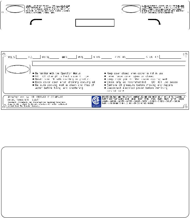
COVER CLOSED |
COVER OPEN |
DO NOT OPEN COVER |
MODEL 2400 |
UNLESS PRESSURE IS AT ZERO P.S.I. |
MANUFACTURED BY THE BROASTER COMPANY |
Item 1 - Part #15724
SAFETY AND OPERATING INSTRUCTIONS
FAILURE TO COMPLY WITH THESE SAFETY AND OPERATING INSTRUCTIONS COULD CAUSE INJURY TO OPERATOR AND BYSTANDERS.
MAXIMUM WORKING
PRESSURE 15 PSI
MADE IN U.S.A.
Item 2 - Part #11027
OPERATING INSTRUCTIONS
START UP
YOU ARE NOT REQURIED TO PHYSICALLY LIGHT THE PILOT ON THIS UNIT.
1.TURN THE MANUAL SHUT-OFF VALVE TO THE "ON" POSITION. WAIT 5 MINUTES BEFORE TURNING GAS VALVE ON.
2.MOVE SLIDE SWITCH ON GAS VALVE TO "ON"
3.MOVE COOK / FILTER SWITCH TO THE "COOK" POSITION.
SHUT DOWN
1.TURN COOK / FILTER SWITCH TO "OFF" POSITION.
2.MOVE SLIDE SWITCH ON GAS VALVE TO "OFF".
3.TURN THE MANUAL SHUT-OFF VALVE TO THE "OFF" POSITION.
INSTALL IN ACCORDANCE WITH AMERICAN NATIONAL STANDARD FUEL GAS CODE ANSI Z223. 1 LASTEST ADDITION
Item 3 - Part #15694
2400GH Only
1-2
broaster.com Manual #15460 8/02 Rev 7/14
MODEL 2400G
Item 6 - Part #11028
Item 4 - Part #15667
2400GH Only
Item 7 - Part #06375
CAUTION
Item 5 - Part #10900
Item 8 - Part #15725
CAUTION: DO NOT OPERATE THIS FRYER WITHOUT FILTER PAN & CLEAN COVER IN PLACE 
Item 9 - Part #15785
Item 10 - Part #16368 |
Item 11 - Part #11746 |
1-3
broaster.com Manual #15460 8/02 Rev 7/14
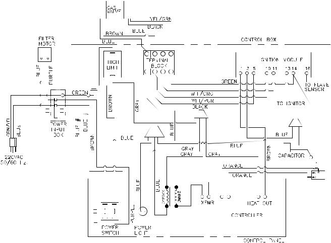
2 - ELECTRIC POWER SUPPLY
The 2400E is designed to operate on 3-phase input
ONLY. DO NOT connect to 1-phase power.
Many sections in this manual pertain to check-
ing and repairing electrical components. High voltage will be encountered in several instances. Only persons trained and equipped for checking high voltage shall undertake such repairs.
If no component operates, check main power supply. Be sure main circuit breaker is ON and main fuses are good.
Correct voltage: |
|
1-Phase |
|
2400GH |
120 VAC |
2400GH Export |
220 VAC |
3-Phase |
|
2400E |
208 or 240 VAC |
2400E Export & CE |
220/380 VAC |
|
220/415 VAC |
Perform the following if unit will not turn on:
1.Disconnect main power supply.
2.Be sure all connections are tight. If power supply is proper, see TROUBLESHOOTING section.
Wiring diagrams are located on inside front panel.
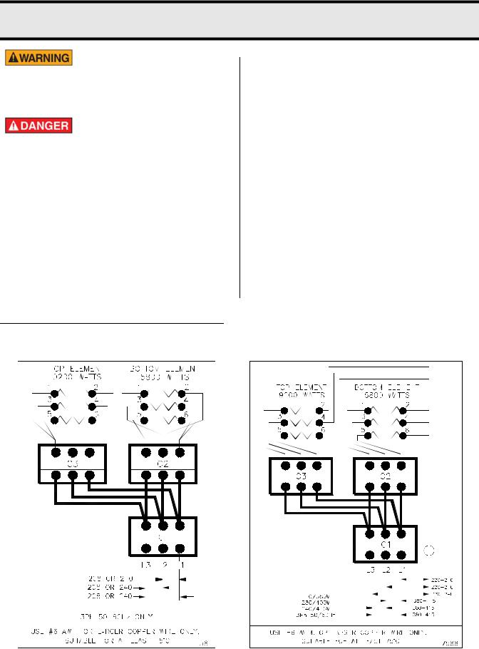
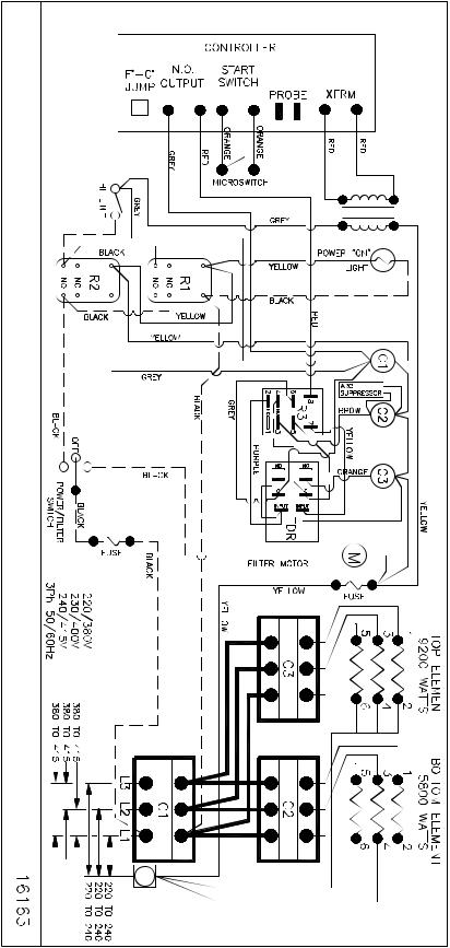
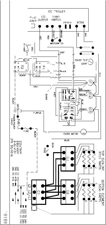
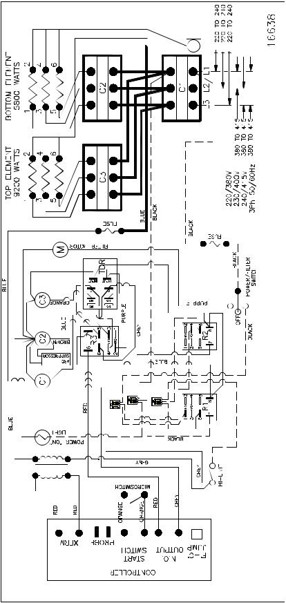
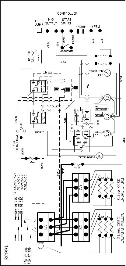
WIRING DIAGRAMS:
2400E DOMESTIC |
2400E EXPORT |
2-1
broaster.com Manual #15460 8/02 Rev 6/15
2400E 208 or 240VAC:
THE |
|
.CO BROASTER |
MODEL |
BELOIT, |
2400E |
WI |
|
53511 |
|
USE |
4 |
6 |
3 |
4 |
6 |
3 |
#6 |
2 |
5 |
1 |
2 |
5 |
1 |
.AWM |
|
|
|
|
|
|
OR |
|
|
|
|
|
|
.ONLY WIRE COPPER LARGER |
|
|
|
|
|
|
75°C LEAST AT FOR SUITABLE |
|
|
|
|
|
|
A 
 B
B
2-2
broaster.com Manual #15460 8/02 Rev 7/14

2400E 208 or 240VAC: Effective SE4A700011 |
|
|
|
|
|
75°C |
|
|
|
AT LEAST |
|
|
|
SUITABLE FOR |
|
|
|
WIRE ONLY. |
|
B |
A |
COPPER |
|
|
|
||
|
|
LARGER |
|
|
|
OR |
|
|
|
AWM. |
|
|
|
#6 |
|
|
|
USE |
|
|
|
|
WI 53511 |
|
|
2400E |
BELOIT, |
|
|
MODEL |
BROASTER CO. |
|
|
|
THE |
|
2-3 |
|
|
broaster.com |
Manual #15460 8/02 |
Rev 7/14 |
|
EXPORT: 2400EXP: 220/380 VAC to 240/415 VAC:
THE |
|
BELOIT, .CO BROASTER |
2400EXP MODEL |
WI |
|
53511 |
|
USE |
|
|
|
|
|
|
#6 |
2 4 |
5 6 |
1 |
2 4 |
5 6 |
1 3 |
.AWM |
|
|
|
|
|
|
OR |
|
|
|
|
|
|
LARGER |
|
|
|
|
|
|
COPPER |
|
|
|
|
|
|
WIRE |
|
|
|
|
|
|
.ONLY |
|
|
|
|
|
|
SUITABLE |
|
|
|
|
|
|
AT FOR |
|
|
|
|
|
|
LEAST |
|
|
|
|
|
|
75°C |
|
|
|
|
|
|
|
|
|
|
N |
|
|
A 
 B
B
2-4
broaster.com Manual #15460 8/02 Rev 7/14

EXPORT: 2400EXP: 220/380 VAC to 240/415 VAC: Effective SE4A700011
|
|
N |
|
|
|
|
LEAST 75°C |
|
|
|
SUITABLE FOR AT |
|
|
|
WIRE ONLY. |
B |
A |
|
LARGER COPPER |
|
|
|
|
|
|
|
#6 AWM. OR |
|
|
|
USE |
|
|
|
53511 |
|
|
|
WI |
|
|
MODEL 2400EXP |
BROASTER CO. BELOIT, |
|
|
|
THE |
|
2-5 |
|
|
broaster.com |
Manual #15460 8/02 |
Rev 7/14 |
|
EU: 2400ECE 220/380VAC to 240/415VAC:
THE |
|
|
|
|
|
|
BELOIT, .CO BROASTER |
2400ECE MODEL |
|
|
|
|
|
53511 WI |
|
|
|
|
|
|
USE |
4 |
6 |
3 |
4 |
6 |
3 |
#6 |
2 |
5 |
1 |
2 |
5 |
1 |
.AWM |
|
|
|
|
|
|
.ONLY WIRE COPPER LARGER OR |
|
|
|
|
|
|
75°C LEAST AT FOR SUITABLE |
|
|
|
|
|
|
A 

 B
B
2-6
broaster.com Manual #15460 8/02 Rev 7/14
EU: 2400ECE 220/380VAC to 240/415VAC: Effective SE4A700011
 N
N


B |
A |
2-7
|
AT LEAST 75°C |
|
SUITABLE FOR |
|
ONLY. |
|
OR LARGER COPPER WIRE |
|
USE #6 AWM. |
|
53511 |
|
WI |
MODEL 2400ECE |
BROASTER CO. BELOIT, |
|
THE |
broaster.com Manual #15460 8/02 Rev 7/14
EU: 2400ECE 220/380VAC to 240/415VAC: Effective SE4F310031
THE |
|
BELOIT, .CO BROASTER |
2400ECE MODEL |
WI |
|
53511 |
|
USE |
|
.AWM #6 |
|
WIRE COPPER LARGER OR |
|
.ONLY |
|
LEAST AT FOR SUITABLE |
|
75°C |
|
A 
 B
B
 N
N
2-8
broaster.com Manual #15460 8/02 Rev 7/14
MODEL 2400GH: DOMESTIC
MODEL 2400GHXP: EXPORT
2-9
broaster.com Manual #15460 8/02 Rev 7/14
MODEL 2400GHCE: EU

 2
2


 2
2


 1
1

 1
1


 1
1

 2
2
2-10
broaster.com Manual #15460 8/02 Rev 7/14
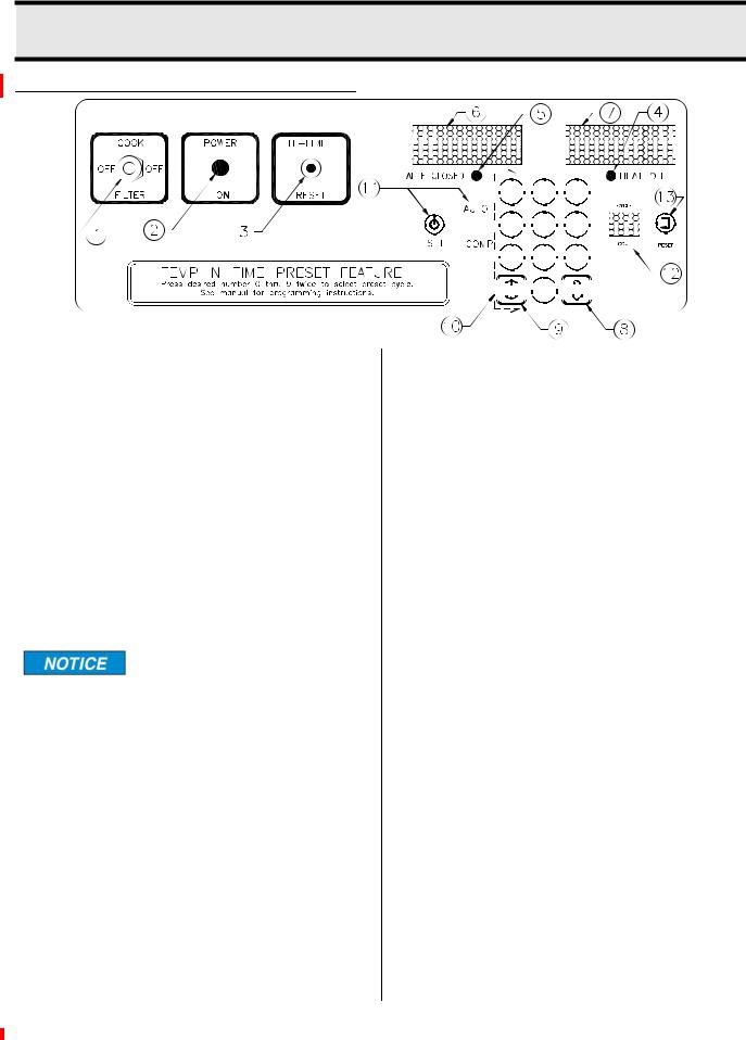
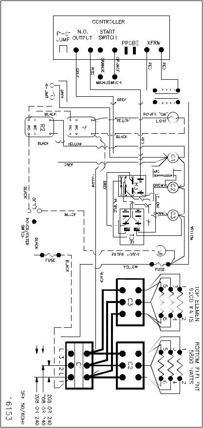
3 - CONTROL PANEL
TEMP-N-TIME FAMILIARIZATION
CAUTION!CHECK OIL LEVEL BEFORE OPERATING

 1
1 
 2
2 
 3
3 


 4
4 
 5
5 
 6
6 

 7
7 
 8
8 
 9
9 


 0
0


1.Cook/Filter Switch: Has three positions: COOK, OFF and FILTER.
2.Power On indicator Light: Illuminates when cook/filter switch is in COOK position.
3.Hi-Limit Control: Prevents oil temperature from exceeding 475°F. If power to unit turns off due to Hi-Limit Control, turn unit OFF and DO NOT attempt to operate until it has been serviced by an authorized Broaster Company representative.
It is possible for this control to trip during ship-
ment. If it does, fully depress red reset button. If control “clicks” it was tripped. If not, it is correctly reset.
4.Heat On Indicator Light: Illuminates when oil is being heated.
5.Valve Closed Indicator Light: Illuminates when pressure regulating valve is CLOSED.
6.Time Display: Shows time countdown during a cook cycle, program values during programming and programmed time during idle period.
7.Temp Display: Shows set temperature and actual temperature on demand.
8.Cook Temperature Button: Initiates temperature programming and display actual temperature.
9.Cook Time Button: Initiates time programming.
10.Numerical Keypad: Enters and adjusts set point values.
11.AUTO COMP (Automatic Time Compensation) Set Button and Light:
Indicates timing method. When OFF, controller operates as a regular timer. When ON, controller monitors oil temperature and adjusts time down rate to compensate for fluctuations in the oil temperature.
12.Cycle Count Display: Increases in increments of one every time a cooking cycle is completed.
13.Cycle Count Reset Button: Resets the cycle count display to “zero”.
3-1
broaster.com Manual #15460 8/02 Rev 6/16

CONTROLLER PROGRAMMING
Check oil level before turning cook/filter switch to COOK.
NORMAL OPERATING MODE
Action: Turn cook/filter switch to COOK.
Response: Temp Display alternates between number values for cook temperature, and LO (idle mode). LO will disappear when oil temperature has reached cook temperature value. Time Display will show the set time in minutes and seconds.
Set Temperature:
Action: Press Cook Temperature Button twice within 5 seconds.
Response: Programming mode has been entered. Flashing Temp Display reads “###F.” (### = temperature value ie: 360F)
Action: If desired, press keypad numbers to change displayed value. Press Cook Temperature Button once to enter new value into memory.
Response: Controller returns to idle mode.
Set Time:
Action: Press Cook Time Button twice within 5 seconds.
Response: Programming mode has been entered. Flashing Time Display reads “##:##.” (##:## = time value ie: 08:00)
Action: If desired, press key pad numbers to change displayed value in minutes and seconds. Press Cook Time Button once to enter new value into memory.
Response: Controller returns to idle mode.
Set AUTO COMP (Automatic Time Compensation):
Action: Press and hold AUTO COMP Button for 3 seconds.
Response: Green light will toggle on or off.
Display Actual Temperature:
Action: Press and hold Temp Button for 3 seconds.
Response: Temp Display will show actual oil temperature and will vary as cooling and heating takes place.
Action: Press Temp Button to return to set point display.
Reset Cycle Counter:
Action: Press Reset Button twice in 5 seconds.
Response: Display will return to a setting of “00.”
If counter is not reset before reaching “99”.
Upon the next cycle completion, the display will begin counting at “01”.
Normal operating programming can be done at any time without affecting presets.
3-2
broaster.com Manual #15460 8/02 Rev 6/16

PRESET COOK MODE
PROGRAMMING METHOD 1
Choose Preset Cook Cycle:
Action: Press a button, 0 thru 9, corresponding to the desired preset.
Response: The TIME display will show “P__X”, where X is the preset selected.
If a button is not pressed in ten seconds, the dis-
play will revert to the previous display.
Action: Press the same button again,
Response: The TIME display will show the preset time, the AUTO COMP LED will turn on if enabled, the TEMP display will show the preset setpoint, and the temperature will now regulate to the new setpoint.
PROGRAMMING PROCEDURE (PRESET MODE)
Action: Press and hold the TIME and TEMP buttons simultaneously for three seconds.
Response: The TIME display and TEMP display will begin flashing. The CYCLE COUNT display will show “-0” indicating that the preset #0 values are displayed. The preset values for the TIME, TEMP, and AUTO COMP will be shown on the display.
Change Cook Time:
Action: Press the TIME button once.
Response: The TEMP display will turn off and only the TIME display will flash.
Action: Key in the desired cook time and press the TIME button to save the new setting.
If a button is not pressed in ten seconds, the dis-
play will revert back to both the TIME and TEMP displays flashing.
Change Cook Temperature:
Action: Press the TEMP button once.
Response: The TIME display will turn off and the TEMP display will be flashing.
Action: Key in the desired temperature setting and press the TEMP button to save the new setting.
If a button is not pressed in ten seconds, the dis-
play will revert back to both the TIME and TEMP displays flashing.
Activate/Deactivate Auto Comp:
Action: Press the AUTO COMP button once.
Response: AUTO COMP is enabled when the AUTO COMP LED is on and disabled when it is off.
Advance to Next Preset:
Action: Press the RESET button once.
Response: The CYCLE COUNT display will change to “-1” and the presets for #1 will be displayed.
Repeat the process as described. After the presets for #9 are displayed, pressing the RESET button again will cause the control to return to normal operation.
3-3
broaster.com Manual #15460 8/02 Rev 6/16

PRESET COOK MODE PROGRAMMING METHOD 2
Select the temperature and time, following the normal programming procedure. To save these settings for a preset. Press and hold the desired preset number for five seconds until an audible beep is sounded.
WARNING DISPLAYS
HI - Display will flash HI if cooking oil temperature exceeds 415°F. Audible alert will sound until cook/filter switch is turned OFF or hi-limit trips. All controller functions and heat source are disabled during this condition.
Cause: Faulty controller, gas valve (2400GH Only) of contactor (2400E Only).
PROB - Display will flash PROB if there is a problem with temperature sensor probe. Audible alert will sound until cook/filter switch is turned OFF. All controller functions and heat source are disabled during this condition.
Cause: Temperature sensor prove faulty, polarity of probe wires reversed or probe wire(s) loose.
CHEC - Display will flash CHEC if cooking oil temperature does not rise 6°F within the first three minutes. Audible alert will sound until cook/filter switch is turned OFF. All controller functions and heat source are disabled during this condition.
Cause: Faulty controller, heating element(s) (2400E Only) gas valve (2400GH Only), contactor (2400E Only), probe or loose wiring.
CHEC could appear if cooking oil temperature is
below 45°F. Turn cook/filter switch OFF then to COOK for another three minute heating period. This may have to be repeated two or three times.
FAIL - Display will flash FAIL if controller detects a fault within itself. Audible alert will sound until cook/filter switch is turned OFF. All controller functions and heat source are disabled during this condition.
Cause: Faulty controller.
3-4
broaster.com Manual #15460 8/02 Rev 6/16

DISPLAY ACTUAL TEMPERATURE
Action: Press and hold cook temperature button for three seconds.
Response: Display will show actual temperature and will vary as cooling and heating takes place.
Action: Press cook temperature button again to return to idle mode.
CALIBRATION
Calibration will be necessary when temperature sensor probe or controller is replaced. Calibrate using an accurate non-mercury test thermometer.
1.Thoroughly heat cooking oil. When HEAT ON light goes out, stir oil. If HEAT ON light comes on allow unit to recover until light goes out. This may have to be done several times.
2.Press and hold cook temperature button for ten seconds until OFF then SET is displayed twice. Release button.
3.Uncalibrated cooking oil temperature is displayed. Calibration must be performed.
4.Check cooking oil temperature one inch below oil surface in the center of cooking well.
5.Using keypad, enter temperature to match controller display with calibrating thermometer.
6.Press temp button to exit calibration.
3-5
broaster.com Manual #15460 8/02 Rev 6/16
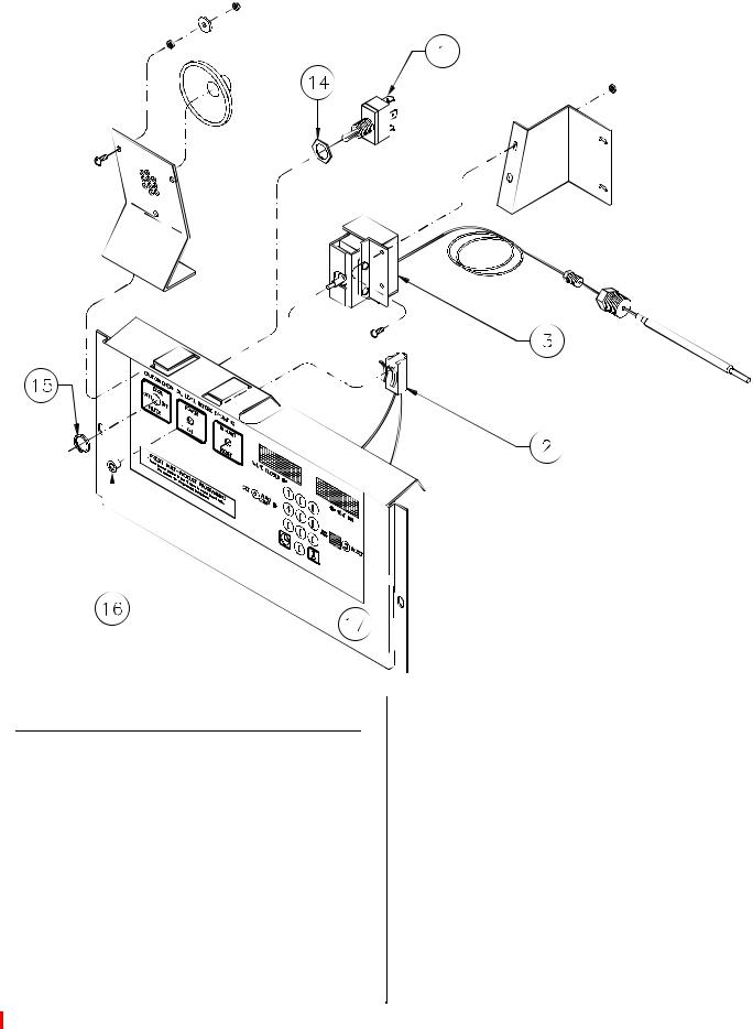
ACCESS FOR SERVICE
1.Disconnect main power supply.
2.Remove condensate pan and screws from bottom of front panel. Pull out and remove front panel.
3.Remove screws holding controller (17) to the power input box. Tilt panel down so back is visible.
3-6
broaster.com Manual #15460 8/02 Rev 7/14
 Loading...