

Page 1
RANGE AoST oR
RM60000 SERIES
RANGE HOOD
INSTALLATION INSTRUCTIONS
AND USER MANUAL
HBO026
Z_INTENDED FOR RESIDENTIAL USE ONLY/_
_,,1=lr_,_my_,_#Im]l,.,-t!'_,\,A=ll iI-=I =[,,.1=mi#_ / [_|[_ / [o] #_
INSTALLER: LEAVE THIS MANUAL WITH HOMEOWNER.
HOMEOWNER: USE AND CARE INFORMATION ON PAGE 10.
Broan-NuTone LLC, 926 West State Street, Hartford, Wl 53027 (1-800-637-!453)
NuTone, Inc., 4820 Red Bank Road, Cincinnati, OH 45227 (1-800-543-8687)
Broan-NuTone Canada, Inc., 1140 Tristar Drive, Mississauga, ON L5T 1H9 (!-888-882-7626)
V05527 rev. D
Page 2
WARNING WARNING
TO REDUCE THE RISK OF FIRE, ELECTRIC SHOCK OR
INJURY TO PERSONS, OBSERVE THE FOLLOWING:
1. Use this unit only in the manner intended by the
manufacturer, tf you have questions, contact the
manufacturer at the address or telephone number
listed in the warranty.
2. Before servicing or cleaning unit, switch power off at
service panel and lock service disconnecting means
to prevent power from being switched on accidentally.
When the service disconnecting means cannot be
locked, securely fasten a prominent warning device,
such as a tag, to the service panel.
3. Installation work and electrical wiring must be
done by qualified personnel in accordance with
all applicable codes and standards, including
fire-rated construction codes and standards.
.
Sufficient air is needed for proper combustion and
exhausting of gases through the flue (chimney) of
fuel burning equipment to prevent backdrafting.
Follow the heating equipment manufacturer's
guidelines and safety standards such as those
published by the National Fire Protection
Association (NFPA), and the American Society for
Heating, Refrigeration and Air Conditioning
Engineers (ASHRAE), and the local code authorities.
5. When cutting or drilling into wall or ceiling, do not
damage electrical wiring and other hidden utilities.
6. Ducted fans must always be vented to the outdoors.
7. Do not use this unit with any additional solid-state
speed control device.
8. To reduce the risk of fire, use only steel ductwork.
9. This unit must be grounded.
TO REDUCE THE RISK OF A RANGE TOP GREASE
FIRE:
a) Never leave surface units unattended at high
settings. Boilovers cause smoking and greasy
spillovers that may ignite. Heat oils slowly on low or
medium settings.
b) Always turn hood ON when cooking at high heat or
when cooking flaming foods.
c) Clean ventilating fans frequently. Grease should not
be allowed to accumulate on fan or filter.
d) Use proper pan size. Always use cookware
appropriate for the size of the surface element.
TO REDUCE THE RISK OF INJURY TO PERSONS IN
THE EVENT OF A RANGE TOP GREASE FIRE,
OBSERVE THE FOLLOWING*:
SMOTHER FLAMES with a close-fitting lid,
cookie sheet or metal tray, then turn off the
burner. BE CAREFUL TO PREVENT BURNS.
IF THE FLAMES DO NOT GO OUT IMMEDIATELY,
EVACUATE AND CALL THE FIRE DEPARTMENT.
2. NEVER PICK UP A FLAMING PAN - You may
be burned.
3. DO NOT USE WATER, including wet dishcloths or
towels - This could cause a violent steam explosion.
.
Use an extinguisher ONLY if:
A. You own a Class ABC extinguisher and
you know how to operate it.
B. The fire is small and contained in the area
where it started.
C. The fire department has been called.
D. You can fight the fire with your back to an exit.
* Based on "Kitchen Fire Safety Tips" published by NFPA.
CAUTION
1. For general ventilating use only. Do not use to
exhaust hazardous or explosive materials and
vapors.
2. To avoid motor bearing damage and noisy
and/or unbalanced impellers, keep drywall
spray, construction dust, etc. off power unit.
.
Your hood motor has a thermal overload which
will automatically shut off the motor if it
becomes overheated. The motor will restart when
it will be cooled down. If the motor continues
to shut off and restart, have the hood serviced.
.
For best capture of cooking impurities, the bottom of
the hood should be at a minimum of 24" and at a
maximum of 30" above the cooking surface.
5. To reduce the risk of fire and to properly
exhaust air, be sure to duct air outside - Do not
exhaust air into spaces within walls or ceilings
or into attics, crawl spaces or garage.
6. This product is equipped with a thermostat which
may start blower automatically. To reduce the
risk of injury and to prevent power from being
switched on accidentally, switch power off at service
panel and lock or tag service panel.
7. To reduce the risk of fire and electrical shock, the
Rangemaster RM60000 Series hood must be
installed with blower models RM325H, RM326H,
331 H, 332H, 335 or 336 only. Other blowers cannot
be substituted. (Blowers sold separately).
8. Use with approved cord-connection kit only.
9. Please read specification label on product for
further information and requirements.
-2-
Page 3
1,0
2,0
3,0
4,0
5,0
6,0
7,0
8,0
9,0
10,0
11,0
12,0
13,0
14,0
15,0
16,0
17,0
18,0
SELECT BLOWER OPTION AND iNSTALL DUCTWORK ..................................... 5
MEASURE iNSTALLATiON ............................................................ 5
PREPARE THE INSTALLATION ......................................................... 6
INSTALL BACKSPLASH ............................................................... 6
INSTALL WOOD MOUNTHNG STRHP ..................................................... 6
INSTALL THE HOOD ................................................................. 6
INSTALL TRANSHTHON TO ROUGH-HN PLATE .............................................. 7
INSTALL THE ROUGH-HN PLATE TO THE HOOD ........................................... 7
CONNECT THE WHRHNG .............................................................. 7
WHRHNGDHAGRAM .................................................................. 8
INSTALL THE OPTHONAL SOFFHT CHHMNEY .............................................. 8
INSTALL BLOWER .................................................................. 8
INSTALL LHGHT BULBS AND WARMING LAMPS ........................................... 8
INSTALL FILTERS ................................................................... 9
USE AND CARE .................................................................... 10
OPERATION ....................................................................... 10
SERVHCE PARTS .................................................................... 11
WARRANTY ....................................................................... 12
-3-
Page 4
Waft & Roof
Caps, ExL
Blowers
Elbows &
In-Line
Dampers
Ductwork
MODEL 331R M_ 335 MODEL 437 MODEL 441
(600 cfm) OR (1200 cfm) OR (High Capacity (10" Rd.
332R (900 cfm) 336 (1500 cfm) Roof Cap) Wall Cap)
(Exterior Blower) (Exterior Blower) i
I ' i
L..................... _7ZTZTZTZ_"--ITIZLZIZZZZZ_-..................... J
i i i
i z
MODEL 647
(7" Rd.
Wall Cap)
MODEL 418 MODEL 421 MODEL 415
(10" Rd. Adjustable Elbow) (10' Rd. Vert. (7' Rd. Adjustable Elbow)
\ I
\ // i
\ / i
\ /
\
\ / I
\ / i
\ /
\ / !
In-Line Damper) !
MODEL 410 MODEL 407
(10" Rd, Duct - 2 ft. sections) (7" Rd, Duct - 2 ft, sections)
\v/
/
/
1
/
MODEL 634
OR 644
(Roof Cap)
/
z /
Choose 1 of
5 Discharge
7?ansitions
Choose 1 of 3
Blower Systems
MODEL 427
(4Vd x 18W'
to 10" Rd., 6'
high - lateral)
ROUGH-IN }<IT
MODEL 332KR
(Use with all
Exterior Blower
models: 331H,
332H, 335,336)
.... - T i ! .......... q.........................
I I I
i i
MODEL 423
(4W' x 181/2"to (41/2" x 18Vd' to (41/d' x 181/#' to (4Vd' x 181/2"to
10" Rd, - vertical) i 0" Rd.- horiz. 10" Rd. - 10" Rd.- horiz./
I
MODEL 424 MODEL 454 MODEL 453 I
front / rear) horiz, / right) left) I
L................... J ....................... J ....................... L ..................... J
_ONAL SOFFIT
i CHIMNEY
i RMN SERIES
i
i
I
\\ RM6O0O0
MODEL RM326R
BLOWER / ROUGH:IN }(IT
(1200 cfm Interior Blower &
Rough-in Plate)
\ SERIES '_
(Canopy with
blower controls
& lighting.
Required for all OPTIONAL
instaNations.) BAFFLE
MODEL RM325R
BLOWER / ROUGH-iN KIT
-_ ......... _ Rough-in Plate)
(600 cfm Interior Blower &
HOOD
FILTERS
RRF SERIES
BY BROAN NUTONE
RM60000 SERIES
RANGE HOOD SYSTEM
=4 =
RMP SERIES BACKSPLASR
(Stainless Steel wall covering
with warming shelves. Optional)
HLO030
Page 5
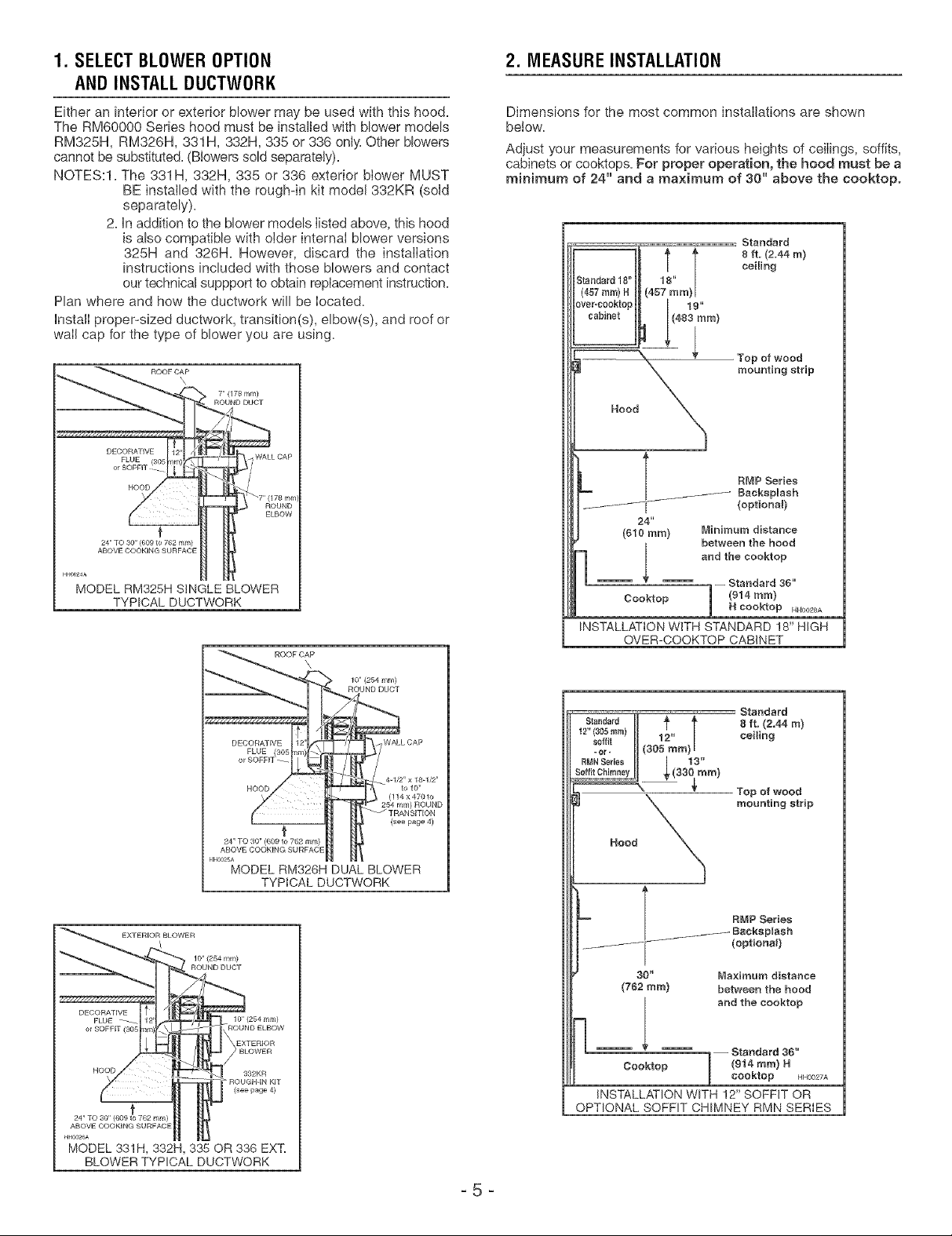
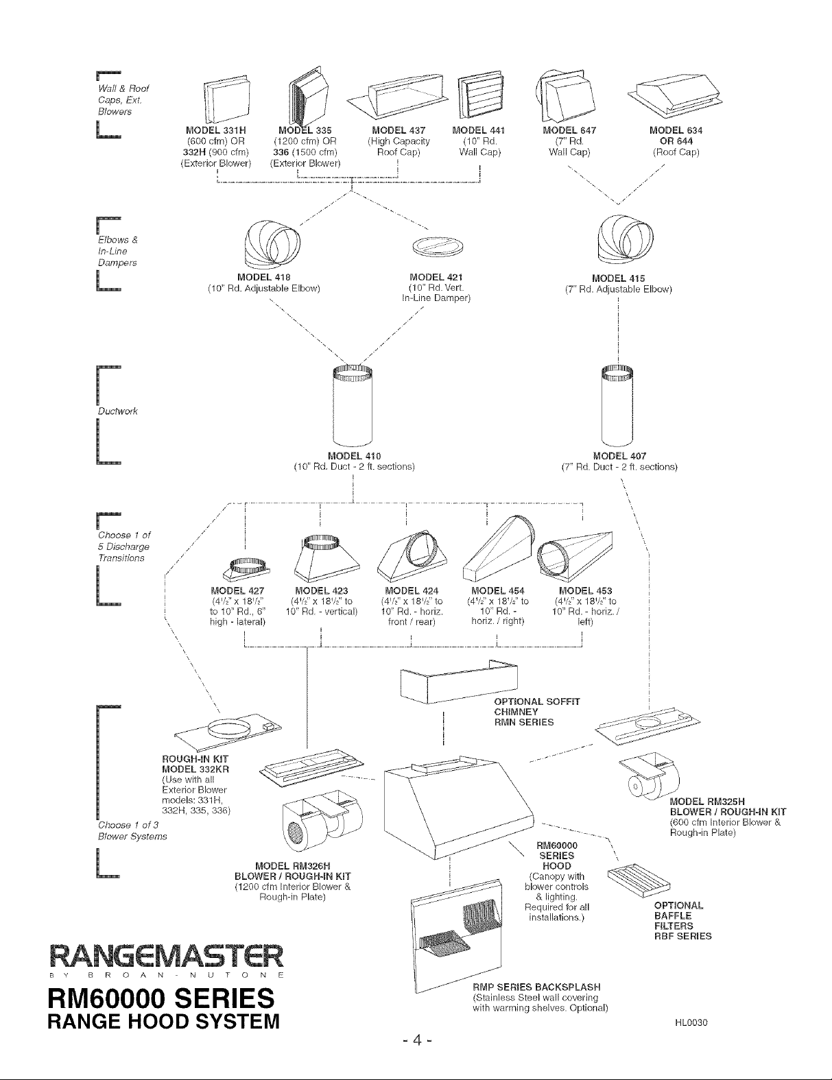
1. SELECTBLOWER OPTION
AND INSTALL DUCTWORK
2. MEASUREINSTALLATION
Either an interior or exterior blower may be used with this hood.
The RM60000 Series hood must be installed with blower models
RM325H, RM326H, 331H, 332H, 335 or 336 only. Other blowers
cannot be substituted. (Blowers sold separately).
NOTES:I. The 331 H, 332H, 335 or 336 exterior blower MUST
BE installed with the rough-in kit model 332KR (sold
separately).
2. in addition to the blower models listed above, this hood
is also compatible with older internal blower versions
325H and 326H. However, discard the installation
instructions included with those blowers and contact
our technical suppport to obtain replacement instruction.
Plan where and how the ductwork will be located.
install proper-sized ductwork, transition(s), elbow(s), and roof or
wail cap for the type of blower you are using.
711(178 mm)
Dimensions for the most common installations are shown
below.
Adjust your measurements for various heights of ceilings, soffits,
cabinets or cooktops. For proper operation, the hood must be a
minimum of 24" and a maximum of 30" above the cooktop.
Standard 18" 18"
(457rnm)H (457 ram)
over'c0okto9 19"
cabinet (483 ram)
Top of wood
mounting strip
RMR Series
--_ BackspUash
24"
({}10 ram) Minimum distance
(optiona0
between the hood
MODEL RM328H SINGLE BLOWER
TYPICAL DUCTWORK
MODEL RM326H DUAL BLOWER
TYPICAL DUCTWORK
10" (254 mill)
10" (254 mm)
BLOWER
ROOFCAP
f
and the eooktop
-- Starldard 36"
Cooktop H cooktop HHOO2SA
(914 ram}
INSTALLATION WITH STANDARD !8" HIGH
OVER-COOKTOP CABINET
\
le'(254 mm)
ROUND DUCT
Stasdard
8 ft. (2,44 m)
ceiling
(33 ram)
(114 x470to
(see page 4)
._ RNP Series
OPTIONAL SOFFIT CHIMNEY RMN SERIES
\ Top of wood
X mounting strip
Hood
_- IBacksplash
30" Maximum distance
(762 tara) between the hood
Cooktop m (914 tara) H
(optional)
and the cooktop
'1-- Standard 36"
j cooktop NH0027A
INSTALLATION WITH !2" SOFFIT OR
HH0026A
MODEL 331H, 332H, 338 OR 338 EXT.
BLOWERTYPICAL DUCTWORK
_5 _
Page 6
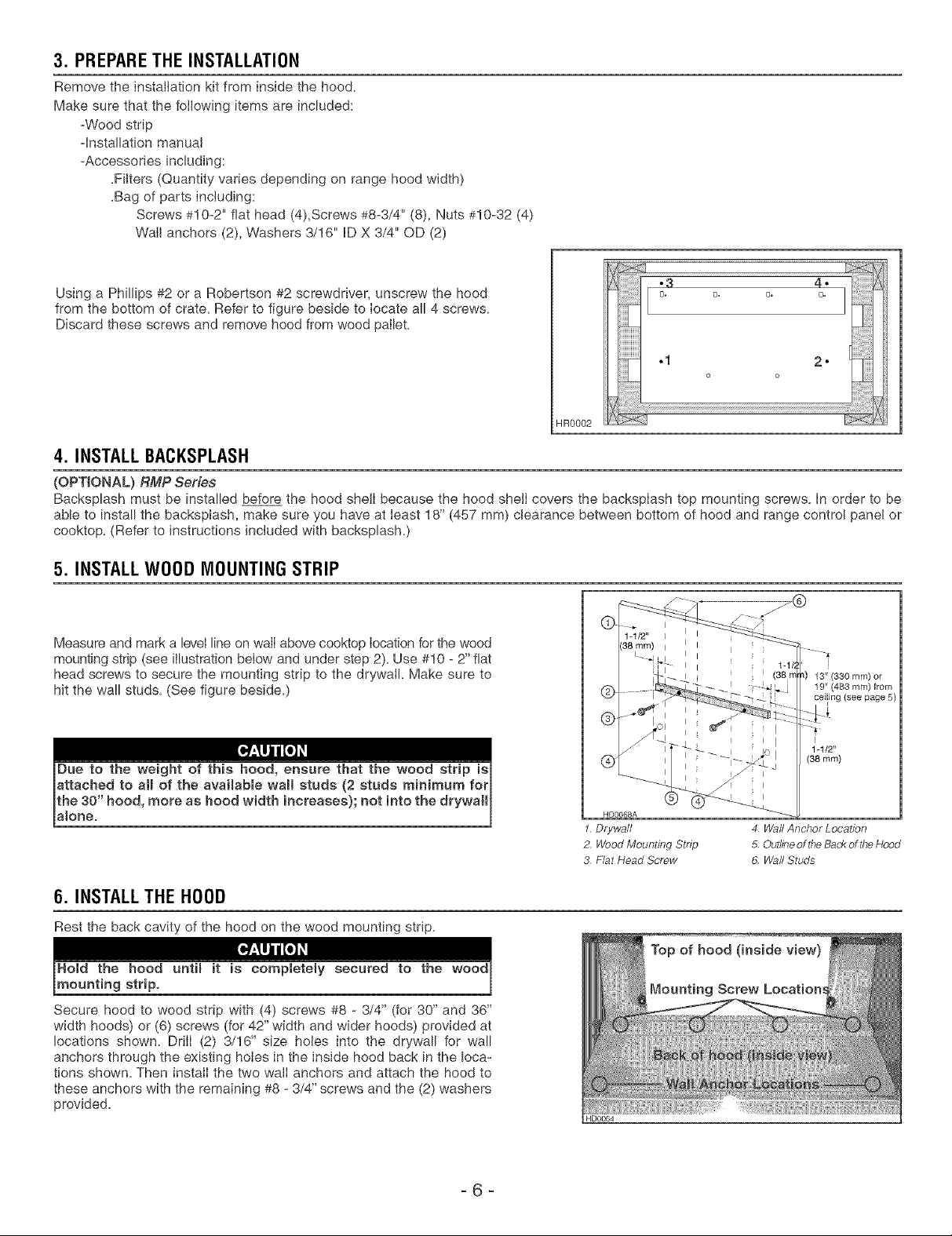
3. PREPARETHE INSTALLATION
Remove the installation kit from inside the hood.
Make sure that the fotlowing items are included:
+Wood strip
4nstallation manual
+Accessories including:
+Filters (Quantity varies depending on range hood width)
+Bag of parts inciud+ng:
Screws #10-2" flat head (4),Screws #8-3/4" (8), Nuts #10-32 (4)
Wail anchors (2), Washers 3/16" ID X 3/4" OD (2)
Using a Phillips #2 or a Robertson #2 screwdriver, unscrew the hood
from the bottom of crate. Refer to figure beside to locate all 4 screws.
Discard these screws and remove hood from wood pallet.
HR0002
4. INSTALLBACKSPLASH
(OPTIONAL) RMP Serfes
Backsplash must be installed before the hood shelI because the hood shelI covers the backspIash top mounting screws. In order to be
able to install the backsplash, make sure you have at least 18" (457 mm) clearance between bottom of hood and range control panel or
cooktop. (Refer to instructions included with backsplash.)
5. INSTALLWOOD MOUNTING STRIP
Measure and mark a level line on waiI above cooktop Iocation for the wood
mounting strip (see iilustration below and under step 2)+ Use #10 - 2" flat
head screws to secure the mounting strip to the drywall Make sure to
hit the wall studs. (See figure beside.)
6. INSTALLTHE HOOD
Rest the back cavity of the hood on the wood mounting strip.
Secure hood to wood strip with (4) screws #8 - 3/4" (for 30" and 36"
width hoods) or (6) screws (for 42" width and wider hoods) provided at
locations shown. Drill (2) 3/16" size holes into the drywall for wall
anchors through the existing hoies in the inside hood back in the loca-
tions shown. Then instaiI the two walI anchors and attach the hood to
these anchors with the remaining #8 +3/4" screws and the (2) washers
provided.
®
®
®
HDOO68A
1. Drywall
2. Wood Mounting Stnp
3 Flat Head Screw
13" (330 mm) or
19" (483 ram) from
ceiiing (see page 5)
(38 ram)
4 [A/allAnchor Location
5. Outline of the Back of the Hood
6. Wall Studs
Page 7
7. INSTALLTRANSITION TO ROUGH-IN PLATE
Model 423, 424, 427, 453, or 454
Attach transition (if required) to blower rough-in plate.
Use duct tape to make aII joints secure and air-tight.
NOTE: Model RM325H blower plate connects directly to 7" round ductwork
without a transition.
Exterior blower models utilize a mode! 332KR rough-in plate
which connects directly to 10" round ductwork without a transition.
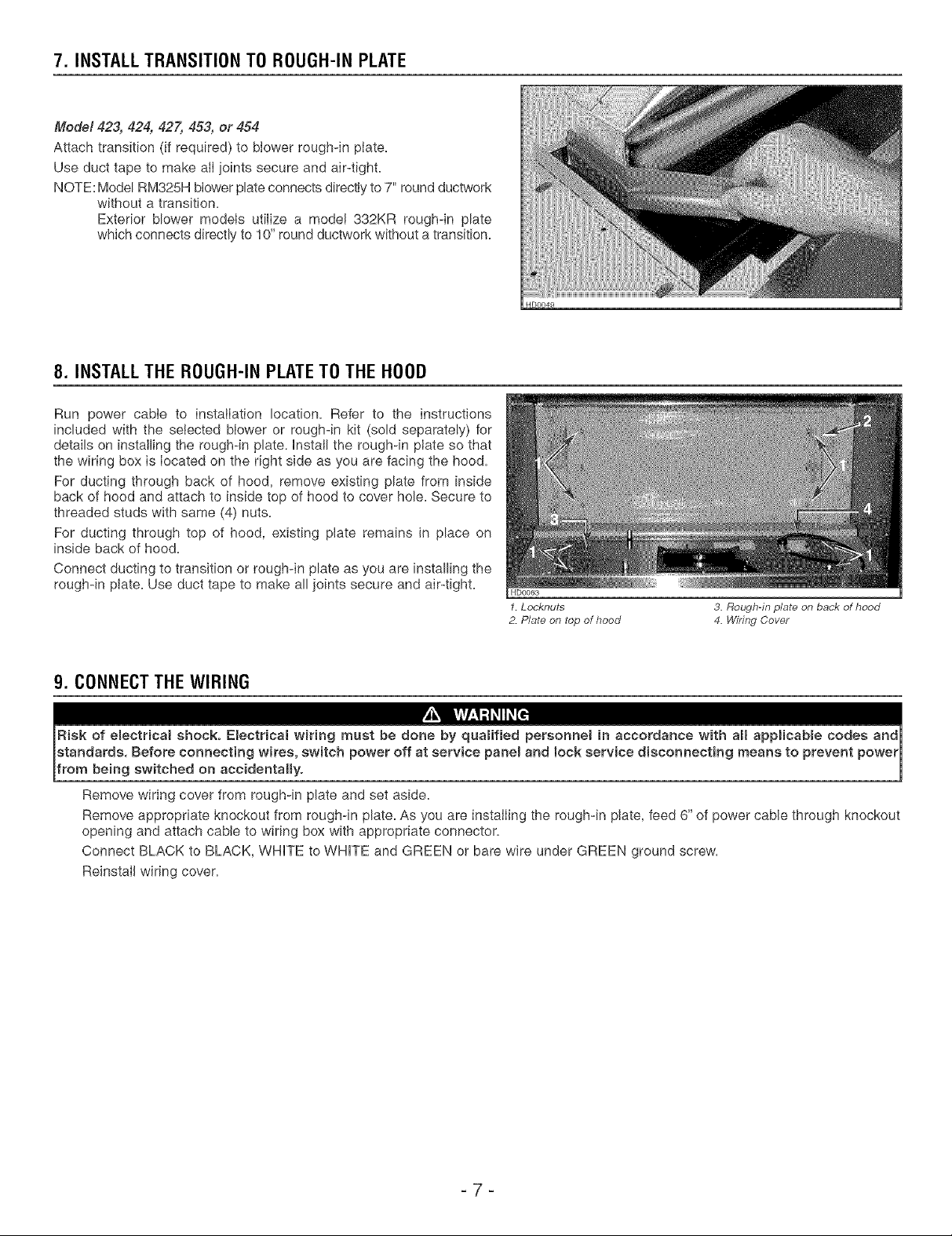
8. INSTALLTHE ROUGH-IN PLATETO THE HOOD
Run power cable to installation location. Refer to the instructions
included with the selected blower or rough-in kit (sold separately) for
details on installing the rough-in plate. Instatl the rough-in plate so that
the wiring box is located on the right side as you are facing the hood.
For ducting through back of hood, remove existing plate from inside
back of hood and attach to inside top of hood to cover hole. Secure to
threaded studs with same (4) nuts.
For ducting through top of hood, existing plate remains in place on
inside back of hood.
Connect ducting to transition or rough-in plate as you are installing the
rough-in plate. Use duct tape to make all joints secure and air-tight.
HDO063
1.Locknuts
2. Pluto on top of hood
3. Rough-in plate on back of hood
4. Wiring Cover
9. CONNECTTHE WIRING
Risk of eject with aH appHcabme codes andj
etandarde, Before connecting wires, switch power off at service panem and lock service disconnecting means to prevent powerJ
[from be ng ew tched on ace denta y. j
Remove wiring cover from rough-in plate and set aside.
Remove appropriate knockout from rough-in plate. As you are instalIing the rough-in plate, feed 6" of power cable through knockout
opening and attach cable to wiring box with appropriate connector.
Connect BLACK to BLACK, WHITE to WHITE and GREEN or bare wire under GREEN ground screw.
ReinstaII wiring cover.
H
_7 _
Page 8
10. WIRING DIAGRAM
RIGHT HEAT LAMP SWITCH
HE0018
11. INSTALLTHE OPTIONAL SOFFIT CHIMNEY
(OPTIONAL) RMN Series
Refer to the instructions included with the soffit chimne_
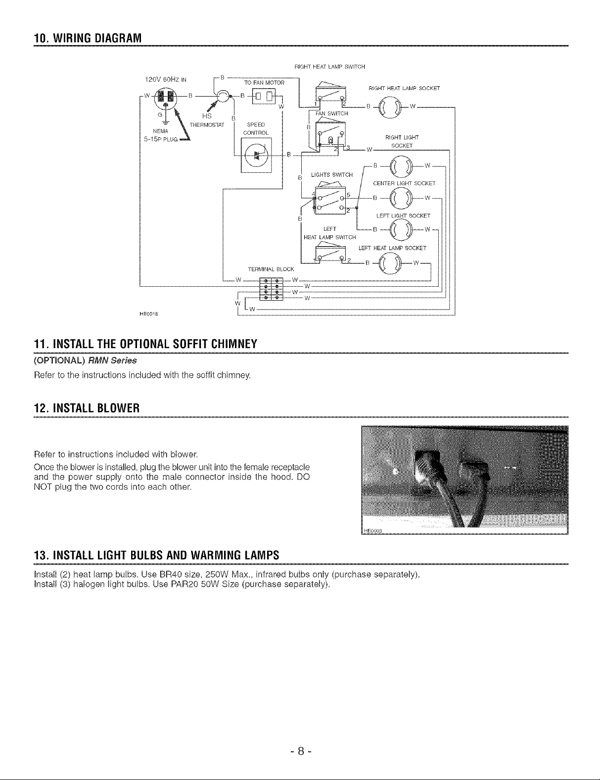
12. INSTALL BLOWER
Refer to instructions included with blower.
Once the blower is installed, plug the blower unit into the female receptacle
and the power supply onto the male connector inside the hood. DO
NOT plug the two cords into each other.
HE0003
13. INSTALL LIGHT BULBSAND WARMING LAMPS
InstalI (2) heat lamp bulbs. Use BR40 size, 250Vv' Max, infrared bulbs only (purchase separately).
Install (3) halogen light bulbs. Use PAR20 50W Size (purchase separately).
=8 =
Page 9
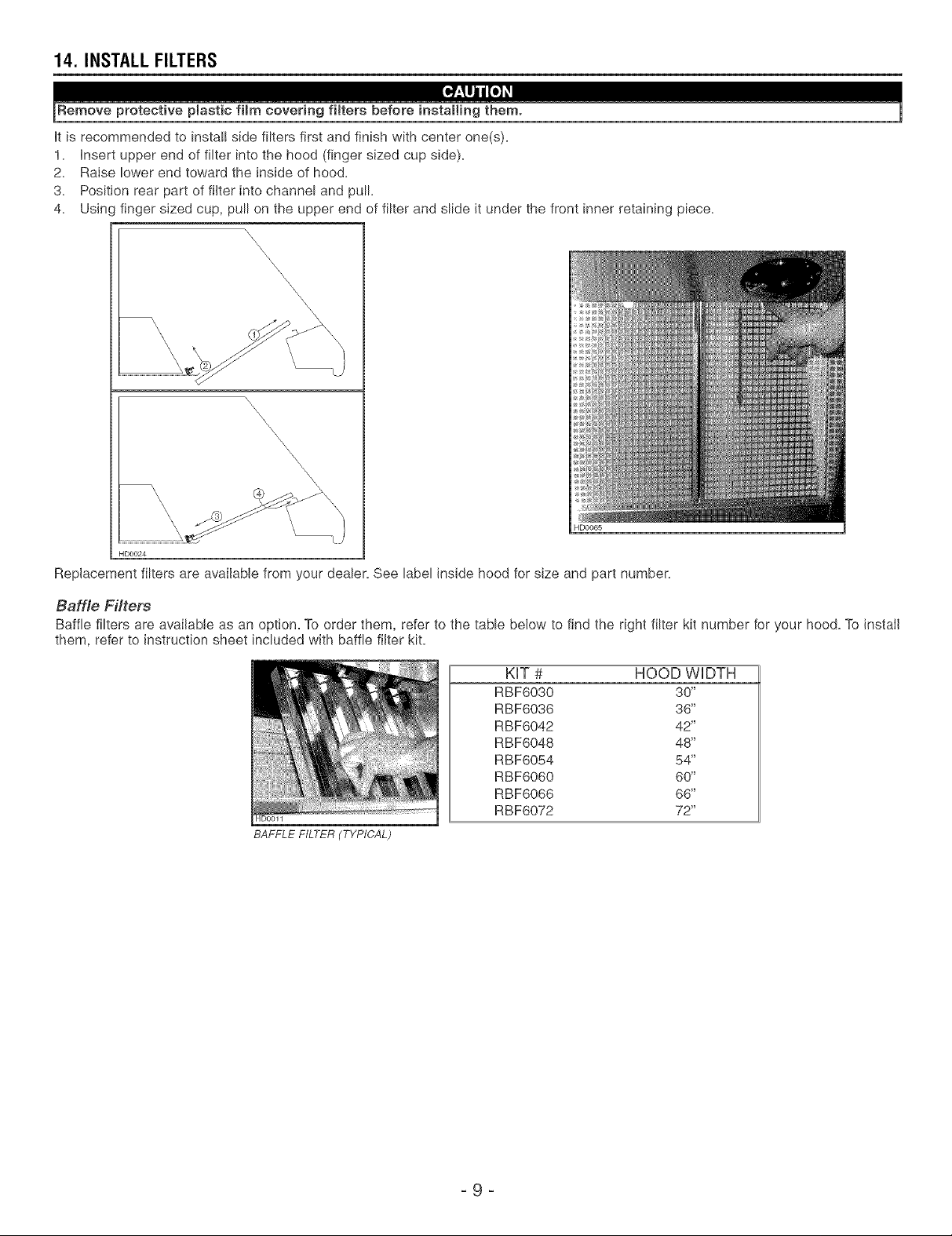
14. INSTALL FILTERS
It is recommended to instal! side filters first and finish with center one(s).
1. Insert upper end of filter into the hood (finger sized cup side).
2. Raise lower end toward the inside of hood.
3. Position rear part of filter into channel and pull.
4. Usin( finger sized cup, pull on the upper end of filter and slide it under the front inner retaining piece.
\\\\
\
\\\\\
HDO065
HD0024
Replacement filters are available from your dealer. See label inside hood for size and part number.
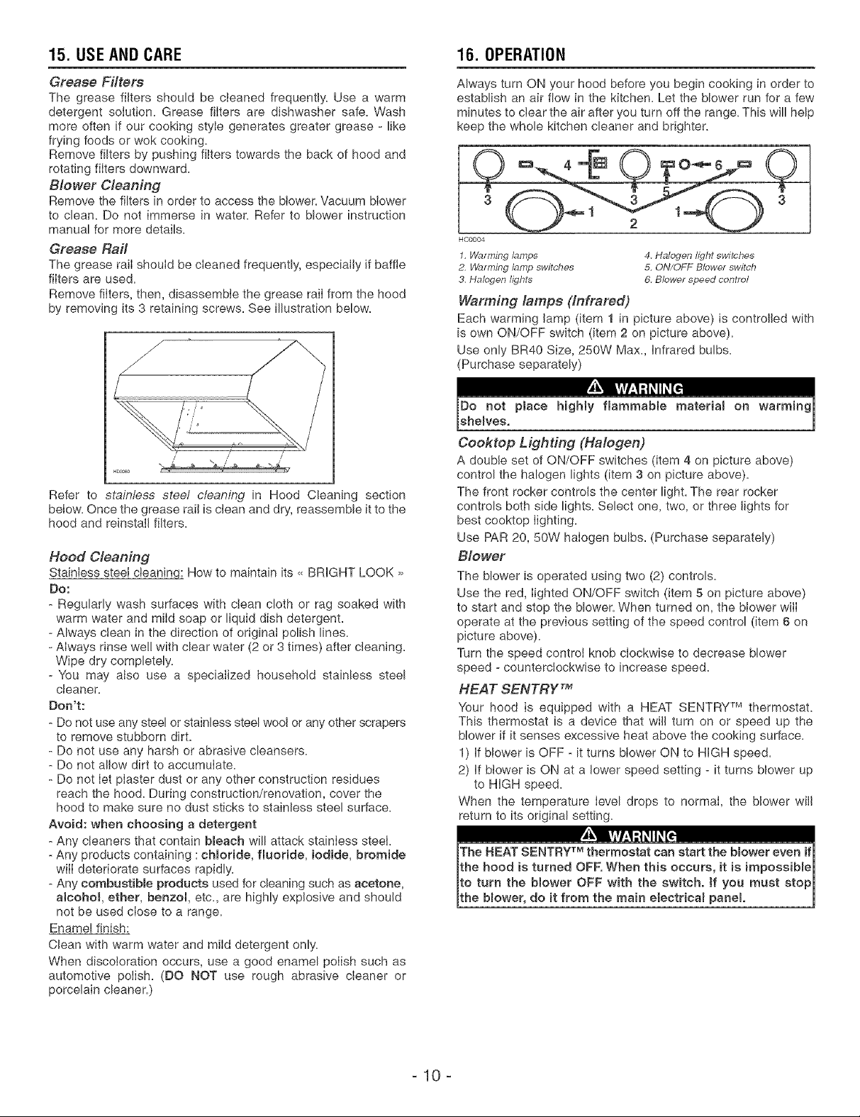
Baffle Filters
Baffle filters are available as an option_ To order them, refer to the table below to find the right filter kit number for your hoe& To install
them, refer to instruction sheet included with baffle filter kit.
KIT # HOOD WIDTH
RBF6030 30"
RBF6036 36"
RBF6042 42"
RBF6048 48"
RBF6054 54"
RBF6060 60"
RBF6066 66"
HD0011
BAFFLE FILTER (TYPICAL)
RBF6072 72"
_9 _
Page 10
15. USEAND CARE 16. OPERATION
Grease Filters
The grease filters should be cleaned frequently. Use a warm
detergent solution. Grease filters are dishwasher safe. Wash
more often if our cooking style generates greater grease - like
frying foods or wok cooking.
Remove filters by pushing filters towards the back of hood and
rotating filters downward.
Blower Cleaning
Remove the filters in order to access the blower. Vacuum blower
to clean. Do not immerse in water. Refer to blower instruction
manual for more details.
Grease Rail
The grease raiI shouId be cIeaned frequently, especiaIly if baffle
filters are used.
Remove filters, then, disassemble the grease raiI from the hood
by removing its 3 retaining screws. See illustration below.
Refer to stainless steel cteanit_g in Hood Cleaning section
below. Once the grease rail is clean and dry, reassemble it to the
hood and reinstalI filters.
Hood Cleaning
Stainless steel cteaningl How to maintain its ,, BRIGHT LOOK >>
Do:
- Regularly wash surfaces with clean cloth or rag soaked with
warm water and mild soap or liquid dish detergent.
- Always clean in the direction of original polish lines.
- Always rinse wel! with clear water (2 or 3 times) after cleaning.
Wipe dry completely.
- You may also use a specialized household stainless steel
cleaner.
Don't:
- Do not use any steel or stainless steel wool or any other scrapers
to remove stubborn dirt.
- Do not use any harsh or abrasive cleansers.
- Do not allow dirt to accumuIate.
- Do not Iet piaster dust or any other construction residues
reach the hood. During construction/renovation, cover the
hood to make sure no dust sticks to stainless steel surface.
Avoid: when choosing a detergent
- Any cleaners that contain b_each will attack stainIess steel.
- Any products containing :cHoride, fluoride, iodide, bromide
will deteriorate surfaces rapidly.
- Any combuetiMe products used for cleaning such as acetone,
atcohoL ether, benzol, etc., are highly explosive and should
not be used cIose to a range.
Enamel finish:
Clean with warm water and miId detergent only.
When discoloration occurs, use a good enamel poIish such as
automotive poIish. (DO NOT use rough abrasive cleaner or
porcelain cleaner.)
Always turn ON your hood before you begin cooking in order to
establish an air flow in the kitchen. Let the blower run for a few
minutes to clear the air after you turn off the range. This will help
keep the whole kitchen cleaner and brighter.
HCO004
1, Warming lamps 4. Halogen light switches
2. Warming lamp switches 5. ON/OFF Blower switch
3. Halogen lights 6. Blower speed control
Warming lamps (Infrared)
Each warming lamp (item 1 in picture above) is controlled with
is own ON/OFF switch (item 2 on picture above).
Use only BR40 Size, 250W Max., Infrared bulbs.
(Purchase separately)
Cooktop Lighting (Halogen)
A double set of ON/OFF switches (item 4 on picture above)
control the halogen lights (item 3 on picture above).
The front rocker controls the center light. The rear rocker
controls both side lights. Select one, two, or three lights for
best cooktop Iighting.
Use PAR 20, 50W halogen bulbs. (Purchase separately)
Blower
The blower is operated using two (2) controls.
Use the red, lighted ON/OFF switch (item 5 on picture above)
to start and stop the blower. When turned on, the blower witI
operate at the previous setting of the speed control (item 6 on
picture above).
Turn the speed control knob cIockwise to decrease blower
speed - counterclockwise to increase speed.
HEAT SENTRY TM
Your hood is equipped with a HEAT SENTRY TM thermostat.
This thermostat is a device that will turn on or speed up the
blower if it senses excessive heat above the cooking surface.
1) If blower is OFF - it turns blower ON to NIGH speed.
2) If blower is ON at a lower speed setting - it turns blower up
to NIGH speed.
When the temperature Ievel drops to normaI, the blower will
return to its original setting.
-10-
Page 11
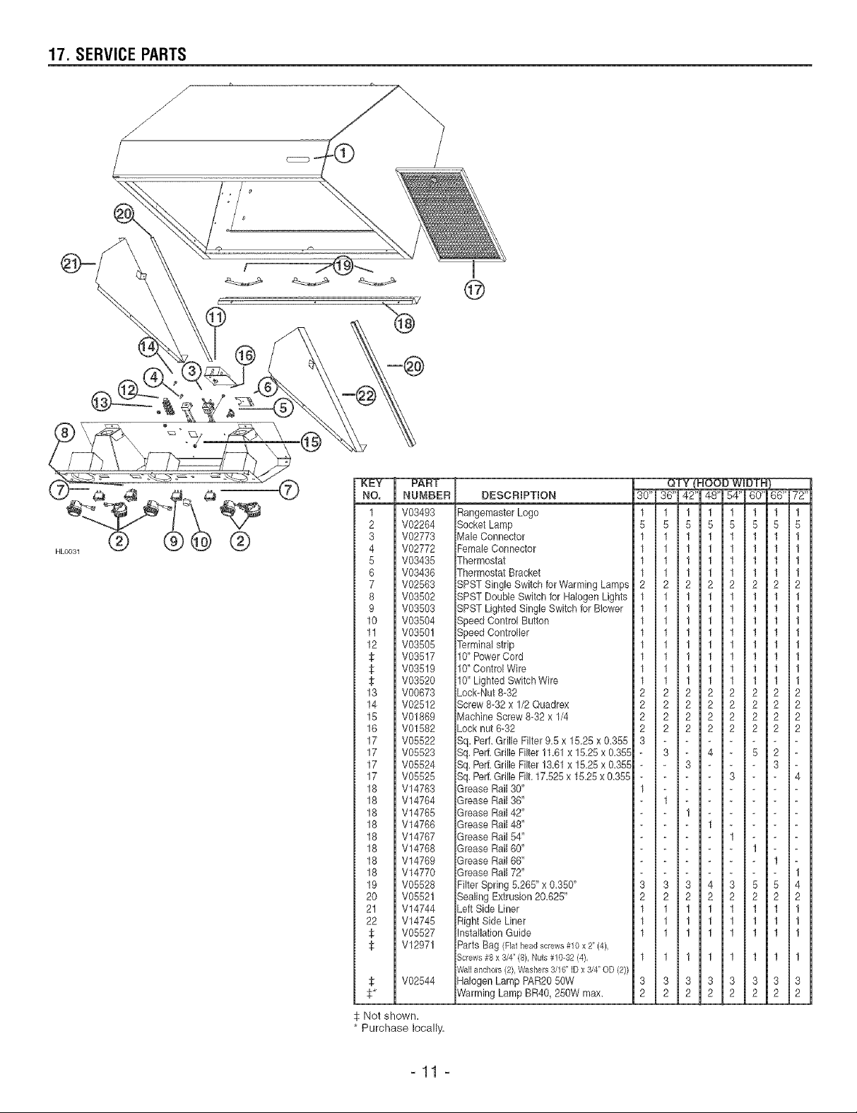
17. SERVICE PARTS
i
@
HLO031
NO.
NUMBER
1
V08493
2
V02284
3
V02773
4
V02772
5
V03435
6
V08436
7
V02583
8
V03502
9
V03503
10
V03504
11
V03501
12
V03505
V08517
V03519
V03520
13
V00673
14
V02612
15
V01889
16
V01582
17
V05522
17
V05523
17
V05524
17
V05525
18
V14763
18
V14764
18
V14765
18
V14768
18
V14767
18
V14768
18
V14769
18
V14770
19
V05528
2O
V05521
21
V14744
22
V14745
V05527
V12971
V02544
: Not shown.
Purchase locally'.
DESCRIPTION
RangemasterLogo
SocketLamp
Male Connector
FemaleConnector
Thermostat
Thermostat Bracket
SPST Single Switch forWarming Lamps
SPST DoubleSwitch for HalogenLights
SPST LightedSingle Switchfor Blower
Speed Control Button
Speed Controller
Terminalstrip
10" PowerCord
10"ControlWire
10" LightedSwitch Wire
Lock-Nut8-32
Screw 8-32x 1/2Quadrex
Machine Screw8-32 x 1/4
Locknut 6-32
Sq. Perf.Grille Filter 9.5 x 1&28 x 0.355
Sq.Pert Grille Filter11.61x 15.25x 0.355
Sq.Perf.GrilleFilter !&61 x !525 x 0.355
Sq.Perf.Grille Filt.17.525x 15.25x &355
GreaseRail 30"
GreaseRail 36"
GreaseRail 42"
GreaseRail 48"
GreaseRail 54"
GreaseRail 60"
GreaseRail 66"
GreaseRail 72"
FilterSpring 5265" x 0.350"
Sealing Extrusion2&625"
LeftSide Liner
Right Side Liner
InstallationGuide
Parts Bag (Flat head screws #10 x 2" (4),
Screws #8 x 3/4" (8), Nuts # 10-32 (4),
Wall anchors (2), Washers 3/16" ID x 3/4" OD (2))
HalogenLamp RAR2050W
WarmingLamp BR40, 250W max.
30" 36'
1 1
5 5
1 1
1 1
1 1
1 1
2 2
1 1
1 1
1
1
1
1
1
1
2
2
2
2
3
1
3
2
1
1
1
1 1
3 3
2 2
1
1
1
1
1
1
2
2
2
2
3
1
3
2
1
1
1
42' 48"
1 1
5 5
1 1
1 1
1 1
1 1
2 2
1 1
1 1
1 1
1 1
1 1
1 1
1 1
1 1
2 2
2 2
2 2
2 2
- 4
3 -
1 -
- 1
3 4
2 2
1 1
1 1
1 1
1 1
3 3
2 2
54" BO" BB" 72"
1 1 1 1
5 5 5 5
1 1 1 1
1 1 1 1
1 1 1 1
1 1 1 1
2 2 2 2
1 1 1 1
1 1 1 1
1 1 1 1
1 1 1 1
1 1 1 1
1 1 1 1
1 1 1 1
1 1 1 1
2 2 2 2
2 2 2 2
2 2 2 2
2 2 2 2
- 5 2 -
3 - - 4
3 5 5 4
2 2 2 2
1 1 1 1
1 1 1 1
1 1 1 1
1 1 1 1
3 3 3 3
2 2 2 2
Page 12

18. WARRANTY
BROANoNUTONE ONE YEAR LBMBTEDWARRANTY
Broan-NuTone warrants to the original consumer purchaser of its products that such products will be free from defects in materials or
workmanship for a period of one year from the date of original purchase. THERE ARE NO OTHER WARRANTES, EXPRESS OR
IMPLED, INCLUDING, BUT NOT LIMITED TO, IMPLED WARRANTES OR MERCHANTABILITY OR FITNESS FOR A PARTICULAR
PURPOSE.
During this one-year period, Broan-NuTone will, at its option, repair or replace, without charge, any product or part which is found to be
defective under normal use and service.
This warranty does not cover (a) normal maintenance and service or (b) any products or parts which have been subject to misuse,
negligence, accident, improper maintenance or repair (other than by Broan-NuTone), faulty installation or installation contrary to
recommended installation instructions.
The duration of any implied warranty is limited to the one-year period as specified for the express warranty. Some states and/or provinces
do not allow limitation on how long an implied warranty lasts, so the above limitation may not apply to you.
BROAN-NUTONE'S OBLIGATION TO REPAIR OR REPLACE, AT BROAN-NUTONE'S OPTION, SHALL BE THE PURCHASER'S SOLE AND
EXCLUSIVE REMEDY UNDER THIS WARRANTY. BROAN-NUTONE SHALL NOT BE LIABLE FOR INCIDENTAL, CONSEQUENTIAL
OR SPECIAL DAMAGES ARISING OUT OF OR IN CONNECTION WITH PRODUCT USE OR PERFORMANCE. Some states and/or
provinces do not allow the exclusion or limitation of incidental or consequential damages, so the above limitation or exclusion may not
apply to you.
This warranty gives you specific legal rights, and you may also have other rights, which vary from state to state, or province to another.
This warranty supersedes all prior warranties.
To qualify for warranty service, you must (a) notify Broan-NuTone at the address or telephone number below, (b) give the model number
and part identification and (c) describe the nature of any defect in the product or part. At the time of requesting warranty service, you
must present evidence of the original purchase date.
In case of discrepancies between the english version and the french and or spanish version of this warranty, the english version will prevail.
Broan-NuTone LLC, 926 West State Street, Hartford, WI 53027
(1-800-637-1453)
NuTone, _nc., 4820 Red bank Road, Cincinnati, OH 45227
(1-800-543-8687)
BroamNuTone Canada, 8nc., 1140 Tristar Drive, Mississauga, ON L5T 1H9
(1-888-882-7626)
_12 _
Page 13

RANGE AoST oR
GUIDE D'INSTALLATION
ET D'UTILISATION
DES HOTTES DE CUISINII_RE
SI_RIE RM60000
HBO026
/_kCONQUES POUR LA CUISSON DOMESTIQUE SEULEMENTZ_,
ilI;=_I=i=IIIE*{ ]_'_l=l;,_'J=l;,i*]=l[_'iIl_'_"]III;,t [*,]IIIE ]_'_,
INSTALLATEUR "LAISSER CE GUIDE AU PROPRI#TAIRE.
PROPRI#TAIRE "INSTRUCTION D'UTILISATION ET D'ENTRETIEN EN PAGE 22.
Broan-NuTone LLC, 926 West State Street, Hartford, WI 53027 (1-800-637-!453)
NuTone, Inc., 4820 Red Bank Road, Cincinnati, OH 45227 (1-800-543-8687)
Broan-NuTone Canada, Inc., 1140 Tristar Drive, Mississauga, ON L5T 1H9 (!-888-882-7626)
o_ • _ | o_
V05527 rev. D
Page 14

/%, AVERTISSEMENT
AVERTISSEMENT
AFIN DE REDUIRE LES RISQUES D'INCENDIE,
D'I_LECTROCUTION OU DE BLESSURES CORPORELLES,
SUIVEZ LES INSTRUCTIONS SUIVANTES :
N'utilisez cet apparel! que de la fa£on prevue par le
manufacturier. Si vous avez des questions, contactez
le manufacturier a I'adresse et au numero de tel6phone
indiques sur la garantie.
2.
Avant de reparer ou de nettoyer I'appareil, couper
I'alimentation 6Jectrique en verrouillant le panneau de
service afin d'eviter sa remise en marche accidentelle.
Si le panneau de service ne peut 6tre verrouille, y fixer un
avertissement en evidence.
3,
Les travaux d'installation et de raccordement electrique
doivent 6tre effectues par une personne qualifiee, conformement
aux codes et standards de construction, incluant ceux concernant
le feu.
4,
Une quantite d'air adequate est requise afin d'assurer une
bonne combustion et I'evacuation des gaz par la cheminee
darts le cas des equipements alimentes au gaz, afin de
prevenir les retours de cheminee. Conformez-vous aux
instructions et aux standards de securit6 des manufacturiers
d'equipement de chauffage, tels que publies par le National
Fire Protection Association (NFPA) et I'American Society for
Heating, Refrigeration and Air Conditioning Engineers
(ASHRAE), ainsi que les responsables des codes Iocaux.
Lorsque vous coupez ou perforez un mur ou un plafond,
prenez garde de ne pas endommager les ills electriques ou
tout appareil caches.
6,
Les ventilateurs avec conduits doivent toujours ¢tre ventiles
& I'exterieur.
7,
Ne pas utiliser cet appareil avec une commande de vitesse
semi-conducteur additionnelle.
8,
Afin de reduire les risques d'incendie, n'utilisez que des
conduits de metal.
9, Cet appareil dolt ¢tre mis a la terre.
AFIN DE RF:DUIRE LES RISQUES DE FEU DE CUISINIERE :
a) Ne jamais laisser les appareils de cuisson sans surveillance
Iorsqu'ils sent r6gles & feu vif. Les debordements engendrent de
la fumee et des deversements graisseux pouvant s'enflammer.
Chauffez I'huile lentement, & feu doux ou moyen.
b) Toujours mettre la hotte en marche Iorsque vous cuisinez a feu
vif ou que vous cuisinez des mets flambes.
c) Nettoyez regulierement la (les) roue(s) du ventilateur. Ne
laissez pas la graisse s'accumuler sur le ventilateur ou les filtres.
d) Utilisez le bon format de casserole. Servez-vous toujours de
casseroles et d'ustensiles appropries a la dimension de la
surface chauffante.
AFIN D'EVITER TOUT RISQUE DE BLESSURES DANS LE GAS
D'UN FEU DE CUlSINIERE, SUIVEZ CES INSTRUCTIONS* :
1. Etouffez les flammes avec un couvercle hermetique, une
tSle a biscuits ou un plateau metallique et ensuite, eteindre
le brt31eur. PRENEZ SOIN D'EVITER LES BROLURES. SI
LES FLAMMES NE S'ETEIGNENT PAS
IMMEDIATEMENT, EVACUEZ LES LIEUX ET APPELEZ
LES POMPIERS.
2. NE PRENEZ JAMAIS UNE CASSEROLE EN FLAMMES
DANS VOS MAINS - Vous pourriez subir des brQlures.
3. N'UTILISEZ PAS D'EAU, incluant linge a vaisselle ou serviette
mouilles - ceci pourrait occasionner une violente explosion.
4. N'utilisez un extincteur QUE DANS LE CAS O0 :
A. Vous savez qu'il s'agit d'un extincteur de classe ABC
et que vous en connaissez le fonctionnement.
B. l_incendie est petit et limite a I'endroit oQ il a debut6.
C. Les pompiers ont et6 avises.
D. Vous pouvez combattre I'incendie en ayant acces &
une sortie de secours.
* Tirees du "Kitchen Fire Safety Tips" publie par la NFPA.
ATTENTION
Pour usage domestique seulement. Ne pas utiliser pour
evacuer des vapeurs ou des produits dangereux
ou explosifs.
Afin d'eviter tout dommage au moteur et de debalancer
ou de rendre bruyante la roue du moteur, garder votre
appareil a I'abri des poussieres de placopl_tre et de
construction/renovation, etc.
Le moteur de votre hotte possede une protection
thermique qui eteindra automatiquement le moteur s'il
devient surchauffe. Le moteur repartira automatiquement
une lois refroidi. Si le moteur continue & arr6ter et &
repartir, faites-le verifier.
Pour une meilleure evacuation des odeurs de cuisine, le
bas de votre hotte devrait 6tre & un minimum de 24" et un
maximum de 30" au-dessus de la surface de cuisson.
Afin de reduire les risques d'incendie, assurez-vous
d'evacuer Fair & I'exterieur - Ne pas evacuer Fair dans
des espaces restreints comme I'interieur des murs ou
plafond ou dans le grenier, faux plafond ou garage.
Ce produit est 6quipe d'un thermostat pouvant faire
demarrer le ventilateur automatiquement. Afin de reduire
le risque de blessure, couper le courant & partir du
panneau electrique et verrouillez ou apposez un avertissement
sur le panneau afin de prevenir que la hotte soit mise en
marche automatiquement.
Afin de reduire les risques d'incendie et d'electrocution,
la hotte de cuisiniere Rangemaster Serie RM60000 dolt
6tre installee uniquement avec un des ventilateurs suivants :
RM325H, RM326H, 331H, 332H, 335 ou 336 (vendus
separement). Aucun autre ventilateur ne dolt 6tre utilise.
8,
Cette hotte ne dolt 6tre utilisee seulement qu'avec un
ensemble de cordon d'alimentation approuve.
9.
Veuillez consulter I'autocollant appose & I'interieur de la
hotte pour plus d'informations ou autres exigences.
-14-
Page 15

1,0
2,0
3,0
4,0
5,0
6,0
7,0
8,0
9,0
10,0
11,0
12,0
13,0
14,0
15,0
16,0
17,0
18,0
CHOISIR L:OPTION VENTILATEUR ET iNSTALLER LES CONDUITS ............................ 17
MESURER L:INSTALLATION ........................................................... 17
PRO:PARER EINSTALLATION ........................................................... 18
iNSTALLER LE DOSSERET ........................................................... 18
iNSTALLER LA LISIERE DE BOIS ....................................................... 18
iNSTALLER LA HOTTE ............................................................... 18
iNSTALLER LA TRANSiTiON ,_ LA PLAQUE VENTHLATEUR ................................... 19
iNSTALLER LA PLAQUE VENTHLATEUR SUR LA HOTTE ..................................... 19
BRANCHEMENT €:LECTRHQUE ......................................................... 19
SCHC:MA €:LECTRIQUE .............................................................. 20
iNSTALLER LE COUVREoCONDUHTS .................................................... 20
iNSTALLER LE VENTHLATEUR ......................................................... 20
iNSTALLER LES AMPOULES ET LES LAMPES CHAUFFANTES ............................... 20
iNSTALLER LES FHLTRES ............................................................. 21
ENTRETIEN ....................................................................... 22
FONCTIONNEMENT ................................................................. 22
PIECES DE REMPLACEMENT ......................................................... 23
GARANTIE ........................................................................ 24
_15 _
Page 16

Capuchons de
mur ou toit.
Ventilateurs
ext6fieurs
L_
Coudes et
volet
int6rieur
Conduits
MODELE 331H M( 335 MODELE 437
(Ventilateur ext.) (Ventilateur ext.) (Capuchon de toit
(600 pcm) OU (1200 pcm) OU & haut rendement)
332H (900 pcm) 336 (1500 pcm) !
t..................... _:::z:::zz::]_:::::::::::! ..................... ]
MOD#LE 418 MOD#LE 421
(Coude ajustabb 10" ronc (Vobt int6rieur vertical
\\ //
\\ z
• //
\
\ /
10" rond)
z
MODELE 441
(Capuchon de
toit 10" rond)
MODELE 647
(Capuchon de
mur 7" rend)
\ /
MODELE 415
(Coude ajustabb 7" rend)
MODELE 634 OU 644
(Capuchon de toit)
I
I
i
Choisir 1 des
5 transitions
PLAQUE VENT_LATEUR
MOD#LE 332KR
(& utiliser avec tousles
modebs de ventilateur exL :
//
/
\\
331 H, 332H, 335 et 336)
Choisir 1 des 3
syst#mes de ventilateur
(Conduit rend 10"- Sections de 2 pieds)
MODELE 410
/ I I I
/
/
/
J
MODELE 427 NIODELE 423 NODELE 424
(4'/2" x 18W' (4V2" x 18'/;' & 10" (4'/;' x 18V2" a
10" rond, 6" rond - verticab) 10" rond - horiz.
haut - lat6rale) avant / arri6re)
h................... J ....................... J....................... L ..................... J
\\
\
\
\
I I
MODELE 454 MOD#LE 453
(4W' x 18V;' a (4W'x 18V;' &
10" rond - 10" rond - honz
horiz, / droke) / gauche)
I I I
__VRE=CONDUITS
SE_R_ERMN
_ HOTTE _" (Ventiiateur int6rieur de 600 pcm
MODELE RM326H
VENTJLATEUR /
PLAQUE VENTILATEUR
(Ventilateur int6rieur de 1200 pcm
et pJaque ventiJateur)
(Conduit rond 7"- Sections de 2 pieds)
MODELE 407
i
i
MOD#LE RM325H
VENTILATEUR /
--- - _ _ _ PLAQUE VENT_LATEUR
SERIE
'_ & plaque ventilateur)R_60000
ventilateur et
(Avec contr61e
6clairage. Requis
pour toutes les
installations) FILTRES A CHICANES
OPT_ONNELS
SE_R_ERBF
B Y B R O A N - N U T O N E
SI RIE RM60000
SYSTI ME DE HOTTE
DE CUlSINII RE
=16=
DOSSERET S¢:R_E R_P
(Recouvrement de mur en acier inoxydabb
avec support assiettes. Facultatif)
HLO030
Page 17

1. CHOISIR L'OPTION VENTILATEUR
ET INSTALLERLES CONDUITS
2. MESURER L'INSTALLATION
La hotte de cuisini@e S@ie RM60000 fonctionne autant avec
un ventiIateur exterieur qu'int@ieur, Ella dolt _tre instalI_e
uniquement avec un des ventilateurs suivants : RM325H,
RM326H, 331H, 332H, 335 ou 336 (vendus s6par6ment),
Aucun autre ventilateur ne dolt 6tre utiJis&
NOTES : 1, Le ventiIateur exter[eur 331H, 332H, 335 ou 336
DOlT _tre [nsta!le avec Ia ptaque ventilateur modele
332KR (vendue separ6ment),
2, En pIus des modeles de ventiIateurs 6num@6s
cFdessus, cette hotte est aussi compatible avec
les anciennes versions de modeles de ventiiateurs
internes, soit Ies 325H et 326H, Si ces ventiIateurs
sent utiIises, jeter les instructions d'instalIation
comprises avec ces ventiJateurs, VeuiIIer contacter
notre soutien technique afin d'obtenir les nouvelIes
instructions d'installation,
Determiner&queIendroit etde quelle fagonlesconduits seront Iocalis6s,
Installer des conduits de dimension appropri_e, transition(s),
coude(s) et capuchon de toit ou de tour, au moteur utilis&
Les dimensions pour Jes JnstaIlations Jes plus courantes sent
indiqu_es plus bas,
Ajustez vos mesures pour Ies diff@entes hauteurs de plafond,
soffite, armoires ou surfaces de cuisson, Afin d"assurer un
meilleur fonctionnement, mahotte doit _tre aun minimum de
24" ({}10 ram) eta un maximum de 30" (762 ram) au=dessus
de masurface de cu[sson.
Plafoad
Armoire
standard
18"(457mrs)
au°dessus
de la surface
l J standard
I8"
(457 rara}
19"
(483 ram)
24" Distance minimate entre la
(610 rnm) hotte et Ussurface de cuisson
8 pL (2,44 ra)
Deasus de Ja
lisi_re de bois
Dosseret
S_.rie RMP
(facuUtatif)
MODELE RM325H A 1 VENTILATEUR
CONDUITS STANDARDS
MODELE RM326H ,&,2 VENTILATEURS
CONDUITS STANDARDS
VENTI/ATEUR EXTERIEUR
CAPUOHON DE TOIT
\
254 _fm)
(voir page 16)
l Surface de
-- standard
Surface de caisson hauteur
suisaon
36" (914 ram)
INSTALLATIONSOUS DES-ARMOIRES
STANDARDDE 18" HAUT
Plafond
Soffite standard _ t standard
12" 305 t#r_ ou 12' | 8' (2,44 ra)
Serie RMN (305 rara)E
CSernJ.eesoffite[j | 13"
€(33orara)
la liai_re
de boia
Dosaeret
S_rie RMP
(facultatif)
30" Distance ma×iraaUe
(762 ram) entre Is hotte et Ua
surface de cuisson
HN0028F
=17 =
J Surface de
" _ caisson staadard
Surface de caisson hauteur
36" (914 ram)
HH0027F
INSTALLATION AVEC UN SOFFITE DE 12" OU
LE COUVRE-CONDUITS OPT. SE_RiE RMN
Page 18

3. PRI_PARERL'INSTALLATION
Retirer Ia trousse d'instalIation de I'interieur de la hotte.
S'assurer que les items suivants soient presents :
-Lisiere de bois
-Guide d'installation
-Accessoires incluant :
.Les filtres (la quantite varie selon la largeur de la hotte)
.Sac de quincailIerie incJuant :
Vis #10 - 2" & t_te plate (4), Vis #8 - 3/4" (8), E_crous#10 - 32 (4)
Ancrages de gypse (2), Rondelles 3/16" DI X 3/4" DE (2)
A I'aide d'un tournevis Phillips #2 ou d'un Robertson #2, retirer les
vis retenant Ia hotte au fond de Ia caisse. Voir Jafigure ci-contre pour
Iocaliser les 4 vis. Jeter ces vis et retirer la hotte de la caisse.
HR0002
4. INSTALLERLE DOSSERET
(Facultatif) Serie RMP
Le dosseret dolt _tre instalIe avant Ia hotte puisque ce!Ie-ci couvre Ies vis d'installation du dossereL Afin de pouvoir installer Ie dosseret,
s'assurer d'avoir au moins 18" (457 ram) entre Ie dessus de la hotte et le panneau de contr61e de la cuisini@e ou de la surface de
cuisson (Voir les instructions fournies avec le dosseret.)
5. INSTALLERLA LISII:RE DE B01S
Mesurer puis tracer une ligne drolte, au-dessus de la surface de cuisson,
pour Ia Iocalisation de la Iisi@e ce bois. ,&,I'alde des vis a tSte plate
#10 - 2", fixer Ia Iisi@e de bois au tour en vous assurant d'atteindre les
montants. (Voir I'illustration de l'6tape 2 et celle c[-contre.)
6. INSTALLERLA HOTTE
En appuyant la hotte au rnur, ins@er la lisiere de bois dans la cavit6
arrJ_re de Jahotte.
HDOO68F
1. Mur
2. Lisigre de bois
3 Visa t#te fraisee
13" (330 ram) ou
19" (483 ram) du
plafond (volr page 17)
1-1/2"
(38 ram)
4. Locatisation des ancrages de gypse
5 Trace de I'arrigre de/a hotte
6 Montants
Fixer la hotte & la Iisi@e de bois & I'aide de (4) vis #8 - 3/4" (pour les
hottes de 30" et 36") ou (6) vis (pour les hottes de 42" et plus) fournies,
aux endroits indiques. En se servant des trous existants dans la hotte,
percer lemur de (2) trous de 3/16" pour Ies ancrages de gypse, aux
endroits indiqu6s. Puis, ins@er Ies deux ancrages de gypse et fixer Ia
hotte & ces ancrages avec les (2) vis restantes #8 - 3/4" et les (2)
rondelles fournies.
_18 _
Page 19

7. INSTALLERLA TRANSITION A LA PLAQUE VENTILATEUR
Meddles 423, 424, 427, 453 eu 454
Fixer la transition (s[ requise) & Ja plaque vent[lateur.
Sceller tous Ies joints avec du ruban a conduits.
NOTE : La plaque ventilateur du modele RM325N a un ventilateur se
branche directement a un conduit rend de 7", sans transition.
Les ventilateurs exter[eurs utilisent Ia plaque ventilateur 332KR;
elle se branche dlrectement b.un conduit rend de 10",sans transition.
8. INSTALLERLA PLAQUEVENTILATEUR SUR LA HOTTE
Amener Ie c&ble d'aJimentation a la Iocal[sation de la hotte. Pour les
d6ta[Is concernant I'installation de Ia plaque ventilateur, voir les
instructions comprises avec celle-ci (vendue s@arement). Installer Ia
plaque de facon & ce que son boi'tier 6lectrique soit a dro[te, Iorsque
vous fa[tes face a Ia hotte.
Si vous choisissez !'evacuation par I'arriere, retirer la plaque de I'arriere
de Ia hotte et !'installer sur le dessus pour couvr[r I'ouverture. Fixer b.
la hotte avec les m_mes 6crous denteles.
Pour une evacuation par Ie dessus, Iaisser Ia plaque a I'arri@e de la hotte.
Relier les conduits a la transition ou a la plaque ventilateur. Util[ser du
ruban a conduit afin d'assurer I'etanch6ite de tousles joints.
HDO063
1.E-crous denteles
2. Plaque sur le dessus de la hotte
3. Plaque ventilateur 8 I'arriere de la hotte
4. Couvemle du boPtier electrique
9. BRANCHEIVIENTItLECTRIQUE
Risque de chocs emectriques. Le raccordement eBectrique doit _tre effectue par du personnem quaHfie conformement au× codes 1
jet standards. Avant d effectuer le branchement coupez JaJimentation emectrique au panneau de service et verrouiHezde pour
[ev ter une mse en rnarche ace dente eo j
Ret[rer le couvercie du bo_tier electrique de Ia plaque ventHateur et mettre de c6te.
Retirer Fouverture pr6-amorc6e du bo_tier eIectdque. En instaIIant Ia pIaque Ventilateur, ins6rer une Iongueur de 6" de cb.ble
d'aHmentation darts le bo_t[er _lectr[que par son ouverture et brancher Ie c&ble en utiIisant le connecteur appropr[e.
Connecter le fiI NOIR au NOIR, Ie BLANC au BLANC et JefHVERT ou d_nud6 a Jav[s VERTE de m[se b.Jaterre.
ReinstaJJer Jecouvercle du boi'tier 61ectrique.
_19 _
Page 20

10. SCHI_IVIAI_LECTRIQUE
INTER. LAMPE CHAUF. DROITE
DOUILLE LAMPE CHAUF. DROITE
IN'[ER. VEN]',LA]'EUR N -_ B
5-15P
BORNIER
HEO018
11. INSTALLER LE COUVRE-CONDUITS OPTIONNEL
(OPTtONEL) S#de RMN
Voir les instructions incluses avec le couvre*conduits optionneL
12. INSTALLER LEVENTILATEUR
3 B--
" N__t¢
N D'ECLA, AGE
N DOUILLE AMPOULE GAUCHE
I CHAOF.GAUCHE _
DOUILLE AMPOULE DROITE
DOUILLE AMPOULE CENTRALE
DOUILLE LAMPE CHAUF, GAUCHE
Pour installer le ventilateur, voir les instructions fournies avec celui-cL
Une lois install6, brancher le ventilateur et Ie cordon de Ia bo_te
electrique aux prises, a I'interieur de la hotte. NE PAS brancher
ensemble les deux cordons.
HEO003
13. INSTALLER LESAIVIPOULESETLAIVIPESCHAUFFANTES
InstaIIer deux lampes chauffantes. Utiliser des infrarouges de format BR40, 250W maximum (non incluses).
Installer trois ampoules halogenes. Utiliser des ampoules de format PAR 20, 50W (non incluses).
20
Page 21

14. INSTALLER LES FILTRES
HJest recommande d'instalIer d'abord Ies flltres s[tues aux extr_m[t6s et de term[ner par Je(s) fiJtre(s) du centre.
1. Ins@er Ia pattie sup@ieure du filtre dans la hotte (c6te de la poign6e).
2. Falre p[voter Ia pattie inferieure vers I'[nt@ieur de la hotte.
3. Placer Ie f[Itre sous I'attache s[tuee au fond de Ia hotte.
4. En util[sant la poignee, gl[sser Jef[Itre sous Ja )i_ce de retenue int@ieure.
\\\\\
\
\\\\\
\\
\ HD0065
HD0024
Des filtres de remplacement sent disponlbles chez votre detaillant. Consulter J'etiquette s[tuee & J'[nt@ieur de Jahotte pour Je num@o
de pJ6ce et le format.
Filtres # chfcane
Ces filtres sent dispon[bles en option. Pour Ies commander, se ref@er au tableau ci-dessous pour trouver Je num@o de kit correspondant
& Jahotte. Pour Jes installer, se ref6rer & JafeuilJe d'instruct[on incluse darts Je kit de filtres b.chicane).
KIT # LARGEURDE HOTTE
RBF6030 30"
RBF6036 36"
RBF6042 42"
RBF6048 48"
RBF6054 54"
RBF6060 60"
RBF6066 66"
HDO011
FtLTRE A CHICANE (TYPtQUE)
RBF6072 72"
_21
Page 22

15. ENTRETIEN
16. FONCTIONNEMENT
Filtres
Les filtres doivent 6tre nettoy6s fr6quemment. Utiliser une solution
d'eau chaude et de d_tergent. Les fiItres sont Iavables au
lave-vaisselle. Les filtres doivent _tre laves plus souvent sJ vos
habitudes de cuisson g6n@ent pJus de graisse - comme par
exemple de la friture ou des aliments sautes au wok.
Pour retirer les filtres, pousser chaque filtre vers Ie bas en utiJisant
la poign6e afin des d6gager de Ia piece de retenue. PuJs,
pousser vers I'int6rieur de Ia hotte et les retirer.
Nettoyage du ventilateur
RetJrer Ies fiItres pour acceder au ventilateur. Passer I'aspirateur
pour Ie nettoyer ; ne pas I'immerger dans I'eau. Pour pJus de
d6tails, consuJter Je guide d'Jnstruction du ventilateur.
Goutde_e
La goutti@e dolt 6tre nettoyee fr6quemment, sutout sJdes filtres
&chicanes sont uti!is_s. Retirer Ies filtres, puis desassembler Ia
gouttiere de Ia hotte en d6vissant ses 3 vis de retenue. Voir
I'illustration ci-dessous.
Consulter la section nettoyage de I'acier inoxydable dans la section
nettoyage de la hotte ci-dessous. Une lois Ia goutti_re propre et
seche, la r_assembler sur la hotte et r6installer les filtres.
Nettoyage de la hotte
Acier inox_dabte : Comment preserver son
,_APPARENCE CTINCELANTE 7,
A faire :
- Laver r6guli@ement les surfaces _ I'aided'un chiffon ou linge propre
imbib6 d'eau tilde et de savon doux ou d_tergent _ vaisselle.
- Toujours nettoyer dans Ia direction des lignes de grains (direction
du polissage).
- Toujours bien rincer avec de I'eau propre (2 ou 3 lois) et
essuyer compl_tement.
- Vous pouvez 6galement utiliser un nettoyant domestique
congu sp6cialement pour J'acier inoxydable.
_, ne pas faire :
- N'utilisez aucune Iaine d'acier ou d'acier inoxydable ou tout
autre grattoir pour enlever Jasalete tenace.
- N'utilisez aucune poudre nettoyante abrasive ou rugueuse.
- Ne laissez pas Ia salete s'accumuler.
- Ne pas laJsser Ia poussiere de platte ou tout autre r6sidu de
construction/r6novation atteindre Ia hotte. Couvrir Ia hotte pour
la dur_e des travaux pour s'assurer qu'aucune poussi_re ne
colic &tla surface de I'acier.
_, _,viter moredu choix d'un detergent :
- Tous produits nettoyants qui contiennent des agents de
blanchiment ;ils attaqueront I'acier inoxydable.
- Teus produits contenant du chlorure, fluorure, lode ou
bromure ;ils det6rioreront rapidement Ies surfaces.
- Tous produita cornbuetiMes utilJs6s pour le nettoyage :acetone,
alcooL ether, benzol etc. :iIs sont hautement expIosifs et ne
devraient iamais 6tre utilis6s pros d'une cuisini@e.
Surfaces peintes :
Nettoyer avec de I'eau chaude additionnee seulement d'un
d6tergent doux. S'il y a d6coIoration, utiIisez une bonne cire
peinture telIe qu'une cire d'automobiJe. (NE PAS UTlUSER de
nettoyant abrasif ou de nettoyant a porcelaine.)
Touiours mettre en marche la hotte avant de commencer Ia
cuisson afin d'etablir une circulation d'air dans Ia cuisine. Aussi,
laisser la hotte fonctionner quelques minutes apr@s I'arr@t de Ia
cuisini6re afin de nettoyer Fair. Ceci aidera _ garder la cuisine
plus propre et plus claire.
HO0004
1.Lampes r_chauds 4. Interrupteurs de la mpes halog_nes
2. Interrupteurs de lampes rAchauds 5. Interrupteur Marche/Arr_t du ventilateur
3. Lampes halog_nes 6. ContrSle de la vitesse du venfilateur
Lampes rechauds
Chaque lampe rechaud (item 1de I'illustration ci-dessus) poss_de
son propre interrupteur Marche/Arr@t(item 2 de I'illustrationci-dessus).
N'utiliser que des ampoules infrarouges BRA0, 250W max.
(non incluses).
Eclairage (Halogene)
Les interrupteurs doubles Marche/Arr_t (item 4 de I'iIIustration
ci-dessus) contr6ient Ies lampes halog@nes (item 3 de I'illustration
ci-dessus).
LJinterrupteur avant contr61e Ia lampe centrale. LJinterrupteur
arri6re contr61e Ies deux lampes de c6te. Choisir une, deux ou
trois Iampes selon vos pref6rences d'6cIairage.
Utiliser des ampoules haIogenes PAR 20, 50W (non incluses).
Vendlateur
Le ventilateur est contr61e par (2) commandes.
Utiliser I'interrupteur Iumineux rouge (Marche/Arr6t) (item 5 de
I'illustration ci-dessus) pour actJonner ou arr@er le moteur. Une
lois mis en marche, le ventiIateur fonctionnera & la vitesse pre-
selectionn6e par Ia commande de vitesse (item 6 de I'iIIustration
ci-dessus).
Pour augmenter la vitesse du ventilateur, toumer le bouton de
contr61e de Ia vitesse dans le sens horaire -dans le sens
anti-horaire pour ralentir la vitesse.
HEAT SENTRY _
Votre hotte est munie d'un thermostat HEAT SENTRY Mc, Ce
thermostat est un dispositif qui actionnera ou augmentera la
vitesse du ventiIateur s'il d6tecte une chaleur excessive
au-dessus de Ia surface de cuJsson.
1) S[ Ie ventilateur n'est pas en marche - il actionnera le
ventiIateur en haute vitesse.
2) S[ Ie ventilateur fonctionne en basse vitesse - le ventilateur
tournera en haute vitesse.
Lorsque Ia temperature revient & la normale, le ventilateur
retourne & sa vitesse d'origine.
- 22 -
Page 23

17. PIF:CESDE REMPLACEMENT
i
@
HLO031
NO.DE NO. _E LA
REE P ECE
1 V03493
2 V02264
3 V02773
4 V02772
5 V03435
6 V03436
7 V02563
8 V03502
9 V03503
10 V03504
11 V03501
12 V03505
$ V03517
$ V035!9
$ V03520
13 V00673
14 V025!2
15 V01869
16 V01582
17 V05522
17 V05523
17 V05524
17 V05525
18 V14763
18 V14764
18 V14765
18 V14766
18 V14767
18 V14768
18 V14769
18 V14770
19 V05528
20 V05521
2! V14744
22 V14745
$ V05527
$ V12971
$ V02544 Ampoule halogene RAR20 50W 3 3 3 3 3 3 3
$* Ampoule chauffante BR40, 250W max_ 2 2 2 2 2 2 2
_: Non illustr_
* S'approvisionner [ocalement
DESCRIPTION
LogoRangemaster 1 1 1 1 1 1 1
Douille 5 5 5 5 5 5 5
Connecteurm_le 1 1 1 1 1 1 1
Connecteurfemelle 1 1 1 1 1 1 1
Thermostat 1 1 1 1 1 1 1
Support pourthermostat 1 1 1 1 1 1 1
Inter.simple UPSTpourlampechauffante 2 2 2 2 2 2 2
Inter.doubleUPST pour lampe halogene 1 1 1 1 1 1 1
Inter.simple illumine UPSTventilateur 1 1 1 1 1 1 1
Boutoncontr61edevitesse
Contr61ede vitesse
Plaque_ bornes
Cordond'alimentation10"
Fil de contr61e!0"
Fil interrupteurillumine 10"
Ecrou dentele8°32
Visquadrex 8°32x 1/2
Vismecanique 8°32x 1/4
Ecrou dentele6°32
Filtre_ grillecarree 9,5 x 15,25 x 0,355 3
Filtre_ grillecarree 11.61x 15.25x 0.355 - 3 4 5 2
Filtre&grille carrie 13.61x !525 x 0,355 - 3 3
Filtregrillecarr6e 17_525x 1525 x 0,35[
Goutti@e30"
Geutti@e36"
Geutti@e42"
Goutti@e48"
Goutti_re54"
Geutti@e60"
Goutti@e66"
Goutti@e72"
Ressort de filtre 5.265" x 0.350"
Extrusiond'etancheite 20,625"
Paroiinterieure gauche
Paroiint@ieure @oRe
Guided'installation
Sacd'installation (VisL,t@e plate #10 x 2" (4),
Vis#8 x 3/4"(8), @rous #10-32(4),Ancragesde 1 1 1 1 1 1 1
gyp,se(2),Rondelles3/16"DI x3/4"DE(2))
1 1 1 1 1 1 1
1 1 1 1 1 1 1
1 1 1 1 1 1 1
1 1 1 1 1 1 1
1 1 1 1 1 1 1
1 1 1 1 1 1 1
2 2 2 2 2 2 2
2 2 2 2 2 2 2
2 2 2 2 2 2 2
2 2 2 2 2 2 2
3
1
1
1
1
1
3 3 3 4 3 5 5
2 2 2 2 2 2 2
1 1 1 1 1 1 1
1 1 1 1 1 1 1
1 1 1 1 1 1 1
1
1
23
Page 24

18. GARANTIE
GARANT+E LIM+TEE D'UN AN DE BROAN+NUTONE
Broan-NuTone garantit & I'acheteur consommateur initialde ses produits qu'ils sent exempts de tous d6fauts dans Ies matieres premieres
eu Ia main-d'_uvre pour une p6rlode d'un an _ compter de la date d'achat par le consommateur initial. IL N'Y A PAS D'AUTRES
GARANTIES, EXPRIMEES OU IMPLICITES, INCLUANT, MAIS NON LIMITE'._ESAUX GARANTIES IMPLICITES POUR FIN DE
COMMERCIALISATION ET DE CONVENANCE DANS UN BUT PARTICULIER.
Durant cette periode d'un an, Broan-NuTone, _ sa discretion, r6parera ou remplacera gratultement, tout prodult ou piece qui s'avere
defectueux et ayant 6t_ utilise nomalement et d'une maniere non abusive.
Cette garantle ne couvre pas (a) I'entretien et Ie service normal ou (b) tout prodult ou pl_ce endommage par suite de mauvals usage,
negligence, accident, entretJen lnapproprl_ ou reparation (autre que par Broan-NuTone), mauvaise lnstallatlon ou
installation non conforme au mode d'installation recommande.
La dur6e de toute garantie lmpllclte est limit6e _ une p6rlode d'un an tel que specifi6 pour la garantle exprimee.
L:ENGAGEMENT DE BROAN-NUTONE DE RE'PARER OU DE REMPLACER, AU CHOIX DE BROAN-NUTONE, SERA LA SEULE
OBLIGATION EXCLUSIVE SOUS CETTE GARANTIE. BROAN-NUTONE NE SE TIENDRA PAS RESPONSABLE DES DOMMAGES
DIRECTS, INDIRECTS OU SPE_CIAUX SURVENANT ,_ CAUSE DE OU EN RAPPORT ,A.EUTILISATION OU LA PERFORMANCE DE
SES PRODUITS.
Cette garantie vous donne des drolts legaux sp_cifiques et iI se peut que vous ayez d'autres drolts qui varient d'un _tat b. un autre, ou
d'une province a I'autre. Cette garantie annule toutes les autres garantles pr6c_dentes.
Pour Ie service sous garantie, vous devez (a) aviser Broan-NuTone a J'adresse ou au numero de t61ephone mentionne plus bas, (b) donner
le numero du modele et I'identificatlon de la piece et (c) d6crire Ia nature de tout defaut dans le produit ou Ia pi6ce. Au moment de Ja
demande de service sous garantie, vous devez presenter une preuve de la date d'achat initial du dlt prodult.
En cas de divergences entre Ia version anglalse de cette garantie et la version frangalse eb]ou espagnole, Javersion anglaise pr6vaudra.
Broan+NuTone LLC, 926 West State Street Hartford, WI 53027
(1-800-637-1453)
NuTone, Inc., 4820 Red Bank Road, Cincinnati, OH 45227
(1+800-543-8687)
Broan+NuTone Canada, Inc., 1140 Tdstar Drive, M[ss[ssauga, ON LST 1H9
(1-888-882-7626)
+24 +
Page 25

RANGE AoST oR
MANUAL DE INSTALACION
Y UTILIZACION DE LAS
CAMPANAS SERIE RM60000
HB0026
/_CONCEBIDO SOLO PARA USO DOMESTICO/_
INSTALADOR: DE JAR ESTE MANUAL AL PROPRIETARIO
PROPRIETARIO: INSTRUCClONES DE UTILIZAClON Y MANTENIMIENTO EN LA P/_,GINA 34
Broan-NuTone LLC, 926 West State Street, Hartford, WI 53027 (1-800-637-!453)
NuTone, Inc., 4820 Red Bank Road, Cincinnati, OH 45227 (1-800-543-8687)
Broan-NuTone Canada, Inc., 1140 Tristar Drive, Mississauga, ON L5T 1H9 (!-888-882-7626)
V05527 rev. D
Page 26

ADVERTENCIA ADVERTENCIA
PARA REDUCIR EL RIESGO DE INCENDIO, DESCARGA
ELECTRICA, O LESIONES A PERSONAS, CUMPLA LOS
SIGUIENTES PUNTOS :
1. Solamente use esta unidad de la manera propuesta por
el fabricante. Si tiene alguna pregunta, communiquese
con el fabricante en la direccion o telefono anotados en
la garantia.
2. Antes de limpiar o poner en servicio la unidad, apague
el interruptor en el panel de servicio, y asegure el panel de
servicio para evitar que se encienda accidentalmente.
Cuando el dispositivo para desconectar el servicio electrico
no puede ser cerrado con algOn tipo de traba, sujete
fuertemente al panel de servicio, una etiqueta de
advertencia prominente.
3. El trabajo de instalaci6n y el alambrado electrico deben
Ilevarse a cabo por personal calificado de acuerdo con
todos los codigos y las normas aplicables, incluyendo
los codigos y normas de construccion contra incendios.
4. Se requiere una cantidad de aire suficiente para la
combustion y escape de gases por la chimenea del
equipo de quemado de combustible para evitar salirse
de las especificaciones y estandares de seguridad del
fabricante, tales como los publicados por la Asociaci6n
nacional de proteccion contra incendios (NFPA pot sus
siglas en Ingles), y la Sociedad americana de ingenieros
de calefaccion, refrigeraci6n y aire acondicionado
(ASHRAE por sus siglas en Ingles), y los codigos de las
autoridades locales.
5. Cuando corte o taladre en una pared o techo, no daSe
los cables electricos, ni otras instalaciones ocultas.
6. Los ventiladores con conductos deben siempre ventilar
hacia el exterior.
7. No use esta unidad con ningQn otro control de velocidad
de estado s61ido.
8. Para reducir todo riesgo de incendio, use solamente
conductos en metal.
9. Esta unidad se debe conectar a tierra.
PARA REDUCIR EL RIESGO DE INCENDIO DE GRASA EN
LA SUPERFICIE DE LA ESTUFA:
a) No deje nunca los aparatos de cocer sin vigilancia a
fuego vivo. Los desbordamientos producen humo y
derrames grasiendos que pueden inflamarse. Caliente el
aceite despacio, a fuego lento o mediano.
b) Ponga en marcha siempre la campana al cocinar a
temperaturas elevadas o al cocinar alimentos flameados.
c) Limpie los ventiladores con frecuencia. No deje que la
grasa se acumule en el ventilador ni en el filtro.
d) Utilice cacerolas de tamaSo apropiado. Emplee siempre
un recipiente adecuado para el tamaSo de la placa.
- 26 -
PARA EVITAR RIESGO DE LESIONES PERSONALES EN
CASO DE INCENDIO DE GRASA EN LA SUPERFICIE DE LA
ESTUFA, OBSERVE LO SIGUIENTE :*:
1. Cubra y sofoque las llamas con una tapa ajustada,
azafate de hornear galletas, o azafate de metal, y luego
apague el calentador. TENGA CUIDADO PARA EVITAR
QUEMADURAS. Si la llamas no se apagan inmediatamente,
HAY QUE EVACUAR Y LLAMAR LOS BOMBEROS.
2. NUNCA ALCE UNA SART#:N QUE TENGA LLAMAS -
Usted se puede quemarse.
3. NO USE AGUA, incluyendo trapos, lavaplatos mojados o
toallas- puede que ocurran explosiones de vapor violentas.
4. Use un extintor SOLAMENTE si :
A. usted sabe que tiene un extintor ABC y sabe usarlo.
B. El incendio es pequeSo y esta restringido al &rea
donde empezo.
C. Se esta Ilamando los bomberos.
D. Usted puede tratar de apagar el fuego teniendo
una salida detr&s suyo.
* Basado en "Kitchen Fire Safety Tips" publicado por la
Asociaci6n National de protecci6n contra Incendios (NFPA).
PRECAUCION
1. Solo para uso de ventilacion general. No se use para
extraer materiales o vapores peligrosos o explosivos.
2. Para evitar daSos al cojinete del motor y/o impulsore ruidosos
o desequilibrados, mantenga la fuente de potencia lejos
de rocios de pared seca, de polvo de construccion, etc.
3. El motor de la campana tiene un dispositivo contra
sobrecargas termicas que apaga el motor en forma
autom&tica si este se sobrecalienta. El motor volver&
arrancar cuando se enfrie. Si el motor sigue apag&ndose,
haga verificar la campana.
4. Para Iograr una mejor captura de las impurezas
producidas al cocinar, la parte inferior de la campana
deber& estar a un minimo de 24 y un m&ximo de 30
sobre el nivel la superficie para cocinar.
5. A fin de reducir los riesgos de incendio y para bien evacuar el
aire de salida, asegQrese de evacuar el aire al exterior - No
evacue el aire en espacios limitados como el interior de
las paredes o del techo o en el desv&n, falso techo o garaje.
6. Este producto est& equipado de un termostato que
puede hacer partir el ventilador autom&ticamente. Para
evitar los riesgos de da5o, apague la corriente del panel
electrico y cierre con candado o afiche una advertencia
en el panel para prevenir que la campana funcione
autom&ticamente.
Para reducir el riesgo de incendio y descarga electrica,
esta campana Rangemaster RM60000 serie debe ser
instalada con ventilador modelo RM325H, RM326H,
331 H, 332H, 335 o 336 solamente. Otros ventiladores no
pueden reemplazar a este ventiladores. (Ventiladores
vendidos separadamente.)
8,
Utilice solo con un conjunto autorizado de conexion con
cordon.
9.
Lea la etiqueta de especificaciones en el producto para
mayor informacion y requisitos.
Page 27

1,0
2,0
3,0
4,0
5,0
6,0
7,0
8,0
9,0
10,0
11,0
12,0
13,0
14,0
15,0
16,0
17,0
18,0
SELECCIONE LA OPTION VENTILADOR Y INSTALE LOS CONDUCTOS ......................... 29
MIDA LA INSTALAClON ............................................................... 29
PREPARE LA INSTALACION ........................................................... 30
INSTALE LA PLACA PARA SALPICADURAS ............................................... 30
INSTALAClON DE LA TIRA DE MADERA ................................................. 30
INSTALE LA CAMPANA ............................................................... 30
INSTALE LA TRANSICION EN PLACA DEL VENTILADOR .................................... 31
INSTALE LA PLACA DEL VENTILADOR EN LA CAMPANA .................................... 31
CONECCION ELC:CTRICA ............................................................. 31
ESQUEMA ELC:CTRICO .............................................................. 32
INSTALE LA CHIMENEA DE iNTRADOS OPCIONAL ........................................ 32
INSTALE EL VENTILADOR ............................................................ 32
INSTALE LOS BOMBILLAS Y LAMPARAS TERMOGENA ..................................... 32
INSTALE LOS FILTROS ............................................................... 33
MANTENIMIENTO ................................................................... 34
FUNCIONAMENTO .................................................................. 34
REPUESTOS ....................................................................... 35
GARANTiA ........................................................................ 36
27
Page 28

Tapas del
muro o techo
Ventiladores
exterior
L_
Codes y
compuerta
de tire
Conductos
MODELO 331N MODELO 437 MODELO 441
(Ventilador ext.) (Ventilado ext.) (Tapa de techo de (Tapa de techo
(600 pcm) O (1200 pcm) O Mta capacidad) redondo 10")
332N (900 pcm) 336 (1500 pcm) !
t..................... _::rz::zz2%:::::::::::! ..................... ]
!
MODELO 418 MODELO 421
(Codo ajustado de 10" redondo) (Compuerta de tiro en
\\ //
\\ /
• //
\
\ /
I[nea vertical redondo 10")
z
MODELE 647
(Taps de muro
redondo 7')
MODELO 634 O 644
\ /
MODELO 415
(Codo ajustado de T' redondo)
I
I
i
(T3pa de techo)
Seleccione 1 de 5
transicidns
PLACA DEL VENTJLADOR
MODELO 332KR
(Utilizar con todos los modeios
de ventiladores ext : 331 H
332H, 335 et 336)
Seleccione 1 de 3
systemas de ventiladores
(Conducto redondo de 10" - Secciones de 2 pies)
MODELO 410
(Conducto redondo de 10" - Secciones de 2 pies)
MODELO 407
...................... T........ _.............. !....... q - ]
I I
NODELO 427 NODELO 423 MODELO 424 NODELO 454 NODELO 453
(4VP'x 18'/#' a (4W' x 18'/2" a (4'/P' x 18W' a 10" (4'/f' x 18W' a (4W' x 18'/P' a
10" redondo - 10" redondo - redondo - horiz. 10" redondo - 10" redondo -
6" altura -lateral) vertical) frente / atr_s) horiz. /der.) horiz. / izq.)
I I
h................... J ....................... J....................... h ..................... J
i i i !
__ENEAS DE
INTRADOS OPCiONAL
RMN SERIE
MODELO RM326N
VENTILATOR / PLACA
VENTILADOR
(1200 pcm ventiiador interior
y placa ventilador)
controies dei
(Pabeii6n con
ventiiador y
iluminaci6n.
Se requiere para FtLTROS DE ZiG ZAG
todas las instMaciones) SERiE RBF
- --- - _ _ _ VENTILADOR
MPANA ' interior y placa ventilador)
RIE R_,_60000 _
-_. (600 pcm ventiiador
_x
1
i
i
MODELO RM325N
VENTILADOR / PLACA
OPOEONAL
BY BROAN_NUTONE
SERIE RM60000
SYSTEMA DE CAMPANA
= 28 =
PLACA PARA SALPICADURAS
RMP SERIE
(Cubierta para pared, de acero inoxidable
con estantes para cMentamiento.
Opcional )
HLO030
Page 29

1. SELECCIONELA OPTIONVENTILADORY INSTALE
LOSCONDUCTOS
2. MIDA LA INSTALACION
La campana Serie RM60000 funciona tanto con un ventllador
exterior como interior. Esta campana debe ser instalada con
ventilador mode!o RM325H, RM326H, 331H, 332H, 335 o 336
solamente. Otros ventiladores no pueden reemplazar a este
ventiladores.
NOTAS: 1. El ventilador exterior 331H, 332H, 335 o 336 debe
ser instalado con la placa del ventilador modeto
332KR (vendida separadamente).
2. Adem_s de modelos de ventiladores Iista arriba, este
campana es tambJen compatible con antiguo modelos
de ventiladores intemos: 325H y 326H. Si este ventHadores
son utilizados, descartar las instrucciones de instataci6n
incluyes con este ventiladores. Oontactar con nuestro
soporte t6cnico por obtener Ias nuevas instrucciones
de instalaci6n.
Planifique d6nde y come se van a colocar los conductos.
Instale ductos, transiciones, codes y remate de pared o de
techo de tamale adecuado para el tipo de ventilador que este
usando.
REMATE DE TECHO
\
24' A 30" (609 A 762 mm)
SOBRE EL NiVEL DE LA
SUPERFICIE PARA COCINAF{
f
MODELORM325H CON 1 VENTILADOR
CONDUCTOSTIPJCOS
A continuaci6n se muestran las dimensiones para las
instalaciones m_s comunes.
A]uste sus medidas para Ias diversas alturas de techos,
intrad6s, gabinetes o superficies para cocinar. Para mograr un
funeionamiento adeeuado, Baparte inferior de _a eampana
debera eatar entre 6!0 y 762 mm (24 y 30 pumg,) sobre el
nivel de masuperficie para cocinar.
Teeho
Gabinete 8' (2,44 m)
estandar de
18" (457ram)
Jeaitura sobre 19"
la supetficie (483 ram)
pata cocinar
"_- _ Parte superior
Cam
est_ndar de
de Uatira de
madera de
montaje
C
7_- Placa para
24" (opcional)
(810 ram) Distar_Jamir_imaentreJacarnpana
INSTALACIONDEBAJO UNA ARMARIO
EST,_,NDARDE 18" DE ALTURA
.... salpicaduras
serie RMP
y la superficie para cocinar
SuperfJc_e
para cocinar
est_ndar de
-- 36" (914 ram)
de aitura
HHO028E
MODELO RM326HCON 2VENTtLADOR
CONDUCTOSTIPICOS
VEN1 kLADOR EXTERIOR
10"(254mm)
CODO
REDONDO
PLACA DEL
f
MODELO 331H, 332H, 335 O 336
VENTILADOR EXT. CONDUCTOS TIPICOS
10'(114×470 a
254 ram)
(vet p_glna 28)
Techo
est_ndar de
8' (2,44 m)
Pa_e superior
de Jatira de
madera de
montaje
....... sa_picaduras
30" Distancia m4xima entre la
(762 ram)
Superficie para cociRar 36" (914 ram)
Plata para
ser_e RMP
(optional)
campana y la superficie
para cocinar
Superficie
para cocinar
estandar de
de altura
HH0027E
INSTALACiONCON INTR_,DOS ESTANDARDE
12"O CHIMENEA DE INTRADOS SERE RMN
29
Page 30

3. PREPARELA INSTALACION
Quite e! estuche de instaIaci6n de dentro de la campana.
AsegQrese que Ios art[culos siguientes estAn incluidos:
-Tira de madera
-Manual de instaIaci6n
-Complementos incluyendo:
.Los filtros (la cantitad varia conforme a Ios dimensi6nes de la campana)
.Bolsa de piezas inctuyendo:
Tornillos #10 - 2" con pIana cabeza, (4), TornilIos #8 - 3/4" (8),
Tuercas #10 - 32 (4), Anclas de la pared (2), Arandelas 3/18" Di X 3/4" De (2)
Usando un destornillador Phillips #2 o un Robertson #2, destornille
la campana del fondo de Ia canasta. Refierase a la figurar para
Iocalizar Ios 4 tornillos. Tire los tornillos y quite la campana de la
paleta de madera.
HR0002
4. INSTALELA PLACAPARASALPICADURAS
(Opcionat) Serie RMP
La placa para saIpicaduras se debe instalar antes que Ia campana debido a que este cubre los tornilIos de montaje de la placa para
salpicaduras. Para instaiar la placa para saipicaduras, asegQrese de tenet 18" (487 mm) entre debajo de la campana y el panel de
control de la cocina o encima de la cocina (Vea las instrucciones incluidas con la placa para salpicaduras.)
5. INSTALACIONDE LATIRA DE IVIADERA
En la pared, mida y marque una I[nea de nivel para Ia tira de montaje
de madera pot encima de Ia posici6n de la superficie para cocinar (yea
las dimensiones en Ias ilustraciones del paso 2 y debajo). Usando los
tornilIos con plana cabeza #10 - 2", asegure la tira de montaje a Ia
pared de manera de alcanzar los traversafios de la pared. (Vea figura
aI lade.)
6. INSTALELA CAMPANA
Para instalar la campana en su lugar, use la tira de madera para
apoyar la cavidad de la parte de atrAs de la campana.
1-I/2" :
38 mm I I
"I _ I t-l/
HDOO68E
1. Pared
2. Tira de madera
3 Tomillosde cabeza avellanar 6 Traversados
4. Locallzacion de las anctas de la pared
5. Atras de/a campana
19" (483 ram) de
techo (yea p&gina 29)
!
1_1/2"
(38 ram)
Segure la campana a Ia tira de Ia montura con los 4 tornillos
#8 - 3/4"(para una campana de 30" o 38" larga) o 6 tornillos (para las
campanas de 42" y mas Iarga) incUdos en Iugar indicado. Perfora (2)
aguieros de 3/18" de largo en Ia pared para las anclas de pared en
lugar indicado. Entonces, instale las 2 anctas de la pared y asegure la
campana con los 2 Oltimos tornillos #8 - 3/4" y las 2 arandellas.
- 30 -
Page 31

7. INSTALELA TRANSIClON EN LA PLACADEL VENTILADOR
Modelos 423, 424, 427, 453, o 454
Monte la transicion en la placa del ventilador.
Use cinta para ductos para que todas las juntas sean seguras y
hermeticas.
NOTA: La placa de un solo ventilador del modelo RM325H se conecta
directamente al conducto redondo de 7", sin transicion.
Los ventiladores exterior usan el modelo de la placa del ventilador
332KR que se conecta directamente al conducto redondo de
10", sin transicion.
8. INSTALE LA PLACA DEL VENTILADOR EN LA CAMPANA
Tienda el cable de energia al sitio de la instalacion. Por detalles referente
a la instalacion de la placa del ventilador, vea las instrucci6nes incluida
con esa (vendida separadamente). Instale la placa de tal forma que la
caja de cableado este fuera a la derecha, cuando ustedes hace frente
a la campana.
Si usted seleccione escape por detras, quite la placa de detras de la
campana y instale la placa sobre encima. Asegure la placa ventilador
al interior de la campana, usando 4 tuercas #10-32 (inclusos en la
bolsa de pieza).
Si usted seleccione escape por ecima, quite la placa de encima de la
campana y instale la placa sobre detr&s.
Conecte el ducto redondo a la transici6n o la la placa del ventilador.
Use cinta para ductos para que todas las juntas sean seguras y hermeticas.
1. Tuercas 3. Placa ventilador a detras de la campana
2. Placa sobre encima de la campana 4 Cubierta de la caja de cableado
9. CONEXION ELI_CTRICA
j_ll_*1 e_vj::i:_ I ::l_[e,]f._
Peligro de choque el_ctrico. La instalacibn el_ctrica debe ser hecha por personal calificado de acuerdo con todos los cbdigos
aplicables y normas. Antes de efectuar el empalme, cortar la alimentaci6n el_ctrica del interruptor y cerrar con securidad para
preven r una a mentac 6n acc denta.
Retire la cubierta del cableado de la placa del ventilador y poner a un lado.
Abra el agujero ciego en la caja de cableado de la placa del ventilador. Mientras instale la palca del ventilador, tienda 6" del cable de
energia y conecte el cable a la caja de cableado usando el conector adecuado.
Conecte el cable NEGRO al NEGRO, el BLANCO al BLANCO y el VERDE o descubierto a el tornillo VERDE que toma de tierra
Vuelva a colocar la cubierta del cableado.
-31 -
Page 32

10. ESQUEIVIAELI_CTRICO
120V 60Hz r--N
_, HS CONTROLDE J 4 r====_
ENCHUFE_ VELOOIDADI I 19_-_--91
.EMAS-lSP _ ] ]I_-LI CAS_U_LLOBOMB_LLADER.
| HACIA MOTOR CASQUILLO LAMP. TERM, DERECHA
..... Z ..... 11 INTERVENTILAD_-R '--
T.ERMOSTA,O I [
N 3 B--
TERE 'PL "4%--°
CONEXION _ /
HE0018
11. INSTALELA CHIMENEA DE INTRADOS OPCIONAL
(Opciona0 Series RMN
Vea Jas [nstrucci6nes JncJuidacon la chimenea de intrados opcionaL
INTER, LAMPARA TERMOGENA. DERECHA
INTERRUPTORES N U_ILLO_ILLA B --
N CASOUILLO BOMBILLA. IZO
I TERM._ZO. _'
CASQUILLO LAMP. TERM, IZQ.
12. INSTALEEL VENTILADOR
Vea Ias [nstrucci6nes incJuida con el ventllador.
Una vez que el ventilador este instaJe, conecte e! ventilador y el cable
de Ia caja el6ctrica al enchufe aI interior de la campana. NO CONECTE
los dos cables juntos.
HEO003
13. INSTALELOS BOMBILLASY LAMPARASTERIVlI)GENA
InstaIe (2) bornbilIas term6genas. Usar bomblllas de tamale BR40, 250W Max. infrarroia solamente (no [ncluydo).
Instale (3) bombilJas haI6genas. Usar bombillas de tamale PAR20, 50W (no incluydo).
32
Page 33

14. INSTALELOS FILTROS
[Antes de Ja instaBaci6n, sacar Jas pemicutas de plaetico sebre Bee filtros,
Es recomandable de instalar los filtros de Iado en primer yde terminar con el o los fiJtro(s) del centre.
1. Hnsertar Ia parte superior dei filtro en la campana (al lade de la palangana).
2. Acer girar la parte inferior hacia el interior de Ia campana.
3. Hnstate e! filtro debajo e! atadero y tire.
4. Empleando la palangana, resbale el filtro debajo Japieza de reteniendo interior.
_\\\\\\
\
\\\\
\
\\\\
\\\\
HDO065
HD0024
Filtros de sustituci6n este disponibJes en la detallista, Vea la etiqueta en el interior de la campana para encontar el nQmero de la pieza
y el tamaSo,
Ffltres de zig zag
Estos filtros este disponibles come una opci6n. Para pedirlos, refierase a ei dibujo debajo para encontar et nQmero del equJpo correcto
para su campana. Para instalardos, refierase a la hoia de instalaci6n que se encuentran incluida con los fiJtros a zig zag.
EQUIPO # LARGO DE CAMPANA
RBF6030 30"
RBF6036 36"
RBF6042 42"
RBF6048 48"
RBF6054 54"
RBF6060 60"
RBF6066 66"
HD0011
FtLTRO DE ZIG ZAG (TfPtCO)
RBF6072 72"
33
Page 34

15. MANTENIMIENT0
16. FUNClONAMIENTO
Filtros
Los filtros deben limpiarse con frecuencia. Utilice agua caliente
con un detergente suave. Los filtros pueden ponerse en el
lavavajillas. Limpie m&s seguido si su comida crea mucho grasa
- como fritura o preparar la comida con wok.
Empuje los filtros hacia el interior de la campana y liberelos de la
pieza de reteniendo para queen seguida los retire de la campana.
Limpieza del ventilador
Quitar los filtros a fin que tener acceso al ventilador. Pasar la
aspiradora por lipienza el ventilador. No Io sumergir en el agua.
Para mas informacion, refierse a el manual del ventilador.
Canal
El canal debe limpiarse con frecuencia, sobre si filtros a zig zag esta
utilizan. Retire los filtros, despues retire el canal de la campana
por destornille su 3 tornillos de retenido. Vea el ilustracion abajo.
L........................./
.C
Vea la parte limpieza de I'Acero inoxidable en la parte limpieza
de la campana abajo. Una vez que el canal estan limpio y seco,
reinstale el canal en la campana y reinstale los filtros.
Limpieza de la campana
Acero inoxidable: como mantener una apariencia brillante
Lo que debe hacer:
- Lavar regularmente la superficie con un trapo o un paso
empapado de agua tibia y de jabon suave o detergente a vajilla.
- Siempre limpie en el sentido de las lineas originales de pulimento.
- Siempre enjuague bien con agua limpia (2 a 3 veces) despues
de haber limpiado seque completamente la superficie.
- Usted puede utilizar un limpiador domestico hecho especialmente
para el acero inoxidable.
Lo que no debe hacer:
- No utilice ninguna lana de acero o de acero inoxidable o todo
otro raspador para quitar la suciedad tenaz.
- No utilice ningun limpiador en polvo abrasivo o riguroso.
- No deje la suciedad acumularse.
- No deje el polvo de yeso o todo otro residuo de construccion
que caiga en la campana, cQbrala durante el trabajo para
asegurarse queen ningt3n caso el polvo se pegue a la
superficie del acero.
A evitar cuando elige un detergente:
- Todos los productos de limpieza que contienen agentes de
blanqueo; van a deteriorar el acero inoxidable.
- Todos los productos que contienen cloruro, fluoruro, yoduro
o bromuro; estos deterioran r&pidamente las superficies.
- Todos los productos combustible utilizados para la limpieza:
acetona, alcohol, _ter, benzol, etc...; son extremamente
explosivos y no deben ser utilizados cerca de una cocina.
Superficies pintadas:
Limpie con agua caliente agregue solamente un detergente
suave. Si hay decoloracion, utilice una buena cera a pintura
como cera para auto. (NO UTILICE un limpiador casero
rugoroso o un limpiador a porcelana.)
Siempre hacer funcionar la campana antes de comenzar a cocinar
a fin de establecer una circulacion de aire en la cocina. Deje
igualmente funcionar la campana algunos minutos despues de
que pare de cocinar a fin de limpiar el aire. Esto ayuda a
concervar la cocina mas limpia y un aire puro.
0 O To- .=0
HC0004
1. L#mparas termogena 4 lnterruptores de luces halogena
2. tnterruptores de lampara termogena 5 tnten'uptorEncender/Apagardetven#lador
3 Luces halogena 6. Control de velocidad del ventitador
Lbmparas termog#na (infrarroja)
Cada lampara (articulo 1en illustracion) es controlada independiemente
con su proprio interruptor (articulo 2 en illustraci6n).
Utilice solamente las bombillas infrarroja de tama_o BR40, 250W
max. (no incluida).
Luces hal6gena
Los dos interruptores de encender/apagar (articulo 4 en illustraci6n)
controlan las luces halogenas (articulo 3 en illustracion).
El interruptor antes controla la luz del centro. El interruptor
detras controla las luces de cada lado. Encienda una, dos o tres
luces segQn su necesidad.
Utilice las bombillas de halogenas PAR 20, 50W (no incluida).
Ventilador
El ventilador funciona con la ayuda de (2) controles.
Utilice el interruptor Encender/Apagar (articulo 5 en illustraci6n)
tiene una luz roja para encender y apagar el ventilador. Cuando
est& en tension, el ventilador funciona a la velocidad utilizada la
Oltima vez.
Use el control de velocidad (articulo 6 en illustracion) del ventilador
girando en el sentido de las agujas del reloj para disminuir la
velocidad yen el sentido contrario de las agujas del reloj para
augmentar la velocidad.
HEAT SENTRY MR
Su campana esta equipada con termostato HEAT SENTRY _'R.
Este termostato tiene un mecanismo que se encender&o acelerata
el ventilador si se detecta un calor excesivo encima de la cocina.
1) Si el ventilador esta apagando - el se prender& a una
velocidad m&xima.
2) Si el ventilador esta encendido a una velocidad minima - el
se prendera a una velocidad maxima.
Cuando la temperatura disminuye a un nivel normal, el ventilador
vuelve a la funcion de origen.
- 34 -
Page 35

17. REPUESTOS
i
@
HLO031
REF.
10
11
12
13
14
15
16
17
17
17
17
18
18
18
18
18
18
18
18
19
2O
21
22
: No se muestra
C6mprela a un distribuidor local
P(EZA
1
V03493
2
V02284
3
V02773
4
V02772
5
V03435
6
V03438
7
V02563
8
V03502
9
V03803
V03804
V03501
V03505
V03517
V03519
V03520
V00673
V025!2
V01869
V01582
V08522
V05823
V05524
V05525
V14763
V14764
V14768
V14766
V14767
V14768
V14769
V14770
V05528
V05521
V14744
V14745
V05527
V12971
V02544
DESCRIPCl6N
LogotipoRangemaster
Casquete
Conectadormacho
Conectadorhemera
Termostato
Soporte pot thermostato
Inter.simple SPST para lamp.term6gena
Inter.dobleSPST para lamp.ha[Tgena
Inter.simple iluminado SPSTventilador
BotTncontrol develocidad
Controldevelocidad
TerminaldeconexiTn
Cable de alimentaci6n 10"
Cable de control !0"
Cable de interruptoriluminado 10"
Tuemadentellada 8-32
Tomiullo8°32 x 1/2
Tornillomecanico8-32 x !/4
Tuemadentellada 6°32
Filtroa rejacuadrada 9.5x 15.25x0.35_
Filtroa rejacuad. 11.6! x 15.25 x 0.355
Filtroa rejacuad. 13.6! x 15.25 x 0.355
Filtroa rejacuad. 17_525x 1525 x 0355
Canal 30"
Canal 36"
Canal 42"
Canal 48"
Canal 54"
Canal 60"
Canal 66"
Canal 72"
G[apa de filtro 5.285" x 0350"
Banda sellara20.625"
Paredinterior izquierda
Paredinterior derecha
Manualde instalaci6n
Bolsa de instalaci6n(tomilDsconplana
cabeza #10 x 2" (4), Tornillos #8 x 3/4" (8), Anclas,
de h pared (2), ArandeDs 3/16" DI x 3/4" DE (2))
Tuercas #10-32 (4)
Bombillahal6gena PAR2050W
BombillatermTgena BR40, 250W max.
30" 36"142'
-- I
1 111
5 515
111
1
111
1
111
1
111
1
2
212
111
1
111
1
111
1
111
1
111
1
111
1
111
1
111
1
2
212
2
212
2
212
2
212
3
3 I-
1
I I-
- , 1
3
313
2
212
111
1
111
1
111
1
1 I I1
3 313
2 212
48"54"60"66"72"
11111
55555
11111
11111
11111
11111
22222
11111
11111
11111
11111
11111
11111
11111
11111
22222
22222
22222
22222
4-52-
- 3 - - 4
1 ....
.... 1
4 3 5 5 4
22222
11111
11111
11111
11111
33333
22222
35
Page 36

18. GARANTIA
GARANTiA BROAN-NUTONE LIMITADA POR UN AgO
Broan-NuTone garantiza al consumidor comprador original de sus productos que dichos productos careceran de defectos en materiales
o en mano de obra por un periodo de un aSo a partir de la fecha or!ginal de compra. NO EXISTEN OTRAS GARANTIAS, EXPRESAS
O IMPLiCITAS, INCLUYENDO, PERO NO LIMITADAS A, GARANTIAS IMPLICITAS DE COMERCIALIZACION O ACTITUD PARA UN
PROPOSITO PARTICULAR.
Durante el periodo de un argo, y a su propio criterio, Broan-NuTone reparara o reemplazar&, sin costo to do producto o pieza que se
encuentre defectuosa bajo condiciones normales de servicio y uso.
Esta garantia no cubre (a) mantenimiento y servicios normales o (b) cualquier productos o piezas que hayan sido mantenidas o
reparadas en inapropiadamente (por otras compaSias que sea Broan-NuTone), instalaci6n defectuosa, o instalaci6n no conforme a
las instrucciones de instalacion recomendadas.
La duracion de cualquier garantia implicita se limita a un periodo de un aSo como se especifica en la garantia expresa. AIgunos estados
o provincias no permiten limitaciones en cuanto al tiempo de expiraci6n de una garantia implicita, por Io que la limitacion antes
mencionada puede no aplicarse a usted.
LA OBLIGACION DE BROAN-NUTONE DE REPARAR O REEMPLAZAR, SIGUIENDO EL CRITERIO DE BROAN-NUTONE
DEBERA SER EL UNICO Y EXCLUSIVO RECURSO LEGAL DEL COMPRADOR BAJO ESTA GARANTiA. BROAN-NUTONE NO
SER/k RESPONSABLE POR DANOS ACClDENTALES, CONSlGUIENTES, O POR DAI_IOS ESPEClALES SURGIDOS O EN
CONEXION CON EL USO O EL RENDIMIENTO DEL PRODUCTO. Algunos estados o provincias no permiten la exclusi6n o limitaci6n
de daSos accidentales o consiguientes, por Io que la limitacion antes mencionada puede no aplicarse a usted. Esta garantia le
proporciona derechos legales especificos, y usted puede tambien tener otros derechos, los cuales varian de estado a estado, y de
provincia a la otra. Esta garantia reemplaza todas las garantias anteriores. Para calificar en el servicio de garantia, usted debe (a)
notificar a Broan-NuTone al domicilio que menciona abajo (b) dar el nQmero del modelo y la identificacion de la pieza y (c) describir
la naturaleza de cualquier defecto en el producto o pieza. En el momento de solicitar servicio cubierto por la garantia, usted debe
presentar evidencia de la fecha original de la compra.
En caso de discrepancia entre la versi6n espa5ola y la inglesa ylo la frances de esta garantia, prevalecera la inglesa.
Broan-NuTone LLC, 926 West State Street Hartford, Wl 53027
(1-800-637-1453)
NuTone, Inc., 4820 Red Bank Road, Cincinnati, OH 45227
(1-800-543-8687)
Broan-NuTone Canada, Inc., 1140 Tristar Drive, Mississauga, ON L5T 1H9
(1-888-882-7626)
- 36 -
 Loading...