

MODEL RD4
RADIATION DAMPER
INSTALLATION INSTRUCTIONS
For Use In 1, 2 or 3 Hour Rated Floor-Ceiling and Roof-Ceiling
Designs
Horizontal Mount Only
For Use With The Following Fan Models:
Fan Models
Broan HD50, HD80, 676, 684
NuTone HD50NT, HD80NT, 676NT, 684NT
CLASSIFIED
SEE DETAILS ON UL
CLASSIFICATION
MARKING ON
PRODUCT
English
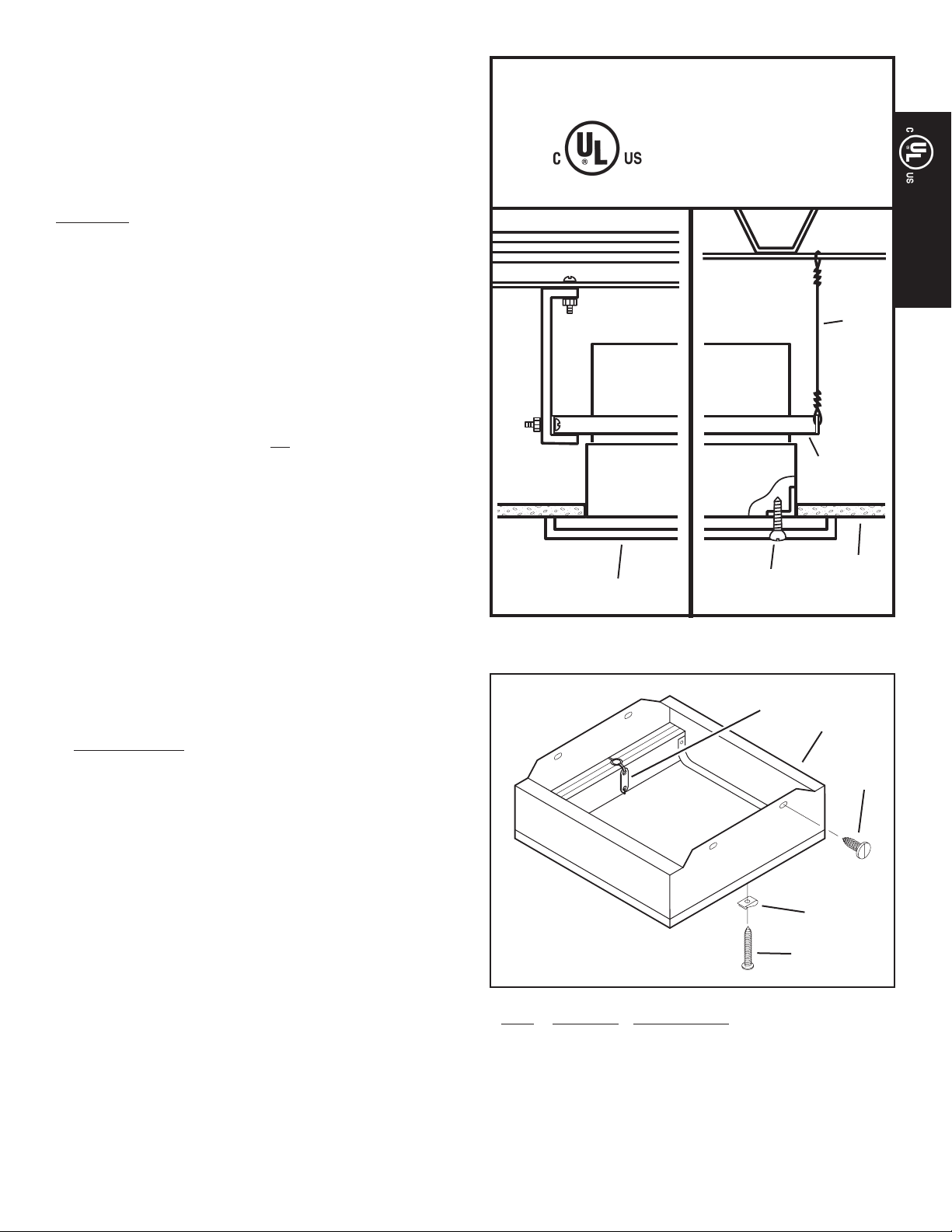
1. Plan installation so that ceiling penetration is located within
ceiling tiles or panels without necessitating cuts in any ceiling
suspension main runners or cross tees. If required, a maximum
of one runner or cross tee may be cut to accommodate desired
damper location. Cut ends must be supported by a minimum
12 steel wire gauge (3mm) vertical hanger wire.
2. Position radiation damper on the inlet side of the fan so that the
arrow in the damper will point UP in the nished installation.
Attach the damper to the fan using #8 (M4) sheet metal screws
(provided). There must be a minimum of two connections on each
of two opposite sides. Care must be taken to ensure that the
fasteners do not interfere with the closing of the damper curtain.
For best results, use mounting holes provided.
3. Mount fan/damper assembly to the deck or ceiling structure above
or adjacent to the assembly. If the assembly is hung from the
structure above, a minimum 12 steel wire gauge (3mm) hanger
wire must be used. There must be a minimum of two wires on
each of two opposite sides. If the assembly is directly mounted
to the adjacent structure, use #8 (M4) sheet metal screws or
1/4” (6mm) diameter bolts with nuts to mechanically fasten it
to the structure. Position fan/damper assembly so that the inlet
face of the radiation damper is ush with the nished surface of
the ceiling. Ceiling opening must be no larger than the inlet
opening of the damper.
4. New Construction
A housing mask has been provided to keep construction dust,
drywall spray, paint, etc. from damaging the radiation damper
of blower assembly.
a) Bend up the small tab of the mask.
b) Tuck the opposite side of the mask under one of the damper’s
grille mounting ears and push mask up into damper housing.
Note: Mask can be put in place before or after the blowers as-
sembly is installed.
Remove mask before installing grille or operating fan.
5. Attach the metal grille, supplied, over the inlet face of the radiation damper using #8 (M4) sheet metal screws (provided). There
must be a minimum of one screw on each of two opposite sides.
For best results, use mounting holes provided.
FAN
DAMPER
GRILLE
For replacement
parts telephone
1-800-558-1711
ITEM PART NO. DESCRIPTION
1 99523579 Fusible Link
2 99260485 Sheet Metal Nut
3 99170245 Damper Screw
4 99150573 Grille Screw
5 99523357 Radiation Damper
-- 98009908 Metal Grille
-- 97015727 Metal Duct Connector
GRILLE
SCREW
WIRE
MOUNTING
BRACKET
CEILING
1
5
3
2
4
99043769A
MODEL RD4
RADIATION DAMPER
INSTALLATION INSTRUCTIONS
For Use In 1, 2 or 3 Hour Rated Floor-Ceiling and Roof-Ceil-
ing Designs
Horizontal Mount Only
For Use With The Following Fan Models:
Fan Models
Broan HD50, HD80, 676, 684
NuTone HD50NT, HD80NT, 676NT, 684NT
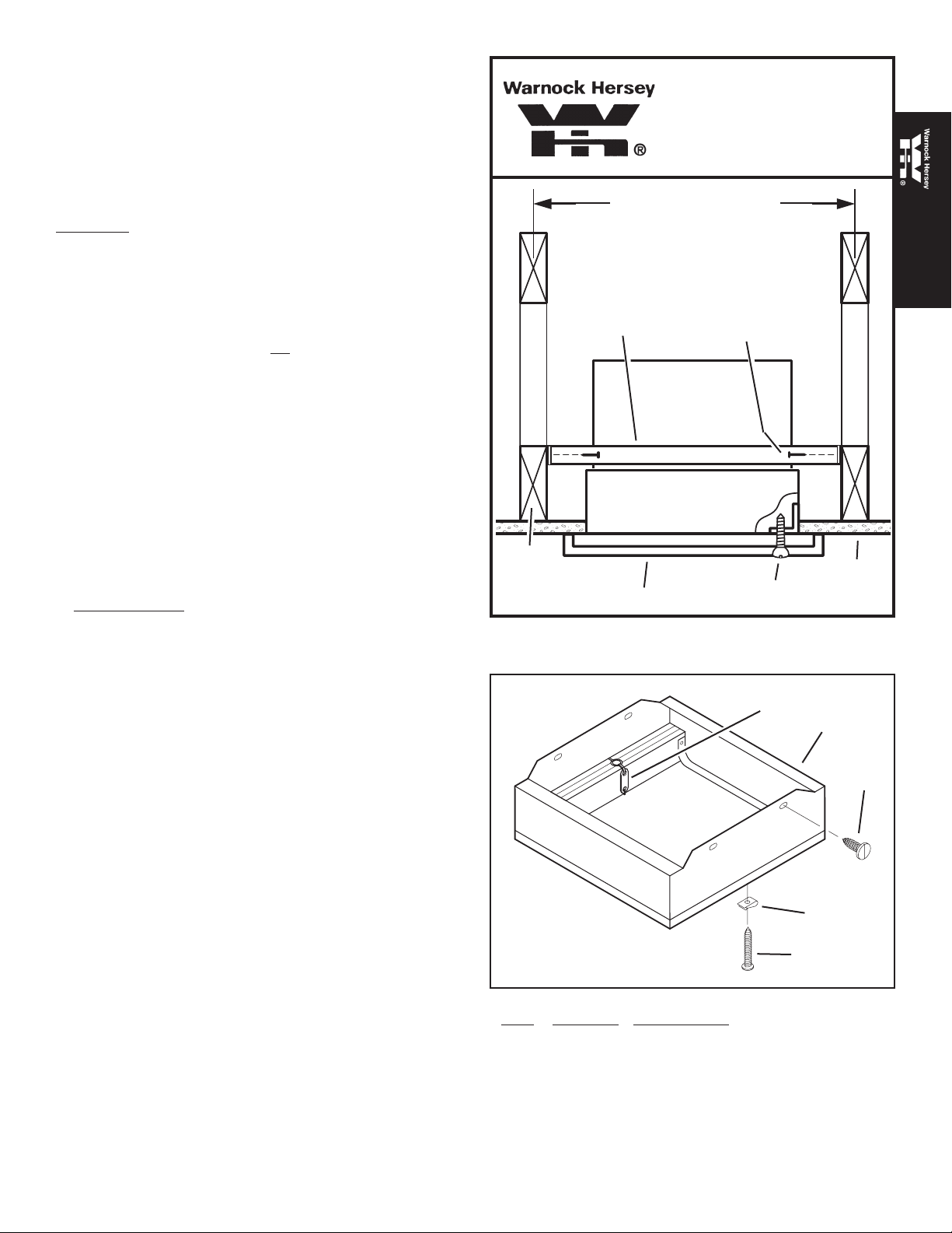
1. Position radiation damper on the inlet side of the fan so that the
arrow in the damper will point UP in the nished installation.
Attach the damper to the fan using #8 (M4) sheet metal screws
(provided). There must be a minimum of two connections on each
of two opposite sides. Care must be taken to ensure that the
fasteners do not interfere with the closing of the damper curtain.
For best results, use mounting holes provided.
2. Position fan/damper assembly so that the inlet face of the radia-
tion damper is ush with the nished surface of the ceiling. Fasten
fan/damper assembly to the building structure by driving #10 (M5)
minimum sheet metal screws or #8d minimum nails through the
fan mounting brackets and into the ceiling joists. There must
be a minimum of two fasteners on each of two opposite sides.
Ceiling opening must be no larger than the inlet opening of
the damper.
3. New Construction
A housing mask has been provided to keep construction dust,
drywall spray, paint, etc. from damaging the radiation damper
of blower assembly.
a) Bend up the small tab of the mask.
b) Tuck the opposite side of the mask under one of the damper’s
grille mounting ears and push mask up into damper housing.
Note: Mask can be put in place before or after the blowers as-
sembly is installed.
Remove mask before installing grille or operating fan.
4. Attach the metal grille, supplied, over the inlet face of the radia-
tion damper using #8 (M4) sheet metal screws (provided). There
must be a minimum of one screw on each of two opposite sides.
For best results, use mounting holes provided.
WARNOCK HERSEY LISTED
MOUNTING
BRACKET
WOOD
FRAMING
MEMBER
OR JOIST
WARNOCK HERSEY LISTING
INCLUDES DAMPER ONLY. IT
DOES NOT INCLUDE EXHAUST
FAN. DAMPERS MAY BE USED
WITH UL LISTED FAN MODELS
NOTED.
16” OR 24” ON CENTER
FASTENER
FAN
DAMPER
GRILLE
GRILLE SCREW
English
English
CEILING
1
5
3
For replacement
parts telephone
1-800-558-1711
ITEM PART NO. DESCRIPTION
1 99523579 Fusible Link
2 99260485 Sheet Metal Nut
3 99170245 Damper Screw
4 99150573 Grille Screw
5 99523357 Radiation Damper
-- 98009908 Metal Grille
-- 97015727 Metal Duct Connector
2
4
99043769A

INSTRUCCIONES DE INSTALACIÓN
REGULADOR DE RADIACIÓN
MODELO RD4
Clasicado para usarse en montajes de piso-cielo raso y de
techo-cielo raso de 1, 2 ó 3 horas
Sólo montaje horizontal
Para usarse con los ventiladores de los siguientes modelos:
Modelos de ventiladores
Broan HD50, HD80, 676, 684
NuTone HD50NT, HD80NT, 676NT, 684NT
CLASIFICADO
VEA LOS DETALLES EN LA
MARCA DE CLASIFICACIÓN
DE UL EN EL PRODUCTO
INCLUIDO
1. Planee la instalación de tal modo que la abertura en el cielo
raso quede ubicada entre los azulejos o paneles del cielo
raso sin necesidad de hacer cortes en las T transversales
ni en travesaños de suspensión. Si se requiere, puede
cortarse un máximo de una T o un travesaño para colocar
el regulador en la posición deseada. Los extremos cortados
deben soportarse con un alambre de suspensión vertical de
acero de calibre 12 (3 mm) como mínimo.
2. Coloque el regulador de radiación en el lado de entrada
Español
del ventilador, de modo que la echa del regulador apunte
hacia ARRIBA en la instalación terminada. Conecte el
regulador al ventilador usando tornillos autorroscantes #8
(M4) (incluidos). Debe haber un mínimo de dos conexiones
a cada uno de los dos lados opuestos. Debe tener cuidado
para asegurarse que los sujetadores no intereran con el
cierre de la cortina del regulador. Para obtener óptimos
resultados, use los oricios de montaje existentes.
3. Monte el conjunto del ventilador/regulador en la plataforma o
estructura del cielo raso que se encuentra arriba o adyacente
al conjunto. Si el conjunto se cuelga de la estructura de
arriba, debe utilizarse un alambre de suspensión de acero de
calibre 12 (3 mm) como mínimo. Debe haber un mínimo de
dos alambres en cada uno de los dos lados opuestos. Si el
conjunto se monta directamente en la estructura adyacente,
use tornillos autorroscantes #8 (M4) o pernos con tuercas
de 6 mm (1/4”) de diámetro para sujetar mecánicamente
el conjunto a la estructura de la edicación. Coloque el
conjunto de ventilador y regulador de tal modo que la cara
de entrada del regulador de radiación quede al ras con la
supercie terminada del cielo raso. La abertura del cielo
raso no debe ser más grande que la abertura de entrada
del regulador.
4. Nueva construcción
Se incluye una cubierta protectora para impedir la caída de
polvos de construcción, rocíos de yeso, pintura, etc. en el
regulador de radiación del conjunto del ventilador, los cuales
podrían dañarlo.
a) Doble hacia arriba la aleta pequeña de la cubierta
protectora.
b) Meta el lado opuesto de la cubierta protectora debajo
una de las orejetas de montaje de la rejilla del regulador.
Empuje la cubierta protectora hacia dentro de la caja del
regulador.
Nota: Se puede poner la cubierta protectora antes o después
de instalar el conjunto del ventilador.
Quite la cubierta protectora antes de instalar la rejilla o
de poner a funcionar el ventilador.
5. Conecte la rejilla de metal, suministrada, sobre la cara
de entrada del regulador de radiación usando tornillos
autorroscantes #8 (M4) (incluidos). Debe haber al menos un
tornillo en cada uno de los dos lados opuestos. Para obtener
óptimos resultados use los oricios de montaje existentes.
ALAMBRE
VENTILADOR
SOPORTE DE
MONTAGE
CIELO
RASO
REJILLA
REGULADOR
TORNILLO
DE REJILLA
1
5
2
Para pedir piezas de
repuesto llame al
1-800-558-1711
ARTÍCULO NÚM. DE PIEZA DESCRIPCIÓN
1 99523579 Enlace de fusible
2 99260485 Tuerca autorroscante
3 99170245 Tornillo del regulador
4 99150573 Tornillo de la rejilla
5 99523357 Regulador de radiación
-- 98009908 Rejilla de metal
-- 97015727 Ducto redondo de metal
4
3

INSTRUCCIONES DE INSTALACIÓN
REGULADOR DE RADIACIÓN
MODELO RD4
• Clasicado para usarse en montajes de piso-cielo raso y de
techo-cielo raso de 1, 2 ó 3 horas
• Sólo montaje horizontal
• Para usarse con los ventiladores de los siguientes modelos:
Modelos de ventiladores
Broan HD50, HD80, 676, 684
NuTone HD50NT, HD80NT, 676NT, 684NT
1. Coloque el regulador de radiación en el lado de entrada del
WARNOCK HERSEY LISTED
40,6 CM (16 PO) O
LA MENCIÓN EN WARNOCK
HERSEY INCLUYE SOLAMENTE
AL REGULADOR. NO INCLUYE
EL VENTILADOR DE ESCAPE.
LOS REGULADORES SE PUEDEN
USAR CON LOS MODELOS
INDICADOS DE VENTILADORES
MENCIONADOS EN UL.
61 CM (24 PO)
AL CENTRO
ventilador, de modo que la echa del regulador apunte
hacia ARRIBA en la instalación terminada. Conecte el
regulador al ventilador usando tornillos autorroscantes
#8 (M4) (incluidos). Debe haber un mínimo de dos
conexiones a cada uno de los dos lados opuestos. Debe
tener cuidado para asegurarse que los sujetadores no
intereran con el cierre de la cortina del regulador. Para
English
Español
obtener óptimos resultados, use los oricios de montaje
existentes.
2. Coloque el conjunto de ventilador y regulador de tal modo
que la cara de entrada del regulador de radiación quede
al ras con la supercie terminada del cielo raso. Sujete
el conjunto del ventilador y regulador a la estructura
del edicio con tornillos autorroscantes #10 (M5) como
mínimo, o con clavos #8d como mínimo, a través de los
soportes de montaje del ventilador y en las vigas del cielo
raso. Debe haber un mínimo de dos sujetadores en cada
uno de los dos lados opuestos. La abertura del cielo raso
no debe ser más grande que la abertura de entrada
del regulador.
3. Nueva construcción
Se incluye una cubierta protectora para impedir la caída
de polvos de construcción, rocíos de yeso, pintura, etc.
en el regulador de radiación del conjunto del ventilador,
los cuales podrían dañarlo.
a) Doble hacia arriba la aleta pequeña de la cubierta
protectora.
b) Meta el lado opuesto de la cubierta protectora debajo
una de las orejetas de montaje de la rejilla del regulador.
Empuje la cubierta protectora hacia dentro de la caja del
regulador.
Nota: Se puede poner la cubierta protectora antes o
después de instalar el conjunto del ventilador.
Quite la cubierta protectora antes de instalar la rejilla
o de poner a funcionar el ventilador.
4. Conecte la rejilla de metal, suministrada, sobre la cara
de entrada del regulador de radiación usando tornillos
autorroscantes #8 (M4) (incluidos). Debe haber al menos
un tornillo en cada uno de los dos lados opuestos. Para
obtener óptimos resultados use los oricios de montaje
existentes.
SOPORTE DE
MONTAJE
CONSTRUCCIÓN
DE MADERA
VENTILADOR
REGULADOR
REJILLA
SUJETADOR
TORNILLO
DE REJILLA
CIELO
RASO
1
5
2
Para pedir piezas de
repuesto llame al
1-800-558-1711
ARTÍCULO NÚM. DE PIEZA DESCRIPCIÓN
1 99523579 Enlace de fusible
2 99260485 Tuerca autorroscante
3 99170245 Tornillo del regulador
4 99150573 Tornillo de la rejilla
5 99523357 Regulador de radiación
-- 98009908 Rejilla de metal
-- 97015727 Ducto redondo de metal
4
3
 Loading...