

Page 1
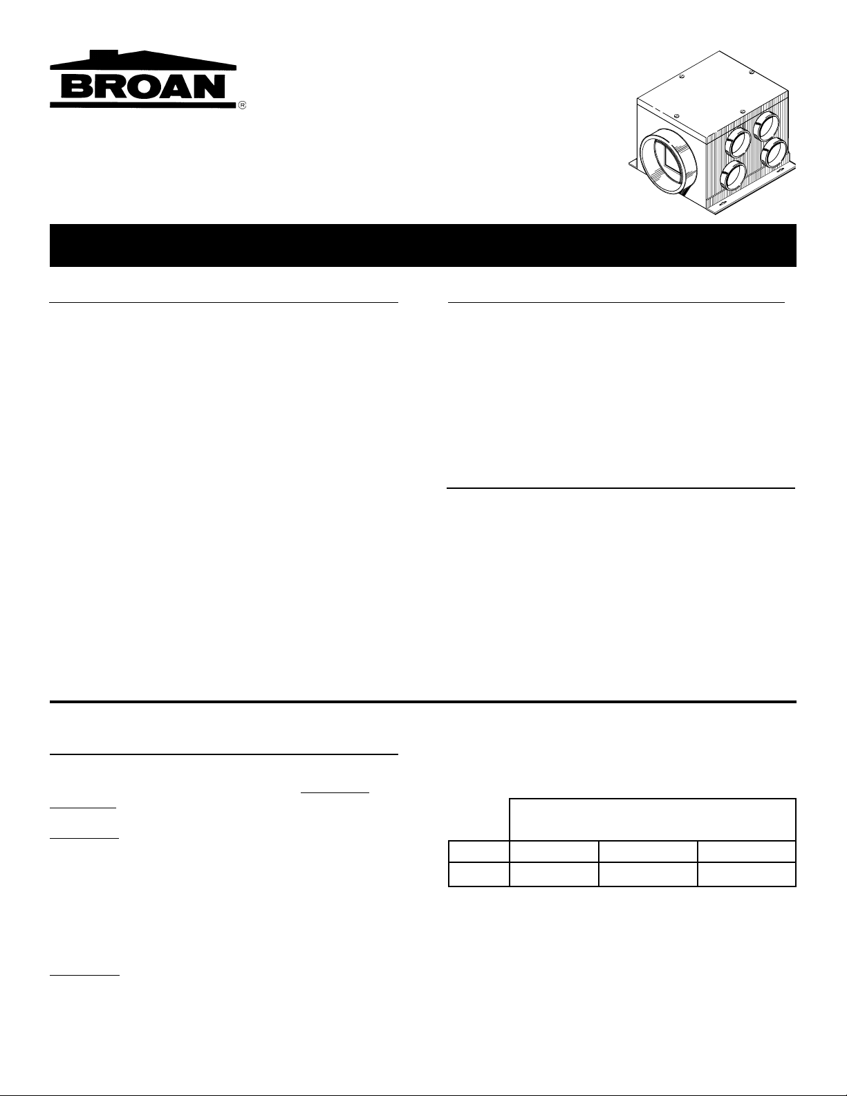
MODEL MP280
MULTI-PORT IN-LINE VENTILATOR
READ AND SAVE THESE INSTRUCTIONS
WARNING
TO REDUCE THE RISK OF FIRE, ELECTRIC SHOCK,
OR INJURY TO PERSONS, OBSERVE THE FOLLOWING:
1. Use this unit only in the manner intended by the manufacturer. If you have questions, contact the manufacturer at the address or telephone number listed below
the warranty.
2. Before servicing or cleaning unit, switch power off at
service panel and lock the service disconnecting means
to prevent power from being switched on accidentally.
When the service disconnecting means cannot be locked,
securely fasten a prominent warning device, such as a
tag, to the service panel.
3. Installation work and electrical wiring must be done by
qualified person(s) in accordance with all applicable
codes and standards, including fire-rated construction
codes and standards.
4. Sufficient air is needed for proper combustion and
exhausing of gases through the flue (chimney) of fuel
burning equipment to prevent backdrafting. Follow the
heating equipment manufacturer’s guideline and safety
standards such as those published by the National Fire
WARNING
Protection Association (NFPA), and the American Society for Heating, Refrigeration and Air Conditioning Engineers (ASHRAE), and the local code authorities.
5. When cutting or drilling into wall or ceiling, do not
damage electrical wiring and other hidden utilities.
6. Ducted fans must always be vented to the outdoors.
7. This unit must be grounded.
CAUTION
1. For general ventilating use only. Do not use to exhaust
hazardous or explosive materials and vapors.
2. To avoid motor bearing damage and noisy and/or unbalanced impellers, keep drywall spray, construction
dust, etc. off power unit.
3. If ventilator is installed in an unconditioned space
(such as an attic): Surround the ventilator with thermal
insulation - to minimize possible condensation.
4. Please read specification label on product for further
information and requirements.
PLAN THE INSTALLATION
Adequate ventilation requires that both intermittent and
continuous contamination be controlled.
Intermittent ventilation must be provided in the bathroom
and kitchen. The bathroom requires 8 air changes per hour.
(Multiply bathroom sq. footage by 1.1 for proper fan sizing)
The kitchen requires a minimum of 150 CFM capacity (71
l/s) when a ducted range hood is used. If a kitchen fan is
used, determine fan capacity by multiplying the room's sq.
footage by 2. All are run intermittently to control pollution at
the source.
Continuous ventilation, while the house is occupied, provides the flow of fresh air for good indoor air quality.
This ventilator is intended to for continuous operation,
supplying fresh air to the entire house.
RECOMMENDED VENTILATOR SIZING
DWELLING SIZE RANGE (Sq. Ftg.)
(include finished basement area)
MODEL
MP280
*AC/HR = Air Changes per Hour. Based on 8' ceilings.
SQ. FT. x 10.764 = M
.50 AC/HR* .35 AC/HR* .30 AC/HR*
4200 6000 7000
2
Page 2
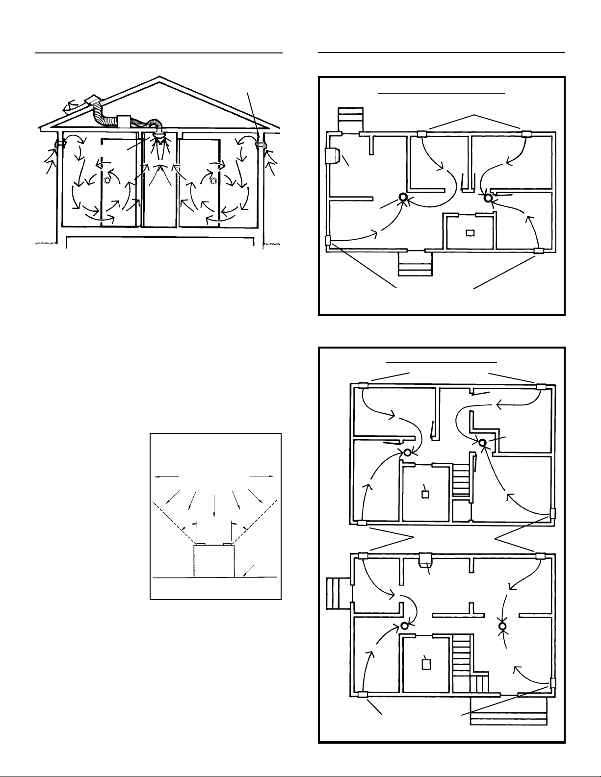
PLAN THE INSTALLATION
LOCATION OF DIFFUSERS & INLETS
FRESH AIR
STALE
AIR
VENTILATOR
DIFFUSER
INLET
FRESH
AIR
AIR FLOW IN TYPICAL INSTALLATION
VENTILATOR
The ventilator exhausts stale air. There are normally sufficient natural intake openings into a dwelling to admit fresh
outside air to be drawn in to replace the stale air. For better
control, fresh air inlets may be used.
The ventilator should be centrally located to keep ductwork
as short as possible. Locations for the ventilator include:
joists in an attic space or the basement, or a wall away from
the living areas.
EXHAUST
DIFFUSERS
(Available separately)
Exhaust diffusers regulate
the flow of fresh air drawn
through the house.
Exhaust diffusers should
be mounted in the ceilings or high on the wall.
For best performance, exhaust diffusers should be
mounted in a central location. An exhaust diffuser
should not be installed
near a cooking area. (see
figure)
COOKING AREA
Do not install
above or inside
this area
o
45
Cooking
Equipment
o
45
Floor
SINGLE-STORY HOME
DUCTED
KITCHEN
RANGE HOOD
DIFFUSER
DIFFUSER
FRESH AIR INLETS
DIFFUSER
DUCTED
BATH FAN
FRESH AIR INLETS
TWO-STORY HOME
FRESH AIR INLETS
DIFFUSER
SECOND
FLOOR
DUCTED
BATH FAN
FRESH AIR INLETS
DUCTED
KITCHEN
RANGE HOOD
FRESH AIR INLETS (Available separately)
For best control of fresh air in a room, install a fresh air inlet.
The number of inlet vents depends on the floor plan.
Consider the rooms/areas through which fresh air should
flow toward the exhaust diffuser(s).
Vents should be located in outside walls, preferably near
the ceiling and approximately the same distance from a
diffuser. Vents should be separated from diffusers far
enough to allow fresh air to mix with room air before being
exhausted.
DIFFUSER
DUCTED
BATH FAN
FRESH AIR INLETS
DIFFUSER
FIRST FLOOR
Page 3

INSTALL FRESH AIR INLETS
1. Mount all fresh air inlets in chosen locations during
rough-in construction. Follow directions packed with
inlets.
MOUNT THE VENTILATOR
CONNECT DUCTWORK
FROM
DIFFUSERS
OUTLET
SIDE
DUCT
TAPE
OR
CLAMP
CEILING
JOISTS
CEILING
JOISTS
OR
2 X 4
FRAMING
6" ROUND
INSULATED
FLEXIBLE
DUCT
TO ROOF OR
WALL CAP
1. Run 4" insulated, flexible ductwork from ventilator inlet
to diffuser location(s) and 6" flexible ductwork from
ventilator outlet to roof or wall cap.Outlet side is marked
with label.
2. To minimize condensation inside of ductwork in the attic, cover ductwork with additional insulation. Also, avoid
forming condensation traps in the ductwork runs.
3. Seal ductwork to ventilator and roof or wall cap with duct
tape or clamp (available separately)
4.
If some ventilator inlets will not be used:
Place the inlet
cover(s) (provided) over the unused inlet(s) and tape
them in place.
WIRE THE VENTILATOR
WARNING: DISCONNECT POWER AT SERVICE
ENTRANCE AND LOCK OUT SERVICE PANEL TO
PREVENT POWER FROM BEING SWITCHED ON
ACCIDENTALLY.
GROUND
WIRE
BLACK
WIRING ADAPTER
PLATE
2 X 4
FRAMING
1. Add framing to ceiling joists as shown.
2. Set ventilator in place and screw it to framing with screws
provided. Ventilator may also be hung from ceiling joists
or rafters with hanging straps (available separately).
WHITE
GROUND
(Green or
Bare Wires)
120 VAC
LINE IN
BLACK
ON/OFF
SWITCH
BLACK
Use an ON/OFF switch to control the in-line ventilator.
Accessory timers and humidity controls are also available.
1. Remove the wiring adapter plate.
2. Attach power cable to wiring adapter plate using U.L./
CSA approved connector.
3. Connect black to black, white to white, and green or bare
wire to green ground screw.
4. Replace wiring adapter plate. Make sure tab on housing
slides through slot in plate.
Page 4

INSTALL EXHAUST DIFFUSERS USE AND CARE
4" ROUND
INSULATED
TO
VENTILATOR
CEILING
DRYWALL
FLEXIBLE DUCT
DUCT
TAPE
OR
CLAMP
DIFFUSER
Follow instructions packed with diffuser(s). General instructions:
1. Cut hole(s) in ceiling drywall and install diffuser(s).
2. Connect insulated ductwork to diffuser(s) and use duct
tape or clamp (available separately) to seal connection(s).
3. Rotate center of diffuser(s) counterclockwise to fully
open for maximum air flow. Reduce air flow by rotating
center of diffuser(s) clockwise to desired opening. A
balancing damper (available separately) can be used to
adjust airflow.
SERVICE PARTS
WARNING: DISCONNECT ELECTRICAL POWER SUPPLY AND LOCK OUT SERVICE PANEL BEFORE CLEANING OR SERVICING THIS UNIT.
CLEANING
A continuously operating in-line ventilator needs to be
cleaned once a year to assure proper performance.
Remove cover and carefully vacuum blower and inside of
housing. Be careful not to bend or otherwise damage
blower wheel.
Diffusers and intake vents can be vacuumed and/or wiped
clean with a damp cloth.
MOTOR LUBRICATION
The motor is permanently lubricated. Do not oil or disassemble motor.
1
13
18
17
10
16
Model MP280
KEY PART DESCRIPTION
NO. NO.
1 99170245 Screw, #8B x 3/8" (8 required)*
2 97011414 Housing Assembly (includes Key No. 7)
3 98005512 Wiring Adapter Plate
4 99150471 Ground Screw, #10-32 x 1/2" (2 required)
5 97006081 Wiring Harness
6 99150591 Screw, #10 x 7/8" (4 required)*
7 99420470 Grille Nut (4 required)
8 98005513 Outlet Box Cover
9 99400035 Strain Relief Bushing
10 97011423 Blower Wheel
11 97011346 Blower Housing
12 99100484 Motor Mounting Rubber (3 required)
13 97011415 Motor (includes Key No. 16)
14 98005405 Blower Mounting Channel
15 99150536 Screw, 1/4-20 x 5/16" (3 required)*
16 97011418 Capacitor w/ Cover
17 99260477 Whiz Nut, 1/4-20 (7 required)*
18 97011419 Cover
19 99110942 Inlet Cover (covers unused inlet ports) (2 req.)
** 97011417 Blower Assembly Complete (includes Key
* Standard Hardware - May be purchased locally.
** Not shown assembled.
Broan warrants to the original consumer purchaser of its products that such products will be free from defects in materials or workmanship for a period of one year from the date of original purchase. THERE
ARE NO OTHER WARRANTIES, EXPRESS OR IMPLIED, INCLUDING, BUT NOT LIMITED TO, IMPLIED WARRANTIES OF MERCHANTABILITY OR FITNESS FOR A PARTICULAR PURPOSE.
During this one-year period, Broan will, at its option, repair or replace, without charge, any product or part which is found to be defective under normal use and service.
THIS WARRANTY DOES NOT EXTEND TO FLUORESCENT LAMP STARTERS AND TUBES. This warranty does not cover (a) normal maintenance and service or (b) any products or parts which have
been subject to misuse, negligence, accident, improper maintenance or repair (other than by Broan), faulty installation or installation contrary to recommended installation instructions.
The duration of any implied warranty is limited to the one-year period as specified for the express warranty. Some states do not allow limitation on how long an implied warranty lasts, so the above limitation
may not apply to you.
BROAN’S OBLIGATION TO REPAIR OR REPLACE, AT BROAN’S OPTION, SHALL BE THE PURCHASER’S SOLE AND EXCLUSIVE REMEDY UNDER THIS WARRANTY. BROAN SHALL NOT BE
LIABLE FOR INCIDENTAL, CONSEQUENTIAL OR SPECIAL DAMAGES ARISING OUT OF OR IN CONNECTION WITH PRODUCT USE OR PERFORMANCE. Some states do not allow the exclusion
or limitation of incidental or consequential damages, so the above limitation or exclusion may not apply to you.
This warranty gives you specific legal rights, and you may also have other rights, which vary from state to state. This warranty supersedes all prior warranties.
To qualify for warranty service, you must (a) notify Broan, (b) give the model number and part identification and (c) describe the nature of any defect in the product or part. At the time of requesting warranty
service, you must present evidence of the original purchase date.
No.s 10 thru 17)
Always order replacement parts by “Part No, - not by “Key No.”
BROAN ONE YEAR LIMITED WARRANTY
In the U.S., contact: Broan-NuTone LLC, A Nortek Company, 926 West State Street, Hartford, WI 53027 (1-800-637-1453)
In Canada, contact: Broan-NuTone Canada, A Nortek Company, 1140 Tristar Drive Mississauga, Ontario L5T 1H9 (905-670-2500)
6
14
17
11
1
9
8
2
1
4
5
7
3
12
15
19
99041952G
 Loading...