

Broan HRVH100S, ERVH100S Installation Manual
VB0235
INSTALLATION GUIDE
MODELS HRVH100S AND ERVH100S
These products earned the ENERGY STAR® by meeting strict energy efficiency guidelines set by Natural Resources
Canada and the US EPA. They meet ENERGY STAR requirements only when used in Canada.
! !
RESIDENTIAL INDOOR USE ONLY
READ AND SAVE THESE INSTRUCTIONS
Broan-NuTone LLC; Hartford, Wisconsin www.broan.com 800-543-3055
REGISTER YOUR PRODUCT ONLINE AT: www.broan.com/register
For additional information - visit www.broan.com
22734 rev. 03
ABOUT THIS GUIDE
Please take note that this manual uses the following symbols to emphasize particular information:
!
WARNING
Identifies an instruction which, if not followed, might cause serious personal injuries including possibility of death.
CAUTION
Identifies an instruction which, if not followed, may severely damage the unit and/or its components.
NOTE: Indicates supplementary information needed to fully complete an instruction.
ABOUT THESE UNITS
LIMITATION
For residential (domestic) installation only. Installation work and electrical wiring must be done by a qualified person(s) in accordance with
all applicable codes and standards, including fire-rated construction codes and standards.
WARNING
!
TO REDUCE THE RISK OF FIRE, ELECTRIC SHOCK, OR INJURY TO PERSON(S) OBSERVE THE FOLLOWING:
1. Use this unit only in the manner intended by the manufacturer. If you have questions, contact the manufacturer at the address or
telephone number listed in the warranty.
2. We recommend that your unit be inspected by a specialized technician once a year.
3. Before servicing or cleaning the unit, disconnect power cord from electrical outlet.
4. This unit is not designed to provide combustion and/or dilution air for fuel-burning appliances.
5. When cutting or drilling into wall or ceiling, do not damage electrical wiring and other hidden utilities.
6. Do not use this unit with any solid-state speed control device other than following optional main and auxiliary wall controls:
Optional Main Controls Optional Auxiliary Controls
VT8W, VT7W, VT4W and VT6W 59W and VB60W
7. This unit must be grounded. The power supply cord has a 3-prong grounding plug for your personal safety. It must be plugged into a
mating 3-prong grounding receptacle, grounded in accordance with the national electrical code and local codes and ordinances. Do
not remove the ground prong. Do not use an extension cord.
8. Do not install in a cooking area or connect directly to any appliances.
9. Do not use to exhaust hazardous or explosive materials and vapors.
10. When performing installation, servicing or cleaning the unit, it is recommended to wear safety glasses and gloves.
11. Due to the weight of the unit, two installers are recommended to perform installation.
12. When applicable local regulations comprise more restrictive installation and/or certification requirements, the aforementioned
requirements prevail on those of this document and the installer agrees to conform to these at his own expenses.
CAUTION
1. To avoid prematurate clogged filters, turn OFF the unit during construction or renovation.
2. Please read specification label on product for further information and requirements.
3. Be sure to duct air outdoor – Do not intake/exhaust air into spaces within walls or ceiling or into attics, crawl spaces, or garage.
4. Intended for residential installation only in accordance with the requirements of NFPA 90B.
5. Do not run any air ducts directly above or closer than 2 ft to any furnace or its supply plenum, boiler, or other heat producing appliance.
If a duct has to be connected to the furnace return plenum, it must be connected not closer than 9’ 10” from this plenum connection to
the furnace.
6. The ductwork is intended to be installed in compliance with all applicable codes.
7. When leaving the house for a long period of time (more than two weeks), a responsible person should regularly check if the unit
operates adequately.
8. If the ductwork passes through an unconditioned space (e.g.: attic), the unit must operate continuously except when performing
maintenance and/or repair. Also, the ambient temperature of the house should never drop below 65°F.
2
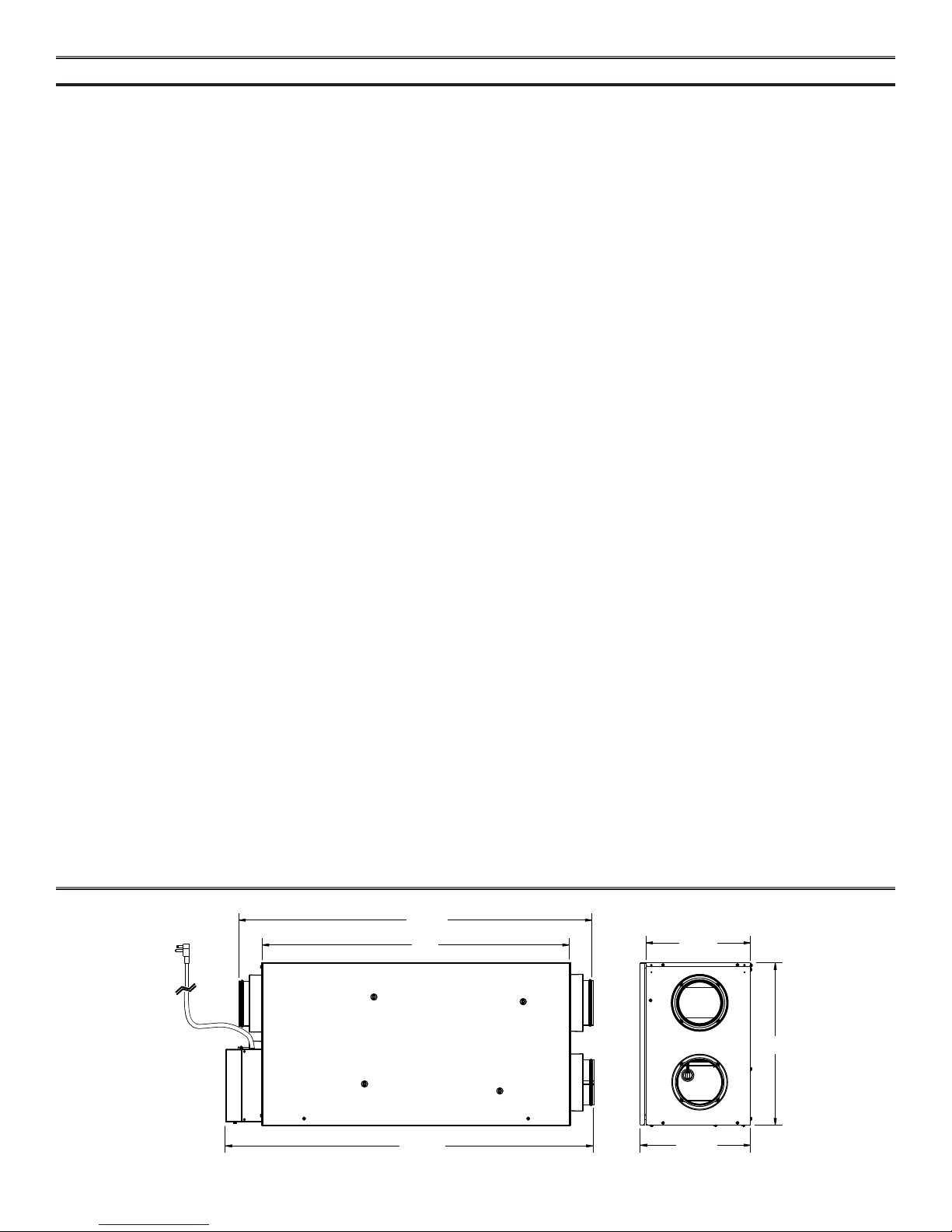
TABLE OF CONTENTS
1. DIMENSIONS . . . . . . . . . . . . . . . . . . . . . . . . . . . . . . . . . . . . . . . . . . . . . . . . . . 3
YPICAL INSTALLATIONS. . . . . . . . . . . . . . . . . . . . . . . . . . . . . . . . . . . . . . . . . . . . . . 4
2. T
2.1 FULLY DUCTED SYSTEM . . . . . . . . . . . . . . . . . . . . . . . . . . . . . . . . . . . . . . . . . . . . . . . 4
2.2 CENTRAL DRAW POINT . . . . . . . . . . . . . . . . . . . . . . . . . . . . . . . . . . . . . . . . . . . . . . . . 4
2.3 SIMPLIFIED INSTALLATION . . . . . . . . . . . . . . . . . . . . . . . . . . . . . . . . . . . . . . . . . . . . . . . 4
3. INSTALLATION . . . . . . . . . . . . . . . . . . . . . . . . . . . . . . . . . . . . . . . . . . . . . . . . 5-11
3.1 INSPECT THE CONTENT OF THE BOX . . . . . . . . . . . . . . . . . . . . . . . . . . . . . . . . . . . . . . . . . . 5
3.2 TOOLS AND MATERIAL . . . . . . . . . . . . . . . . . . . . . . . . . . . . . . . . . . . . . . . . . . . . . . . . 6
3.3 LOCATING THE UNIT . . . . . . . . . . . . . . . . . . . . . . . . . . . . . . . . . . . . . . . . . . . . . . . . . 6
3.4 PLANNING OF THE DUCTWORK . . . . . . . . . . . . . . . . . . . . . . . . . . . . . . . . . . . . . . . . . . . . . 6
3.5 INSTALLING NON-INSULATED DUCTS AND DIFFUSERS . . . . . . . . . . . . . . . . . . . . . . . . . . . . . . . . . . 7-9
3.5.1 FULLY DUCTED SYSTEM . . . . . . . . . . . . . . . . . . . . . . . . . . . . . . . . . . . . . . . . . . . . . . . . . . 7
3.5.2 CENTRAL DRAW POINT . . . . . . . . . . . . . . . . . . . . . . . . . . . . . . . . . . . . . . . . . . . . . . . . . . 8
3.5.3 SIMPLIFIED INSTALLATION. . . . . . . . . . . . . . . . . . . . . . . . . . . . . . . . . . . . . . . . . . . . . . . . . . 9
3.6 INSTALLING INSULATED FLEXIBLE DUCTS . . . . . . . . . . . . . . . . . . . . . . . . . . . . . . . . . . . . . . . 10
3.6.1 CONNECTION TO THE UNIT PORTS . . . . . . . . . . . . . . . . . . . . . . . . . . . . . . . . . . . . . . . . . . . . .10
3.6.2 LOCATING EXTERIOR PORTS . . . . . . . . . . . . . . . . . . . . . . . . . . . . . . . . . . . . . . . . . . . . . . . .10
3.7 CONNECTING INSULATED DUCTS TO EXTERIOR PORTS . . . . . . . . . . . . . . . . . . . . . . . . . . . . . . . . . 11
3.8 INSTALLING TANDEM® TRANSITION KIT . . . . . . . . . . . . . . . . . . . . . . . . . . . . . . . . . . . . . . . . 11
3.9 CONNECTING THE DRAIN . . . . . . . . . . . . . . . . . . . . . . . . . . . . . . . . . . . . . . . . . . . . . . 11
4. CONTROLS . . . . . . . . . . . . . . . . . . . . . . . . . . . . . . . . . . . . . . . . . . . . . . . . . 12-14
4.1 INTEGRATED CONTROL . . . . . . . . . . . . . . . . . . . . . . . . . . . . . . . . . . . . . . . . . . . . . . . 12
4.2 BOOTING SEQUENCE . . . . . . . . . . . . . . . . . . . . . . . . . . . . . . . . . . . . . . . . . . . . . . . . 12
4.3 SETTING EXTENDED DEFROST. . . . . . . . . . . . . . . . . . . . . . . . . . . . . . . . . . . . . . . . . . . . 12
4.4 ELECTRICAL CONNECTION TO OPTIONAL WALL CONTROLS . . . . . . . . . . . . . . . . . . . . . . . . . . . . . .13-14
4.4.1 ELECTRICAL CONNECTION TO VT8W MAIN WALL CONTROL. . . . . . . . . . . . . . . . . . . . . . . . . . . . . . . . . .13
4.4.2 ELECTRICAL CONNECTION TO VT7W MAIN WALL CONTROL. . . . . . . . . . . . . . . . . . . . . . . . . . . . . . . . . .13
4.4.3 ELECTRICAL CONNECTION TO VT4W MAIN WALL CONTROL. . . . . . . . . . . . . . . . . . . . . . . . . . . . . . . . . .13
4.4.4 ELECTRICAL CONNECTION TO VT6W MAIN WALL CONTROL. . . . . . . . . . . . . . . . . . . . . . . . . . . . . . . . . .13
4.4.5 ELECTRICAL CONNECTION TO OPTIONAL AUXILIARY WALL CONTROLS . . . . . . . . . . . . . . . . . . . . . . . . . . . . . .14
5. ELECTRICAL CONNECTION TO THE FURNACE . . . . . . . . . . . . . . . . . . . . . . . . . . . . . . . . . . . 15
IRING DIAGRAM . . . . . . . . . . . . . . . . . . . . . . . . . . . . . . . . . . . . . . . . . . . . . . . 16
6. W
ALANCING THE UNIT. . . . . . . . . . . . . . . . . . . . . . . . . . . . . . . . . . . . . . . . . . . . . . 17
7. B
ERVICE PARTS . . . . . . . . . . . . . . . . . . . . . . . . . . . . . . . . . . . . . . . . . . . . . . . . 18
8. S
ROUBLESHOOTING . . . . . . . . . . . . . . . . . . . . . . . . . . . . . . . . . . . . . . . . . . . . . 19-20
9. T
1. DIMENSIONS
VK0086A
7
37
33"
39 /8"
/8"
11 ¼"
7
/16"
17
7
/8"
11
3
2. TYPICAL INSTALLATIONS
Use the following illustrations as guidelines to help you decide on how the unit will be installed.
All the units should be hung from the joists.
In every case, bathroom fans and a range hood could be used to exhaust stale air. Also, for homes with more than one level, we recommend
one exhaust register at the highest level.
There are 3 installation methods: Fully Ducted System, Central Draw Point and Simplified Installation.
NOTE: An electrical outlet has to be available within 3 feet of the unit.
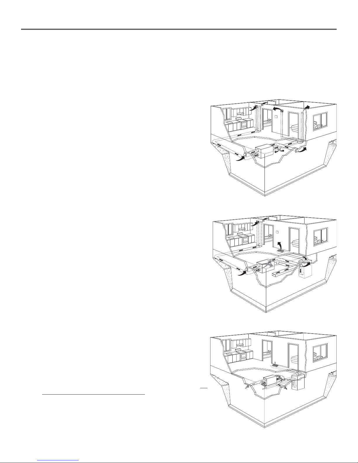
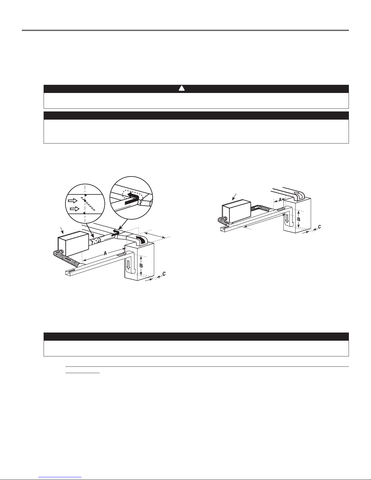
2.1 FULLY DUCTED SYSTEM (PRIMARILY FOR HOMES WITH RADIANT HOT WATER OR ELECTRIC BASEBOARD HEATING)
Stale air coming from the register located at the highest level of the
house is exhausted to the outdoor. Fresh air from outdoor is filtered and
supplied by the register located in the lowest liveable level.
Homes with more than one level require at least one exhaust register at
the highest level.
See figure at right.
2.2 CENTRAL DRAW POINT (CONNECTION TO A FORCED AIR SYSTEM)
Stale air coming from the register located at the highest level of the
house is exhausted to the outdoor. Fresh air from outdoor is filtered and
supplied to the return (plenum) or the supply duct of the forced air unit.
See figure at right.
For this type of installation, it is not essential that the forced air system
blower runs when the unit is in operation, but we recommend it.
NOTE: Home with multiple forced air systems should have one unit on
each system.
2.3 SIMPLIFIED INSTALLATION (CONNECTION TO A FORCED AIR SYSTEM)
Stale air is exhausted to the outdoor. Fresh air from outdoor is filtered
and supplied to the return (plenum) or the supply duct of the forced air
unit.
See figure at right.
To avoid cross-contamination and achieve the highest efficiencies, the
forced air system blower must always be ON.
NOTE: Home with multiple forced air systems should have one unit on
each system.
VH0024
VH0025
VH0093
4
3. INSTALLATION
3.1 INSPECT THE CONTENT OF THE BOX
NOTE: Before proceeding to the installation, check the content of the box. Remove all packaging material from the unit.
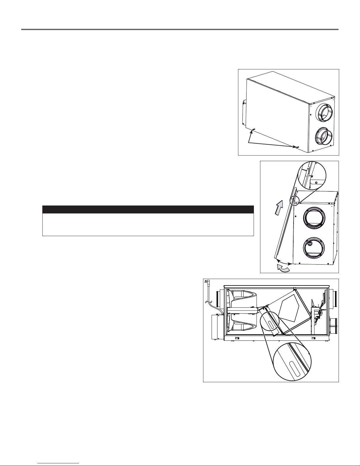
• Inspect the exterior of the unit for shipping damage. Ensure that there is no damage to the door, ports, power cord, etc.
• Using a Phillips or a Robertson screwdriver, loosen both door screws (A).
NOTE: The screws will stay attached to the door.
A
VD0302
• Open (B) and lift out (C) the door.
CAUTION
In order to prevent damages to the door hooks, do not open completely the
unit door; tilt it about 3" from the unit base and lift it up. See illustration at
right.
• Remove the transport tape over the heat or energy recovery core
of the unit.
• Inspect the inside of the unit for damage. Ensure that blower
assembly, heat or energy recovery core, core filters, insulation,
dampers, prefilter and HEPA filter, etc. are all intact, then reinstall
the door.
NOTE: Write the installation date on the HEPA filter frame for future
reference (see illustration at right).
C
B
VD0303A
TOP
DESSUS
FRONT
AVANT
Instal. date:
Date d’instal. :
__ / __ / ____
±3”
21293
FRONT
AVANT
Instal. date:
Date d’instal. :
__ / __ / ____
VD0322
5
3. INSTALLATION (CONT’D)
3.2 TOOLS AND MATERIAL
Following are the tools and material needed:
• Phillips no. 2 or Robertson no. 2 screwdriver
• Small flat blade screwdriver (for wall control connection)
• Wire stripper (for wall control connection)
• Hammer and flat blade screwdriver (for plenum or supply furnace duct connection installation only, to make holes in existing
metal duct)
• Scissors or utility knife (to cut duct tape)
• Measuring tape
• Duct tape
• Tin snips or metal shear (for plenum or supply furnace duct connection installation only, to cut ductwork)
• Aluminum duct tape (for plenum connection installation only)
• Jig saw
• Caulking gun and caulking.
3.3 LOCATING THE UNIT
Choose an appropriate location for the unit.
• Within an area of the house where the ambient temperature is kept between 50°F and 104°F.
• Away from living areas (dining room, living room, bedroom), if possible.
• So as to provide easy access to the interior of the unit, for maintenance.
• Close to an exterior wall, so as to limit the length of the insulated flexible duct to and from the unit.
• Away from hot chimneys and other fire hazards.
• Allow for a power source (standard 3-prong grounding outlet).
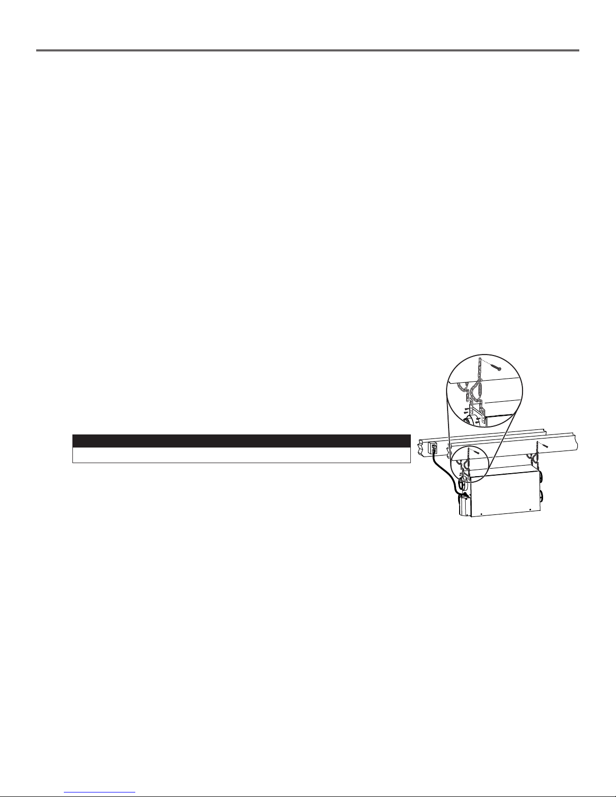
• FOR HRV UNITS ONLY: Close to a drain. If no drain is close by, use a pail to collect
run-off.
Hang the unit with the four hooks, chains and springs provided. See illustration at right.
Make sure the unit is level.
3.4 PLANNING OF THE DUCTWORK
• Keep it simple. Plan for a minimum of bends and joints.
• Keep the length of insulated ducts to a minimum.
• Do not ventilate crawl spaces or cold rooms. Do not attempt to recover the exhaust air from a dryer or a range hood. This
would cause clogging of the filters and recovery module.
• If the house has two floors or more, be sure to plan for at least one exhaust register on the highest lived-in level.
CAUTION
VD0305
6
3. INSTALLATION (CONT’D)
3.5 INSTALLING NON-INSULATED DUCTS AND DIFFUSERS
3.5.1 FULLY DUCTED SYSTEM (AS ILLUSTRATED IN SECTION 2.1)
Never install a stale air exhaust diffuser in a closed room where a combustion device operates, such as a
gas furnace, a gas water heater or a fireplace.
Stale air exhaust ductwork
• Install the stale air exhaust diffuser in the main area where the contaminants are produced: kitchen, living room, etc. Position
the diffuser as far from the stairway as possible and in such a way that the air circulates in all the lived-in spaces in the house.
If desired, you can install another diffuser (sold separately).
• If a diffuser is installed in the kitchen, it must be located at least 4 feet from the range.
• Install the diffuser 6 to 12 inches from the ceiling on an interior wall OR install it in the ceiling.
Fresh air distribution ductwork
• Install the fresh air distribution diffuser in a large, open area in the lowest level to ensure the greatest possible air circulation.
• Keep in mind that the fresh air diffuser must be located as far as possible from the stale air diffuser. If desired, you can install
another diffuser.
• Install the diffuser either in the ceiling OR 6 to 12 inches from the ceiling on an interior wall. (The cooler air will then cross the
upper part of the room and mix with room air, before descending to occupant’s level.)
• If a register must be floor installed, direct the airflow up the wall.
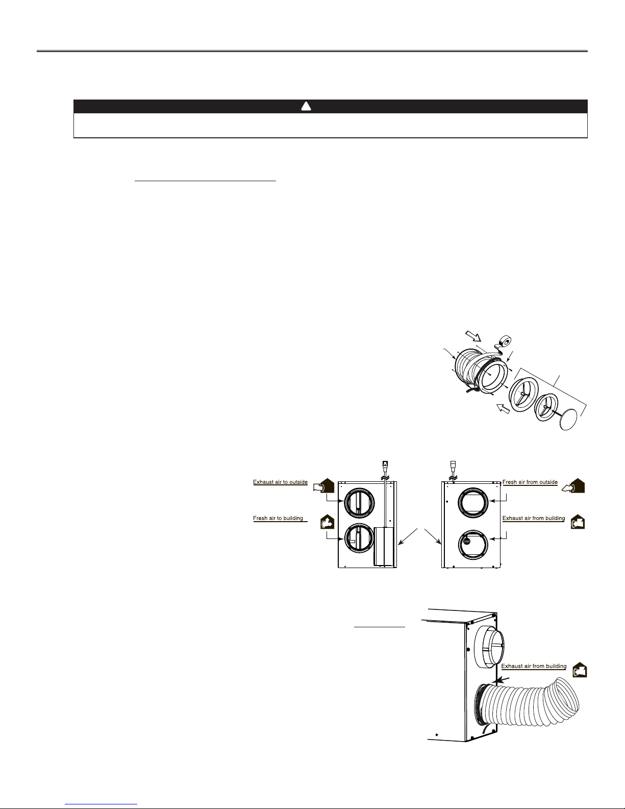
HOW TO CONNECT THE FLEXIBLE DUCTS TO THE DIFFUSERS
Once the diffusers location is determined, cut out 5¼” diameter hole.
Run one end of the flexible duct through the hole and fix it to the diffuser base (1),
using a tie wrap and duct tape. Assemble the diffuser base to the wall (or ceiling)
using its 4 no. 8 x 3/4” screws. Then, slide in the diffuser (2).
See illustration at right.
!
WARNING
Ø 5¼”
1
2
UNIT PORTS IDENTIFICATION
Aire de salida hacia el exterior
Each unit port has an identification label
beside it to avoid wrong duct connections to
the unit. Always refer to these labels before
Aire fresco hacia el interior
DOOR
performing any duct and port connection.
VJ0106
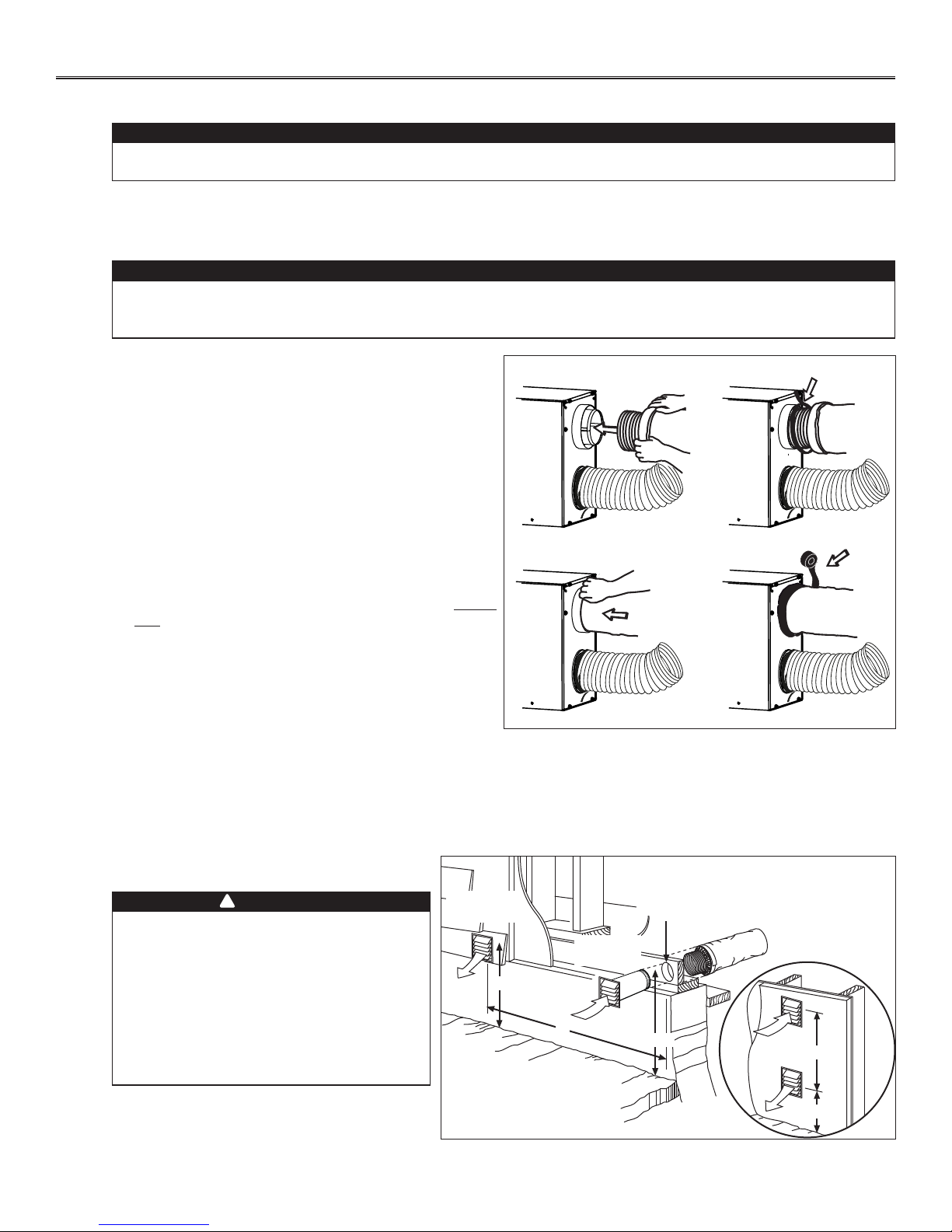
HOW TO CONNECT THE FLEXIBLE DUCTS TO THE UNIT PORTS
Both flexible ducts attached to the diffusers must be connected to the bottom ports of
the unit. When facing the unit door, the fresh air to building port is located on left side
and the exhaust air from building port is on the right side. Refer to the identification
labels affixed beside each unit ports. Using tie wrap, attach the fresh air to building
duct to its corresponding port, then do the same for the exhaust air to building duct
and port. See illustration at right.
NOTE: Use an insulated duct if the duct will have to go through a space where it is
possible to experience extreme temperature conditions (eg: in northern area,
unheated attic in winter or uncooled attic in southern area). Also, if you plan to
stop the unit for more than 12 hours, we recommend to cover the duct with R12
insulation.
VJ0094A
Aire fresco desde el exterior
UNIT
Aire de salida desde el interior
RIGHT SIDE OF THE UNIT
Aire de salida desde el interior
VJ0107
7
3. INSTALLATION (CONT’D)
VJ0108
3.5 INSTALLING NON-INSULATED DUCTS AND DIFFUSERS (CONT’D)
3.5.2 C
ENTRAL DRAW POINT (AS ILLUSTRATED IN SECTION 2.2)
Stale air exhaust ductwork
Same as for Fully Ducted System, described in step 3.5.1
Fresh air distribution ductwork
When performing duct connections, always use approved tools and materials. Respect all corresponding
laws and safety regulations. Please refer to your local building code.
When performing connection to the furnace supply duct, this duct must be sized to support the additional
air flow produced by the HRV/ERV. Also, use a metal duct with a backdraft damper to prevent the risk of
overheating the HRV/ERV.
!
WARNING
CAUTION
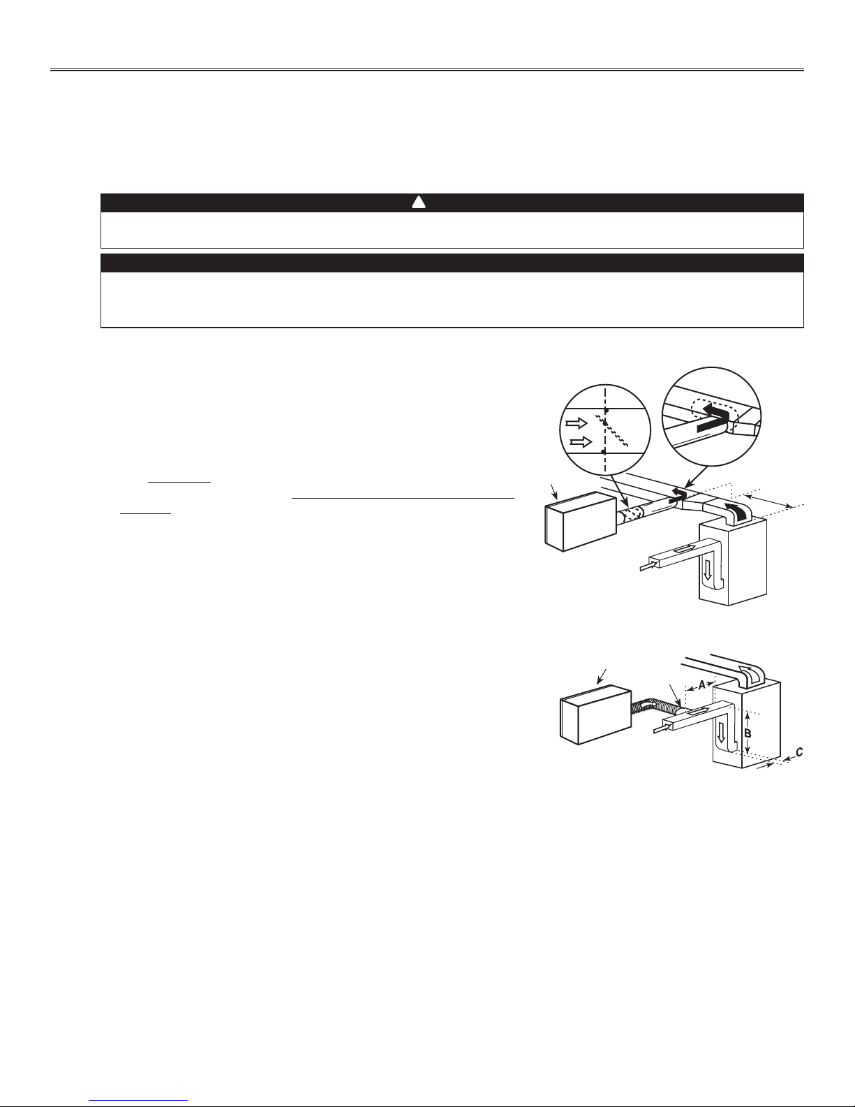
There are 2 methods for connecting the unit to the furnace:
Method 1: Supply side connection
• Cut an opening into the furnace supply duct at least 18” from the furnace.
• Connect this opening to the fresh air distribution port of the HRV/ERV
NIT DOOR
(use metal duct, see figure at right).
U
• Make sure that the HRV/ERV duct forms an elbow inside the furnace
ductwork.
• If desired, interlock (synchronize) the furnace blower operation with the
HRV/ERV operation (see Section 5).
Method 2: Return side connection
• Locate the opening for fresh air ductwork on the forced air unit return duct at a
minimum linear distance of 9’ 10” upstream (from forced air unit drop: A+B+C).
Cut out a 5” Ø hole in this location, using metal shear.
• Use a metal transition to connect the unit duct to the forced air unit return duct.
• Attach the other end of the flexible duct to the Fresh air to building port (see icon
on the left side of the unit). Use tie wrap and duct tape to seal the connection.
See illustration at right.
METAL DUCT WITH
BACKDRAFT
U
VJ0099
DAMPER
NIT DOOR
A + B + C = NOT LESS
MINIMUM 18”
METAL
TRANSITION
THAN 9’ 10”
8
3. INSTALLATION (CONT’D)
3.5 INSTALLING NON-INSULATED DUCTS AND DIFFUSERS (CONT’D)
3.5.3 S
IMPLIFIED INSTALLATION (AS ILLUSTRATED IN SECTION 2.3)
Fresh air distribution ductwork (return side connection)
Same as for Central Draw Point, described in step 3.5.2
Stale air exhaust ductwork (return side connection)
When performing duct connections, always use approved tools and materials. Respect all corresponding
laws and safety regulations. Please refer to your local building code.
When performing connection to the furnace supply duct, this duct must be sized to support the additional
air flow produced by the HRV/ERV. Also, use a metal duct with a backdraft damper to prevent the risk of
overheating the HRV/ERV.
There are 2 methods for connecting the unit to the furnace:
Method 1: Return-supply connection Method 2: Return-return connection
!
WARNING
CAUTION
NIT DOOR
U
VJ0110
METAL DUCT WITH
BACKDRAFT
DAMPER
A + B + C = NOT LESS
THAN 9’ 10”
MINIMUM 18”
VJ0109
UNIT DOOR
3’MINIMUM
A + B + C = NOT LESS
THAN 9’ 10”
Stale air intake:
• Cut an opening into the furnace return duct not less than 9’ 10” from forced air unit drop: (A+B+C).
• Connect this opening to the stale air intake port on the HRV/ERV as shown.
Fresh air distribution: (Same instruction as for Method 1 or Method 2, section 3.5.2)
For Method 2 (return-return), make sure there is a distance of at least 3 feet between both connections to the furnace.
CAUTION
If using Method 2, make sure the furnace blower operation is synchronized with the HRV/ERV operation!
See Section 5.
NOTE: For Method 1, it is not essential to synchronize the furnace blower operation with the HRV/ERV operation, but we
recommend it.
9
3. INSTALLATION (CONT’D)
3.6 INSTALLING INSULATED FLEXIBLE DUCTS
Make sure the vapor barrier on the insulated ducts does not tear during installation to avoid condensation
within the ducts.
3.6.1 C
ONNECTION TO THE UNIT PORTS
Use the following procedure for connecting the insulated flexible ducts to the unit ports (Exhaust air to outdoor and Fresh air from
outdoor). Refer to identification labels before performing any duct and port connection.
Avoid compressing the insulation when you pull the tape tightly around the joint. Compressed insulation
loses its insulation properties and causes water dripping due to condensation on the exterior surface of
the duct.
For both remaining ducts, pull back the insulation to expose
the interior flexible duct.
Connect the interior flexible duct to the smaller part of the
inner ring of the port using a tie wrap.
Pull the insulation over the joint and tuck it between the
inner and outer rings of the port. Pull the vapor barrier over
the insulation and over the outer ring of the port.
Apply duct tape gently to the joint in order to make an airtight
seal. See figures at right.
CAUTION
CAUTION
VJ0102
OCATING EXTERIOR PORTS
3.6.2 L
Choose an appropriate location for installing the exterior ports:
• There must be a minimum distance of 6’ between the hoods to avoid cross-contamination
• There must be a minimum distance of 18” from the ground
!
WARNING
Make sure the fresh air intake port is
located at least 6 feet away (or more, as per
applicable building codes or standards)
from sources of contamination such as:
STALE AIR
EXHAUST PORT
18’’
5’’ Ø
FRESH AIR
INTAKE PORT
• Dryer exhaust, high efficiency furnace
vent, central vacuum vent
• Gas meter exhaust, gas barbecue grill
6’
18’’
• Garbage bin
• Any exhaust from a combustion source.
VD0203
10
OPTIONAL
LOCATION
6’
18’’
3. INSTALLATION (CONT’D)
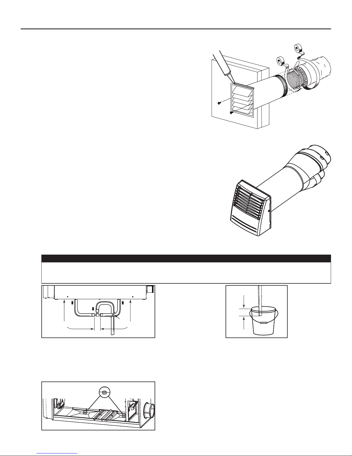
3.7 CONNECTING INSULATED DUCTS TO EXTERIOR PORTS
• For each exterior port, using a jig saw, cut a 5’’ diameter hole in the
exterior wall.
• From the outdoor, slide the exterior port in place and attach it to the
exterior wall, using 2 no. 8 x 1½” provided screws. Seal the outline with
silicone.
• From the inside, pull back the insulation to expose the flexible duct and,
using a tie wrap, attach it to the exterior port rigid duct. Carefully seal
with duct tape. Pull the insulation over the joint. Pull the vapor barrier
over the insulation and over the joint. Apply gently duct tape to the joint
making an airtight seal. See illustration at right.
3.8 INSTALLING TANDEM® TRANSITION* KIT
If desired, it is possible to perform insulated ducts connection with the outdoor
using the Tandem transition kit (purchase separately, part number VTYIK1). The
joist opening needed to install the Tandem transition must be 9¾” minimum. The
maximum height of the Tandem transition is 8¾”. To connect the insulated flexible
ducts to the Tandem transition (Exhaust air to outdoor and Fresh air from outdoor),
follow the instructions included with the kit.
*Patented.
VR0028
3.9 CONNECTING THE DRAIN
A drain tubing (included) must be installed for all HRV units. For ERV units, it is not required, however, it is
recommended for climates where the outdoor temperature typically remains below -13°F, (over a 24-hour
period) for several days in a row, combined with an indoor humidity of 40% or higher.
± 12” ± 12”
VD0311A
Cut two sections of plastic tubing, approximately
12” long, and connect each one to both inner drain
fittings located under the unit as shown.
Join these both sections to the “T” junction and
main tube as shown, to prevent the unit from
drawing unpleasant odors from the drain source.
VD0323
TIE WRAP
VR0003
Tandem transition kit
CAUTION
± 1”
VD0308A
Run the tube to the floor drain or to an alternative
drain pipe or pail.
IMPORTANT
If using a pail to collect water, locate the tube end
approximately 1” from the top of the pail in order to
prevent water from being drawn back up into the unit.
NOTES: 1. For ERV unit, remove both drain plugs inside the unit prior to
install tubing.
2. ERV core and blower assembly removed from illustration to ease
understanding.
11
4. CONTROLS
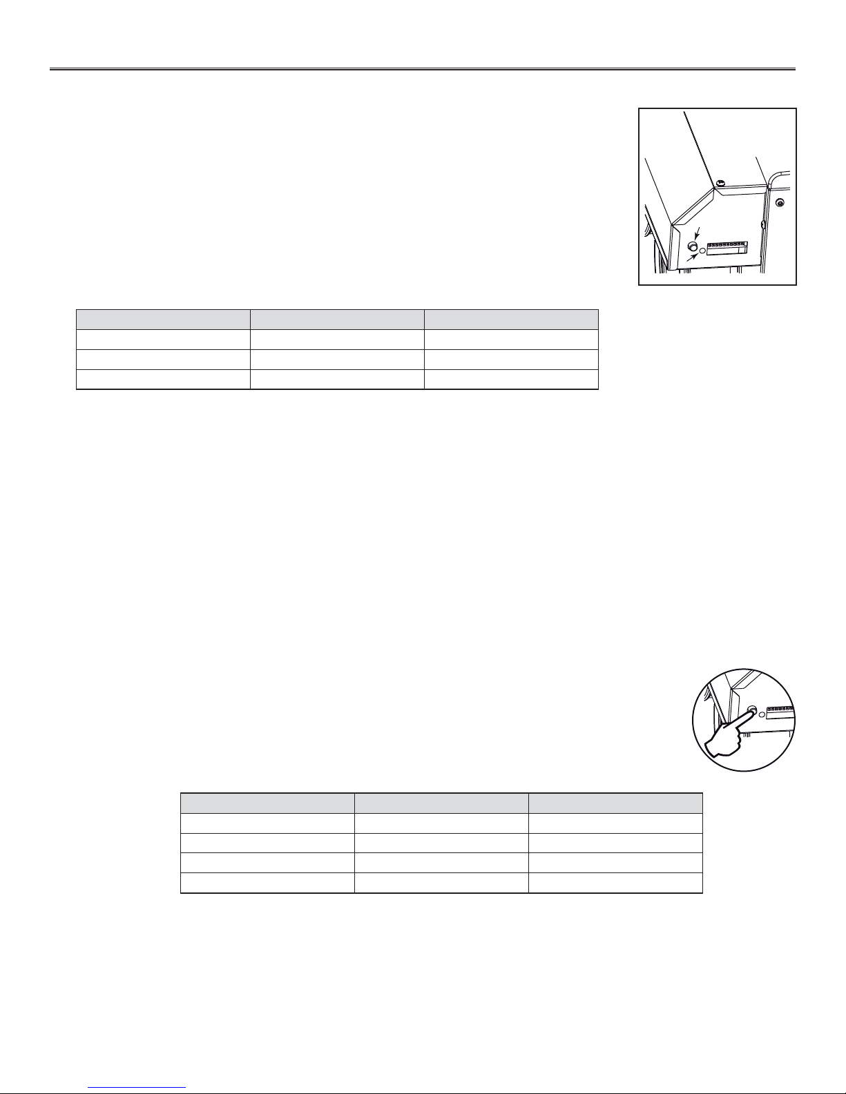
4.1 INTEGRATED CONTROL
These units are equipped with an integrated control located under the electrical compartment of the
unit. Use the push button (1) to control the unit; the LED (2) will then show which mode the unit is in
(see illustration at right).
VD0310
Refer to table below to see how to operate the unit using its integrated control.
PRESS ON PUSH BUTTON LED COLOR RESULTS
ONCE AMBER UNIT IS ON LOW SPEED
TWICE GREEN UNIT IS ON HIGH SPEED
THREE TIMES NO LIGHT UNIT IS OFF
If a problem occurs during the unit operation, its integrated control LED (2) will blink. The color of the blinking light depends on the
type of error detected. Refer to Section 9 Troubleshooting on last pages for further details.
NOTE: The integrated control must be turned OFF to use an optional main control.
1
2
4.2 BOOTING SEQUENCE
The unit booting sequence is similar to a personal computer boot sequence. Each time the unit is plugged after being unplugged, or
after a power failure, the unit will perform a 30-second booting sequence before starting to operate.
During the booting sequence, the integrated defrost control LED will light AMBER for 5 seconds, and then will shut off for 2 seconds.
After that, the LED will light RED for the rest of the booting sequence. During this RED light phase, the unit is checking and resetting
the motorized damper position. Once the motorized damper position completely set, the RED light turns off and the booting sequence
is done.
4.3 SETTING EXTENDED DEFROST
The unit is factory set to normal defrost. In cold region (outdoor temperature -17°F and lower), it may be
necessary to setup extended defrost. During the first 3 seconds of booting sequence, while the integrated
control LED is AMBER, press on push button for about 3 seconds. The LED will blink GREEN the number of times
corresponding to the actual defrost mode of the unit.
NOTE: During setting extended defrost, while the push button is pressed, the LED will light RED to indicate
the signal has been received.
Refer to table below to modify the defrost cycle of the unit. It is possible to change the selection as many times
needed.
DEFROST CYCLE PRESS ON PUSH BUTTON LED BLINKS GREEN
NORMAL (HRV UNIT)ONCE 1 TIME
1
2 EXTENDED (HRV UNIT)TWICE 2 TIMES
3 NORMAL (ERV UNIT)THREE TIMES 3 TIMES
4 EXTENDED (ERV UNIT)FOUR TIMES 4 TIMES
VD0324
To exit setting extended defrost, press 3 seconds on push button OR wait 60 seconds; the LED will blink and shut off, then light RED
(the unit returns in its booting sequence).
12
 Loading...