

Broan ERV140 ECM, ERV160 ECM, HRV160 Installation Manual
INSTALLATION GUIDE
VB0270
MODELS ERV140 ECM*, HRV160 ECM* AND HRV160
HESE UNITS HAVE A SPECIAL BOOTING SEQUENCE, REFER TO PA G E 11.
*T
These products earned the ENERGY STAR® by meeting strict energy efficiency guidelines set by
Natural Resources Canada and the US EPA. They meet ENERGY STAR requirements only when used
in Canada.
! !
RESIDENTIAL INDOOR USE ONLY
READ AND SAVE THESE INSTRUCTIONS
Broan-NuTone LLC; Hartford, Wisconsin www.broan.com 1-800-543-3055
REGISTER YOUR PRODUCT ONLINE AT: www.broan.com/register
For additional information - visit www.broan.com
22636 rev. 04
ABOUT THIS GUIDE
!
Please take note that this guide uses the following symbols to emphasize particular information:
WARNING
Identifies an instruction which, if not followed, might cause serious personal injuries including possibility of death.
CAUTION
Denotes an instruction which, if not followed, may severely damage the unit and/or its components.
ABOUT THESE UNITS
LIMITATION
For residential (domestic) installation only. Installation work and electrical wiring must be done by a qualified person(s) in accordance with
all applicable codes and standards, including fire-rated construction codes and standards.
!
WARNING
TO REDUCE THE RISK OF FIRE, ELECTRIC SHOCK, OR INJURY TO PERSON(S) OBSERVE THE FOLLOWING:
1. Use this unit only in the manner intended by the manufacturer. If you have questions, contact the manufacturer at the address or
telephone number listed in the warranty.
2. We recommend that your unit be inspected by a specialized technician once a year.
3. Before servicing or cleaning the unit, disconnect power cord from electrical outlet.
4. This unit is not designed to provide combustion and/or dilution air for fuel-burning appliances.
5. When cutting or drilling into wall or ceiling, do not damage electrical wiring and other hidden utilities.
6. Do not use the units with any solid-state speed control device other than the corresponding ones listed below:
UNITS MAIN CONTROLS AUXILIARY CONTROLS
ERV140 ECM AND HRV 160 ECM VT8W OR VT7W
HRV160 VT8W, VT7W, VT4W
OR VT6W
59W
AND VB60W
7. This unit must be grounded. The power supply cord has a 3-prong grounding plug for your personal safety. It must be plugged into a
mating 3-prong grounding receptacle, grounded in accordance with the national electrical code and local codes and ordinances. Do
not remove the ground prong. Do not use an extension cord.
8. Do not install in a cooking area or connect directly to any appliances.
9. Do not use to exhaust hazardous or explosive materials and vapors.
10. When performing installation, servicing or cleaning these units, it is recommended to wear safety glasses and gloves.
11. Due to the weight of the unit, two installers are recommended to perform installation.
12. When applicable local regulations comprise more restrictive installation and/or certification requirements, the aforementioned
requirements prevail on those of this document and the installer agrees to conform to these at his own expenses.
CAUTION
1. To avoid prematurate clogged filters, turn OFF the unit during construction or renovation.
2. Please read specification label on product for further information and requirements.
3. Be sure to duct air outside – Do not intake/exhaust air into spaces within walls or ceiling or into attics, crawl spaces, or garage.
4. Intended for residential installation only in accordance with the requirements of NFPA 90B.
5. Do not run any air ducts directly above or closer than 2 ft to any furnace or its supply plenum, boiler, or other heat producing appliance.
If a duct has to be connected to the furnace return plenum, it must be connected not closer than 9’ 10” from this plenum connection to
the furnace. This last distance applies only in regions where the outside temperature falls below 32
6. The ductwork is intended to be installed in compliance with all applicable codes.
7. When leaving the house for a long period of time (more than two weeks), a responsible person should regularly check if the unit
operates adequately.
8. If the ductwork passes through an unconditioned space (e.g.: attic), the ducts must be insulated, and the unit must operate continuously
except when performing maintenance and/or repair. Also, the ambient temperature of the house should never drop below 65°F.
2

TABLE OF CONTENTS
1. T ECHNICAL DATA ..................................................................................................................................4
1.1 AIR DISTRIBUTION ................................................................................................................................... 4
1.2 D
2 INSTALLATION ..................................................................................................................................4-10
2.1 INSPECT THE CONTENT OF THE BOX ........................................................................................................... 4
2.2 U
2.3 L
2.4 P
2.5 C
2.6 I
2.6.1 FULLY DUCTED SYSTEM ...................................................................................................................................6
2.6.2 EXHAUST DUCTED SYSTEM ...............................................................................................................................7
2.6.3 SIMPLIFIED INSTALLATION ..................................................................................................................................8
2.7 CONNECTING THE DUCTS TO THE UNIT ....................................................................................................... 9
2.8 I
2.9 C
3. CONTROLS ....................................................................................................................................11-14
EFROST CYCLES .................................................................................................................................... 4
NIT DOORS .......................................................................................................................................... 4
OCATING THE UNIT ................................................................................................................................. 5
LANNING OF THE DUCTWORK ................................................................................................................... 5
ALCULATING DUCT SIZE ......................................................................................................................... 5
NSTALLING THE DUCTWORK AND REGISTERS ............................................................................................. 6-8
NSTALLING TWO EXTERIOR HOODS ...........................................................................................................10
ONNECTING THE DRAIN .........................................................................................................................10
3.1 UNITS BOOTING SEQUENCE ......................................................................................................................11
3.1.1 ERV140 ECM AND HRV160 ECM .............................................................................................................. 11
3.1.2 HRV160 .................................................................................................................................................... 11
3.2 INTEGRATED CONTROL .............................................................................................................................11
3.3 S
3.4 S
3.5 E
3.5.1 ELECTRICAL CONNECTION TO VT8W MAIN WALL CONTROL ................................................................................. 13
3.5.2 ELECTRICAL CONNECTION TO VT7W MAIN WALL CONTROL ................................................................................. 13
3.5.3 ELECTRICAL CONNECTION TO VT4W MAIN WALL CONTROL ................................................................................. 13
3.5.4 ELECTRICAL CONNECTION TO VT6W MAIN WALL CONTROL ................................................................................. 13
PEED AND DEFROST SETTINGS FOR ERV140 ECM AND HRV160 ECM UNITS ........................................... 12
ETTING EXTENDED DEFROST FOR HRV160 UNIT ...................................................................................... 12
LECTRICAL CONNECTION TO MAIN CONTROL ............................................................................................ 13
3.6 ELECTRICAL CONNECTION TO OPTIONAL AUXILIARY CONTROLS ...................................................................... 14
4. ELECTRICAL CONNECTION TO THE FURNACE/AHU....................................................................................14
5. W
IRING DIAGRAMS ........................................................................................................................ 15-16
ALANCING THE UNIT ..........................................................................................................................17
6. B
6.1 WHAT YOU NEED TO BALANCE THE UNIT .................................................................................................. 17
6.2 P
6.3 B
RELIMINARY STAGES TO BALANCE THE UNIT .............................................................................................. 17
ALANCING PROCEDURE .......................................................................................................................... 17
7. S ERVICE PARTS .................................................................................................................................18
ROUBLESHOOTING ........................................................................................................................19-22
8. T
3
1. TECHNICAL DATA
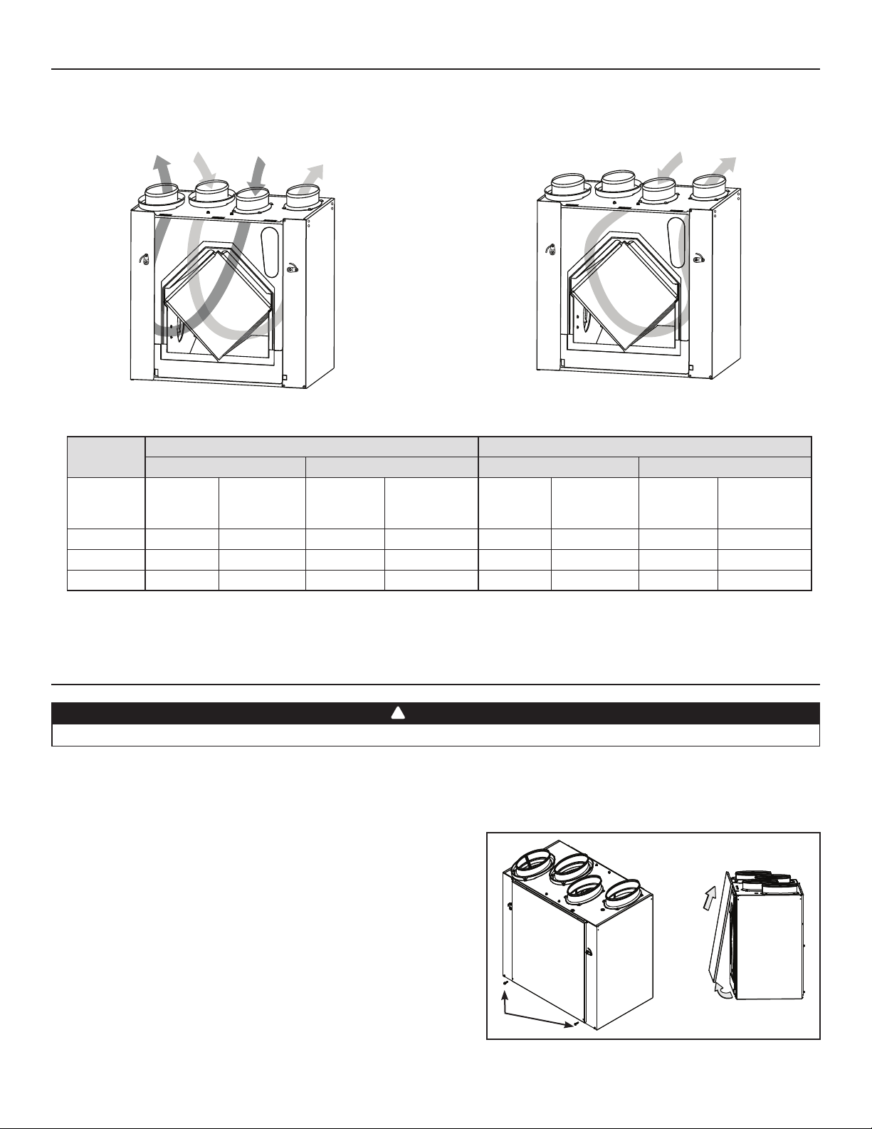
1.1 AIR DISTRIBUTION
NORMAL OPERATION DEFROST OR RECIRCULATION
STALE AIR
TO OUTSIDE
FRESH AIR
FROM OUTSIDE
STALE AIR
FROM
BUILDING
FRESH AIR
BUILDING
TO
STALE AIR
FROM
BUILDING
FILTERED AIR
TO
BUILDING
VF0045
VF0046
1.2 DEFROST CYCLES
OUTDOOR
TEMPERATURE
°F D
NORMAL DEFROST CYCLE (MIN)EXTENDED DEFROST CYCLE (MIN)NORMAL DEFROST CYCLE (MIN)EXTENDED DEFROST CYCLE (MIN)
EFROSTING
23 7 40 9 23 5 40 9 30
5 7 25 9 23 5 25 9 23
-17 10 22 10 22 8 22 10 15
In a cold region, (outside temperature -17°F and lower), it may be necessary to setup EXTENDED DEFROST.
See Section 4.3 or 4.4 according to the unit model.
ERV140 ECM AND HRV160 ECM UNITS HRV160 UNIT
OPERATION
BETWEEN EACH
DEFROST
DEFROSTING
OPERATION
BETWEEN EACH
DEFROST
DEFROSTING
OPERATION
BETWEEN EACH
DEFROST
DEFROSTING
2. INSTALLATION
!
WARNING
When performing installation, it is recommended to wear safety glasses and gloves.
2.1 INSPECT THE CONTENT OF THE BOX
OPERATION
BETWEEN EACH
DEFROST
Inspect the exterior of the unit for shipping damage. Ensure that there is no damage to the door, ports, power cord, etc.
2.2 UNIT DOOR(S)
The ERV140 ECM and HRV160 ECM units have one front door and one
back door while the HRV160 unit has one door. For this last model, the unit
door can be relocated on the back of the unit. This can be helpful to optimize
duct configuration while keeping access for unit maintenance. To change
door location, follow these steps:
A. Remove both door lower mechanical screws no. 8-32 x 1” (1) and set
aside.
B. Open (2) and lift out the door (3).
To remove unit back panel, repeat steps A and B, but instead of removing
2 mechanical screws, there are 4 mechanical screws to be removed. Hang
the door to the back of the unit and secure it by tightening its both lower
mechanical screws. Hang back panel to the front of the unit and secure it by
tightening its four metal screws.
4
A
1
B
3
VO0149
2
2. INSTALLATION (CONT'D)
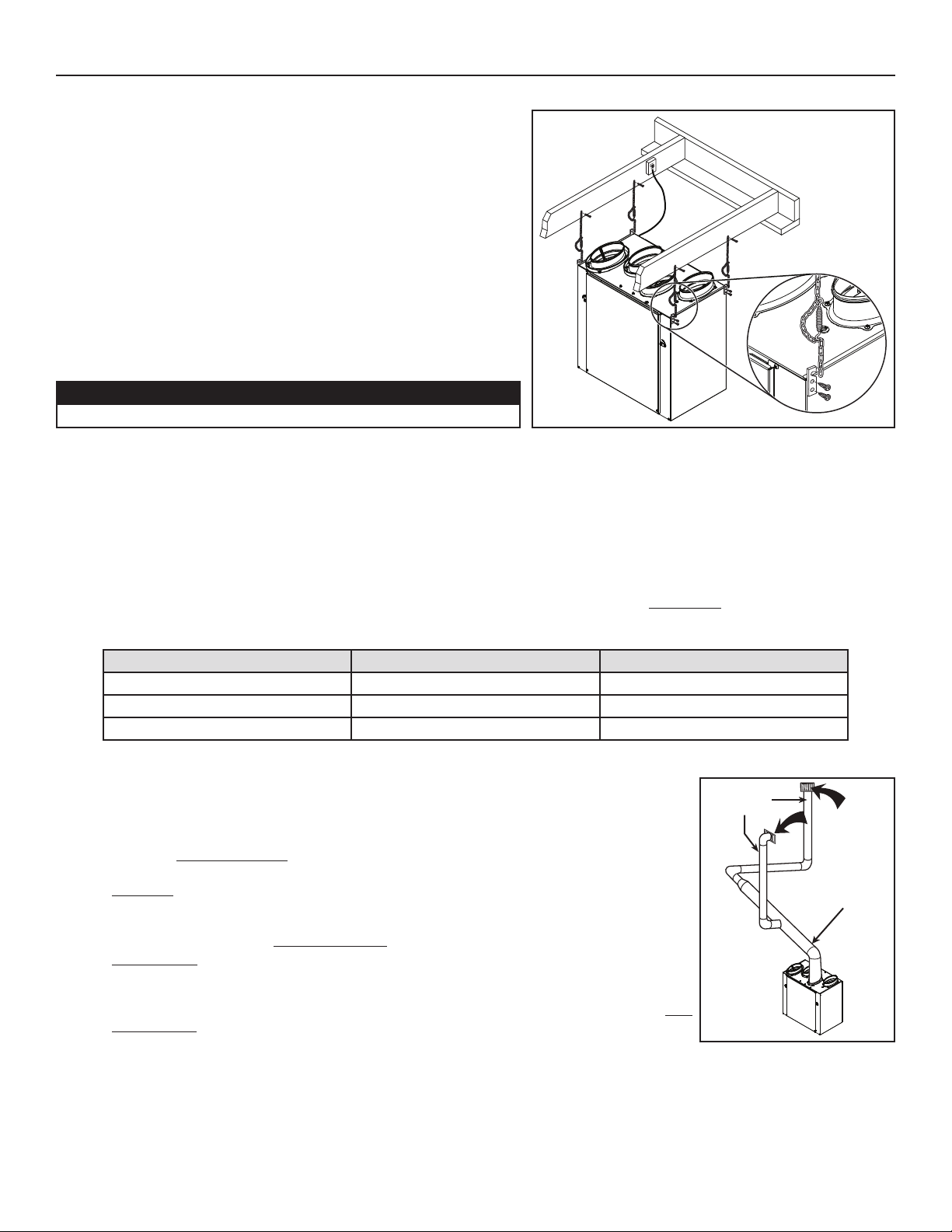
2.3 LOCATING THE UNIT
Choose an appropriate location for the unit.
• Within an area of the house where the ambient temperature is kept
between 50°F and 160°F.
• Away from living areas (dining room, living room, bedroom), if possible.
• So as to provide easy access to the interior of the unit, for semi-annual
and annual maintenance.
• Close to an exterior wall, so as to limit the length of the insulated flexible
duct to and from the unit.
• Away from hot chimneys and other fire hazards.
• Allow for a power source (standard 3-prong grounding outlet).
• Close to a drain. If no drain is close by, use a pail to collect run-off.
Hang the unit with the four chains and springs provided.
See illustration at right.
CAUTION
Make sure the unit is level.
2.4 PLANNING OF THE DUCTWORK
• Keep it simple. Plan for a minimum of bends and joints.
• Keep the length of insulated ducts to a minimum.
• Do not ventilate crawl spaces or cold rooms. Do not attempt to recover the exhaust air from a dryer or a range hood. This would cause
clogging of the filters and recovery module.
• If the house has two floors or more, be sure to plan for at least one exhaust register on the highest lived-in level.
VD0205
2.5 CALCULATING DUCT SIZE
Use the table below to ensure that the ducts you intend to install will be carrying air flows at or under the recommended values.
Avoid installing ducts that will have to carry air flows near the maximum values and never install a duct if its air flow exceeds
the maximum value.
DUCT DIAMETER RECOMMENDED AIR FLOW MAXIMUM AIR FLOW
4” Ø 40 CFM (19 L/S) 60 CFM (28 L/S)
5” Ø 75
6” Ø 120
EXAMPLE OF CALCULATION
Problem: My installation requires two exhaust registers (one for the kitchen, and the other for
the bathroom). I will connect these registers to a main duct which will connect to the unit (high
speed performance value of 140 cfm). What size of duct should I use for the main exhaust duct
and for both end branches leading to the registers? (See illustration at right.)
Solution: Simplified method. (For a more detailed method of calculating duct size, refer to the
ASHRAE or HRAI HANDBOOK.)
Main duct: Table indicates for a 6” Ø duct: recommended air flow: 120 cfm, maximum air flow:
180 cfm. The 140 cfm high speed air flow is close enough to the recommended value (120)
and far away enough from the maximum value (180). Therefore, a 6” Ø duct or larger is an
appropriate choice for the main exhaust duct.
End branches: Each end branch will have to transport a 70 cfm air flow (140 divided by 2). Table
indicates for a 5” Ø duct: recommended air flow: 75 cfm; maximum air flow: 110 cfm. The high
speed air flow of 70 cfm is close enough to the recommended value (75) and far away enough
from the maximum value (110). Therefore, a 5” Ø duct or larger is an appropriate choice for both
end branches.
NOTE: A 4” Ø duct would have been too small because the maximum acceptable value for a
4” Ø duct is 60 cfm.
CFM (35 L/S)110 CFM (52 L/S)
CFM (57 L/S) 180 CFM (85 L/S)
END
BRANCHES
5" Ø,
70 CFM
MAIN BRANCH
6" Ø, 140 CFM
VI0016
5
2. INSTALLATION (CONT'D)
!
2.6 INSTALLING THE DUCTWORK AND REGISTERS
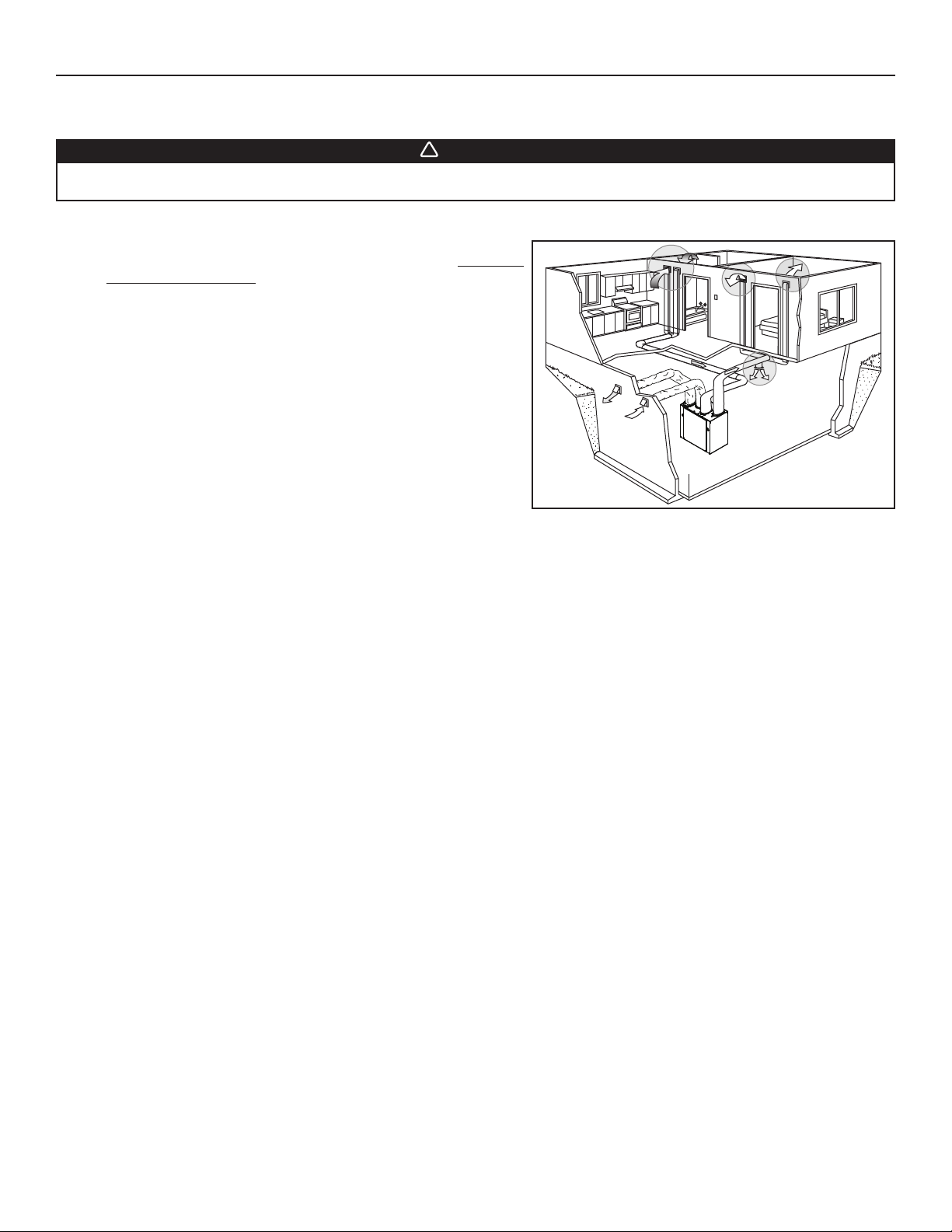
2.6.1 FULLY DUCTED SYSTEM
Stale air exhaust ductwork
Never install a stale air exhaust register in a closed room where a combustion device operates, such as a gas
furnace, a gas water heater or a fireplace.
Stale air exhaust ductwork
• Install the stale air exhaust registers where the contaminants are
produced: kitchen, living room, etc. Position the registers as far from
the stairway as possible and in such a way that the air circulates in
all the lived-in spaces in the house.
• If a register is installed in the kitchen, it must be located at least
4 feet from the range.
• Install the registers 6 to 12 inches from the ceiling on an interior wall
OR install them in the ceiling.
• If possible, measure the velocity of the air flowing through the
registers. If the velocity is higher than 400 ft/min, then the register
type is too small. Replace with a larger one.
Fresh air distribution ductwork
• Install the fresh air distribution registers in bedrooms, dining rooms,
living room and basement.
• Keep in mind that the fresh air registers must be located as far as
possible from the stale air registers.
• Install the registers either in the ceiling or high on the walls with air flow directed towards the ceiling. (The cooler air will then cross
the upper part of the room and mix with room air, before descending to occupant’s level.)
• If a register must be floor installed, direct the airflow up the wall.
WARNING
VH0071
6
!
2. INSTALLATION (CONT'D)
2.6 INSTALLING THE DUCTWORK AND REGISTERS (CONT'D)
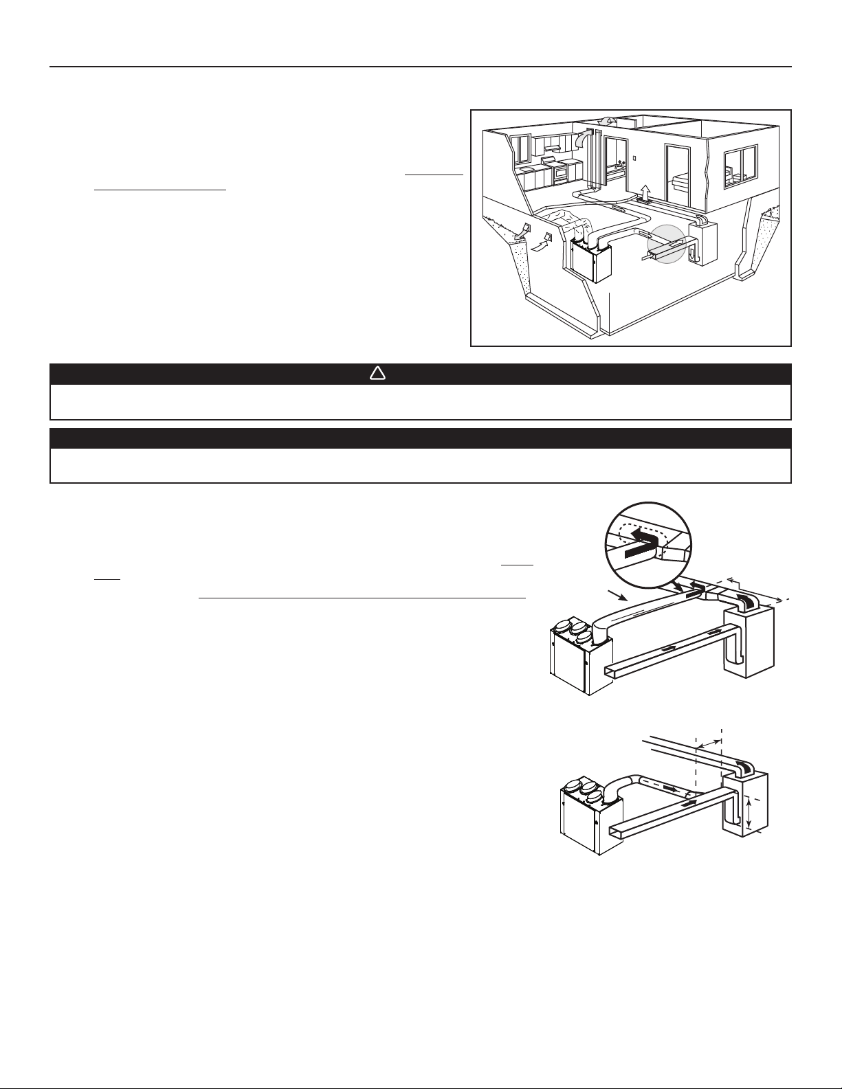
2.6.2 EXHAUST DUCTED SYSTEM
Stale air exhaust ductwork
• Install the stale air exhaust registers where the contaminants are
produced: kitchen, living room, etc. Position the registers as far from
the stairway as possible and in such a way that the air circulates in
all the lived-in spaces in the house.
• If a register is installed in the kitchen, it must be located at least
4 feet from the range.
• Install the registers 6 to 12 inches from the ceiling on an interior wall
OR install them in the ceiling.
• If possible, measure the velocity of the air flowing through the
registers. If the velocity is higher than 400 ft/min, then the register
type is too small. Replace with a larger one.
Fresh air distribution ductwork
VH0072
WARNING
When performing duct connections, always use approved tools and materials. Respect all corresponding laws and
safety regulations. Please refer to your local building code.
CAUTION
When performing duct connections to the furnace/AHU supply duct, this duct must be sized to support the
additional airflow produced by the unit. Also, the use of metal duct is highly recommended.
Method 1: Supply side connection
• Cut an opening into the furnace/air handler supply duct at least 18 inches from the
furnace/air handler.
• Connect this opening to the Fresh air distribution port of the unit (use metal
duct, see figure at right).
• Make sure the unit duct forms an elbow inside the furnace/air handler ductwork.
NOTE: If it is impossible to make an elbow inside the furnace/air handler
supply ductwork, a backdraft damper must be installed to prevent
damages to the ventilation unit.
• If desired, interlock (synchronize) the furnace/air handler blower operation (see
Section 4 ELECTRICAL CONNECTION TO FURNACE/AHU).
Method 2: Return side connection
• Cut an opening into the furnace/air handler return duct not less than 10 feet from the
furnace/air handler (A+B)*.
* This 10-ft. distance applies only in areas where the outside temperature falls below the
freezing point (32°F).
• Connect this opening to the Fresh air distribution port of the unit (see figure at
right).
NOTE: For Method 2, it is not essential that the furnace/air handler runs when the
unit is operation, but we recommend it. If desired, interlock (synchronize)
the furnace/air handler blower operation (see Section 4 ELECTRICAL
CONNECTION TO FURNACE).
METAL DUCT
VJ0061
VJ0062
A+B = NOT LESS
THAN 10’
MINIMUM 18"
A
B
7
2. INSTALLATION (CONT'D)
!
2.6 INSTALLING THE DUCTWORK AND REGISTERS (CONT’D)
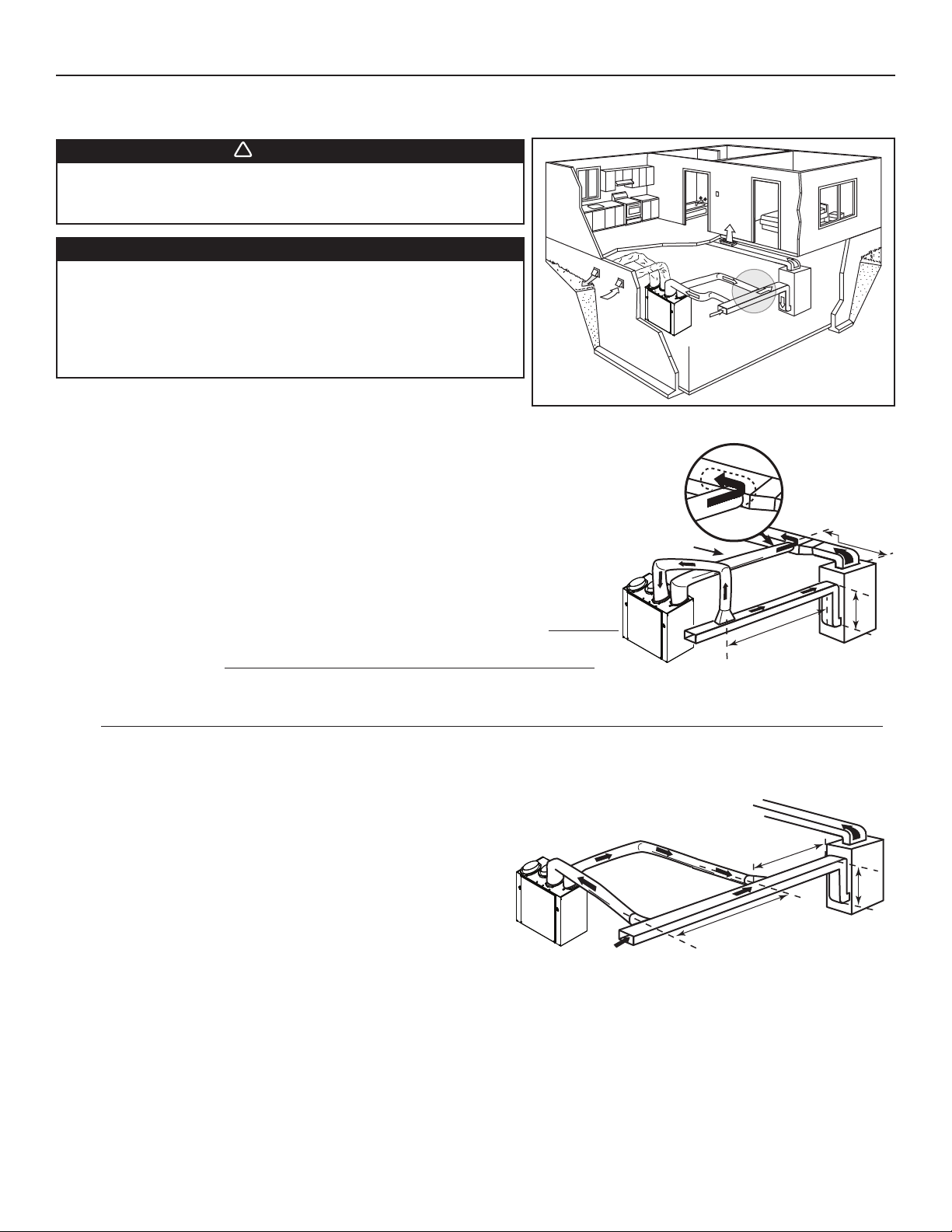
2.6.3 SIMPLIFIED INSTALLATION
WARNING
When performing duct connections, always use approved
tools and materials. Respect all corresponding laws and safety
regulations. Please refer to your local building code.
CAUTION
When performing duct connections to the furnace/AHU supply
duct (Method 1), this duct must be sized to support the
additional airflow produced by the unit. Also, the use of metal
duct is highly recommended. For a Return-Return installation,
the furnace/AHU blower must be in operation when the unit is
in operation. See Section 4.
VH0073
Method 3: Supply-return connection
Stale air intake
• Cut an opening into the furnace/air handler return duct not less than 10 feet from the
furnace/air handler (A+B)*.
* This 10-ft. distance applies only in areas where the outside temperature falls below the
freezing point (32°F).
• Connect this opening to the Exhaust air from building port of the unit.
METAL DUCT
Fresh air distribution
• Cut an opening into the furnace/air handler supply duct at least 18 inches from the
furnace/air handler.
• Connect this opening to the Fresh air distribution port of the unit (use metal duct,
see figure at right).
• Make sure the unit duct forms an elbow inside the furnace/air handler ductwork.
VJ0063
A
A+B = NOT LESS
THAN 10’
NOTE: If it is impossible to make an elbow inside the furnace/air handler supply ductwork, a backdraft damper must be installed
to prevent damages to the ventilation unit.
NOTE: For Method 3, it is not essential to synchronize the furnace/AHU blower operation with the unit operation, but we recommend it.
M
INIMUM 18"
B
Method 4: Return-return connection
Stale air intake
• Cut an opening into the furnace/air handler return duct at least
3feet ahead of the fresh air distribution duct connection.
• Connect this opening to the Exhaust air from building port of the
unit.
A
B
Fresh air distribution
• Cut an opening into the furnace/air handler return duct not less
than 10 feet from the furnace/air handler (A+B)*.
MINIMUM 3'
VJ0064
A+B = NOT LESS
THAN 10’
* This 10-ft. distance applies only in areas where the outside temperature
falls below the freezing point (32°F).
• Connect this opening to the Fresh air distribution port of the unit.
8
2. INSTALLATION (CONT'D)
2.7 CONNECTING THE DUCTS TO THE UNIT
NOTE: All unit ports are were created to be connected to ducts having a minimum of 6” diameter, but if need be, they can be connected
to bigger sized ducts by using an appropriate transition (e.g.: 6” diameter to 7” diameter transition).
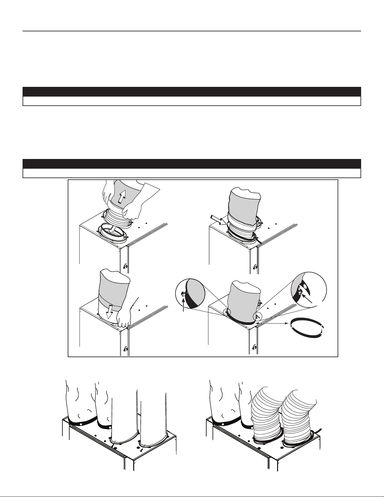
Insulated flexible ducts
Use the following procedure to connect the insulated flexible ducts to the ports of the unit (Exhaust air to outside and Fresh air from
outside ports).
CAUTION
If ducts have to go through an unconditioned space (e.g.: attic), always use insulated ducts.
1. Pull back the insulation to expose the flexible duct.
2. Attach the flexible duct to the port using tie wrap.
3. Pull the insulation over the joint and tuck in between the inner and outer rings of the double collar.
4. Pull down the vapor barrier (shaded part in illustrations below) over the outer ring to cover it completely. Fasten in place the vapor
barrier using the port strap (included in unit parts bag). To do so, insert one collar pin through vapor barrier and first strap hole,
then insert the other collar pin through vapor barrier and center strap hole and close the loop by inserting the first collar pin in the
last strap hole.
CAUTION
Make sure the vapor barrier on the insulated ducts does not tear during installation to avoid condensation within the ducts.
COLLAR PIN
VJ0067
Non-insulated rigid ducts
Use metal screws and duct tape to connect the rigid ducts to the
unit ports.
VJ0066
COLLAR PIN
Non-insulated flexible ducts
Use tie wraps to connect the flexible ducts to the unit ports.
9
2. INSTALLATION (CONT'D)
!
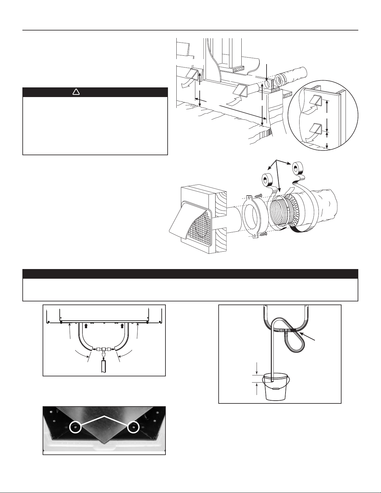
2.8 INSTALLING TWO EXTERIOR HOODS
Choose an appropriate location to install the exterior hoods:
• There must be a minimum distance of 6 feet between
the hoods to avoid cross-contamination
• There must be a minimum distance of 18 inches
from the ground
WARNING
Make sure the intake hood is at least 6 feet
away from any of the following:
• Dryer exhaust, high efficiency furnace vent,
central vacuum vent
• Gas meter exhaust, gas barbecue-grill
• Any exhaust from a combustion source
• Garbage bin and any other source of contamination
Refer to figure at right for connecting insulated ducts to the
exterior hoods. An “Anti-gust intake hood’’ should be installed
in regions where a lot of snow is expected to fall.
EXHAUST HOOD
18"
6'
INTAKE HOOD
6" Ø
18"
TAPE AND DUCT TIE
PTIONAL DUCT
O
LOCATION
6'
18"
VD0028
2.9 CONNECTING THE DRAIN
CAUTION
A drain tubing (included) must be installed for model HRV160TE and HRV160T. For model ERV140TE, it is not required,
however, it is recommended for climates where the outside temperature typically remains below -13°F, (over a
24-hour period) for several days in a row, combined with an indoor humidity of 40% or higher.
16" 16"
VO0275
Cut 2 sections of the plastic tube, at least 16” long, and attach them
to each inner drain fitting, located under the unit.
Join both short sections to the “T” junction and main tube as shown.
DRAIN PLUGS
VD0239
NOTE: For model ERV140 ECM, remove both drain plugs inside
the unit prior to install tubing.
± 1”
VD0232A
Make a water trap loop in the tube to prevent the unit from
drawing unpleasant odors from the drain source. Make sure this
loop is located OVER the “T” as shown. Run the tube to the floor
drain or to an alternative drain pipe or pail.
IMPORTANT
If using a pail to collect water, locate the tube end approximately
1” from the top of the pail in order to prevent water from being
drawn back up into the unit.
10
TIE WRAP
3. CONTROLS
All units are equipped with an integrated control located under the unit, on the recessed side of electrical compartment. Plug the unit.
3.1 UNITS BOOTING SEQUENCE
The unit booting sequence is similar to a personnal computer boot sequence. Each time the unit is plugged after being unplugged, or after
a power failure, the unit will perform a 30-second booting sequence before starting to operate.
3.1.1 ERV140 ECM and HRV160 ECM
During the booting sequence, the integrated control LED will light AMBER for 10 seconds. After that, the LED will light RED
for the rest of the booting sequence. During this RED light phase, the unit is checking and resetting the motorized damper
position. Once the motorized damper position completely set, the RED light turns off and the booting sequence is done.
NOTE: No command will be taken until the unit is fully booted.
3.1.2 HRV160
During the booting sequence, the integrated control LED will light GREEN (unit set in normal defrost) or amber (unit set in
extended defrost) for 3 seconds, and then will shut off for 2 seconds. After that, the LED will light RED for the rest of the booting
sequence. During this RED light phase, the unit is checking and resetting the motorized damper position. Once the motorized
damper position completely set, the RED light turns off and the booting sequence is done.
NOTE: No command will be taken until the unit is fully booted.
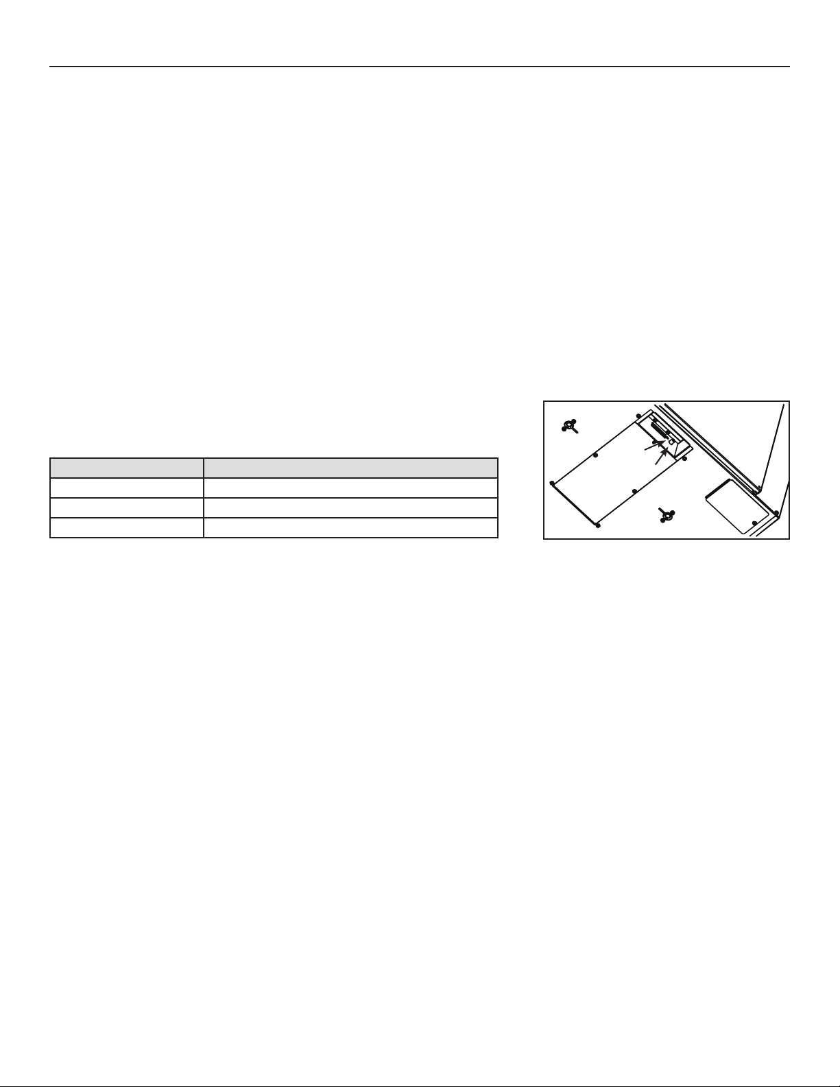
3.2 INTEGRATED CONTROL
Use the push button (1) to control the unit. The LED (2) will then show on which mode the
unit is in.
Refer to table below to see how to operate the unit using its integrated control.
LED COLOR RESULTS
AMBER UNIT IS ON LOW SPEED
GREEN UNIT IS ON HIGH SPEED
NO LIGHT UNIT IS OFF OR CONTROLLED BY A MAIN WALL CONTROL
If a problem occurs during the unit operation, its integrated control LED (2) will blink. The color of the blinking light depends on the type
of error detected. Refer to Section 9 Troubleshooting on page 20 for further details.
NOTE: When using main control, the integrated control must be turned off.
VD0206
2
1
BOTTOM OF THE UNIT
11

3. CONTROLS (CONT’D)
3.3 SPEED AND DEFROST SETTINGS FOR ERV140 ECM AND HRV160 ECM UNITS
The special design of ERV140 ECM and HRV160 ECM units offers 5 speed ranges to better meet to different ventilation needs.
Refer to the table below to choose the right speed range according to the size of the house:
SPEED RANGE HRV MIN. SPEED HRV MAX. SPEED ERV MIN. SPEED ERV MAX. SPEED
NOTE: These CFM values are
approximate, they may vary
according to the installation
static pressure.
These units are factory set to normal defrost. In cold region (outside
temperature -17°F and lower), it may be necessary to setup extended defrost.
TO MODIFY THE FACTORY SETTINGS, PROCEED AS FOLLOW:
NOTE: Anytime in setting process, if there is no activation on push button for 60 seconds, the unit will automatically exit setting mode, but
the settings made before this 60-second delay will remain.
ACTION
During the first 7 seconds of booting sequence, while the
integrated control LED is AMBER, press on push button for about
3 seconds.
Set the speed range by presssing consecutively on push button
the number of times corresponding to the desired speed range.
See table below.
1 85 CFM 157 CFM 85 CFM 140 CFM
2 65 CFM 157 CFM 65 CFM 140 CFM
ACTORY SET) 55 CFM 125 CFM 55 CFM 125 CFM
3 (F
4 40 CFM 125 CFM 40 CFM 125 CFM
5 40 CFM 80 CFM 40 CFM 80 CFM
DEFROST TABLE DEFROST CYCLE
1 FACTORY SET (HRV UNITS) NORMAL (HRV UNITS)
2E
ACTORY SET (ERV UNITS) NORMAL (ERV UNITS)
3 F
4E
XTENDED (HRV UNITS)
XTENDED (ERV UNITS)
RESULT
The LED will blink RED one time every 3 seconds to indicate the
integrated control is in CFM setup mode (HIGH speed).
Every 3 seconds, the LED will blink RED the number of times
corresponding to the chosen speed range.
See table below.
SPEED RANGE PRESS ON PUSH BUTTON LED BLINKS RED
1O
NCE 1 TIME
2TWICE 2 TIMES
NOTE: It is possible to change the selection as many
times needed.
3THREE TIMES 3 TIMES
4FOUR TIMES 4 TIMES
5FIVE TIMES 5 TIMES
Press on push button for about 3 seconds to access setting
defrost mode.
Press on push button twice to set the unit in extended defrost
mode.
The LED will blink GREEN one time every 3 seconds to indicate
the unit is set in normal defrost mode.
The LED will blink GREEN twice every 3 seconds to indicate the
unit is in extended defrost mode.
DEFROST TABLE PRESS ON PUSH BUTTON LED BLINKS GREEN
NORMAL (HRV UNITS)ONCE 1 TIME
1
NOTE: It is possible to change the selection as many
times needed.
2 EXTENDED (HRV UNITS)TWICE 2 TIMES
3 NORMAL (ERV UNIT)THREE TIMES 3 TIMES
4 EXTENDED (ERV UNIT)FOUR TIMES 4 TIMES
Wait 60 seconds OR press 3 seconds on push button to exit
setting mode.
The LED will blink and shut off, then light RED (the unit returns
in its booting sequence).
3.4 SETTING EXTENDED DEFROST FOR HRV160 UNIT
This unit is factory set to normal defrost. In cold regions (outdoor temperature -17°F and lower), it may be necessary to setup
extended defrost. During the first 2 seconds of booting sequence, while the integrated control LED is GREEN, press on push button for
3 seconds to set the unit in extended defrost; the LED will blink AMBER to show the unit is in extended defrost mode. After that, the LED
will shut off, then light RED (the unit returns in its booting sequence).
12
3. CONTROLS (CONT’D)
!
3.5 ELECTRICAL CONNECTION TO MAIN CONTROL
For more convenience, these units can also be controlled using an optional main wall control.
NOTES: 1. The integrated control must be turned OFF to use an optional main control.
2. If an optional auxiliary control is used, if activated, this auxiliary control will override the optional main control.
WARNING
Always disconnect the unit before making any connections. Failure in disconnecting power could result in
electrical shock or damage of the wall control or electronic module inside the unit.
CAUTION
Never install more than one optional main wall control per unit. Make sure that the wires do not short-circuit
between themselves or by touching any other components on the wall control. Avoid poor wiring connections. To
reduce electrical interference (noise) potential, do not run wall control wiring next to control contactors or near
light dimming circuits, electrical motors, dwelling/building power or lighting wiring, or power distribution panel.
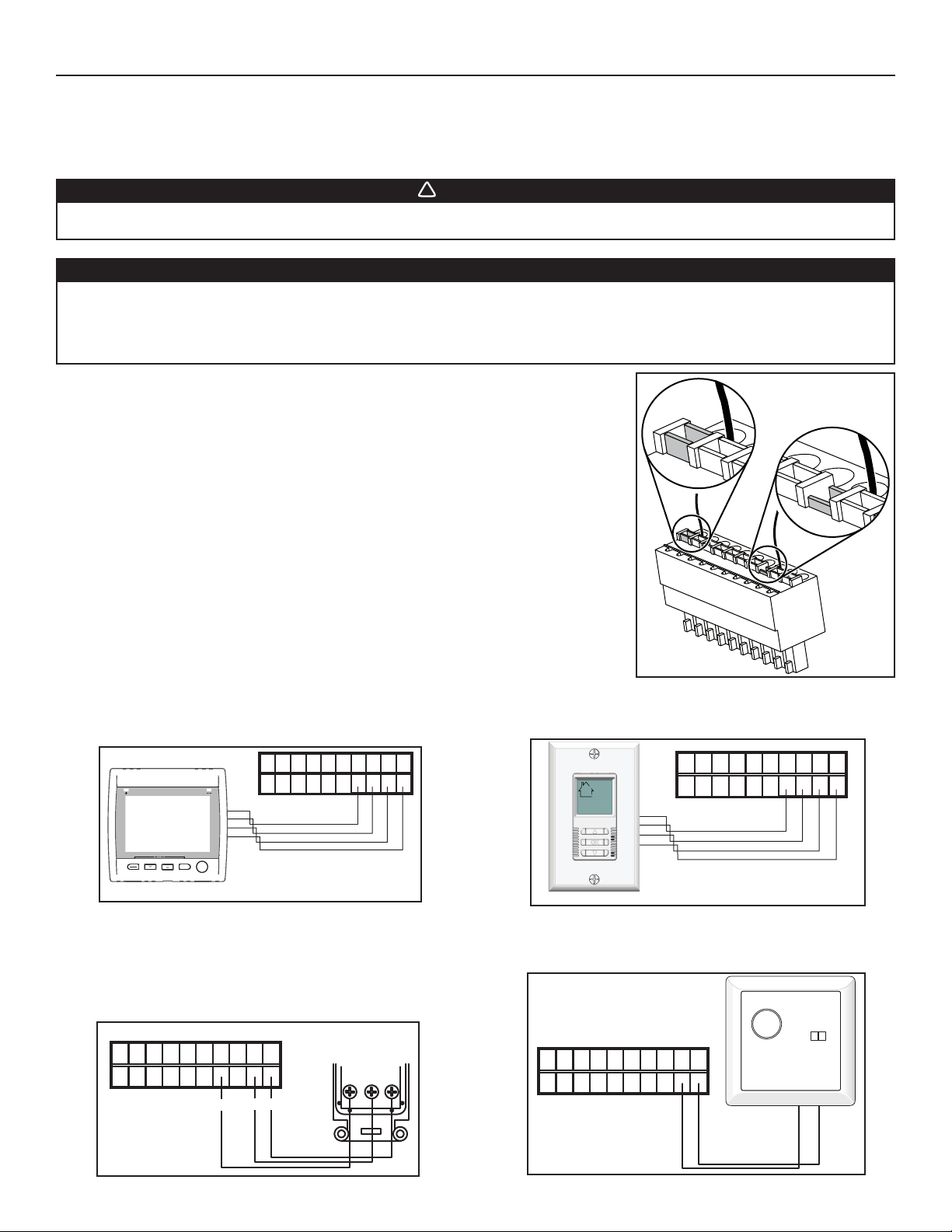
B
A
Use the terminal connector included in the installation kit to perform the electrical connection for
main and optional wall controls. Check if all wires are correctly inserted in their corresponding
holes in the terminal block. (A wire is correctly inserted when its orange receptacle is lower
than another one without wire. On picture at right, wire A is correctly inserted, but wire B is
not.)
3.5.1 ELECTRICAL CONNECTION TO VT8W MAIN W ALL CONTROL
(ERV140 ECM AND HRV160 ECM UNITS ONLY)
NO C NC I OC OL Y R G B
VE0181
MODE
PREF
SET
SMART
3.5.3 ELECTRICAL CONNECTION TO VT4W
MAIN WALL CONTROL (HRV160 UNIT ONLY)
MAIN WALL CONTROL
NO C NC I OC OL Y R G B
G
Y
B
VT4W
REAR VIEW
Y
BG
VE0272
3.5.2 ELECTRICAL CONNECTION TO VT7W MAIN WALL CONTROL
(ALL UNITS)
NO C NC I OC OL Y R G B
VE0250
3.5.4 ELECTRICAL CONNECTION TO VT6W (HRV160 UNIT ONLY)
NO C NC I OC OL Y R G B
VE0328A
VE0187
13
3. CONTROLS (CONT’D)
!
3.6 ELECTRICAL CONNECTION TO OPTIONAL AUXILIARY CONTROLS (ALL UNITS)
NO C NC I OC OL Y R G B
VE0371
Once the control(s) connections have been made, insert the terminal
connector on the recessed side of electrical compartment.
NOTE: For information about the operation of the wall controls, refer to the
user guide.
VD0206
59W
TERMINAL
CONNECTOR
BOTTOM OF THE UNIT
VB60W
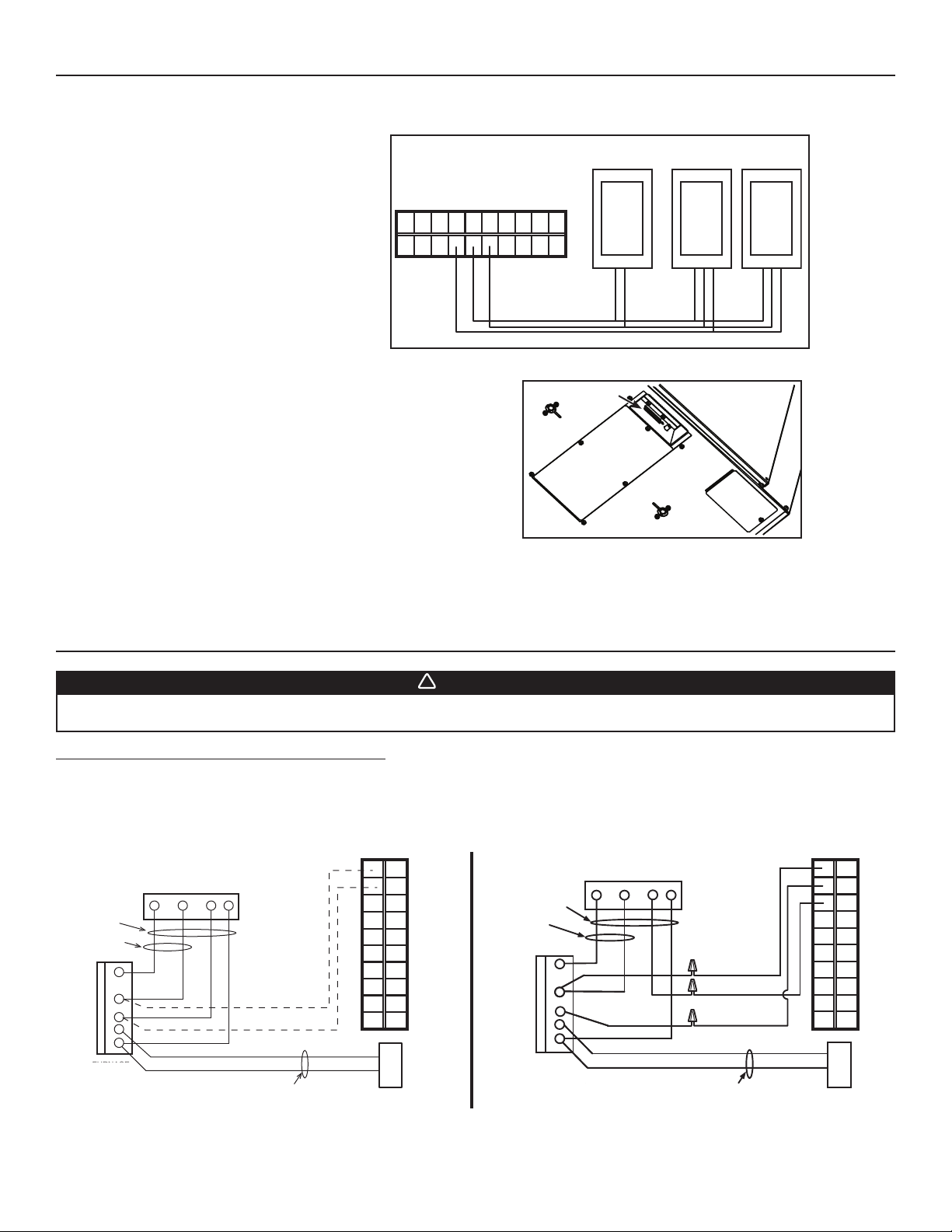
4. ELECTRICAL CONNECTION TO THE FURNACE/AHU
WARNING
Never connect a 120-volt AC circuit to the terminals of the furnace/AHU interlock (standard wiring). Only use the
low voltage class 2 circuit of the furnace/AHU blower control.
For a furnace/AHU connected to a cooling system:
On some older thermostats, energizing the “R” and “G” terminals at the furnace/AHU has the effect of energizing “Y” at the thermostat and
thereby turning on the cooling system. If you identify this type of thermostat, you must use the ALTERNATE FURNACE/AHU INTERLOCK WIRING.
STANDARD FURNACE/AHU INTERLOCK WIRING ALTERNATE FURNACE/AHU INTERLOCK WIRING
NO C NC I OC OL Y R G B
UNIT TERMINAL CONNECTOR
COOLING SYSTEM
FOUR
WIRES
TWO WIRES
heating only
W
R
G
C
Y
FURNACE
FURNACE/AHU
24-VOLT
24-VOLT
TERMINAL BLOCK
BLOCK
TERMINAL
VE0108A
W R G
THERMOSTAT
Y
TERMINALS
TWO WIRES
NO C NC I OC OL Y R G B
COOLING SYSTEM
UNIT TERMINAL CONNECTOR
4 WIRES
2 WIRES
heating only
W
R
G
C
Y
FURNACE
FURNACE/AHU
24-VOLT
24-VOLT
TERMINAL BLOCK
BLOCK
TERMINAL
W R G Y
R
Y
THERMOSTAT
TERMINAL
wiring
nuts
NO
NC
C
2 WIRES
14
 Loading...