

Page 1
E12000 Series
ENGLISH......................................2
FRANÇAIS.................................12
ESPAÑOL...................................22
In USA - Broan-NuTone LLC; 926 W. State Street, Hartford, Wisconsin 53027
In Canada - Broan-NuTone Canada Inc.; 1140 Tristar Drive, Mississauga, ON L5T 1H9
REGISTER YOUR PRODUCT ONLINE AT : www.Broan.com/register
For additional Information visit www.Broan.com
Page 2
READ AND SAVE THESE INSTRUCTIONS
!
INTENDED FOR DOMESTIC COOKING ONLY
!
WARNING
TO REDUCE THE RISK OF FIRE, ELECTRIC SHOCK, OR INJURY TO PERSONS,
OBSERVE THE FOLLOWING:
1. Use this unit only in the manner intended by the manufacturer. If you have questions,
contact the manufacturer at the address or telephone number listed in the warranty.
2. Before servicing or cleaning unit, switch power off at service panel and lock service
panel to prevent power from being switched on accidentally. When the service
disconnecting means cannot be locked, securely fasten a prominent warning device,
such as a tag, to the service panel.
3. Installation work and electrical wiring must be done by a qualified person(s) in accordance with all applicable codes and standards, including fire-rated construction codes
and standards.
4. Sufficient air is needed for proper combustion and exhausting of gases through the flue
(chimney) of fuel burning equipment to prevent backdrafting. Follow the heating equipment manufacturer’s guidelines and safety standards such as those published by the
National Fire Protection Association (NFPA), and the American Society for Heating,
Refrigeration and Air Conditioning Engineers (ASHRAE), and the local code authorities.
5. When cutting or drilling into wall or ceiling, do not damage electrical wiring and other
hidden utilities.
6. Ducted fans must always be vented to the outdoors.
7. Do not use this unit with any separate solid-state speed control device.
8. To reduce the risk of fire, use only metal ductwork.
9. This unit must be grounded.
10. When applicable local regulations comprise more restrictive installation and/or
certification requirements, the aforementioned requirements prevail on those of this
document and the installer agrees to conform to these at his own expenses.
TO REDUCE THE RISK OF A RANGE TOP GREASE FIRE:
A. Never leave surface units unattended at high settings. Boilovers cause smoking and
greasy spillovers that may ignite. Heat oils slowly on low or medium settings.
B. Always turn hood ON when cooking at high heat or when cooking flambeing foods. (i.e.
Crêpes Suzette, Cherries Jubilee, Peppercorn Beef Flambé).
C. Clean ventilating fans frequently. Grease should not be allowed to accumulate on fan or
filter.
D. Use proper pan size. Always use cookware appropriate for the size of the surface
element.
WARNING
TO REDUCE THE RISK OF INJURY TO PERSONS IN THE EVENT OF A RANGE TOP
GREASE FIRE, OBSERVE THE FOLLOWING:*
1. SMOTHER FLAMES with a close-fitting lid, cookie sheet, or metal tray, then turn off the
burner. BE CAREFUL TO PREVENT BURNS. IF THE FLAMES DO NOT GO OUT
IMMEDIATELY, EVACUATE AND CALL THE FIRE DEPARTMENT.
2. NEVER PICK UP A FLAMING PAN - You may be burned.
3. DO NOT USE WATER, including wet dishcloths or towels - This could cause a violent
steam explosion.
4. Use an extinguisher ONLY if:
A. You own a Class ABC extinguisher and you know how to operate it.
B. The fire is small and contained in the area where it started.
C. The fire department has been called.
D. You can fight the fire with your back to an exit.
* Based on “Kitchen Fire Safety Tips” published by NFPA.
- 2 -
Page 3

!
CAUTION
1. For indoor use only.
2. To reduce risk of fire and to properly exhaust air, be sure to duct air outside. Do not vent
exhaust air into spaces within walls or ceilings or into attics, crawl spaces, or garages.
3. Take care when using cleaning agents or detergents.
4. Avoid using food products that produce flames under the Range Hood.
5. For general ventilating use only. Do not use to exhaust hazardous or explosive mate-
rials and vapors.
6. To avoid motor bearing damage and noisy and/or unbalanced impellers, keep drywall
spray, construction dust, etc. off power unit.
7. Your hood motor has a thermal overload which will automatically shut off the motor if it
becomes overheated. The motor will restart when it cools down. If the motor continues
to shut off and restart, have the hood serviced.
8. For best capture of cooking impurities, the bottom of the hood should be a minimum of
24" and a maximum of 30" above the cooking surface.
9. Two installers are recommended because of the large size and weight of this hood.
10. Please read specification label on product for further information and requirements.
11. Automatically operated device. To reduce the risk of injury, disconnect power before
servicing.
12. Do not operate any fan with a damaged cord or plug. Discard fan or return to an authorized
service facility for examination and/or repair.
- 3 -
Page 4
PREPARE THE HOOD
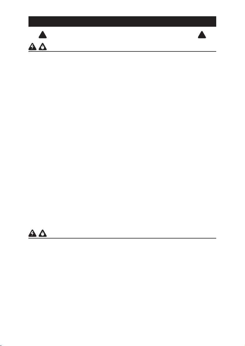
Unpack hood and check contents.
You should receive:
1 - Hood
1 - Parts Bag (B080810359) containing:
3 - Mounting Screws (3.9 x 6 mm Flat Head)
1 - Parts Bag (B080810871) containing:
1 - Right Bracket
1 - Left Bracket
2 - Mounting Screws (M4 x 8 mm)
2 - Washers
4 - Mounting Screws (3.9 x 9.5 mm)
4 - Mounting Screws (4.2 x 15 mm)
4 - Mounting Screws (4.2 x 32 mm)
1 - Discharge Collar
1 - Spacing Bar
1 - Installation Instructions
DISCHARGE
COLLAR
LEFT
BRACKET
RIGHT
BRACKET
2 WASHERS
SPACING BAR
2 MOUNTING SCREWS (M4 x 8 mm)
4 MOUNTING SCREWS (4.2 x 15 mm)
4 MOUNTING SCREWS (4.2 x 32 mm)
3 MOUNTING SCREWS (3.9 x 6 mm)
4 MOUNTING SCREWS (3.9 x 9.5 mm)
- 4 -
Page 5
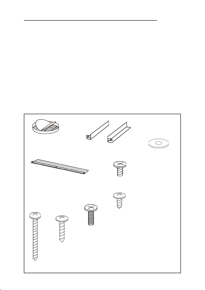
INSTALL THE DUCTWORK
(DUCTED HOODS ONLY)
NOTE: To reduce the risk of fire, use only
metal ductwork.
1. Decide where the ductwork will run
between the hood and the outside.
2. A straight, short duct run will allow the hood
to perform most efficiently.
3. Long duct runs, elbows, and transitions
will reduce the performance of the hood.
Use as few of them as possible. Larger
ducting may be required for best performance
with longer duct runs.
4. Install a roof or wall cap. Connect round
metal ductwork to cap and work back
towards hood location. Use duct tape to
seal the joints between ductwork sections.
FIGURE 1
ROOF CAP
HOOD
24” TO 30” ABOVE
COOKING SURFACE
6”
ROUND DUCT
WALL
CAP
ROUND
ELBOW
SPACING BAR INSTALLATION
To compensate possible depth voids between
the appliance and the wall, a plastic SPACING
BAR to be fixed at the back of the appliance
by means of the three screws (3.9 x 6 mm) is
included. The 3 screws to be used are
contained in the accessory bag attached to
the plastic spacing bar.
Cut the spacing bar according to the distance
to be adjusted.
FIGURE 2
MOUNTING SCREWS
(3.9 x 6 mm)
- 5 -
Page 6
WIRING
Note: This range hood must be properly
grounded. The unit should be installed by a
qualified electrician in accordance with all
applicable national and local electrical
codes.
GROUNDING INSTRUCTIONS
This appliance must be grounded. In the event
of an electrical short circuit, grounding
reduces the risk of electric shock by providing
an escape wire for the electric current.
This appliance is equipped with a cord having
a grounding wire with a grounding plug.
The plug must be plugged into an outlet that
is properly installed and grounded.
WARNING - Improper grounding can result in a risk of electric shock.
Consult a qualified electrician if the grounding instructions are not completely
understood, or if doubt exists as to whether the appliance is properly grounded.
Do not use an extension cord. If the power supply cord is too short, have a qualified
electrician install an outlet near the appliance.
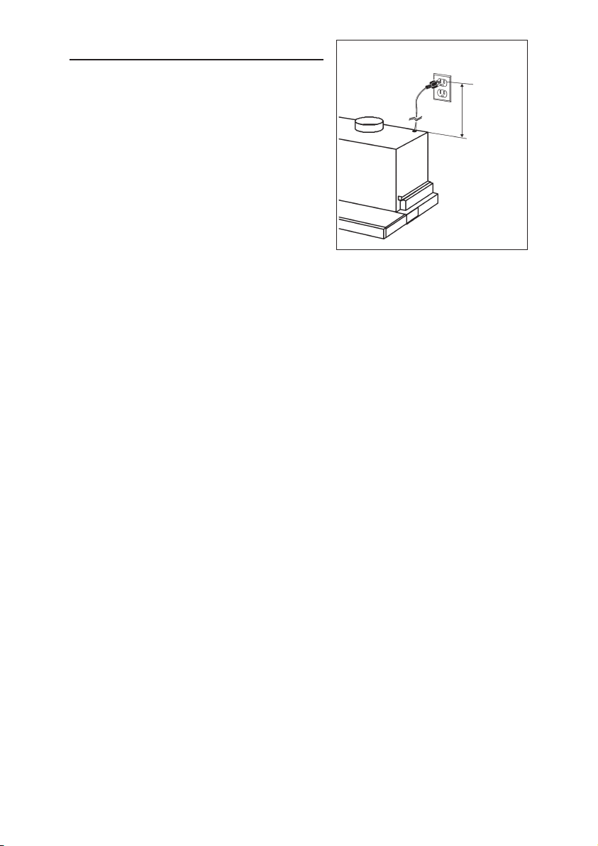
Position the power outlet at a maximum distance of 33-7/16” (85 cm) from where
the lead exits from the hood (see Figure 3).
FIGURE 3
33-7/16”
MAX
- 6 -
Page 7
INSTALLATION
The hood must be installed inside a
cabinet.
ATTENTION: 2 persons are required
for proper installation; the unit should
be installed by a qualified operator.
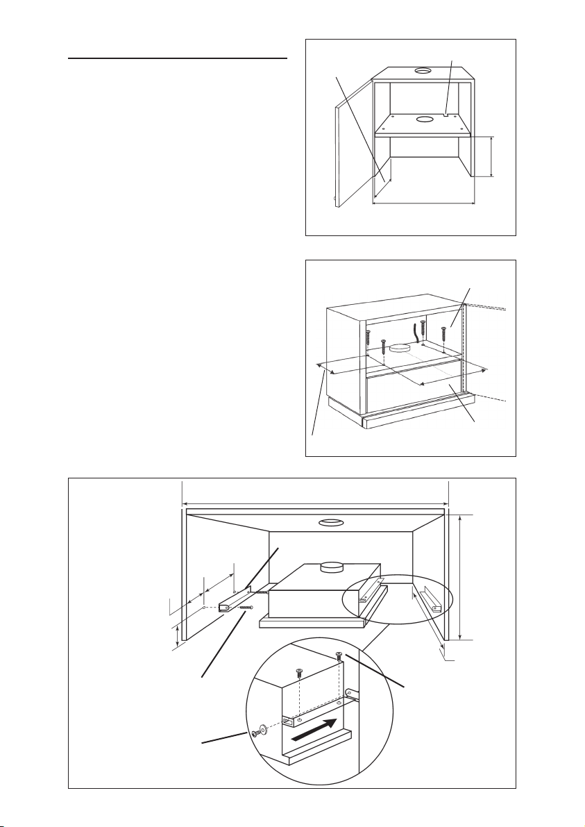
For the cabinet measurements, refer to
Figure 4.
Installation directly to cabinet
Refer to Figure 5.
1. Make the 4 necessary mounting holes
in the cabinet and cut the air venting
and power cord holes.
2. Move the hood close to the bottom of
the cabinet and then secure the unit
by means of the 4 self-tapping screws
(4.2 x 32 mm) supplied.
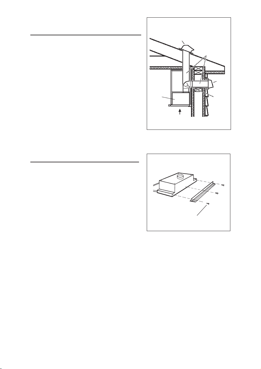
Installation to the cabinet with
brackets
Refer to Figure 6.
1. Take the two brackets out of the
accessory bag together with the 4
screws provided (4.2 x 15 mm).
2. Fit the brackets (S) to the cabinet
being careful to position these
correctly.
3. Adjust the angle of the hood with
the 4 leveling screws (3.9 x 9.5 mm)
4. Fasten the hood to the brackets
using the 2 screws (M4 x 8 mm)
and 2 washers.
FIGURE 4
12-3/16”
FIGURE 5
8-9/16”
1-3/4” x 1-3/4”
24”
30”
MOUNTING SCREWS
(4.2 x 32 mm)
18-1/8” (24”)
24-1/8” (30”)
10-1/4”
FIGURE 6
2-3/16”
3-1/8”
MOUNTING SCREWS
(4.2
MOUNTING SCREWS
X 8 MM)
(M4
X 15 MM)
7-1/2”
24” - 30”
S
- 7 -
12”
MIN.
12-3/16”
LEVELING SCREWS
X 9.5 MM)
(3.9
Page 8
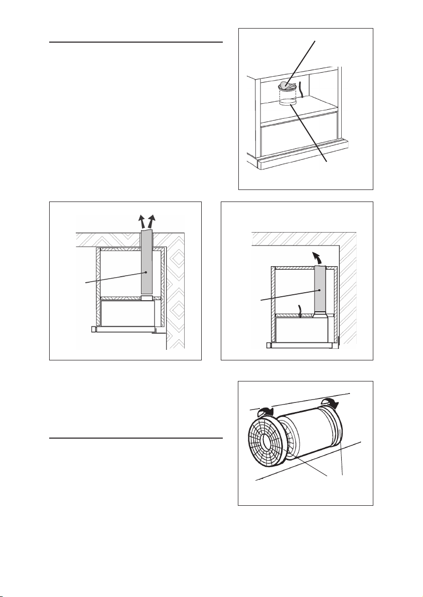
CONNECT DUCTWORK
(DUCTED HOODS ONLY)
1. Install the discharge collar into the duct
connector of the range hood. Fig. 7
2. Use 6" round metal duct to connect the
discharge collar on the hood to the
ductwork above. See Fig. 8
3. Use duct tape to make all joints secure
and air tight.
4. Insert the unit plug into the power outlet.
FIGURE 7
DISCHARGE
COLLAR
DUCT
CONNECTOR
FIGURE 8
Ø 6”
ROUND
METAL
DUCT
NON-DUCTED
RECIRCULATION FILTER
INSTALLATION
(NON-DUCTED HOODS ONLY)
1. Install the discharge collar into the duct
connector of the range hood. Fig. 7
2. Refer to Figure 8B. Connect a 6” round
metal duct to the discharge opening so
that the air is sent outside the cabinet and
sent back into the room.
3. Position the filters over the blower.
4. Rotate to lock filters in place.
5. Purchase replacement filter packs
(contains 2) from your dealer.
Part No. FILTEREB40.
FIGURE 8B
Ø 6”
ROUND
METAL
DUCT
FIGURE 9
CHARCOAL
FILTERS
- 8 -
Page 9
MAINTENANCE
Proper maintenance of the Range Hood
will assure proper performance of the unit.
BEFORE SERVICING OR CLEANING
UNIT, SWITCH POWER OFF AT SERVICE
PANEL AND LOCK SERVICE
DISCONNECTING MEANS TO PREVENT
POWER FROM BEING SWITCHED ON
ACCIDENTALLY.
WHEN THE SERVICE DISCONNECTING
MEANS CANNOT BE LOCKED,
SECURELY FASTEN A PROMINENT
WARNING DEVICE, SUCH AS A TAG, TO
THE SERVICE PANEL.
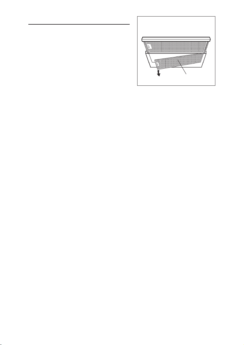
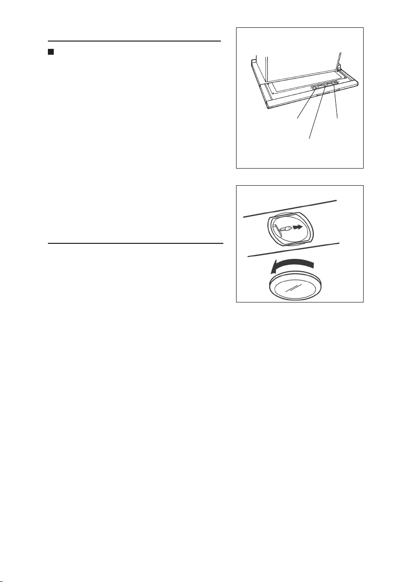
Grease filters
The grease filters should be cleaned periodically depending upon use
(approximately every two (2) months).
Use a warm detergent solution. Grease filters are dishwasher safe. Clean all-
metal filters in the dishwasher using a non-phosphate detergent. Discoloration
of the filter may occur if using phosphate detergent or as a result of local water
conditions — but this will not affect filter performance. This discoloration is not
covered by the warranty.
To remove the grease filters, push the retainer near the handle inwards and pull
the filter downwards (Fig. 10); open the holder and remove the other filter in the
same way.
Charcoal Filters
The charcoal filters should be changed every 6 months. Rotate the filters to
remove and replace.
FIGURE 10
GREASE FILTERS
Hood Cleaning
Stainless steel is one of the easiest materials to keep clean. Occasional care will
help preserve its fine appearance.
Cleaning tips:
• Hot water with soap or detergent is all that is usually needed.
• Follow all cleaning by rinsing with clear water. Wipe dry with a clean, soft cloth to
avoid water marks.
• For discolorations or deposits that persist, use a non-scratching household cleanser
or stainless steel polishing powder with a little water and a soft cloth.
• For stubborn cases, use a plastic scouring pad or soft bristle brush together with
cleanser and water. Rub lightly in direction of polishing lines or "grain" of the
stainless finish. Avoid using too much pressure which may mar the surface.
• DO NOT allow deposits to remain for long periods of time.
• DO NOT use ordinary steel wool or steel brushes. Small bits of steel may adhere
to the surface causing rust.
• DO NOT allow salt solutions, disinfectants, bleaches, or cleaning compounds to
remain in contact with stainless steel for extended periods. Many of these compounds contain chemicals which may be harmful. Rinse with water after exposure and wipe dry with a clean cloth.
• Surfaces should be cleaned with warm water and mild detergent only.
- 9 -
Page 10
OPERATION
Note: Avoid using food products that
produce flames under the range hood.
Controls
1. Blower Switch
Left position (0) - blower is turned off
Right position (1) - blower is turned on
and off automatically by opening and
closing the canopy hood/control.
2. Speed Switch - Makes it possible to
select the motor operating speed.
3. Light Switch
Central position (0) - light is turned off
Left position (AUT) - light is turned on
and off automatically by opening and
closing the cano-py hood/control.
Right position (MAN) - light ON/OFF.
FIGURE 11
BLOWER
SWITCH
FIGURE 12
LIGHT
SWITCH
SPEED
SWITCH
HALOGEN BULBS
This range hood requires 2 halogen bulbs
(Type T3, 12 Volt, 20 Watt Max, G-4 Base).
ALWAYS SWITCH OFF THE ELECTRICITY
SUPPLY BEFORE CARRYING OUT ANY
OPERATIONS ON THE APPLIANCE.
To change bulbs:
1. Loosen the ring nut by turning it
counterclockwise.
2. Pull the bulb downwards to remove - DO NOT ROTATE. CAUTION: BULB
MAY BE HOT!
3. Replace with Type T3, 12 Volt, 20 Watt Max, G-4 Base halogen bulb. Do not
touch replacement bulb with bare hands!
- 10 -
Page 11

WARRANTY
ONE YEAR LIMITED WARRANTY FOR BROAN PRODUCTS
Broan-NuTone LLC (Broan-NuTone) warrants to the original consumer purchaser
of Broan Elite products that such products will be free from defects in materials or
workmanship for a period of one year from the date of original purchase. THERE
ARE NO OTHER WARRANTIES, EXPRESS OR IMPLIED, INCLUDING, BUT NOT
LIMITED TO, IMPLIED WARRANTIES OR MERCHANT ABILITY OR FITNESS FOR
A PARTICULAR PURPOSE.
During this one-year period, Broan-NuTone will, at its option, repair or replace,
without charge, any product or part which is found to be defective under normal use
and service.
THIS WARRANTY DOES NOT EXTEND TO FLUORESCENT LAMP STARTERS,
TUBES, HALOGEN AND INCANDESCENT BULBS, FUSE, FILTERS, DUCTS, ROOF
CAPS, WALL CAPS AND OTHER ACCESSORIES FOR DUCTING. This warranty
does not cover (a) normal maintenance and service or (b) any products or parts
which have been subject to misuse, negligence, accident, improper maintenance
or repair (other than by Broan-NuTone), faulty installation or installation contrary to
recommended installation instructions.
The duration of any implied warranty is limited to the one-year period as specified
for the express warranty. Some states or provinces do not allow limitation on how
long an implied warranty lasts, so the above limitation may not apply to you.
BROAN-NUTONE'S OBLIGATION TO REPAIR OR REPLACE, AT BROANNUTONE'S OPTION, SHALL BE THE PURCHASER'S SOLE AND EXCLUSIVE
REMEDY UNDER THIS WARRANTY. BROAN-NUTONE SHALL NOT BE LIABLE
FOR INCIDENTAL, CONSEQUENTIAL OR SPECIAL DAMAGES ARISING OUT OF
OR IN CONNECTION WITH PRODUCT USE OR PERFORMANCE. Some states or
provinces do not allow the exclusion or limitation of incidental or consequential
damages, so the above limitation or exclusion may not apply to you.
This warranty gives you specific legal rights, and you may also have other rights,
which vary from state to state or provinces another. This warranty supersedes all
prior warranties.
To qualify for warranty service, you must (a) notify Broan-NuTone at one of the
addresses stated below or telephone number stated below, (b) give the model
number and part identification and (c) describe the nature of any defect in the
product or part. At the time of requesting warranty service, you must present evidence
of the original purchase date.
In USA - Broan-NuTone LLC; 926 W. State Street, Hartford, Wisconsin 53027
www.broan.com 800-558-1711
In Canada - Broan-NuTone Canada Inc.; 1140 Tristar Drive, Mississauga, ON L5T 1H9
www.broan.ca 877-896-1119
- 11 -
Page 12

LISEZ ET CONSERVEZ CES INSTRUCTIONS
POUR USAGE DOMESTIQUE SEULEMENT
!
AVERTISSEMENT
POUR RÉDUIRE LES RISQUES D’INCENDIE, D’ÉLECTROCUTION OU DE BLESSURES
CORPORELLES, OBSERVEZ LES INSTRUCTIONS SUIVANTES :
1. N’utilisez cet appareil que de la façon prévue par le manufacturier. Si vous avez des
questions, contactez le manufacturier à l’une des adresses ou numéros de téléphone
indiqués dans la garantie.
2. Avant de nettoyer ou de réparer l’appareil, coupez le courant au panneau d’alimentation
et verrouillez-en l’accès afin d’éviter sa remise en marche accidentelle. Si le panneau
d’alimentation ne peut être verrouillé, apposez un avertissement bien en évidence, par
exemple une étiquette de couleur vive.
3. Les travaux d’installation et de raccordement électrique doivent être effectués par du
personnel qualifié en respectant les normes et règlements en vigueur, y compris les
normes et codes de bâtiment en matière de prévention d’incendie.
4. Une circulation d’air efficace est requise afin d’assurer la combustion et l’évacuation
complète des gaz par la cheminée des appareils à combustion pour prévenir les retours
de cheminée. Conformez-vous aux instructions et aux standards de sécurité des
manufacturiers d’appareils de chauffage, tels qu’ils sont publiés par la National Fire
Protection Association (NFPA) et l’American Society for Heating, Refrigeration and Air
Conditioning Engineers (ASHRAE) ainsi que les responsables des codes locaux.
5. Lorsque vous coupez ou perforez un mur ou un plafond, prenez garde de ne pas
endommager les fils électriques ou autre installation qui pourraient y être dissimulés.
6. Les ventilateurs avec conduits doivent toujours évacuer l’air à l’extérieur.
7. N’utilisez pas cet appareil avec une commande de vitesse à semi-conducteur additionnelle.
8. Afin de réduire le risque d’incendie, n’utilisez que des conduits en métal.
9. Cet appareil doit être relié à une mise à la terre.
10. Lorsqu’une réglementation est en vigueur localement et qu’elle comporte des exigences
d’installation et/ou de certification plus restrictives, lesdites exigences prévalent sur
celles de ce document et l’installateur entend s’y conformer à ses frais.
AFIN DE RÉDUIRE LE RISQUE DE FEU DE CUISINIÈRE :
A. Ne laissez jamais les appareils de cuisson sans surveillance lorsqu’ils sont réglés à feu
vif. Les débordements engendrent de la fumée et des déversements graisseux pouvant
s’enflammer. Chauffez l’huile lentement, à feu doux ou moyen.
B. Mettez toujours la hotte en marche lorsque vous cuisinez à feu vif ou que vous cuisinez
des mets flambés (par ex. : Crêpes Suzette, Cerises Jubilé, Steak au Poivre Flambé).
C. Nettoyez régulièrement la (les) roue(s) du moteur de ventilateur. Ne laissez pas la
graisse s’accumuler sur le ventilateur ou les filtres.
D. Utilisez le bon format de casserole. Servez-vous toujours de casseroles et d’ustensiles
appropriés à la dimension de la surface chauffante.
!
AVERTISSEMENT
AFIN D’ÉVITER TOUT RISQUE DE BLESSURES LORS D’UN FEU DE CUISINIÈRE,
OBSERVEZ LES INSTRUCTIONS SUIVANTES* :
1. ÉTOUFFEZ LES FLAMMES à l’aide d’un couvercle hermétique, une plaque à
biscuits ou un plateau en métal, puis éteignez le brûleur. ATTENTION DE NE PAS
VOUS BRÛLER. SI LES FLAMMES NE S’ÉTEIGNENT PAS IMMÉDIATEMENT, PRENEZ
SOIN D’ÉVITER LES BRÛLURES, SORTEZ ET APPELEZ LES POMPIERS.
2. NE PRENEZ JAMAIS EN MAIN UNE POÊLE OU UNE CASSEROLE QUI A PRIS FEU;
vous pourriez vous brûler.
3. N’UTILISEZ PAS D’EAU, ni de linge à vaisselle ou de serviettes mouillés; cela pourrait
occasionner une violente explosion de vapeur.
4. Utilisez un extincteur SEULEMENT LORSQUE :
A. Vous savez qu’il s’agit d’un extincteur de classe ABC et que vous en connaissez le
fonctionnement.
B. L’incendie est petit et limité à l’endroit où il a débuté.
C. Les pompiers ont été avisés.
D. Vous pouvez combattre l’incendie en ayant accès à une sortie de secours.
*Tirées du “Kitchen Fire Safety Tips” publié par la NFPA.
- 12 -
Page 13

!
ATTENTION
1. Pour usage intérieur seulement.
2. Pour réduire tout risque d’incendie et évacuer correctement l’air, assurez-vous d’évacuez
l’air à l’extérieur. N’évacuez pas l’air dans des espaces clos comme l’intérieur des murs
ou un plafond, dans le grenier, faux-plafond ou garage.
3. Faites très attention lors de l’utilisation de produits de nettoyage ou de détergents.
4. Évitez d’utiliser des produits alimentaires pouvant s’enflammer sous la hotte de cuisinière.
5. N’utilisez cet appareil que pour une ventilation générale. Ne l’utilisez pas pour évacuer
des vapeurs ou des matières dangereuses ou explosives.
6. Afin d’éviter tout dommage au moteur et de débalancer ou de rendre bruyante la roue du
moteur, gardez votre appareil à l’abri des poussières de gypse et de
construction/rénovation, etc.
7. Le moteur de votre hotte possède une protection thermique qui éteindra automatiquement
le moteur s’il devient surchauffé. Il redémarrera automatiquement une fois refroidi. Si le
moteur continue à s’éteindre et à se remettre en marche, faites vérifier votre hotte.
8. Pour une meilleure évacuation des odeurs de cuisson, le bas de votre hotte devrait
être à un minimum de 24 po et à un maximum de 30 po au-dessus de la surface
de cuisson.
9. En raison de la grande dimension et du poids de cet appareil, il est recommandé de
confier l’installation à deux personnes.
10. Nous vous recommandons de lire l’étiquette indiquant les caractéristiques de votre
hotte pour de plus amples renseignements et exigences.
11. Appareil avec fonctionnement automatique. Pour réduire les risques de blessures,
débrancher avant l’entretien.
12. Ne pas utiliser un ventilateur avec un cordon ou une fiche endommagé. Jeter ou retourner
à un centre de service autorisé pour examen et / ou réparation.
- 13 -
Page 14

PRÉPARATION DE LA HOTTE
Retirer la hotte de l’emballage, puis vérifier le contenu.
Vous devez avoir:
1 - Hotte
1 - Sachet de pièces (B080810359) comprenant :
3 - Vis de montage (3,9 mm x 6 mm tête fraisée)
1 - Sachet de pièces (B080810871) comprenant :
1 - Bride de montage droite
1 - Bride de montage gauche
2 - Vis de montage (M4 x 8 mm)
2 - Rondelles
4 - Vis de montage (3,9 mm x 9,5 mm)
4 - Vis de montage (4,2 mm x 15 mm)
4 - Vis de montage (4,2 mm x 32 mm)
1 - Collier d’évacuation
1 - Barre entretoise
1 - Instructions pour l’installation
COLLIER
D’ÉVACUATION
BRIDE DE
MONTAGE
DROITE
BRIDE DE
MONTAGE
GAUCHE
2
RONDELLES
BARRE
ENTRETOISE
4 VIS DE MONTAGE (4,2 x 15 mm)
4 VIS DE MONTAGE (4,2 x 32 mm)
3 VIS DE MONTAGE (3,9 x 6 mm)
4 VIS DE MONTAGE (3,9 x 9,5 mm)
2 VIS DE MONTAGE (M4 x 8 mm)
- 14 -
Page 15

INSTALLATION DU SYSTÈME
DE CONDUITS
(
HOTTES À ÉVACUATION EXTÉRIEURE
SEULEMENT
NOTE : Pour réduire le risque d’incendie,
n’utilisez que des conduits en métal.
)
FIGURE 1
CAPUCHON DE TOIT
CONDUIT ROND
DE 6 PO
1. Déterminer par où passera le conduit, entre
votre hotte et l’extérieur.
2. Un conduit droit et court permettra à votre
hotte de fonctionner plus efficacement.
3. Un conduit long avec des coudes et des
transitions réduira la performance de votre
hotte. En utiliser le moins possible. Pour
une grande distance, il faut un conduit
d’évacuation d’air au diamètre plus grand.
4. Installer un capuchon de toit ou de mur.
Relier le conduit circulaire en métal au
capuchon, puis acheminer le conduit
jusqu’à l’emplacement de votre hotte.
Sceller hermétiquement les raccords à
l’aide de ruban à conduits.
INSTALLATION DE LA
BARRE ENTRETOISE
Afin de compenser des vides éventuels de
profondeur entre l'appareil et le mur, une
BARRE ENTRETOISE en plastique a été
prévue; elle doit être fixée sur l'arrière de
l'appareil au moyen des trois vis (3,9 mm x 6 mm).
Les 3 vis à utiliser se trouvent dans le sachet
des accessoires joint à la barre entretoise
de plastique.
Couper la barre entretoise selon la distance
qui doit être compensée.
HOTTE
DE 24 PO À 30 PO
AU-DESSUS
DU PLAN DE CUISSON
FIGURE 2
VIS DE MONTAGE
(3,9 x 6 mm)
CAPUCHON
DE MUR
COUDE
ROND
- 15 -
Page 16

BRANCHEMENT ÉLECTRIQUE
AVERTISSEMENT : Cette hotte de cuisinière
doit être correctement reliée à une mise à la
terre. L’installation doit être effectuée par du
personnel qualifié en vertu des codes
électriques nationaux et locaux en vigueur.
INSTRUCTIONS POUR MISE À LA TERRE
Cet appareil doit être relié à la terre. En cas
de court-circuit électrique, la mise à la terre
réduit le risque d’électrocution en fournissant un
câble d’évacuation du courant. Cet appareil
est muni d’un cordon équipé d’un câble de
mise à la terre avec fiche de mise à la terre.
La fiche doit être branchée dans une
prise de courant correctement installée et mise à la terre.
AVERTISSEMENT - Consultez un électricien si les instructions de mise à la
terre ne sont pas tout à fait compréhensibles ou si un doute persiste quant à
savoir si l’appareil est correctement relié à la terre. Ne pas utiliser de rallonge
électrique. Si le cordon d’alimentation est trop court, demandez à un électricien
d’installer une prise de courant près de l’appareil.
Placer la prise à une distance maximale de 33 7/16 po de l’endroit où le fil sort
de la hotte (voir Figure 3).
FIGURE 3
33-7/16 PO
(85 CM)
MAX
- 16 -
Page 17

INSTALLATION
La hotte doit être encastrée dans
une armoire.
ATTENTION: Il faut au moins 2 personnes
pour monter cet appareil; il est conseillé de
confier les opérations d'installation à des
spécialistes.
Pour les mesures de l’armoire, voir la Figure 4.
FIGURE 4
12-3/16 po
(31 cm)
1-3/4 po x 1-3/4 po
(4,5 cm x 4,5 cm)
Installation directe à l’armoire
Réf. à la Figure 5.
1. Pratiquer les 4 trous de fixation requis
dans l’armoire et découper celui pour
le conduit d’évacuation et delui du
cordon électrique.
2. Amener la hotte près du bas de
l’armoire et la fixer à celle-ci à
l’aide des 4 vis autotaraudeuses
(4,2 mm x 32 mm) fournies.
Fixation avec brides de montage
Réf. à la Figure 6.
1. Sortir du sachet des accessoires
les 2 brides de montage (S) et les
4 vis fournies (4,2 mm x 15 mm).
2. Fixer les brides de montage à
l’armoire en s’assurant de les
positionner correctement.
3. Régler l’inclinaison de la hotte à
l’aide des 4 vis de mise à niveau
(3,9 mm x 9,5 mm).
4. Fixer la hotte aux brides de
montage en utilisant les 2 vis
(M4 x 8 mm) et rondelles.
FIGURE 6
7-1/2 po
(19 cm)
2-3/16 po
(5,5 cm)
24 po - 30 po
S
FIGURE 5
8-9/16 po
(21,7 cm)
24 po (60,96 cm)
30 po (76,20 cm)
VIS DE MONTAGE
(4,2 mm x 32 mm)
18-1/8 po (24 po)
24-1/8 po (30 po)
10-1/4 po (26 cm)
12 po
MIN.
(30,5 CM)
3-1/8 po
(7,9 cm)
VIS DE MONTAGE
(4,2 MM X 15 MM)
VIS DE MONTAGE
(M4 X 8 MM)
- 17 -
12-3/16 po
(31 cm)
VIS DE
MISE À NIVEAU
(3,9 MM X 9,5 MM)
Page 18

RACCORDEMENT
FIGURE 7
DES CONDUITS
(
HOTTES À ÉVACUATION EXTÉRIEURE SEULEMENT
1. Installer le collier d’évacuation dans le
raccord de conduit de la hotte (Fig. 7).
2. Utiliser un conduit circulaire en métal de
6 po pour relier le raccord de conduit de
la hotte au conduit menant à l’extérieur.
Voir la Figure 8.
3. Sceller hermétiquement les joints du
conduit à l’aide de ruban à conduits.
4. Brancher le cordon d’alimentation de
l’appareil dans la prise.
)
COLLIER
D’ÉVACUATION
RACCORD
DE
CONDUIT
FIGURE 8
CONDUIT
DE MÉTAL
DE 6 po
DE
DIAMÈTRE
INSTALLATION DES FILTRES
À CHARBON
(HOTTES À RECIRCULATION)
1. Installer le collier d’évacuation dans le
raccord de conduit de la hotte (Fig. 7).
2. Voir la Figure 8B. Raccorder un conduit
en métal rond de 6 po à une ouverture
d’évacuation de façon à ce que l’air soit
acheminé à l’extérieur de l’armoire et
renvoyé dans la pièce.
3. Placer les filtres aux extrémités
du ventilateur.
4. Faire tourner pour bloquer les filtres
en place.
5. Acheter l’ensemble de rechange de
filtres à charbon (comprend 2 filtres)
chez votre fournisseur.
No de pièce : FILTEREB40.
- 18 -
FIGURE 8B
CONDUIT
DE MÉTAL
DE 6 po
DE
DIAMÈTRE
FIGURE 9
FILTRES À
CHARBON
Page 19

ENTRETIEN
Un entretien adéquat de votre hotte de
cuisinière garantira une excellente performance.
AVANT DE RÉPARER OU DE NETTOYER
L’APPAREIL, COUPEZ L’ALIMENTATION
ELECTRIQUE EN VERROUILLANT LE
PANNEAU DE SERVICE AFINE D’ÉVITER
SA REMISE EN MARCHE ACCIDENTELLE.
SI LE PANNEAU DE SERVICE NE PEUT
ÉTRE VERROUILLÉ, Y FIXER UN
AVVERTISEMENT EN ÉVIDENCE, TELLE
QU’UNE ÉTIQUETTE DE COULEUR VIVE.
Filtres à graisses
Les filtres à graisses doivent être nettoyés périodiquement en fonction de l’usage
(approximativement tous les deux (2) mois).
Utiliser une solution détergente chaude. Les filtres à graisses sont lavables
au lave-vaisselle. Nettoyer les filtres fabriqués entièrement de métal au lave-
vaisselle à l’aide d’un détergent sans phosphate. L’utilisation d’un détergent
avec phosphates ainsi que les conditions locales de l’eau peuvent entraîner
une décoloration des filtres, sans toutefois affecter leur performance. Cette
décoloration n’est pas couverte par la garantie.
Pour retirer les filtres à graisses, appuyer sur le taquet de la poignée et tirer le filtre
vers le bas (Fig. 10); étirer complètement la partie coulissante de la hotte et enlever
l’autre filtre de la même manière.
Filtres à charbon
Les filtres à charbon doivent être remplacés tous les 6 mois. Faire tourner les filtres
pour les enlever et les remplacer.
FIGURE 10
FILTRES À GRAISSES
Nettoyage de votre hotte
L’acier inoxydable est l’un des matériaux les plus faciles à nettoyer. Un entretien
occasionnel permettra de conserver sa belle apparence. Conseils de nettoyage :
• De l’eau chaude et du savon ou un détergent est tout ce qui est normalement requis.
• Après le nettoyage, rincer toujours à l’eau claire. Essuyer la surface avec un
chiffon propre et doux pour éviter les stries.
• Pour les ternissures ou les dépôts tenaces, utiliser un nettoyant domestique
non abrasif ou une poudre à polir l’acier inoxydable avec un peu d’eau et un
chiffon doux.
• Pour la saleté rebelle, utiliser un tampon à récurer en plastique ou une brosse
à poils doux avec un nettoyant et de l’eau. Frotter doucement dans le sens
des lignes de polissage ou du « grain » de l’acier. Éviter de trop appuyer au
risque de gâcher la surface.
• NE PAS LAISSER les dépôts s’accumuler trop longtemps.
• NE PAS UTILISER une laine d’acier ordinaire ou une brosse d’acier. De petites
particules d’acier risqueraient d’adhérer à la surface et de la faire rouiller.
• NE PAS LAISSER longtemps en contact avec l’acier inoxydable une solution
saline, un désinfectant, de l’eau de Javel ou tout autre produit détachant. Bon
nombre de ces nettoyants contiennent des produits chimiques pouvant en
altérer la surface. Après l’utilisation du nettoyant, rincer la surface à l’eau,
puis l’essuyer avec un chiffon propre.
Nettoyer les surfaces uniquement à l’eau tiède avec un détergent doux.
- 19 -
Page 20

FONCTIONNEMENT
NOTE : Eviter d’utiliser des produits
alimentaires qui produisent des flammes
sous la hotte.
Commandes
1. Bouton du ventilateur
En position gauche (0) – Ventilateur arrêté En
position droite (1) – fonctionnement et arrêt
automatiques du ventilateur en ouvrant et en
fermant la partie coulissante de la hotte.
2. Bouton de vitesse - Il permet le réglage des
vitesses du ventilateur.
3. Bouton éclairage:
Position centrale de l’interrupteur (0) – lumière
éteinte. Position gauche (AUTO) – allumage et
extinction automatiques de la lumière en ouvrant
et en fermant la partie coulissante de la hotte.
Position droite (MAN) – lumière allumée.
FIGURE 11
BOUTON DU
VENTILATEUR
BOUTON
DE
VITESSE
BOUTON
ÉCLAIRAGE
AMPOULES HALOGENES
FIGURE 12
L’éclairage de cette hotte est produit par 2
ampoules halogènes (Type T3, 12 Volts,
20 Watts Max à culot G-4).
AVANT DE PROCÉDER À QUELCONQUE
OPÉRATION, DÉBRANCHEZ L’APPAREIL.
Pour changer les ampoules :
1. Dévissez la bague dans le sens contraire
aux aiguilles d’une montre.
2. Enlevez l’ampoule en tirant sur le côté (NE
LA FAITES PAS TOURNER). ATTENTION :
L’AMPOULE PEUT ÊTRE CHAUDE!
3. Remplacer par une ampoule ayant les mêmes caractéristiques (Type T3, 12
Volt, 20 Watt Max, à culot G-4 Base). Ne touchez pas l’ampoule neuve de vos
mains nues!
- 20 -
Page 21

GARANTIE
GARANTIE LIMITÉE DE UN AN DE BROAN
Broan-NuTone LLC (Broan-NuTone) garantit à l'acheteur original que les produits
BROAN Elite vendus en vertu de la présente sont libres de tout vice de matériau
ou de fabrication pour une période de un an à compter de la date d'achat originale.
CETTE GARANTIE NE COMPORTE AUCUNE AUTRE GARANTIE, EXPRESSE
OU TACITE, Y COMPRIS, MAIS SANS S'Y LIMITER, LES GARANTIES TACITES
DE VALEUR MARCHANDE OU D'ADAPTATION À UN USAGE PARTICULIER.
Durant cette période de un an, Broan-NuTone réparera ou remplacera gratuitement,
à sa discrétion, tout produit ou toute pièce jugés défectueux dans des conditions
normales d'utilisation.
CETTE GARANTIE NE S'APPLIQUE PAS AUX TUBES FLUORESCENTS ET AUX
STARTERS, NI AUX AMPOULES HALOGÈNES OU INCANDESCENTES,
FUSIBLE, FILTRES, CONDUITES, CHAPEAUX DE TOIT, CHAPEAUX DE MUR
ET AUTRES ACCESSOIRES POUR CANALISATIONS. Cette garantie ne couvre
pas (a) les frais d'entretien ou de service normaux ni (b) tout produit ou toute pièce
soumis à une utilisation inadéquate, une négligence, un accident, un entretien ou
une réparation inadéquats (autres que ceux effectués par Broan-NuTone), une
mauvaise installation ou une installation contraire aux instructions recommandées.
La durée de toute garantie tacite est limitée à la période de un an stipulée pour la
garantie expresse. Certains États ou provinces ne permettent pas de limites quant
à la durée d’une garantie implicite. La restriction susmentionnée peut donc ne pas
s'appliquer dans votre cas.
BROAN-NUTONE’S L'OBLIGATION POUR BROAN-NUTONE DE RÉPARER OU
DE REMPLACER LE PRODUIT, À SA DISCRÉTION, CONSTITUE LE SEUL
RECOURS DE L'ACHETEUR EN VERTU DE CETTE GARANTIE. BROAN-NUTONE
NE PEUT PAS ÊTRE TENUE RESPONSABLE DE TOUT DOMMAGE INDIRECT,
CONSÉCUTIF OU ACCESSOIRE DÉCOULANT DE L'UTILISATION OU DU
RENDEMENT DU PRODUIT. Certains États ou provinces interdisent l'exclusion
ou la restriction des dommages indirects ou consécutifs. La restriction
susmentionnée peut donc ne pas s'appliquer dans votre cas.
La présente garantie vous confère des droits spécifiques reconnus par la loi.
D'autres droits pourraient également vous être accordés selon la législation locale
en vigueur. La présente garantie remplace toutes les autres garanties précédentes.
Pour le service sous garantie, vous devez (a) aviser Broan-NuTone à l'une des
adresses ou numéros de téléphone mentionnés ci-dessous, (b) indiquer le
numéro de modèle et d'identification de la pièce et (c) décrire la défectuosité du
produit ou de la pièce. Lors d’une réclamation, vous devez présenter une preuve
de la date d'achat originale.
Aux Étast- Unis - Broan-NuTone LLC; 926 W. State Street, Hartford, Wisconsin
53027 www.broan.com 800-558-1711
Au Canada - Broan-NuTone Canada Inc.; 1140 Tristar Drive, Mississauga, ON L5T 1H9
www.broan.ca 877-896-1119
- 21 -
Page 22

LEA Y CONSERVE ESTAS INSTRUCCIONES
!
INDICADO PARA EL USO EN COCINAS DOMESTICAS
!
ADVERTENCIA
PARA EVITAR EL RIESGO DE INCENDIO, CORTOCIRCUITO O DAÑO PARA LAS
PERSONAS, OBSERVE ATENTAMENTE LAS SIGUIENTES NORMAS:
1. Use esta unidad solamente de la manera indicada por el fabricante; si tiene dudas,
póngase en contacto con éste a la dirección o teléfono indicados en la garantía.
2. Antes de hacer una revisión o de limpiar la unidad, desconéctela de la red para evitar
que se encienda de manera accidental. En el caso de que éste no pueda ser desactivado, se indicará nel panel de servicio.
3. El montaje y la instalación eléctrica debe hacerlos un técnico especializado siguiendo
las normas estándar e incluyendo aquellas de construcción anti incendio.
4. Necesita aire suficiente para una apropiada combustión y escape de gases a través del
tubo del depósito de quema de combustible. Para evitar que el humo aspirado vuelva a
la cocina, siga las directivas del fabricante y las normas estándar de siguridad así como
las normas publicadas por la Asociación de prevención de incendios (NFPA) y la Socie-
dad americana de especialistas en cale-facción, refrigeración y aire acondicionado y
además las normas de las autoridades locales.
5. Hacer un corte o un taladro en la pared o en el techo no debe dañar la instalación
eléctrica u otras instalaciones ocultas en la pared.
6. Los conductos ventiladores deben siempre desalojar al exterior.
7. No use esta unidad con dispositivo de control de la velocidad a estado sólido.
8. Para evitar el riesgo de incendio, use solamente conductos de metal.
9. Esta unidad tiene que ser conectada a tierra.
10. Cuando las regulaciones locales comprenden la instalación y los requisitos más restrictivos
/ o certificación, los requisitos anteriores prevalecen sobre las del presente documento y
el instalador se compromete a cumplir con estas exigencias a sus propios gastos.
PARA EVITAR EL RIESGO DE FUEGO POR ALTO NIVEL DE GRASA:
A. Nunca abandone los quemadores con el fuego alto. La cocción causa humo y restos
de grasa que pueden arder. Caliente el aceite a fuego medio o bajo.
B. Encienda siempre la campana cuando cocine a fuego alto o cuando cocine alimentos
fácilmente inflamables. (por ejemplo Crêpes Suzette, Cerezas Jubilee, Ternera
flambeada con granos de pimienta).
C. Limpie con frecuencia los ventiladores. No se debe acumular grasa en el ventilador o
en el filtro.
D. Usa el tamaño de cazuela apropiado. Use siempre utensilios de cocina de tamaño y
material adecuados.
ADVERTENCIA
PARA EVITAR EL RIESGO DE DAÑOS A PERSONAS EN CASO DE FUEGO POR ALTO
NÍVEL DE GRASA, TENGA EN CUENTA LO SIGUIENTE:*
1. SOFOQUE LA LLAMA con una tapadera apropiada, una bandeja metálica ó un utensilio
de cocína que pueda cubrirla, despues, apague el quemador. ACTÚE CON
PRECAUCÍON PARA EVITAR QUEMADURAS. SI LA LLAMA NO SE EXTINGUE
INMEDIATAMENTE , SALGA Y LLAME A LOS BOMBEROS.
2. NUNCA COJA UNA SARTEN EN LLAMAS, porque corre el riesgo de quemarse.
3. NO USE AGUA ni paños o toallas húmidas porque puede provocarse una violenta
humareda.
4. Use un extintor SOLAMENTE si:
A. Posee un extintor de clase ABC y sabe perfectamente cómo usarlo.
B. El fuego es pequeño y está controlado en el mismo sitio en que empezó.
C. Ha llamado con anterioridad a los bomberos.
D. Puede combatir el fuego retrocedíendo hacia la salida.
* Basado en “Seguridad antifuego en la cocína” publicado por NFPA.
- 22 -
Page 23

!
ADVERTENCIA
1. Para uso en interiores.
2. Para reducir el riesgo de incendios y para evacuar correctamente los humos, asegurarse
de haber realizado una conducción del aire hasta el exterior. No expulsar los humos en
espacios cerrados por paredes o techos, áticos, espacios angostos o garajes.
3. Prestar la máxima atención al utilizar productos de limpieza o detergentes.
4. Evitar el uso de productos alimentarios que puedan inflamarse bajo la campana.
5. Sólo para ventilación total. No use gases de escape peligrosos o materiales y vapores
explosivos.
6. Para evitar daños en el funcionamiento del motor e impulsores ruidosos y/o desequilibrados, mantenga alejados de la unidad de encendido pulverizadores en seco o polvo.
7. El motor tiene un nivel de sobrecarga térmica que apaga automáticamente el motor
cuando se ha recalentado excesivamente. El motor se pone de nuevo en fincionamento
cuando la temperatura baja. Si el motor comienza a encenderse y a apagarse, deberá
hacer una revisión de éste.
8. Para limpiar mejor las impurezas al cocinar, la distancia entre la parte inferior de la
campana y la zona de cocción debe ser mínimo 24” - maximo 30”.
9. Debido a su gran tamaño y peso, se recomienda su montaje por parte de dos técnicos
esperializados.
10. Se recomienda leer la placa de caracteristicas del producto para ulterior información.
11. Aparato con automatismo. Para evitar el riesgo de daños, colocar el interruptor del panel
de servicio en la posición OFF antes de mantenimiento.
12. No opere ningún aparato con un cable o enchufe dañado. Deseche el ventilador o el
retorno a un centro de servicio autorizado para su revisión y / o reparación.
- 23 -
Page 24

PREPARE LA CAMPANA
Sacar la campana de l’embalaje y controlar el contenido.
Recivireis:
1 - Campana
1 - Bolsita (B080810359) con:
3 - Tornillos de montaje (3,9 x 6 mm cabeza plano)
1 - Bolsita (B080810871) con:
1 - Estribo derecho
1 - Etrier izquierdo
2 - Tornillos de montaje (M4 x 8 mm)
2 - Arandelas
4 - Tornillos de montaje (3,9 x 9,5 mm)
4 - Tornillos de montaje (4,2 x 15 mm)
4 - Tornillos de montaje (4,2 x 32 mm)
1 - Casquillo
1 - Distanciador
1 - Instrucciones para instalación
CASQUILLO
DISTANCIADOR
4 TORNILLOS DE MONTAJE (4,2 x 15 mm)
4 TORNILLOS DE MONTAJE (4,2 x 32 mm)
ESTRIBO
IZQUIERDO
3 TORNILLOS DE MONTAJE (3,9 x 6 mm)
4 TORNILLOS DE MONTAJE (3,9 x 9,5,mm)
2 TORNILLOS DE MONTAJE (M4 x 8 mm)
ESTRIBO
DERECHO
2 ARANDELAS
- 24 -
Page 25

INSTALACION DEL TUBO DE
EXTRACCION
(SÓLO CAMPANAS CON CONDUCTO)
FIGURE 1
UBIERTA DEL
TEJADO
NOTA: para evitar el riesgo de incendio, use
solamente material de metal.
1. Decida donde va a colocar el tubo de
extracción entre la campana y la parte
exterior.
2. Un recorrido de tubo corto y recto permitirá
a la campana funcionar de manera más
eficaz.
3. Los recorridos largos de tubo, codos y
manguitos impiden el buen
funcionamiento de la campana. Use el
menor número de ellos posible. Para usos
prolongados es necesario un tubo de
evacuación del aire de mayor diámetro.
4. Instale una cubierta ó una tapa. Una el
tubo de metal a la cubierta y retroceda
hasta la posición de la campana. Use une
cinta para precintar las juntas entre las
partes del entubado.
INSTALACION
DISTANCIADOR
A fin de compensar los posibles huecos entre
el aparato y la pared, se ha previsto un
DISTANCIADOR de plástico, que debe
sujetarse en la trasera del aparato, por medio
de 3 tornillos (3,9 x 6 mm). Los 3 tornillos se
encuentran en el saco de accesorios adjunto
al distanciador.
Cortar la pieza de plástico, según la distancia
a cubrir entre el aparato y la pared.
CAMPANA
24” (61cm) A 30” (76cm)
POR ENCIMA
DE LA ZONA DE
COCCIÓN
FIGURE 2
TORNILLOS DE
MONTAJE
(3,9 x 6 mm)
TUBO DE 6”
MANGUITO
TAPA
PARED
- 25 -
Page 26

INSTALACIÓN ELECTRICA
FIGURE 3
Nota: Este tipo de campana tiene que ser
conectada a tierra cuidadosamente. La
unidad debe instalarla un técnico electricista
siguiendo las normas nacionales y locales.
INSTRUCCIONES DE CONEXIÓN A TIERRA
Este aparato se debe conectar a tierra. En
caso de cortocircuito, la conexión a tierra
reduce el riego de electrocución ya que
posee un hilo de descarga a tierra para la
corriente. Este aparato está equipado con un
cable que posee un hilo de toma de tierra
con una clavija de tierra. La clavija se debe
conectar a un enchufe instalado
correctamente y conectado a tierra.
ADVERTENCIA- una conexión a tierra incorrecta puede provocar riesgos de
electrocución.
Consulte a un electricista calificado si no se entienden o si existe alguna duda
sobre la correcta conexión a tierra.
No utilice un cable de prolongación. Si el cable proporcionado es demasiado
corto, póngase en contacto con un electricista calificado para que instale un
enchufe cerca del aparato.
Coloque el enchufe a una distancia máxima de 33-7/16” (85 cm) desde el cable de
la campana (véase figura 3).
33-7/16“
(85 CM)
MAX
- 26 -
Page 27

FIJACIÓN
Este dispositivo debe instalarse dentro de
un armario de pared.
CUIDADO: para montar este aparato se
necesitan al menos 2 personas; le
aconsejamos que lo haga instalar a personal especializado.
Para conocer las medidas del armario de
pared, consulte la Figura 4.
FIGURE 4
12-3/16”
(31 cm)
1-3/4” x 1-3/4”
(4,5 cm x 4,5 cm)
10-1/4” (26 cm)
Fijación al mueble
Consulte la Figura 5.
Realice los 4 agujeros de fijación previstos
en el fondo del armario y corte la abertura
necesaria para la evacuación del aire.
Acerque la campana al fondo del armario
de pared y conecte ambas unidades con
los 4 tornillos de autorroscado (4,2 x 32 mm)
suministrados con el dispositivo.
Fijación con estribos
Consulte la Figura 6.
1. Extraer del saco de accesorios los 2
estribos (S) y los 4 tornillos (4,2 x 15 mm)
que se entregan con el aparato.
2. Fijar los estribos (S) al mueble de pared
prestando atención para colocarlos
correctamente.
3. Regular la inclinación del aparato con
los 4 tornillos (3,9 x 9,5 mm).
4. Fijar el aparato a los estribos, utilizando
los 2 tornillos (M4 x 8 mm) y arandelas.
FIGURE 6
7-1/2”
(19 cm)
2-3/16”
(5,5 cm)
S
FIGURE 5
8-9/16”
(21,7 cm)
24” - 30”
24” (60,96 cm)
30” (76,20 cm)
TORNILLOS DE MONTAJE
(4,2 mm x 32 mm)
18-1/8” (24”)
24-1/8” (30”)
12”
MIN.
(30,5 CM)
3-1/8”
(7,9 cm)
TORNILLOS DE MONTAJE
(4,2 MM X 15 MM)
TORNILLOS DE MONTAJE
(M4 X 8 MM)
- 27 -
12-3/16”
(31 cm)
TORNILLOS DE
MONTAJE
(3,9 MM X 9.5 MM)
Page 28

CONEXIÓN DE LOS TUBOS
FIGURE 7
(CONFIGURACIÓN CON CONDUCTO)
1. Instale el cuello de descarga en el conector
de conducto de la campana de cocina (Fig.
7).
2. Utilice un conducto de metal redondo de
6" (150 mm) para conectar la brida de
descarga de la campana con el tubo de
arriba Fig. 8
3. El conducto tapa todas las juntas,
asegurándolas y volviéndolas herméticas.
4. Conecte la clavija al enchufe.
FIGURE 8 FIGURE 8B
CONDUCTO
DE 6" DE
DIÁMETRO
CONDUCTO
DE 6" DE
DIÁMETRO
CASQUILLO
CUELLO DE
DESCHARGA
INSTALACIÓN FILTROS AL
CARBÓN
(CONFIGURACION SIN TUBO)
1. Instale el cuello de descarga en el conector
de conducto de la campana de cocina (Fig. 7).
2. Consulte la Figura 8B. Conecte un tubo de
metal redondo de 6” (15 cm) que circunda la
abertura de la campana de cocina para que
el aire enviado fuera del mueble de pared
se devuelve a la sala
3. Instale los filtros sobre el aspirador.
4. Gire los filtros para ajustarlos en su sitio.
5. Compre el equipo filtros al carbón (incluye
n.2 filtros) a su proveedor habitual.
Cod. n. FILTEREB40.
- 28 -
FIGURE 9
FILTROS AL
CARBÓN
Page 29

MANTENIMIENTO
Un mantenimiento adecuado de la campana
asegura el funcionamiento correcto del aparato.
ANTES DE REALIZAR OPERACIONES DE
MANTENIMIENTO O LIMPIEZA DE LA
UNIDAD, DESCONECTE LA ALIMENTACIÓN
EN EL PANEL DE SERVICIO Y CIERRE EL
MISMO CON UN CANDADO. DESCONECTAR
EL SERVICIO SIGNIFICA EVITAR LA
CONEXIÓN ACCIDENTAL DE LA ALIMENTACIÓN.
SI NO ES POSIBLE CERRAR EL PANEL DE
SERVICIO CON UN CANDADO, COLOQUE EN
ÉL UN DISPOSITIVO DE SEÑALIZACIÓN
ADECUADO COMO, POR EJEMPLO, UN LETRERO DE ADVERTENCIA.
Filtros antigrasa
Los filtros de grasa deben limpiarse periódicamente según el uso (aproximadamente
cada 2 meses).
Utilice una solución limpiadora tibia. El filtro de grasa es a prueba de lavavajillas.
Limpie todos los filtros de metal en el lavavajillas con un detergente sin fosfatos.
La decoloración del filtro se puede producir si se utiliza detergente con fosfato
o como consecuencia de las condiciones del agua local - pero esto no afectará
el rendimiento del filtro. Esta decoloración no está cubierto por la garantía.
Para desmontar los filtros de grasa, empuje hacia dentro el retén cerca de la manilla
y tire del filtro hacia abajo (Fig. 10); sostenga el soporte y desmonte el otro filtro del
mismo modo.
Filtros al carbón
Los filtros deben cambiarse cada seis meses. Gire los filtros para desenroscarlos y
cambiarlos.
FIGURE 10
FILTROS ANTIGRASA
Limpieza de la campana
El acero inoxidable es uno de los meteriales más fáciles de limpiar, pero sería
aconsejable un especial cuidado en su uso para mantenerla en buen estado. La
campana se puede limpiar de las siguientes maneras:
l Agua caliente con jabón o detergente es la mejor manera para limpiarla.
l Aclárela con agua corriente, séquela con un paño suave y limpio para evitar las
huellas que deja el agua.
l Para las manchas o restos de grasa que persistan, use un producto químico
doméstico que no raye ó un limpiador para acero inoxidable con poca agua y un
paño suave.
l Si las manchas persisten, use un estropajo y un cepillo de cerdas suaves con un
producto limpiador y agua. Frote suavemente en el sentido del pulido o de las
“vetas” del remate del inoxidable. No apriete demasiado porque podría dañar la
superficie.
l No deje que las manchas se acumulen durante mucho tiempo.
l No use utensilios o cepillos de acero. Pequeñas particulas de acero pueden
adherirse y oxidarse.
l No use soluciones salinas, desinfectantes, lejías, o productos de limpieza que
permanezcan en contacto con el acero inoxidable durante largos periodos de
tiempo. Muchos de estos productos contienen componentes químicos que podrían
resultar nocivos. Aclare con agua y seque con un paño limpio.
Las superficies deben limpiarse solamente con agua tibia y detergente no muy
fuerte.
- 29 -
Page 30

FUNCIONAMIENTO
Note: Evite utilizar productos que
produzcan llamas debajo de la campana.
Controles
1. Interruptor del ventilador
Posición izquierda (0) – se apaga el ventilador
Posición derecha (1) – el ventilador se enciende
y apaga automáticamente al abrir y cerrar el
mando de la riostra de la campana.
2. Interruptor de velocidad – Permite regular las
velocidades de funcionamiento del ventilador.
3. Interruptor de Luz
Posición central (0) – se apaga la luz Posición
izquierda (AUT) – la luz se enciende y apaga
automáticamente al abrir y cerrar el mando de la
riostra de la campana.
Posición derecha (MAN) - luz ON/OFF.
FIGURE 11
INTERRUPTOR DEL
VENTILADOR
INTERRUPTOR
DE VELOCIDAD
INTERRUPTOR
DE LUZ
FIGURE 12
LAMPARAS HALOGENAS
Este tipo de campana necesita 2 lámparas
halógenas (Tipo T3, 12 Volt, 20 Watt Max, G-4
Base).
ANTES DE PROCEDER A CUALQUIER
OPERACIÓN, ES NECESARIO DESCONECTAR EL APARATO.
Para cambiar las lámparas:
1. Destornillar la abrazadera en sentido
antihorario.
2. Extraiga la lámpara oblicuamente (NO LA GIRE) - ATENCIÓN: LAS
LÁMPARAS PUEDEN ESTAR CALIENTES.
3. Sustituir con lámparas del tipo (T3, 12 Volt, 20 Watt Max, G-4 Base). No toque la
lámpara de repuesto con las manos desnudas.
- 30 -
Page 31

GARANTIA
GARANTIA BROAN POR UN AÑO
Broan-NuTone LLC (Broan-NuTone) garantiza al consumidor-comprador de sus
productos BROAN Elite que dichos productos no tendrán defectos en los materiales
o fabricación, durante un periodo de un año a partir de la fecha de la compra.NO
HAY OTRO TIPO DE GARANTIAS QUE INCLUYAN O SE LIMITEN
EXCLUSIVAMENTE A GARANTIAS IMPLICITAS O DE CAPACIDAD COMERCIAL
O CONVENIENCIA PARA UN PROPOSITO ESPECIFICO.
Durante el periodo de un año, Broan-NuTone, si lo estima conveniente, reparará o
reemplazará sin gastos para el usuario cualquier producto o parte de éste que sea
defectuosos habiéndose usado correctamente.
ESTA GARANTIA NO CUBRE: ESTARTER DE NEON, NEON, LÁMPARAS
HALÒGENAS, LÁMPARAS DE ILUMINACIÓN, FUSIBLE, FILTROS, CONDUCTOS,
TAPAS DE TECHO, TAPAS DE PARED Y OTROS ACCESORIOS PARA LOS
CONDUCTOS. Tampoco cubre el mantenimiento ni los productos o partes de éstos
que hayan sido usados de forma incorrecta, con negligencia, rotos accidentalmente
o por una incorrecta manutención ó reparación (distinta da la realizada por BroanNuTone), montaje incorrecto ó instalación que no se ajuste a las instrucciones de
montaje indicadas.
Le duración de la garantía se limita al periodo de un año como está especificado
en la garantía explicita. Algunos paises o provincias no permiten un limite en la
duración de la garantía implicita; si es asi en su caso, esta limitación arriba indicada
podría no aplicarse.
LA PRESENTE GARANTIA CUBRIRA EXCLUSIVAMENTE AL COMPRADOR LOS
SERVICIOS DESCRITOS ANTERIORMENTE. BROAN-NUTONE NO SE HACE
RESPONSABLE DE DANOS PRODUCIDOS DE MANERA ACCIDENTAL O
RELACIONADOS CON EL USO INCORRECTO DEL PRODUCTO O SU
FUNCIONAMIENTO.
Algunos paises o provincias no permiten la exclusión o limitación de los daños
producidos de manera accidental, si es así en su caso, esta limitación arriba indicada
podría no aplicarse. Esta garantía le da derechos legales específicos y podría
también disponer de otros derechos que varian de país a país o de provincia a otra.
Esta garantía supera otras garantías dadas con anterioridad. Para disfrutar de la
garantía usted deberá (a) Avisar a la dirección abajo indicada ó bien llamar por
teléfono (b) Dar el número de serie del modelo correspondiente o bien una
descripción de la parte averiada, (c) Descripción del defecto en el producto o bien
en una de sus partes. Para requerir un servicio en garantía debe presentar el
justificante con la fecha de la compra.
In USA - Broan-NuTone LLC; 926 W. State Street, Hartford, Wisconsin 53027
www.broan.com 800-558-1711
In Canada - Broan-NuTone Canada Inc.; 1140 Tristar Drive, Mississauga, ON L5T 1H9
www.broan.ca 877-896-1119
- 31 -
Page 32

SERVICE PARTS
E12000 Series - Parts for stainless steel model shown.
KEY NO. PART NO. DESCRIPTION
9 B08087507 No.1 Grease filter (24”)
9 B08087508 No.1 Grease filter (30”)
14 B02300233 Motor Capacitor
17 BE3351150 Halogen Lamp Support (24”)
17 BE3351157 Halogen Lamp Support (30”)
26 B02300891 Halogen Lamp Bulb
30 BE3345920 Control Cover
60 B02300248 Feeder Cable
62 BE3400536 Motor Support
71 B03292230 Front Panel Right Side
72 B03292231 Front Panel Left Side
84 BE3400504 Visor Frame (24”)
84 BE3400549 Visor Frame (30”)
86 B08088370 Discharge collar
112 B03294746 Wiring Access Cover
113 B02011314 Name Plate
130 B003102726 Front Panel (24”)
130 B003102727 Front Panel (30”)
147 BR2300102 Junction Clamp
154 B03294183 Feeder Cable Stop
165 B03295008 Motor Capacitor Box
208 B02300861 Trasformer
223 B03292340 Switch Button
233 B03294740 Closure
253 B02300620 Limit Switch
254 B03294178 Limit Switch Box Cover
274 B03295035 Junction Clamp Box
288 B020111650 Drawer Slide
309 B03293407 Wall Spacer (24”)
309 B03293408 Wall Spacer (30”)
353 BE3400509 Drawer (24”)
353 BE3400544 Drawer (30”)
407 BE3343336 Blower Support Bracket
472 B08091677 Right Bracket
473 B08091678 Left Bracket
474 B02300789 Halogen Lamp Housing
476 B03294186 Spacer Panel
477 B03294748 Upper Closure
998 B080810871 Hardware Package
* B06103973 Switch Box Assembly: includes Key Nos.
* B06002013 Blower Assembly: includes Key Nos. 45, 48,
* B06002157 Blower Assembly: includes Key Nos. 45, 48,
** FILTEREB40 Charcoal filter replacement pack (2 filters
222, 228, 223, 224, 225, 226, 229, 230
49, 53 (For model E12000 SL)
49, 53 (For model E12000)
included)
* Not shown assembled.
** Not shown.
- 32 -
Page 33

PIECES DE RECHANGE
Série E12000 - Pièces indiquées pour le modèle en acier inoxydable.
REPÈRE N° de PIÈCE DESCRIPTION
9 B08087507 N°1 Filtre à graisse (24”)
9 B08087508 N°1 Filtre à graisse (30”)
14 B02300233 Condensateur du moteur
17 BE3351150 Support de lampe halogène (24”)
17 BE3351157 Support de lampe halogène (30”)
26 B02300891 Lampe halogène
30 BE3345920 Couvercle de commandes
60 B02300248 Cordon d’alimentation
71 B03292230 Embout droit du panneau avant
72 B03292231 Embout gauche panneau avant
84 BE3400505 Cadre de visière (24”)
84 BE3400549 Cadre de visière (30”)
86 B08088370 Collier d’évacuation
112 B03294746 Couvercle d’accès au câblage
113 B02011314 Logo
130 B003102726 Panneau avant (24”)
130 B003102727 Panneau avant (30”)
147 BR2300102 Bornier
154 B03294183 Bague anti-traction
165 B03295008 Boîte du condensateur de moteur
223 B03292340 Bouton d’interrupteur
233 B03294740 Embout
253 B02300620 Interrupteur de fin de course
254 B03294178 Couvercle de boîte d’interrupteur de fin de course
274 B03295035 Boîte du bornier
288 B020111650 Glissière de visière
309 B03293407 Barre entretoise (24”)
309 B03293408 Barre entretoise (30”)
353 BE3400509 Visière coulissante (24”)
353 BE3400544 Visière coulissante (30”)
407 BE3343336 Support du ventilateur
472 B08091677 Bride de montage droite
473 B08091678 Bride de montage gauche
474 B02300789 Boîte lampe halogène
476 B03294186 Entretoise
477 B03294748 Embout supérieur
998 B080810871 Quincaillerie
* B06103973 Bloc commandes (incluant les repères n
222, 228, 223, 224, 225, 226, 229, 230)
* B06002013 Bloc ventilateur incluant les repères n
45, 48, 49, 53 (Pour le modèle E12000 SL)
* B06002157 Bloc ventilateur incluant les repères n
45, 48, 49, 53 (Pour le modèle E12000)
** FILTEREB40 Ensemble de rechange de filtres à charbon
(2 filtres inclus)
os
os
os
* Illustré non assemblé.
** Non illustré
- 33 -
Page 34

PIEZAS DE REPUESTO
E12000 Series - Se muestran las piezas para los modelos de acero inoxidable.
CLAVE N.° PIEZA N.° DESCRIPCIÓN
9 B08087507 N°1 Filtro de grasa (24”)
9 B08087508 N°1 Filtro de grasa (30”)
14 B02300233 Capacitor del motor
17 BE3351150 Cuello soporte lámpara halógena (24”)
17 BE3351157 Cuello soporte lámpara halógena (24”)
26 B02300891 Lámpara halógena
30 BE3345920 Cubierta de control
60 B02300248 Cabos
71 B03292230 Cierre derecho panel frontal
72 B03292231 Cierre izquierdo panel frontal
74 B03294182 Cierre plafón derecho
75 B03294181 Cierre plafón izquierdo
84 BE3400504 Bastidor del visor (24”)
84 BE3400549 Bastidor del visor (30”)
86 B08088370 Casquillo
112 B03294746 Cubierta de acceso al cableado
113 B02011314 Etiqueta
130 B003102726 Panel frontal (24”)
130 B003102727 Panel frontal (30”)
147 BR2300102 Terminal
154 B03294183 Cierre cabos
165 B03295008 Caja de capacitador de motor
208 B02300861 Trasformador
223 B03292340 Pulsador del interruptor
233 B03294740 Cierre
253 B02300620 Interruptor limitador
254 B03294178 Cubierta de la caja del interruptor limitador
274 B03295035 Caja terminal
288 B020111650 Deslizador del cajón
309 B03293407 Separador de pared (24”)
309 B03293408 Separador de pared (30”)
353 BE3400509 Cajón (24”)
353 BE3400544 Cajón (30”)
407 BE3343336 Soporte convoyador
472 B08091677 Soporte derecho
473 B08091678 Soporte izquierdo
474 B02300789 Caja de la lámpara halógena
476 B03294186 Panel separador
477 B03294748 Cierre superior
998 B080810871 Paquete de herraje
* B06103973 Conjunto de la caja de interruptor: incluye
* B06002013 Conjunto del ventilador: incluye las piezas de clave
* B06002157 Conjunto del ventilador: incluye las piezas de clave
** FILTEREB40 Conjunto filtros al carbón (incluye 2 filtros)
las piezas de clave n.º 222, 228, 223, 224,
225, 226, 229, 230
n.º 45, 48, 49, 53 (Para el modelo E12000 SL)
n.º 45, 48, 49, 53 (Para el modelo E12000)
* No se muestra montado.
** No se muestra.
- 34 -
Page 35

SERVICE PARTS
E12000 Series
Page 36

- 36 -
04308244/3
 Loading...