

Page 1
CBD3 SERIES
CBD3 Series
Register your product online
at: www.broan.com
Range Hoods
READ AND SAVE THESE INSTRUCTIONS
FOR DOMESTIC COOKING ONLY
Page 1
WARNING
TO REDUCE THE RISK OF FIRE, ELECTRIC SHOCK, OR INJURY TO PERSONS, OBSERVE THE FOLLOWING:
1. Use this unit only in the manner intended by the manufacturer. If you have questions, contact the manufacturer at the
address or telephone number listed in the warranty.
2. Before servicing or cleaning unit, switch power off at service
panel and lock the service disconnecting means to prevent
power from being switched on accidentally. When the service disconnecting means cannot be locked, securely fasten
a prominent warning device, such as a tag, to the service
panel.
3. Installation work and electrical wiring must be done by a
qualified person(s) in accordance with all applicable codes
and standards, including fire-rated construction.
4. Sufficient air is needed for proper combustion and exhausting of gases through the flue (chimney) of fuel burning equipment to prevent backdrafting. Follow the heating equipment
manufacturer’s guideline and safety standards such as those
published by the National Fire Protection Association (NFPA),
and the American Society of Heating, Refrigeration and Air
Conditioning Engineers (ASHRAE), and the local code authorities.
5. This product may have sharp edges. Be careful to avoid cuts
and abrasions during installation and cleaning.
6. When cutting or drilling into wall or ceiling, do not damage
electrical wiring and other hidden utilities.
7. Ducted fans must always be vented to the outdoors.
8. Use only metal ductwork.
9. Do not use this fan with any solid-state speed control device.
10. As an alternative, this product may be installed with the ULapproved cord kit designated for the product, following instructions packed with the cord kit.
11. This unit must be grounded.
TO REDUCE THE RISK OF A RANGE TOP GREASE FIRE:
1. Never leave surface units unattended at high settings.
Boilovers cause smoking and greasy spillovers that may ignite. Heat oils slowly on low or medium settings.
2. Always turn hood ON when cooking at high heat or when
flambéing food (i.e. Crepes Suzette, Cherries Jubilee, Peppercorn Beef Flambé).
3. Clean ventilating fans frequently. Grease should not be allowed to accumulate on fan or filter.
4. Use proper pan size. Always use cookware appropriate for
the size of the surface element.
TO REDUCE THE RISK OF INJURY TO PERSONS IN THE
EVENT OF A RANGE TOP GREASE FIRE, OBSERVE THE
FOLLOWING:*
1. SMOTHER FLAMES with a close-fitting lid, cookie sheet,
or metal tray, then turn off the burner. BE CAREFUL TO
PREVENT BURNS. If the flames do not go out immediately,
EVACUATE AND CALL THE FIRE DEPARTMENT.
WARNING
2. NEVER PICK UP A FLAMING PAN — You may be burned or
spread the fire.
3. DO NOT USE WATER, including wet dishcloths or towels - a
violent steam explosion will result.
4. Use an extinguisher ONLY if:
A. You know you have a Class ABC extinguisher, and you
already know how to operate it.
B. The fire is small and contained in the area where it started.
C. The fire department is being called.
D. You can fight the fire with your back to an exit.
* Based on “Kitchen Firesafety Tips” published by NFPA.
CAUTION
1. For indoor use only.
2. For general ventilating use only. Do not use to exhaust hazardous or explosive materials and vapors.
3. To avoid motor bearing damage and noisy and/or unbalanced impeller, keep drywall spray, construction dust, etc.,
off power unit.
4. Do not use over cooking equipment greater than 60,000
BTU/hr.
5. Your hood motor has a thermal overload which will automatically shut off the motor if it becomes overheated. The motor
will restart when it cools down. If the motor continues to shut
off and restart, have the hood serviced.
6. A maximum height of 24” above the cooktop is recommended for best capture of cooking impurities. The bottom of the
hood MUST NOT BE LESS than 18” above the cooktop.
7. Please read specification label on product for further information and requirements.
NOTE If hood is to be installed non-ducted:
Purchase non-ducted filter (Model BPQTF) from your
local distributor or retailer.
Installer: Leave this manual
with the homeowner.
Homeowner: Cleaning, Maintenance and
Operating instructions on page 2.
Page 2
CBD3 SERIES
Page 2
OPERATION
Always turn the hood ON before cooking in order to establish an
air flow in the kitchen. After turning off the range, let the hood run
for a few minutes to clear the air.
This range hood is equipped with the latest in capacitive touch
technology. The buttons do not move, but are touch sensitive.
When a touch is understood, the control will emit a sound.
FAN
1. Touch fan button to turn fan on to low speed.
2. Touch fan button again for high speed and fan off.
The light ring around the button will illuminate when
fan is on - a dim glow for low speed and a brighter
glow for high speed.
LIGHT
1. Touch light button to turn light on to dim setting.
2. Touch light button again for bright and light off.
The light ring around the button will illuminate when
light is on - a dim glow for dim light setting and a
brighter glow for bright light setting.
FILTER CLEAN
The fan light ring will flash when it is time to clean or replace
the filter, based on your individual use pattern.
To reset filter clean reminder indicator, touch and hold the fan
button for three seconds.
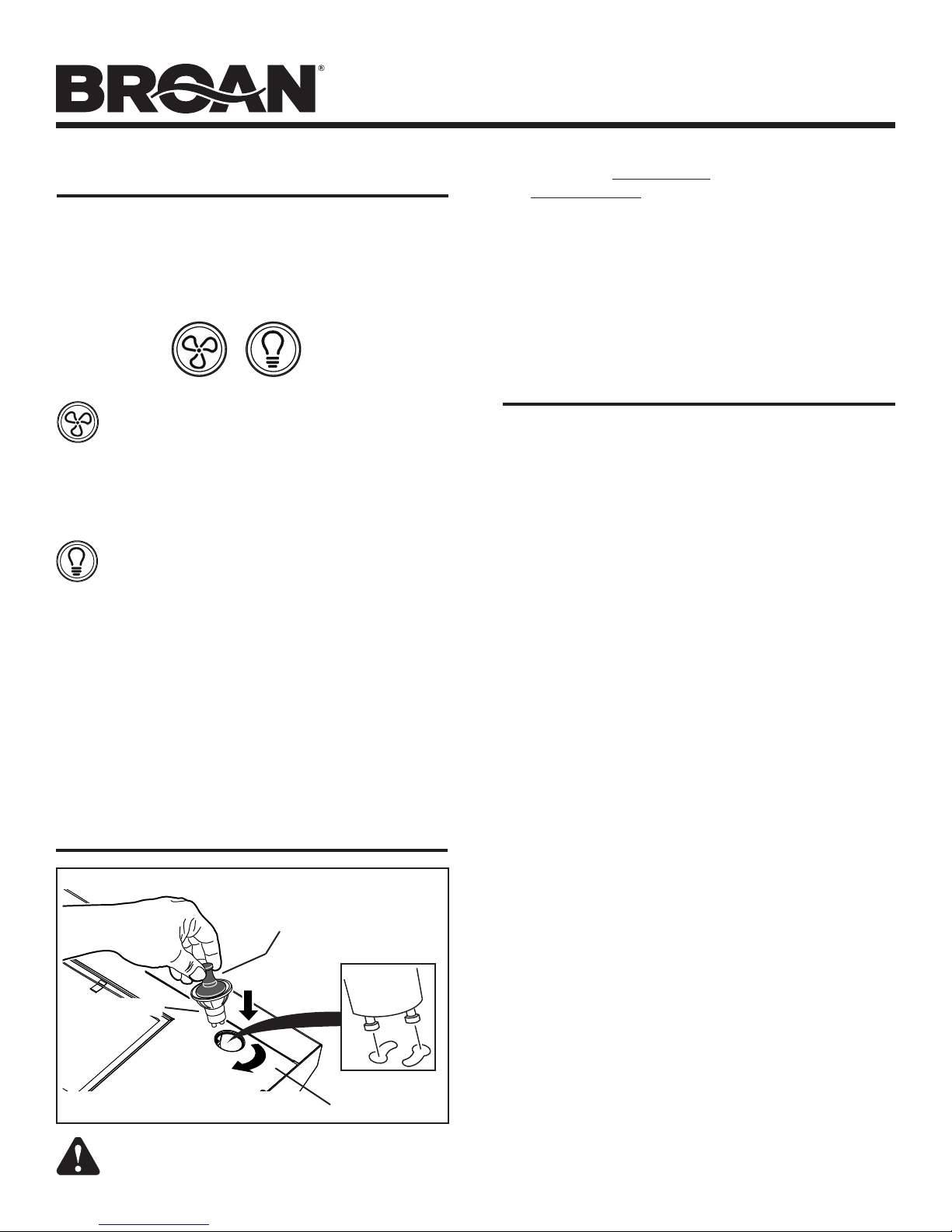
LIGHT BULB REPLACEMENT
SUCTION
CUP TOOL
(1)
HALOGEN
BULB
(2)
ROTATE
CLOCKWISE
CAUTION: Bulbs may be hot. Refer to bulb
packaging for further information.
PUSH IN
LIGHT PANEL
Use 120 V, 35 W, Halogen Bulbs - MR16 with GU10 base.
The Suction Cup Tool (included with hood) can be used to install
and remove light bulbs. Press suction cup tool on to bulb and
rotate counterclockwise to remove bulb or clockwise to install bulb.
Align pins on bulb with large diameter opening on socket, then
push bulb up into socket and rotate clockwise until firmly seated.
The position of the bulb socket (depth) is adjustable and may
require adjustment when:
a) certain brands of bulbs are difficult to install.
b) the bulb protrudes too far below the light panel.
See Step 25 for bracket adjustment detail.
CLEANING & MAINTENANCE
Proper maintenance of the Range Hood will assure proper
performance of the unit.
Motor
The motor is permanently lubricated and never needs oiling. If
the motor bearings make excessive or unusual noise, replace
the motor with the exact service motor. The impeller should also
be replaced.
Grease Filter
The grease filter should be cleaned frequently. Use a warm
dishwashing detergent solution. Grease filter is dishwasher safe.
Clean all-metal filters in the dishwasher using a non-phosphate
detergent. Discoloration of the filter may occur if using phosphate
detergents, or as a result of local water conditions - but this will
not affect filter performance. This discoloration is not covered by
the warranty.
See “INSTALL FILTERS” section for removal and installation
instructions.
Non-ducted Recirculation Filter
The non-ducted recirculation filter should be changed every 3-6
months. Replace more often if your cooking style generates extra
grease, such as frying and wok cooking.
Stainless Steel Cleaning
DO:
• Regularly wash with clean cloth or rag soaked with warm
water and mild soap or liquid dish detergent.
• Alwayscleaninthedirectionoforiginalpolishlines.
• Alwaysrinsewellwithclearwater(2or3times)aftercleaning.
Wipe dry completely.
• You may also use a specialized household stainless steel
cleaner.
DON’T:
• Useanysteelorstainlesssteelwooloranyotherscrapersto
remove stubborn dirt.
• Useanyharshorabrasivecleansers.
• Allowdirttoaccumulate.
• Letplasterdustoranyotherconstructionresiduesreachthe
hood. During construction/renovation, cover the range hood
to make sure no dust sticks to the stainless steel surface.
Avoid: When choosing a detergent
• Anycleanersthatcontainbleachwillattackstainlesssteel.
• Any products containing chloride, fluoride, iodide, bromide
will deteriorate surfaces rapidly.
• Anycombustibleproductsusedforcleaning,suchasacetone,
alcohol, ether, benzol, etc. are highly explosive and should
never be used close to a range.
Page 3
CBD3 SERIES
Page 3
INSTALL DUCTWORK
(Ducted Hoods Only)
ROOF CAP
SOFFIT
CABINET
HOODHOOD
18" - 24" ABOVE
COOKING SURFACE
1 Determine whether hood will discharge vertically (3¼” x
10” or 7” Round), or horizontally (3¼” x 10” only).
2 Decide where the ductwork will run between the hood
and the outside.
3¼" X 10" or
7" ROUND DUCT
(For vertical
discharge)
HOUSE WIRING
(Top or Back of hood)
WALL CAP
3¼" X 10" DUCT
(For horizontal discharge)
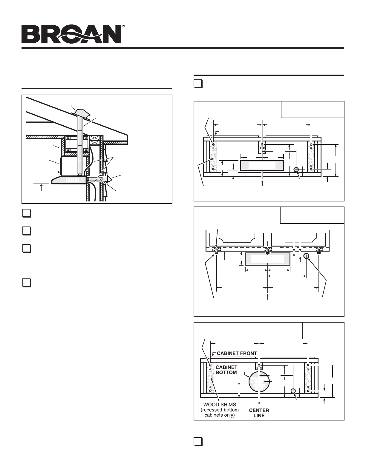
PREPARE HOOD LOCATION
5 Use the proper diagram below for placement of ductwork
and electrical cutout in cabinet or wall. For a non-ducted
installation, DO NOT cut a duct access hole.
3¼” X 10”
HOOD MOUNTING SCREWS (5)
15
/
13
"(30" hood)
16
13
CABINET FRONT
CABINET
BOTTOM
*
5¼"
VERTICAL DUCT
5"
ACCESS HOLE
1¼"
WOOD SHIMS
(recessed-bottom
cabinets only)
CENTER
LINE
WOOD SHIMS
(recessed-bottom
cabinets only)
CABINET FRONT
VERTICAL DUCTING
15
/
"(30" hood)
16
1
/
7
"
2
5¼"
1
/
9
"
2
2"
ELECTRICAL
ACCESS HOLE
(in cabinet bottom)
3¼” X 10”
HORIZONTAL DUCTING
3
/4"
1
/8"
1
/
10
1
/
"
2
1
"
2
3 Choose a straight, short duct run to allow the hood to
perform most efficiently. Long duct runs, elbows and
transitions will reduce the performance of the hood. Use
as few of them as possible. Larger ductwork may be
required for best performance with longer duct runs.
4 Install wall cap or roof cap. Connect metal ductwork to
cap and work back towards the hood location. Use duct
tape to seal the joints between ductwork sections.
HORIZONTAL DUCT
CABINET
BOTTOM
15
/
13
3¾"
"(30" hood)
16
ACCESS HOLE
1
/
"
5
4
HOOD
MOUNTING
SCREWS (5)
CENTER
LINE
HOOD MOUNTING SCREWS (5)
15
/
13
"(30" hood)
16
8" DIA.
HOLE
5"
7-IN. ROUND
7-IN. ROUND
DUCT
DUCT
ACCESS
ACCESS
HOLE
HOLE
13
*
*
1
/
5
"
4
71/2"
15
/
"(30" hood)
16
13
ELECTRICAL
ACCESS HOLE
15
/
"(30" hood)
16
71/2"
91/2"
21/8"
ELECTRICAL
ACCESS HOLE
(in cabinet bottom)
(in wall)
7-IN. ROUND
DUCTING
1
1
/2"
10
1
/2"
Note the extra wood shim and mounting screw near the
*
cabinet front, on the cabinet center line.
6 Install 4 Hood Mounting Screws into shims/cabinet
according to proper diagram above. Do not tighten
completely. Do not install middle screw until Step 20.
Page 4
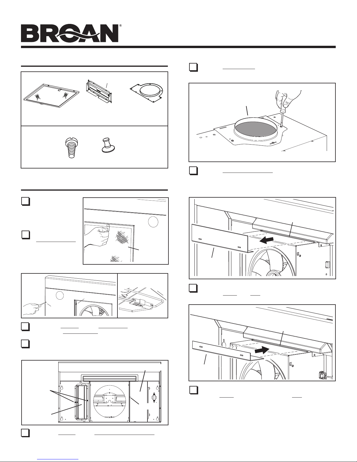
CONTENTS
(1) GREASE
FILTER
(1) PARTS BAG** CONTAINING:
(5) #10 X 5/8”
RD. HD.
MOUNTING
SCREWS
* FIND INSIDE
OF HOOD
(1) 3¼” X 10”
DAMPER / DUCT
CONNECTOR*
(1) BULB SUCTION
** FIND PARTS BAG
INSIDE OF BOTTOM PANEL.
(1) 7” ROUND
CONNECTOR
CUP TOOL
CBD3 SERIES
Page 4
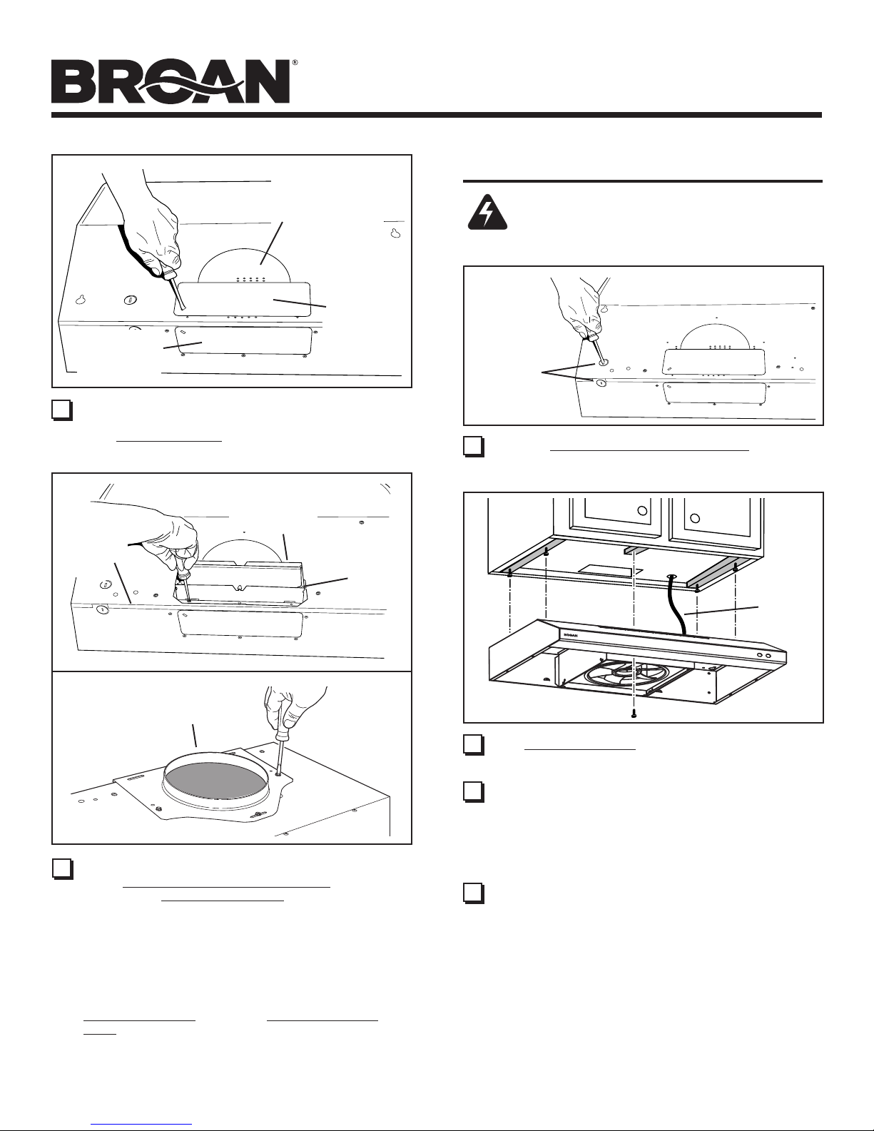
12 Remove Wiring Cover from inside of hood Set cover and
screw aside.
7” ROUND
DUCT
PLATE
DUCT
13 Remove 7” Round Duct Plate from top/back of hood.
PREPARE THE HOOD
7 Remove all
protective polyfilm
from the hood
(stainless steel
hoods only).
8 Remove the
Aluminum Filter
from the hood by
pulling the tab
down and lifting
filter out.
(4)
9 Remove 8 Screws holding Bottom Pan to hood.
Disconnect Light Harness.
10 Remove parts bag included with the hood. (Parts bag is
inside the hood.)
(4)
(2)
LIFT
OUT
ç
(1)
PULL
DOWN
ç
ALUMINUM
FILTER
ç
FOR NON-DUCTED INSTALLATIONS - Skip to
“INSTALL THE HOOD”.
SLOT
BAFFLE
14 DUCTED INSTALLATION ONLY:
Remove Baffle from Slot above air box.
ç
SLOT
SCREWS
DAMPER /
DUCT
CONNECTOR
11
Remove 2 Screws holding Damper / Duct Connector to
hood. Remove damper/duct connector from inside the hood.
WIRING COVER
SCREW
BAFFLE
15 DUCTED INSTALLATION ONLY:
Rotate Baffle and insert long side into Slot above air
box. Baffle is inserted properly when you feel a positive
stop.
Page 5
CBD3 SERIES
Page 5
7” ROUND
KNOCKOUT
PLATE (also
remove 3¼” x 10”
vertical plate)
KNOCKOUT
3¼” X 10”
HORIZONTAL
KNOCKOUT
PLATE
16 DUCTED INSTALLATION ONLY:
Remove 3¼” x 10 vertical, 3¼” x 10” horizontal, or 7-inch
round knockout plate(s) as appropriate for your ducting
method.
3¼” X 10”
DAMPER /
DUCT
CONNECTOR
TOP/BACK
EDGE OF
HOOD
3¼” X 10”
VERTICAL
PLATE
DAMPER
FLAP
PIVOT
INSTALL THE HOOD
WARNING
To reduce the risk of electrical shock, switch power off
at service panel. Lock or tag service panel to prevent
power from being switched on accidentally.
ELECTRICAL
POWER
CABLE
KNOCKOUT
18 Remove Electrical Power Cable Knockout from top or
back of hood.
HOUSE
POWER
CABLE
7” ROUND
DUCT
PLATE
17 DUCTED INSTALLATION ONLY:
Attach 3¼” x 10” Damper/Duct Connector (if using 3¼”
x 10” duct) or 7” Round Duct Plate (if using 7-inch round
duct) over the knockout opening.
Notes:
To accomodate off-center ductwork, the 3¼” x 10”
damper/duct connector or the 7” round duct plate can be
installed up to ½” on either side of the hood center.
Install the 3¼” x 10” Damper/Duct Connector with the
Damper Flap Pivot nearest the Top/Back Edge of
Hood.
For 7” round duct, install a 7” round damper (#97010792 purchase separately).
19 Run House Power Cable between service panel and hood
location. Attach power cable to hood using appropriate clamp
(not included).
20 Hang hood from (4) mounting screws driven part-way into
cabinet locations (shown in illustrations under “PREPARE
HOOD LOCATION”). Mounting screws are included in parts
bag. Slide hood back towards wall until mounting screw
heads are engaged in narrow end of keyhole slots in top of
hood. Tighten screws securely. Add 5th mounting screw in
center hole in hood and tighten securely.
21 DUCTED INSTALLATION ONLY:
Connect ductwork to hood and use duct tape to make joints
secure and air-tight. Make sure the damper / duct connector
enters the ductwork and that the damper opens and closes
freely.
Page 6

CBD3 SERIES
Page 6
CONNECT THE WIRING
GROUND
SCREW
HOUSE
POWER CABLE
22 Connect House Power Cable to range hood wiring -
BLACK to BLACK, WHITE to WHITE, and GREEN or
BARE WIRE to Ground Screw.
23 Replace wiring cover.
24 Re-connect lamp wire harness and re-attach bottom panel
with (8) screws as shown in Step 9.
INSTALL LIGHT BULBS
LAMP SOCKET
BRACKET
SCREWS
To change the depth of bulb sockets:
- Remove bottom panel (See Step 9).
- Disconnect light harness.
- Loosen 2 Screws holding Lamp Socket Bracket to
Light Panel.
- Adjust socket/bracket to desired depth.
- Re-tighten screws securely.
- Re-attach light harness and replace bottom panel.
26 DUCTED INSTALLATION ONLY:
Re-install aluminum filters removed in Step 8.
NON-DUCTED INSTALLATION ONLY:
Purchase a non-ducted filter (Model BPQTF) from your
local distributor or retailer. Attach the non-ducted filter following instructions packed with the non-ducted filter.
SUCTION
CUP TOOL
(1)
HALOGEN
BULB
(2)
ROTATE
CLOCKWISE
CAUTION: Bulbs may be hot. Always allow bulbs
to cool before removing them.
25 Install (2) Halogen Bulbs. Use 120 V, 35 W, shielded
halogen bulbs - MR16 with GU10 base.
NOTE: Suction Cup Tool (included with hood) can be
used to install and remove light bulbs.
Align pins on bulb with large diameter opening on socket,
then push bulb up into socket and rotate clockwise until
firmly seated.
The position of the bulb socket (depth) is adjustable and
may require adjustment when:
a) certain brands of bulbs are difficult to install.
b) the bulb protrudes too far below the light panel.
PUSH IN
LIGHT PANEL
Page 7

SERVICE PARTS
CBD3 SERIES
Page 7
13
3
5
6
14
2
7
8
15
18
4
11
10
9
16
17
1
12
2
KEY
NO. DESCRIPTION PART NO.
1 BOTTOM PANEL, WHITE, 30” 97018651
BOTTOM PANEL, BLACK, 30” 97018652
BOTTOM PANEL, STAINLESS STEEL, 30” 97018653
BOTTOM PANEL, WHITE, 36” 98010876
BOTTOM PANEL, BLACK, 36” 98010877
2 SCREW PACKAGE FOR BOTTOM PANEL & AIR DUCT R602534
#8-18 X 3/8 (10 req.) (2 screws in a bag)
3 LAMP WIRE HARNESS 97018656
4 WIRE HARNESS 99271466
5 LIGHT BRACKET HARDWARE BAG 97018665
6 BAFFLE 99111539
7 AIR CHUTE 99111538
AIR CHUTE ASSEMBLY (includes Key Nos. 6, 7 and hardware) 97018660
8 CONTROL ASSEMBLY, WHITE 97019322
CONTROL ASSEMBLY, BLACK 97019323
CONTROL ASSEMBLY, STAINLESS STEEL 97019324
9 FAN BLADE (INCLUDES HAIRPIN CLIP) R531076
10 HAIRPIN CLIP R99420635
11 PARTS BAG ASSEMBLY 97018623
12 FILTER ALUMINUM R610092
13 7” ROUND DUCT PLATE (includes mounting hardware) R680508
14 3-1/4” X 10” DAMPER ASSEMBLY (includes mounting hardware) R740014
15 MOTOR 99080666
16 CABLE CLIP, WIRE HARNESS 99680044
17 WIRING COVER 98009816
18 TRANSFORMER 99271478
* 7-IN. ROUND DAMPER 97010792
* NON-DUCTED FILTER 99010317
* BULB, 120V, 35W, MR16 GU10 BASE HALOGEN (2 req.) 99526798
* Not illustrated. Purchase separately.
Order replacement parts by PART NO. - not by KEY NO.
Page 8

CBD3 SERIES
Page 8
WARRANTY
Limited Warranty
Warranty Period and Exclusions: Broan-NuTone LLC (the “Company”) warrants to the original consumer purchaser of its product
(“you”) that the product (the “Product”) will be free from material defects in the Product or its workmanship for a period of one (1) year
from the date of original purchase. The warranty on the light bulbs provided with the Product is one (1) year and does not cover lamp/
bulb breakage.
The limited warranty period for any replacement parts provided by the Company and for any Products repaired or replaced under this
limited warranty shall be the remainder of the original warranty period.
This warranty does not cover fluorescent lamp starters, tubes, halogen and incandescent bulbs, fuses, filters, ducts, roof caps, wall caps
and other accessories for ducting that may be purchased separately and installed with the Product. This warranty also does not cover
(a)normal maintenance and service, (b)normal wear and tear, (c)any Products or parts which have been subject to misuse, abuse,
abnormal usage, negligence, accident, improper or insufficient maintenance, storage or repair (other than repair by the Company),
(d)damage caused by faulty installation, or installation or use contrary to recommendations or instructions, (e)any Product that has
been moved from its original point of installation, (f)damage caused by environmental or natural elements, (g)damage in transit,
(h)natural wear of finish, (i)Products in commercial or nonresidential use, or (j)damage caused by fire, flood or other act of God. This
warranty covers only Products sold to original consumers in the United States by the Company or U.S. distributors authorized by the
Company.
This warranty supersedes all prior warranties and is not transferable from the original consumer purchaser.
No Other Warranties: This Limited Warranty contains the Company’s sole obligation and your sole remedy for defective products.
The foregoing warranties are exclusive and in lieu of any other warranties, express or implied. THE COMPANY DISCLAIMS AND
EXCLUDES ALL OTHER EXPRESS WARRANTIES, AND DISCLAIMS AND EXCLUDES ALL WARRANTIES IMPLIED BY LAW,
INCLUDING WITHOUT LIMITATION THOSE OF MERCHANTABILITY AND FITNESS FOR A PARTICULAR PURPOSE. To the
extent that applicable law prohibits the exclusion of implied warranties, the duration of any applicable implied warranty is limited to the
period specified for the express warranty above. Some states do not allow limitations on how long an implied warranty lasts, so the
above limitation may not apply to you. Any oral or written description of the Product is for the sole purpose of identifying it and shall not
be construed as an express warranty.
Whenever possible, each provision of this Limited Warranty shall be interpreted in such manner as to be effective and valid under
applicable law, but if any provision is held to be prohibited or invalid, such provision shall be ineffective only to the extent of such
prohibition or invalidity, without invalidating the remainder of such provision or the other remaining provisions of the Limited Warranty.
Remedy: During the applicable limited warranty period, the Company will, at its option, provide replacement parts for, or repair or
replace, without charge, any Product or part thereof, to the extent the Company finds it to be covered by and in breach of this limited
warranty under normal use and service. The Company will ship the repaired or replaced Product or replacement parts to you at no
charge. You are responsible for all costs for removal, reinstallation and shipping, insurance or other freight charges incurred in the
shipment of the Product or part to the Company. If you must send the Product or part to the Company, as instructed by the Company,
you must properly pack the Product or part—the Company is not responsible for damage in transit. The Company reserves the right to
utilize reconditioned, refurbished, repaired or remanufactured Products or parts in the warranty repair or replacement process. Such
Products and parts will be comparable in function and performance to an original Product or part and warranted for the remainder of
the original warranty period.
Exclusion of Damages: THE COMPANY’S OBLIGATION TO PROVIDE REPLACEMENT PARTS, OR REPAIR OR REPLACE, AT
THE COMPANY’S OPTION, SHALL BE YOUR SOLE AND EXCLUSIVE REMEDY UNDER THIS LIMITED WARRANTY AND THE
COMPANY’S SOLE AND EXCLUSIVE OBLIGATION. THE COMPANY SHALL NOT BE LIABLE FOR INCIDENTAL, INDIRECT,
CONSEQUENTIAL OR SPECIAL DAMAGES ARISING OUT OF OR IN CONNECTION WITH THE PRODUCT, ITS USE OR
PERFORMANCE.
Some states do not allow the exclusion or limitation of incidental or consequential damages, so the above limitation or exclusion may
not apply to you. This warranty gives you specific legal rights, and you may also have other rights, which vary from state to state.
This warranty covers only replacement or repair of defective Products or parts thereof at the Company’s main facility and does not
include the cost of field service travel and living expenses.
Any assistance the Company provides to or procures for you outside the terms, limitations or exclusions of this limited warranty will not
constitute a waiver of such terms, limitations or exclusions, nor will such assistance extend or revive the warranty.
The Company will not reimburse you for any expenses incurred by you in repairing or replacing any defective Product, except for those
incurred with the Company’s prior written permission.
How to Obtain Warranty Service: To qualify for warranty service, you must (a)notify the Company at the address or telephone
number stated below within seven (7)days of discovering the covered defect, (b)give the model number and part identification and
(c)describe the nature of any defect in the Product or part. At the time of requesting warranty service, you must present evidence of
the original purchase date. If you cannot provide a copy of the original written limited warranty, then the terms of the Company’s most
current written limited warranty for your particular product will control.The most current limited written warranties for the Company’s
products can be found at www.broan.com .
Broan-NuTone LLC 926 West State Street, Hartford, WI 53027 www.broan.com 800-637-1453
99045076C
Page 9

SERIE CBD3
Página 9
Campanas
Registre su producto en el
sitio web www.broan.com
Serie CBD3
LEA Y CONSERVE ESTAS INSTRUCCIONES
SOLAMENTE PARA COCINAR EN CASA
ADVERTENCIA
PARA REDUCIR EL RIESGO DE INCENDIO, DESCARGA ELÉCTRICA
O LESIONES CORPORALES, OBSERVE LO SIGUIENTE:
1. Use la unidad sólo de la manera indicada por el fabricante. Si tiene
preguntas, comuníquese con el fabricante a la dirección o al número
telefónico que se incluye en la garantía.
2. Antes de dar servicio a la unidad o de limpiarla, interrumpa el
suministro eléctrico en el panel de servicio y bloquee los medios de
desconexión del servicio para evitar que la electricidad se reanude
accidentalmente. Cuando no sea posible bloquear los medios de
desconexión del servicio, fije firmemente una señal de advertencia
(como una etiqueta) en un lugar visible del panel de servicio.
3. Una o más personas calificadas deben realizar el trabajo de
instalación y el cableado eléctrico siguiendo todos los códigos y
normas correspondientes, incluidos los códigos y las normas de
construcción específicos para incendios.
4. Se necesita suficiente aire para que se lleve a cabo una combustión
y una extracción adecuadas de los gases a través del tubo de
humos (chimenea) del equipo quemador de combustible, con el fin
de evitar el contratiro. Siga las directrices y las normas de seguridad
del fabricante del equipo de calefacción, como las publicadas por
la Asociación Nacional de Protección contra Incendios (National
Fire Protection Association, NFPA), y la Sociedad Americana de
Ingenieros en Calefacción, Refrigeración y Aire Acondicionado
(American Society of Heating, Refrigeration and Air Conditioning
Engineers, ASHRAE), y las autoridades de los códigos locales.
5. Este producto podría tener bordes afilados. Trabaje con cuidado
para evitar cortes y abrasiones durante la instalación y la limpieza.
6. Al cortar o perforar a través de la pared o del techo, tenga cuidado
de no dañar el cableado eléctrico ni otros servicios ocultos.
7. Los ventiladores en conductos siempre deben ventearse hacia el
exterior.
8. Utilice únicamente conductos metálicos.
9. No use este ventilador junto con ningún dispositivo de control de
velocidad de estado sólido.
10. Como alternativa, se puede instalar este producto con el juego de
cable de alimentación aprobado por UL y diseñado para el producto,
siguiendo las instrucciones incluidas con el cable.
11. Esta unidad debe estar conectada a tierra.
PARA REDUCIR EL RIESGO DE INCENDIO PROVOCADO POR
GRASA PRESENTE EN LA ESTUFA:
1. Nunca deje desatendidas las unidades de la superficie cuando
estén en ajustes altos de calor. Los alimentos en ebullición provocan
derrames grasosos y con humo que se pueden incendiar. Caliente
el aceite lentamente en ajustes de calor bajo o medio.
2. Siempre ENCIENDA la campana cuando esté cocinando a altas
temperaturas o flamee alimentos (por ejemplo crepas Suzette,
cerezas Jubilee, bistec con pimienta flameado).
3. Limpie frecuentemente los ventiladores. No permita la acumulación
de grasa en el ventilador ni en el filtro.
4. Use una cacerola del tamaño adecuado. Siempre use utensilios
de cocina que sean apropiados para el tamaño del elemento dela
superficie
.
ADVERTENCIA
PARA REDUCIR EL RIESGO DE LESIONES A LAS PERSONAS EN CASO DE
UN INCENDIO PRODUCIDO POR GRASA EN UNA ESTUFA, OBSERVE
LO SIGUIENTE*:
1. APAGUE LAS LLAMAS con una tapa de ajuste exacto, una charola para
galletas o una bandeja de metal, y después apague el quemador. PROCEDA
CON CUIDADO PARA EVITAR QUEMADURAS. Si las llamas no se apagan
inmediatamente, EVACUE EL ÁREA Y LLAME A LOS BOMBEROS.
2. NUNCA LEVANTE UNA CACEROLA INCENDIADA porque podría sufrir
quemaduras o propagar el incendio.
3. NO USE AGUA, incluidos trapos o toallas de cocina mojados; puede
producirse una explosión violenta de vapor.
4. Use un extintor SÓLO si:
A. Sabe que tiene un extintor clase ABC, y ya sabe cómo usarlo.
B. El incendio es pequeño y está confinado al área en la que se inició.
C. Se está llamando al Departamento de Bomberos.
D. Puede combatir el incendio teniendo la espalda orientada hacia una salida.
*Basado en “Consejos útiles de seguridad en incendios en la cocina” (“Kitchen
Fire Safety Tips”), publicado por NFPA.
PRECAUCIÓN
1. Sólo debe usarse bajo techo.
2. Sólo para usarse como medio de ventilación general. No debe
usarse para la extracción de materiales o vapores peligrosos o
explosivos.
3. Para evitar daños a los cojinetes del motor y rotores ruidosos o
desbalanceados, mantenga la unidad eléctrica al resguardo de
rociados de yeso, polvo de construcción, etc.
4. No use equipo para cocinar mayor de 60,000 BTU/hr.
5. Este motor de campana tiene una protección contra sobrecargas térmicas
que automáticamente apagará el motor en caso de sobrecalentamiento.
El motor reanudará su funcionamiento cuando se enfríe. Si el motor
continúa apagándose y encendiéndose, solicite servicio para la campana.
6. Una altura máxima de 24” por encima de la superficie de cocción se recomienda para limpiar mejor las impurezas al cocinar. La parte inferior
de la campana no debe ser inferior a 18” por encima de la superficie de
cocción.
7. Lea la etiqueta de especificaciones que tiene el producto para ver
información y requisitos adicionales.
NOTA Si la campana se va a instalar en un sistema sin conductos:
Compre un filtro sin conductos (Modelo BPQTF) con su
distribuidor o tienda minorista local.
Aviso al instalador: Deje este manual
con el dueño de la casa.Aviso al dueño
de la casa: En la página 10 encontrará
lasinstrucciones de limpieza,
mantenimiento y funcionamiento.
Page 10

FUNCIONAMIENTO
SERIE CBD3
Página 10
ENCIENDA siempre la campana antes de comenzar a cocinar, con el fin de
establecer un flujo de aire en la cocina. Después de apagar la estufa, deje
que la campana funcione durante unos cuantos minutos para despejar el aire.
Esta campana está equipada con lo último en tecnología táctil capacitiva. Los
botones no se mueven, pero son sensibles al tacto. Cuando un contacto es
interpretado, el control emitirá un sonido.
VENTILADOR
1. Toque el botón del ventilador para encender el ventilador a
baja velocidad.
2. Toque de nuevo el botón del ventilador para velocidad máxima
y apagado.
El anillo de luz alrededor del botón se iluminará cuando el
ventilador este encedido - un tenue brillo para velocidad baja y un
brillo mas fuerte para alta velocidad.
LUZ
1. Toque el botón de luz para encender la luz en el ajuste oscuro.
2. Pulse el botón de nuevo para luz brillante o apagada.
El anillo de luz alrededor del botón se iluminará cuando la luz
esté encendida - un tenue brillo para luz baja y brillo mas fuerte
para luz brillante.
LIMPIEZA DEL FILTRO
El anillo de ventilador del ventilador destellará cuando sea tiempo de limpiar
o reemplazar el filtro, basado en su patrón individual.
Para poner a cero el indicador del filtro recordatorio de limpieza, presione y
mantenga presionado el botón del ventilador durante tres segundos.
REEMPLAZO DE LAS BOMBILLAS
HERRAMIENTA
DE VENTOSA
(1)
EMPUJAR
HACIA
BOMBILLA DE
HALÓGENO
(2)
(2)
GIRAR EN SENTIDO
GIRAR EN SENTIDO
DE LAS AGUJAS
DE LAS AGUJAS
DEL RELOJ
DEL RELOJ
PRECAUCIÓN: Las bombillas podrían estar
calientes. Consulte la información adicional en los
paquetes de las bombillas.
Utilice bombillas de halógeno de 120 V, 35 W (MR16 con base GU10).
La herramienta de ventosa (incluida con la campana) sirve para instalar
y quitar bombillas. Prensa herramienta de ventosa a la bombilla y girar a la
izquierda para quitar la bombilla o hacia la derecha para instalar la bombilla.
Alinee las clavijas de la bombilla con la abertura de diámetro grande en el
receptáculo, empuje la bombilla para arriba en el zócalo y luego gire hacia la
derecha hasta que esté firmemente asentada.
La posición del receptáculo de la bombilla (profundidad) es ajustable, y podría
necesitar ajuste cuando:
a) Ciertas marcas de bombillas sean difíciles de instalar.
b) La bombilla sobresalga demasiado por debajo del panel de la bombilla.
Vea el paso 25 para el detalle soporte de ajuste.
ADENTRO
PANEL DE
ILUMINACIÓN
LIMPIEZA Y MANTENIMIENTO
El mantenimiento correcto de la campana de la estufa asegurará el
funcionamiento adecuado de la unidad.
Motor
El motor está permanentemente lubricado y nunca necesitará ponerle aceite.
Si los cojinetes del motor están haciendo ruido excesivo o inusual, reemplace
el motor con el motor de servicio exacto. También debe reemplazar el impulsor.
Filtro de grasa
El filtro de grasa se debe limpiar con frecuencia. Utilice una solución tibia de
detergente para platos. El filtro de grasa se puede lavar en lavaplatos. Limpie
los filtros completamente metálicos en la lavaplatos con un detergente sin
fosfatos. El filtro se puede decolorar si se utilizan detergentes con fosfato o como
resultado de la condición del agua local, pero esto no afectará el desempeño
del filtro. Esta decoloración no está cubierta por la garantía.
Consulte la sección “INSTALACIÓN DE LOS FILTROS” para ver las
instrucciones de instalación y desmontaje.
Filtro de recirculación para sistemas sin conductos
El filtro de recirculación para sistemas sin conductos se debe cambiar cada
3-6 meses. Cámbielo con más frecuencia si su estilo de cocinar genera más
grasa, como freír los alimentos o cocinar en un wok. Consulte las instrucciones
para quitar e instalar en el paso 15 de la página 18.
Limpieza del acero inoxidable
COSAS QUE PUEDE HACER:
• Regularmente,laveconunatelaotrapolimpioremojadoconaguatibiay
jabón o detergente líquido para platos.
• Siemprelimpieenladireccióndelaslíneasoriginalesdepulido.
• Siempre enjuague bien con agua limpia (2 o 3 veces) después dela
limpieza. Deje totalmente seco.
• También puede usar un limpiador casero especializado para acero
inoxidable.
COSAS QUE NO DEBE HACER:
• Usarlanadeacerooaceroinoxidablenialgúnotrotipoderaspadorpara
quitar mugre difícil de sacar.
• Usarlimpiadoresfuertesniabrasivos.
• Dejarqueseacumulelamugre.
• Dejar que el polvo forme plastas ni que quede en la campana algún
otro residuo de la construcción. Durante la construcción o la renovación,
cubra la campana para estar seguro de que el polvo no se pegue a la
superficie de acero inoxidable.
Evite: Al elegir un detergente
• Todo limpiador que contenga blanqueador, pues atacará al acero
inoxidable.
• Productos que contengan cloruro, fluoruro, yoduro, bromuro, pues
deteriorarán las superficies rápidamente.
• Todo producto combustible utilizado para la limpieza, como acetona,
alcohol, éter, benzol, etc., pues son altamente explosivos y nunca se
deben usar cerca de una estufa.
Page 11

SERIE CBD3
Página 11
INSTALE EL SISTEMA
DECONDUCTOS (Sólo campanas
para sistemas con conductos)
TAPA DE TECHO
PLAFÓN
GABINETE
CAMPANACAMPANA
DE 18 a 24 PULG.
(45.7 a 61 CM) POR ENCIMA DE
LA SUPERFICIE DE COCINADO
1 Determine si la descarga de la campana va a ser vertical
(conducto de 3¼ x 10 pulg. [8.3 x 25.4 cm] o redondo
de 7 pulg. [17.8 cm]) u horizontal (sólo conducto de
3¼ x 10 pulg. [8.3 x 25.4 cm]).
2 Decida dónde instalará el conducto entre la campana y
el exterior.
3 Elija un conducto recto y corto para permitir que la
campana funcione más eficientemente. Los tramos
largos de conductos, codos y transiciones reducirán
el desempeño de la campana. Use tan pocos de
ellos como sea posible. Es posible que se requieran
conductos más grandes para un mejor funcionamiento
con tramos más largos de conductos.
4 Instale la tapa para pared o para techo. Conecte un
conducto metálico en la tapa y trabaje hacia atrás,
hacia la ubicación de la campana. Use cinta para
conductos para sellar las uniones entre las secciones
deconductos.
CONDUCTO DE
3¼ x 10 pulg. (8.3 x 25.4 cm) o
CONDUCTO REDONDO
de 7 pulg. (17.8 cm)
(para descarga vertical)
CABLEADO ELÉCTRICO
DE LA CASA
(parte superior o
posterior de la campana)
TAPA DE PARED
CONDUCTO DE
3¼ x 10 pulg.
(8.3 x 25.4 cm)
(para descarga horizontal)
PREPARE EL LUGAR DONDE SE
VA A INSTALAR LA CAMPANA
TORNILLOS DE MONTAJE
DE LA CAMPANA (5)
13-15/16 pulg. (35.4 cm)
(campana de 30 pulg./76.2 cm)
FRENTE DEL GABINETE
PARTE INFERIOR
DEL GABINETE
5 pulg.
(12.7 cm)
1 ¼ pulg.
(3.2 cm)
CUÑAS DE MADERA
(sólo gabinetes
de parte inferior empotrada)
CUÑAS DE MADERA
(sólo gabinetes de parte
inferior empotrada)
3¾ pulg.
(9.5 cm)
PARTE
INFERIOR
DEL GABINETE
15
/
13
pulg. (35.4 cm)
16
(campana de 30 pulg./76.2 cm)
TORNILLOS DE
MONTAJE DE
LA CAMPANA (5)
TORNILLOS DE MONTAJE
DE LA CAMPANA (5)
CUÑAS DE MADERA
parte inferior empotrada)
13-15/16 pulg. (35.4 cm)
(campana de 30 pulg./76.2 cm)
FRENTE DEL GABINETE
8 pulg. (20.3 cm)
PARTE INFERIOR
DEL GABINETE
(12.7 cm)
(sólo gabinetes de
Orificio de
DE DIÁM.
5 pulg.
13-15/16 pulg. (35.4 cm)
(campana de 30 pulg./76.2 cm)
7 ½ pulg.
(19.1 cm)
5¼ pulg.
(13.3 cm)
ORIFICIO DE ACCESO PARA
CONDUCTO VERTICAL
*
5¼ pulg.
(13.3 cm)
LÍNEA
CENTRAL
PARA CABLES ELÉCTRICOS
(en la parte inferior del gabinete)
FRENTE DEL
GABINETE
ORIFICIO DE ACCESO PARA
CONDUCTO HORIZONTAL
5 ¼ pulg.
(13.3 cm)
*
5 ¼ pulg.
(13.3 cm)
7 ½ pulg. (19.1 cm)
13
(campana de 30 pulg./76.2 cm)
LÍNEA
CENTRAL
13-15/16 pulg. (35.4 cm)
(campana de 30 pulg./76.2 cm)
*
7 ½ pulg.
(19.1 cm)
ORIFICIO DE
ORIFICIO DE
ACCESO
ACCESO
PARA CONDUCTO
PARA CONDUCTO
REDONDO DE 7 pulg.
REDONDO DE 7 pulg.
(17.8 cm)
(17.8 cm)
LÍNEA
CENTRAL
9 ½ pulg.
(24.1 cm)
PARA CABLES ELÉCTRICOS
(en la parte inferior del gabinete)
CONDUCTO VERTICAL DE
3¼ X 10 PULG. (8.3 X 25.4 CM)
10 ½ pulg.
1 ½ pulg.
(3.8 cm)
(26.7 cm)
9 ½ pulg
2 pulg
(24.1 cm)
(5.1 cm)
ORIFICIO DE ACCESO
CONDUCTO HORIZONTAL DE
3¼ X 10 PULG. (8.3 X 25.4 CM)
3
/4 pulg.
(1.9 cm)
1
/8 pulg.
(0.32 cm)
15
/
pulg. (35.4 cm)
16
ORIFICIO DE
ACCESO PARA
CABLES ELÉCTRICOS
(en la pared)
CONDUCTO REDONDO
DE 7 PULG. (17.8 CM)
2 pulg.
(5.1 cm)
ORIFICIO DE ACCESO
10 ½ pulg.
(26.7 cm)
1 ½ pulg.
(3.8 cm)
5 Guíese por el diagrama correspondiente (a continuación)
para colocar los conductos y hacer el corte exacto para
la conexión eléctrica en el gabinete o en la pared. Para
instalaciones en sistemas sin conductos, NO haga
ningún orificio de acceso para conducto.
* Observe la cuña de madera adicional y el tornillo de
montaje cerca del frente del gabinete, sobre la línea central
del gabinete.
6 Instale 4 tornillos de montaje de la campana en
las calzas/gabinete, de acuerdo con el diagrama
correspondiente. No apriete totalmente. No instale el
tornillo de en medio hasta el paso 20.
Page 12

CONTENIDO
SERIE CBD3
Página 12
* ENCUENTRA EN EL INTERIOR
DE LA CAMPANA.
(1) FILTRO
DE GRASA
(1)
CONECTOR
PARA REGULADOR/
CONDUCTO DE 3¼ X 10
PULG. (8.3 X 25.4 CM)*
PARA CONDUCTO
7 PULG. (17.8 CM)
(1)
CONECTOR
REDONDO DE
(1) BOLSA DE PIEZAS** QUE CONTIENE:
(5) TORNILLOS DE
MONTAJE DE CABEZA
REDONDA #10 X
5/8 PULG.
** ENCUENTRA LA BOLSA DE PIEZAS
AL INTERIOR DEL PANEL INFERIOR.
(1) HERRAMIENTA
DE VENTOSA PARA
LAS BOMBILLAS
PREPARE LA CAMPANA
7 Quite todo el forro
de plástico protector
de la campana
(únicamente
campanas de
aceroinoxidable).
8 Retire el filtro de
aluminio de la
campana jalando
la lengüeta hacia
abajo y levantando
elfiltro.
(2)
LEVANTAR
HACIA
FUERA
ç
ç
(1) JALAR
HACIA
ABAJO
FILTRO DE
ALUMINIO
12 Retire la cubierta de cables desde el interior de la cubierta
de la campana y el tornillo a un lado.
PLACA DEL
CONDUCTO
REDONDO
DE 7 PULG. (17.8 CM)
13 Retire la placa del conducto redondo de 7 pulg. (17.8 cm)
de la parte superior/trasera de la campana.
RANURA
DEFLECTOR
(4)
(4)
9 Quite los 8
tornillos
campana. Desconecte el
que sostienen el
arnés de las luces.
ç
recipiente inferior
ç
a la
10 Retire la bolsa de piezas incluida con la campana. (La bolsa
de piezas está dentro de la campana.)
CUBIERTA DE CABLES
TORNILLOS
CONECTOR DEL
REGULADOR
DE TIRO/
CONDUCTO
TORNILLO
11 Quite los 2 tornillos que sujetan el conector del regulador de
tiro/conducto a la campana. Quite el conector del regulador de
tiro/conducto del interior de la campana.
14 ÚNICAMENTE EN INSTALACIONES CON CONDUCTOS:
Retire el
DEFLECTOR
deflector
de la
ranura
arriba de la caja de aire.
RANURA
15 ÚNICAMENTE EN INSTALACIONES CON CONDUCTOS:
Gire el
deflector
e inserte el lado largo en la
ranura
arriba
de la caja de aire. El deflector se inserta adecuadamente
cuando siente un tope positivo.
Page 13

SERIE CBD3
Página 13
PLACA REDONDA DE
ORIFICIO CIEGO DE 7
PULG. (17.8 CM) (TAMBIÉN
DESMONTE LA PLACA
VERTICAL DE 3¼ X 10 PULG.
[8.3 X 25.4 CM])
PLACA HORIZONTAL
DE ORIFICIO CIEGO
DE 3¼ X 10 PULG.
PLACA VERTICAL
DE ORIFICIO CIEGO
DE 3¼ X 10 PULG.
(8.3 X 25.4 CM)
(8.3 X 25.4 CM)
16 ÚNICAMENTE EN INSTALACIONES CON CONDUCTOS:
Retire las placas de orificio ciego vertical de 3¼ x 10 pulg.
(8.3 x 25.4 cm), horizontal de 3¼ x 10 pulg. (8.3 x 25.4 cm),
o redonda de 7 pulg. (17.8 cm), según corresponda a su
método de conductos.
CONECTOR PARA
REGULADOR DE TIRO/
BORDE
SUPERIOR/
POSTERIOR DE
LA CAMPANA
CONDUCTO DE 3¼ X 10 PULG.
(8.3 X 25.4 CM)
PIVOTE DE LA
ALETA DEL
REGULADOR
DE TIRO
INSTALE LA CAMPANA
ADVERTENCIA
Para reducir el riesgo de una descarga eléctrica,
18 Quite el
desconecte el suministro eléctrico en el panel de
servicio. Bloquee el panel de servicio o póngale una
etiqueta de seguridad para evitar que alguien conecte
accidentalmente la energía eléctrica.
ORIFICIO
CIEGO DEL
CABLE
ELÉCTRICO
orificio ciego del cableado eléctrico
parte superior o trasera de la campana.
desde la
PLACA DEL CONDUCTO
REDONDO
DE 7 PULG. (17.8 CM)
17 ÚNICAMENTE EN INSTALACIONES CON CONDUCTOS:
Acople el conector del regulador de tiro/conducto
de 3¼ pulg. x 10 pulg. (8.3 x 25.4 cm) (si está usando
elconducto de 3¼ pulg. x 10 pulg. [8.3 x 25.4 cm]) o la
placa redonda de 7 pulg. (17.8 cm) (si está usando el
conducto redondo de 7pulg. [17.8 cm]) por la abertura del
orificio ciego.
Notas:
Para acomodar los conductos descentrados, el amortiguador/
conducto de 3¼” x 10” o la placa del conducto redondo de 7” se
pueden instalar hasta ½” a cada lado del centro de la campana.
Instale el conector del regulador de tiro/conducto de 3¼ x 10 pulg.
(8.3 x 25.4 cm) con el pivote de aleta del regulador más cercano
al borde superior/trasero de la campana.
Para el ducto redondo de 7”, instale un amortiguador redondo de 7”
(#97010792 - comprar por separado).
CABLE
ELÉCTRICO
DE LA CASA
19 Tienda el cable eléctrico de la casa entre el panel de servicio
y la campana. Conecte el cable eléctrico a la campana con la
abrazadera apropiada (no incluye).
20 Cuelgue la campana de los (4) orificios de montaje insertados
parcialmente en las posiciones del gabinete (mostrado en
las ilustraciones de “PREPARE EL LUGAR DONDE SE VA A
INSTALAR LA CAMPANA”). La bolsa de piezas contiene los
tornillos de montaje. Deslice la campana hacia la pared hasta
que las cabezas de los tornillos de montaje queden conectadas
en el extremo angosto de los orificios tipo bocallave que están
en la parte superior de la campana. Apriete bien los tornillos.
Agregue el quinto tornillo de montaje en el orificio central de la
campana y apriete con firmeza.
21 ÚNICAMENTE EN INSTALACIONES CON CONDUCTOS:
Conecte el sistema de conductos a la campana y ponga
cinta para conductos en las uniones para fijarlas y sellarlas.
Asegúrese de que el conector del regulador de tiro/conducto
entre a los conductos y que el regulador de tiro pueda abrirse y
cerrarse libremente.
Page 14

SERIE CBD3
Página 14
CONECTE EL CABLEADO
TORNILLO
DE TIERRA
CABLE ELÉCTRICO
DE LA CASA
22 Conecte el cable eléctrico de la casa al cableado de
la campana: cable NEGRO con NEGRO, BLANCO con
BLANCO y VERDE o SIN FORRO al tornillo de tierra.
23 Reemplazar la cubierta de cables.
24 Reconecte el arnés de cables de la lámpara y vuelva a
conectar el panel inferior con ocho (8) tornillos, como se
muestra en el paso 9.
INSTALE LAS BOMBILLAS
HERRAMIENTA
DE VENTOSA
SOPORTE DEL
RECEPTÁCULO
DE LA LÁMPARA
TORNILLOS
Para cambiar la profundidad de los receptáculos de las bombillas:
- Quite el panel inferior (vea el paso 9).
- Desconecte el arnés de las luces.
- Afloje los 2 tornillos que sostienen el soporte del
receptáculo de la lámpara al panel de iluminación.
- Ajuste el receptáculo/soporte a la profundidad deseada.
- Vuelva a apretar los tornillos con firmeza.
- Vuelva a colocar el arnés de las luces y el panel inferior.
26 INSTALACIÓN CON TUBERIA ÚNICAMENTE:
Vuelva a instalar los filtros de aluminio retirados en el paso 8.
ÚNICAMENTE EN INSTALACIONES SIN
CONDUCTOS:
Compre un filtro sin conductos (Modelo BPQTF) con su
distribuidor o tienda minorista local. Conecte el filtro sin
conductos siguiendo las instrucciones incluidas con el
filtro.
(1)
EMPUJAR
HACIA
BOMBILLA DE
HALÓGENO
(2)
(2)
GIRAR EN SENTIDO
GIRAR EN SENTIDO
DE LAS AGUJAS
DE LAS AGUJAS
DEL RELOJ
DEL RELOJ
PRECAUCIÓN: Las bombillas podrían estar calientes.
Siempre permita que se enfríen las bombillas antes
de cambiarlas.
25
Instale las (2) bombillas de halógeno. Utilice bombillas de
halógeno con escudo protector de 120 V, 35 W (MR16 con base
GU10).
NOTA: La herramienta de ventosa (incluida con la campana)
sirve para instalar y quitar bombillas.
Alinee las clavijas de la bombilla con la abertura de diámetro
grande en el receptáculo, empuje la bombilla para arriba en el
zócalo y luego gire hacia la derecha hasta que esté firmemente
asentada.
La posición del receptáculo de la bombilla (profundidad) es
ajustable, y podría necesitar ajuste cuando:
a) Ciertas marcas de bombillas sean difíciles de instalar.
b) La bombilla sobresalga demasiado por debajo del panel de la
bombilla.
ADENTRO
PANEL DE
ILUMINACIÓN
Page 15

PIEZAS DE SERVICIO
SERIE CBD3
Página 15
14
13
11
3
5
6
7
2
8
15
18
4
10
9
16
17
1
12
2
CLAVE
NO. DESCRIPCION NO. PARTE
1 PANEL INFERIOR, BLANCO 97018651
PANEL INFERIOR, NEGRO 97018652
PANEL INFERIOR, ACERO 97018653
2 PAQUETE DE TORNILLOS PARA PANEL INFERIOR Y DUCTO DE AIRE R602534
#8-18 X 3/8 (10 req.) (2 tornillos en una bolsa)
3 ARNES DE LAMPARA 97018656
4 ARNES 99271466
5 BOLSA DE PIEZAS DE SOPORTE DE LUZ 97018665
6 DEFLECTOR 99111539
7 CONDUCTO DE AIRE 99111538
CONJUNTO DE CONDUCTO DE AIRE (incluye clave no. 6, 7 y piezas) 97018660
8 CONTROL DE CIRCUITO (incluye tarjeta de control, interface de usuario y piezas) 97019365
9 ASPA DEL VENTILADOR (INCLUYE SUJETADOR DE HORQUILLA) R531076
10 SUJETADOR DE HORQUILLA R99420635
11 BOLSA DE PIEZAS DE MONTAJE 97018623
12 FILTRO DE ALUMINIO R610092
13 7” PLACA DE CONDUCTO REDONDO (incluye piezas de montaje) R680508
14 3-1/4” X 10” AMORTIGUADOR DE MONTAJE (incluye piezas de montaje) R740014
15 MOTOR 99080666
16 SUJETADOR DE CABLE, ARNES 99680044
17 CUBIERTA DE CABLES 98009816
18 TRANSFORMADOR 99271478
* AMORTIGUADOR REDONDO DE 7” 97010792
* FILTRO PARA CAMPANA SIN DUCTO 99010317
* BOMBILLA 120V, 35W MR16, GU10 BASE DE HALÓGENO (2 req.) 99526798
* No se ilustra. Se compra por separado.
Al pedir piezas de repuesto, indique el No. de pieza, no el No. de Clave.
Page 16

SERIE CBD3
Página 16
GARANTÍA
Garantía limitada
Periodo y exclusiones de la garantía: Broan-NuTone LLC (la “Compañía”) garantiza al consumidor comprador original de su producto
(“usted”) que el producto (el “Producto”) estará libre de defectos en materiales o en mano de obra, por un periodo de un (1) año a partir de la
fecha de compra original. La garantía en las bombillas provista con el Producto es de un (1) año y no cubre el rompimiento de las bombillas/
lámparas.
El periodo de garantía limitada para cualquier pieza de repuesto proporcionada por la compañía y para cualquier Producto reparado o
reemplazado bajo esta garantía limitada debe ser lo que reste del periodo de garantía original.
Esta garantía no cubre arrancadores de lámparas fluorescentes, tubos, bombillas de halógeno e incandescentes, fusibles, filtros, conductos,
tapas de techo, tapas de pared ni otros accesorios que pudieran ser comprados por separado e instalados con el producto. Esta garantía
tampoco cubre (a) mantenimiento y servicio normal, (b) uso y desgaste normal, (c) Productos o piezas sujetos a mal uso, abuso, uso anormal,
negligencia, accidente, mantenimiento inadecuado o insuficiente, almacenamiento o reparación (que no sea reparación por parte de la
Compañía), (d) daños causados por instalación defectuosa, o bien instalación o uso contrario a las recomendaciones o instrucciones, (e)
cualquier Producto que se haya movido de su punto de instalación original, (f) daños ocasionados por el medio ambiente o los elementos
naturales, (g) daños en tránsito, (h) desgaste natural del acabado, (i) Productos en uso comercial o no residencial, o (j) daños ocasionados
por incendio, inundación u otro caso fortuito. Esta garantía cubre solamente Productos vendidos a clientes originales en los Estados Unidos
por la Compañía o a distribuidores de EE. UU. autorizados por la Compañía.
Esta garantía sustituye todas las garantías anteriores y no es transferible del comprador consumidor original.
No hay otras garantías: Esta garantía limitada contiene la única obligación de la Compañía y su único recurso ante productos defectuosos.
Las garantías anteriores son exclusivas y en lugar de cualquier otra garantía, expresa o implícita. LA COMPAÑÍA NIEGA Y EXCLUYE
CUALQUIER OTRA GARANTÍA EXPRESA, Y NIEGA Y EXCLUYE TODAS LAS GARANTÍAS IMPLÍCITAS POR LEY, INCLUYENDO,
ENTRE OTRAS, LAS DE COMERCIALIZACIÓN Y APTITUD PARA UN PROPÓSITO EN PARTICULAR. Hasta el grado en que la ley
aplicable prohíba la exclusión de las garantías implícitas, la duración de cualquier garantía implícita aplicable está limitada al periodo
especificado para la garantía expresa antes mencionada. Algunos estados no permiten limitaciones en la duración de una garantía implícita,
así que la limitación anterior tal vez no aplique en su caso. Cualquier descripción verbal o escrita del Producto es para el único propósito de
identificarlo y no deberá considerarse como una garantía expresa.
Siempre que sea posible, toda disposición de esta garantía limitada deberá ser interpretada de tal forma que sea efectiva y válida de
conformidad con la ley aplicable, pero si alguna disposición fuera considerada prohibida o inválida, quedará sin efecto solo en virtud de dicha
prohibición o invalidez, sin invalidar el resto de dicha disposición o las demás disposiciones restantes de la garantía limitada.
Recurso: Durante el periodo de garantía limitada aplicable, la Compañía, a su opción, suministrará piezas de repuesto, o reparará o
reemplazará, sin cargo alguno, cualquier Producto o pieza del mismo, hasta el grado en que la Compañía lo encuentre cubierto bajo esta
garantía limitada y en incumplimiento de la misma en condiciones normales de uso y servicio. La Compañía le enviará el Producto reparado
o reemplazado o las piezas de repuesto sin cargo. Usted es responsable de todos los costos de retiro, reinstalación y envío, seguro u otros
cargos de flete incurridos en el envío del Producto o pieza a la Compañía. Si debe enviar el Producto o la pieza a la Compañía, tal como
lo indique la Compañía, debe empaquetar adecuadamente el Producto o la pieza: la Compañía no se hace responsable por los daños en
tránsito. La Compañía se reserva el derecho de utilizar Productos o piezas reacondicionados, renovados, reparados o refabricados en el
proceso de reemplazo o reparación de garantía. Dichos Productos y piezas serán comparables en función y desempeño a un Producto o una
pieza original y tendrán garantía durante el resto del periodo de la garantía original.
Exclusión de daños: LA OBLIGACIÓN DE LA COMPAÑÍA DE SUMINISTRAR PIEZAS DE REPUESTO, O DE REPARAR O
REEMPLAZAR, A OPCIÓN DE LA COMPAÑÍA, SERÁ SU ÚNICO Y EXCLUSIVO RECURSO BAJO ESTA GARANTÍA LIMITADA, Y LA
ÚNICA Y EXCLUSIVA OBLIGACIÓN DE LA COMPAÑÍA. LA COMPAÑÍA NO SERÁ RESPONSABLE POR DAÑOS INCIDENTALES,
INDIRECTOS, RESULTANTES O ESPECIALES QUE SURJAN POR EL USO O DESEMPEÑO DEL PRODUCTO, O EN RELACIÓN CON
EL MISMO.
Algunos estados no permiten la exclusión o limitación de daños incidentales o resultantes, por lo que la limitación antes mencionada podría
no aplicarse a usted. Esta garantía le otorga derechos legales específicos, y usted podría tener otros derechos que varían de un estado a otro.
Esta garantía cubre únicamente el reemplazo o la reparación de Productos defectuosos o piezas de los mismos en la planta principal de la
Compañía, y no incluye el costo del viaje para el servicio de campo ni los viáticos.
Cualquier asistencia que proporcione o procure la Compañía para usted fuera de los términos, limitaciones o exclusiones de esta garantía
limitada no constituirá una renuncia a dichos términos, limitaciones o exclusiones, ni dicha asistencia extenderá o renovará la garantía.
La Compañía no le reembolsará ningún gasto en el que usted haya incurrido al reparar o reemplazar cualquier Producto defectuoso, excepto
los incurridos con el permiso previo por escrito de la Compañía.
Cómo obtener el servicio cubierto por la garantía: Para tener derecho al servicio cubierto por la garantía, usted debe (a) notificar a la
Compañía a la dirección o número de teléfono que aparecen abajo en un plazo de siete (7) días después de descubrir el defecto cubierto, (b)
proporcionar el número de modelo y la identificación de la pieza y (c) describir la naturaleza de cualquier defecto en el Producto o la pieza.
En el momento de solicitar el servicio cubierto por la garantía, debe presentar un comprobante de la fecha de compra original. Si usted no
puede presentar una copia de la garantía limitada original por escrito, entonces regirán los términos de la garantía limitada por
escrito más actualizada de la compañía para su producto en particular. Las garantías limitadas por escrito más actualizadas para
los productos de la Compañía se pueden encontrar en www.broan.com.
Broan-NuTone LLC 926 West State Street, Hartford, WI 53027 www.broan.com 800-637-1453
99045076C
 Loading...