

Broan beot IS42, Best IS42 Owner's Manual

®
by
Model is42
ENGLISH ...................................... 2
FRAN_AIS ................................. 11
ESPANOL .................................. 20
BEST BY BROAN P.O: Box 140 Hartford, W153027
& INTENDED FOR DOMESTIC COOKING ONLY &
WARNING
TO REDUCE THE RISK OF FIRE, ELECTRIC SHOCK, OR INJURY TO PERSONS,
OBSERVE THE FOLLOWING:
1. Use this unit only in the manner intended by the manufacturer. If you have questions,
contact the manufacturer at the address or telephone number listed in the warranty.
2. Before servicing or cleaning unit, switch power off at service panel and lock service
panel to prevent power from being switched on accidentally. When the service
disconnecting means cannot be locked, securely fasten a prominent warning device,
such as a tag, to the service panel.
3. Installation work and electrical wiring must be done by a qualified person(s) inaccor-
dance with all applicable codes and standards, including fire-rated construction codes
and standards.
4. Sufficient air is needed for proper combustion and exhausting of gases through the flue
(chimney) of fuel burning equipment to prevent backdrafting. Follow the heating equip-
ment manufacturer's guidelines and safety standards such as those published bythe
National Fire Protection Association (NFPA), and the American Society for Heating,
Refrigeration and Air Conditioning Engineers (ASHRAE), and the local code authorities.
5. When cutting or drilling into wall or ceiling, do not damage electrical wiring and other
hidden utilities.
6. Ducted fans must always be vented to the outdoors.
7. Do not use this unit with any separate solid-state speed control device.
8. To reduce the risk of fire, use only metal ductwork.
9. This unit must be grounded.
TO REDUCE THE RISK OFA RANGE TOP GREASE FIRE:
A. Never leave surface units unattended at high settings. Boilovers cause smoking and
greasy spillovers that may ignite. Heat oils slowly on low or medium settings.
B. Always turn hood ON when cooking at high heat or when cooking flaming foodsL (i.e.
Crepes Suzette, Cherries Jubilee, Peppercorn Beef Flambe').
C. Clean ventilating fans frequently. Grease should not be allowed to accumulate on fan or
filter.
D. Use proper pan size. Always use cookware appropriate for the size of the surface
element.
WARNING
TO REDUCE THE RISK OF INJURY TO PERSONS IN THE EVENT OF A RANGE TOP
GREASE FIRE, OBSERVE THE FOLLOWING:*
1. SMOTHER FLAMES with a close-fitting lid, cookie sheet, or metal tray, then turn offthe
burner. BE CAREFUL TO PREVENT BURNS. if the flames do not go out immediately,
EVACUATE AND CALL THE FIRE DEPARTMENT.
2. NEVER PICK UP A FLAMING PAN -You may be burned.
3. DO NOT USE WATER, including wet dishcloths or towels - violent steam explosion will
result.
4. Use an extinguisherONLY if:
A. You know you have a Class ABC extinguisher and you already know how to operate
it.
B. The fire is small and contained in the area where it started.
C. The fire department is being called.
D, You can fight the fire with your back to an exit.
* Based on "Kitchen Fire Safety Tips" published by N FPA.
-2-
.
3.
4.
5.
6.
7.
8.
9.
CAUTION
1. To reduce risk offire and to properly exhaust air, be sureto duct air outside. Do not vent
exhaust air into spaces within walls or ceilings or into attics, crawl spaces, or garages.
Take care when using cleaning agents or detergents.
Avoid using food products that produce flames under the Range Hood.
For general ventilating use only. Do not use to exhaust hazardous or explosive mate-
rials and vapors.
To avoid motor bearing damage and noisy andlor unbalanced impellers, keep drywall
spray, construction dust, etc. off power unit.
Your hood motor has a thermal overload which will automatically shut off the motor if it
becomes overheated. The motor will restart when it cools down. If the motor continues
to shut off and restart, have the hood serviced,
For best capture of cooking impurities, the bottom of the hood should be a minimum of
24" and a maximum of 30" above the cooking surface.
#3 installers are recommended because of the large size and weight of this hood.
This product is equipped with a thermostat which may start blower automatically. To
reduce the risk of injury and to prevent power from being switched on accidentally,
switch power off at service panel and lock or tag service panel.
10. Use with approved cord-connection kit only.
11. Please read specification label on product for further information and requirements.
-3-
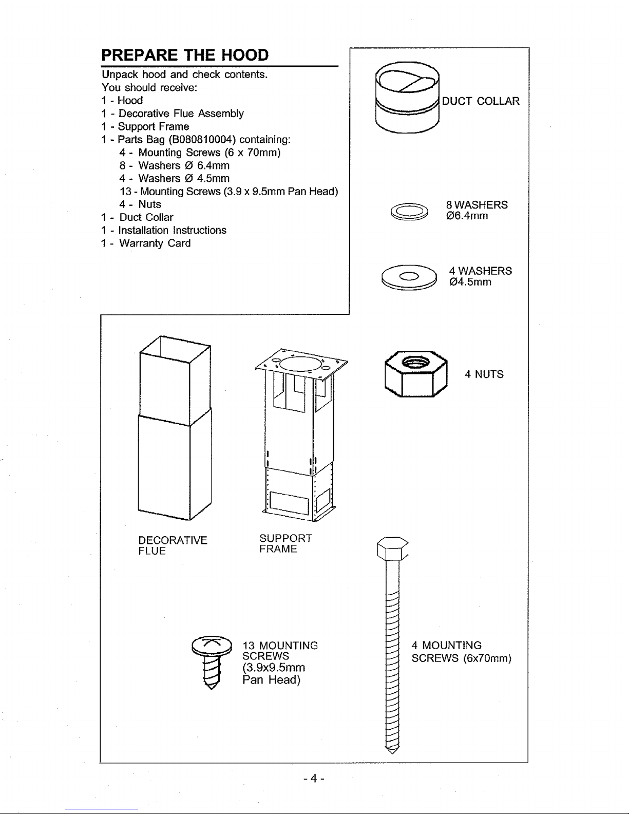
PREPARE THE HOOD
Unpack hood and check contents.
You should receive:
1 - Hood
1 - Decorative Flue Assembly
1 - Support Frame
I - Parts Bag (B080810004) containing:
4- Mounting Screws (6 x 70rnm)
8- Washers O 6.4rnm
4 - Washers O 4.5rnrn
13 - Mounting Screws (3.9 x 9.5mrn Pan Head)
4- Nuts
1 - Duct Collar
1 - Installation Instructions
1 - Warranty Card
DUCT COLLAR
8 WASHERS
_6.4mm
4 WASHERS
O4.5mm
DECORATIVE
FLUE
SUPPORT
FRAME
13 MOUNTING
SCREWS
(3.9x9.5mm
Pan Head)
4 NUTS
>
J
4 MOUNTING
SCREWS (6x70mm)
4
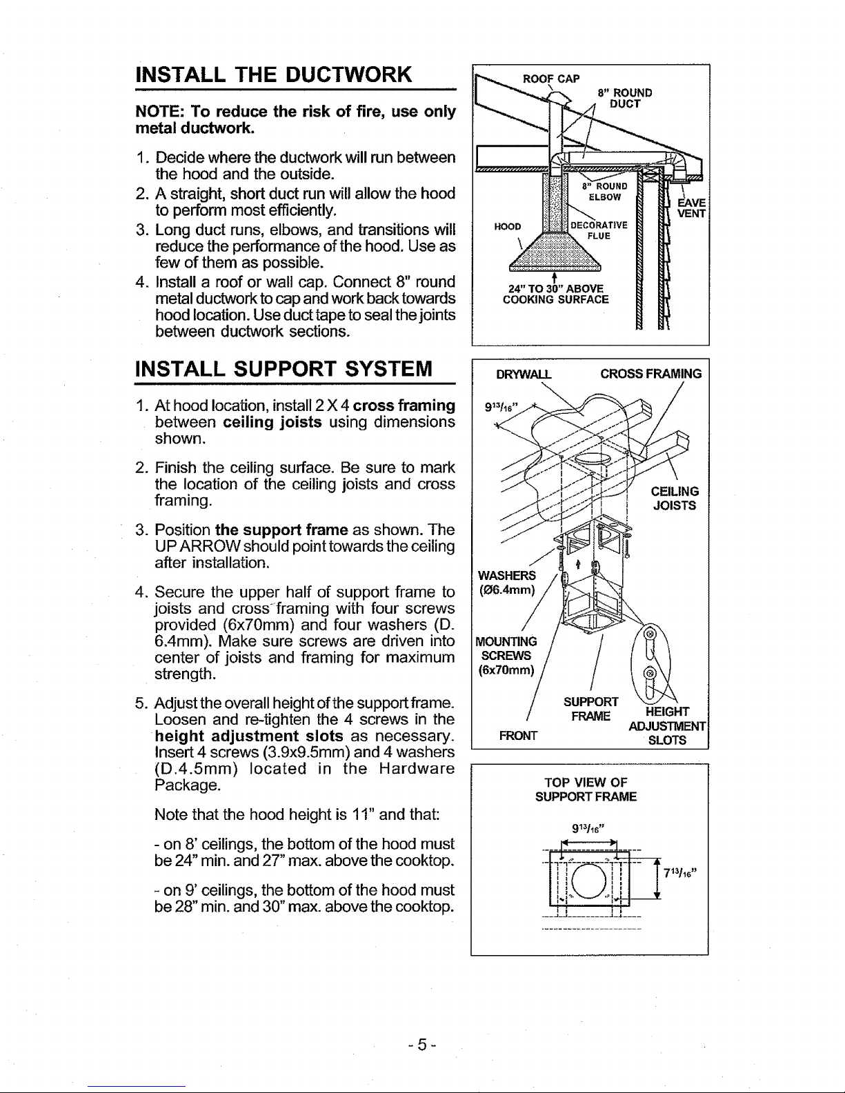
INSTALL THE DUCTWORK
NOTE: To reduce the risk of fire, use only
metal ductwork.
1. Decide where the ductwork will run between
the hood and the outside.
2. A straight, short duct run will allow the hood
to perform most efficiently.
3. Long duct runs, elbows, and transitions will
reduce the performance of the hood. Use as
few of them as possible.
4. Install a roof or wall cap. Connect 8" round
metal ductworktocap and workback towards
hood location. Use duct tape to seal thejoints
between ductwork sections.
INSTALL SUPPORT SYSTEM
1. At hood location, install 2 X 4 cross framing
between ceiling joists using dimensions
shown.
2. Finish the ceiling surface. Be sure to mark
the location of the ceiling joists and cross
framing.
3. Position the support frame as shown. The
UP ARROW should point towards the ceiling
after installation.
4. Secure the upper half of support frame to
joists and crossframing with four screws
provided (6x70mm) and four washers (D.
6.4mm). Make sure screws are driven into
center of joists and framing for maximum
strength.
5. Adjust the overall height of the support frame.
Loosen and re-tighten the 4 screws in the
height adjustment slots as necessary.
Insert 4 screws (3.9x9.5mm) and 4 washers
(D.4.5mm) located in the Hardware
Package.
Note that the hood height is 11" and that:
- on 8' ceilings, the bottom of the hood must
be 24" min. and 27" max. above the cooktop.
- on 9' ceilings, the bottom of the hood must
be 28" min. and 30" max. above the cooktop.
ROOF CAP
\ 8" ROUND
DUCT
f
24" TO 30" ABOVE
COOKING SURFACE
DRYWALL
\
CROSSFRAMING
_
WASHERS
(O6.4mm)
CEILING
1 JOISTS
MOUNTING
SCREWS
(6x70mm)
/
FRONT
SUPPORT
FRAME
HEIGHT
ADJUSTMENT
SLOTS
TOP VIEW OF
SUPPORTFRAME
-5-
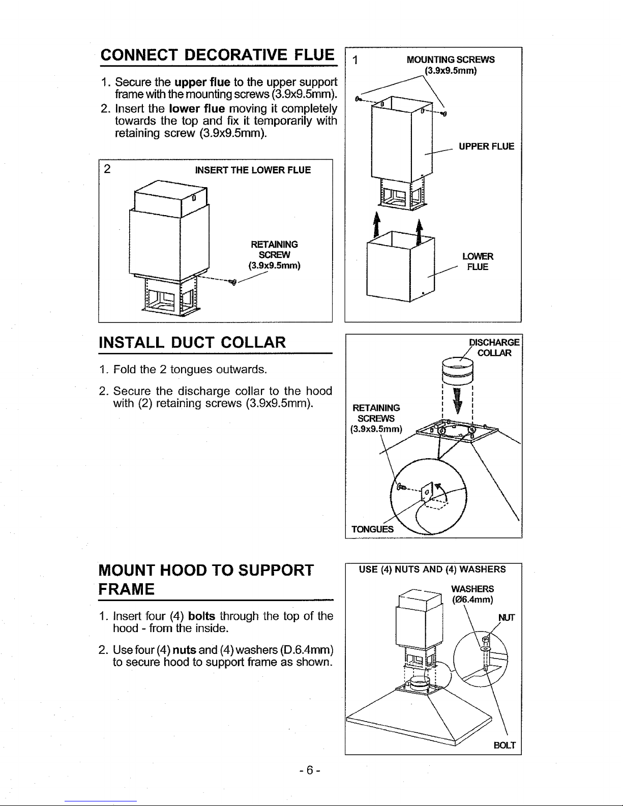
CONNECT DECORATIVE FLUE
1. Secure the upper flue to the upper support
frame with the mounting screws (3.9x9.5mm).
2. Insert the lower flue moving it completely
towards the top and fix it temporarily with
retaining screw (3.9x9.5mm).
INSERT THE LOWER FLUE
RETAINING
SCREW
(3.9x9.Smm)
MOUNTINGSCREWS
UPPER FLUE
LOWER
FLUE
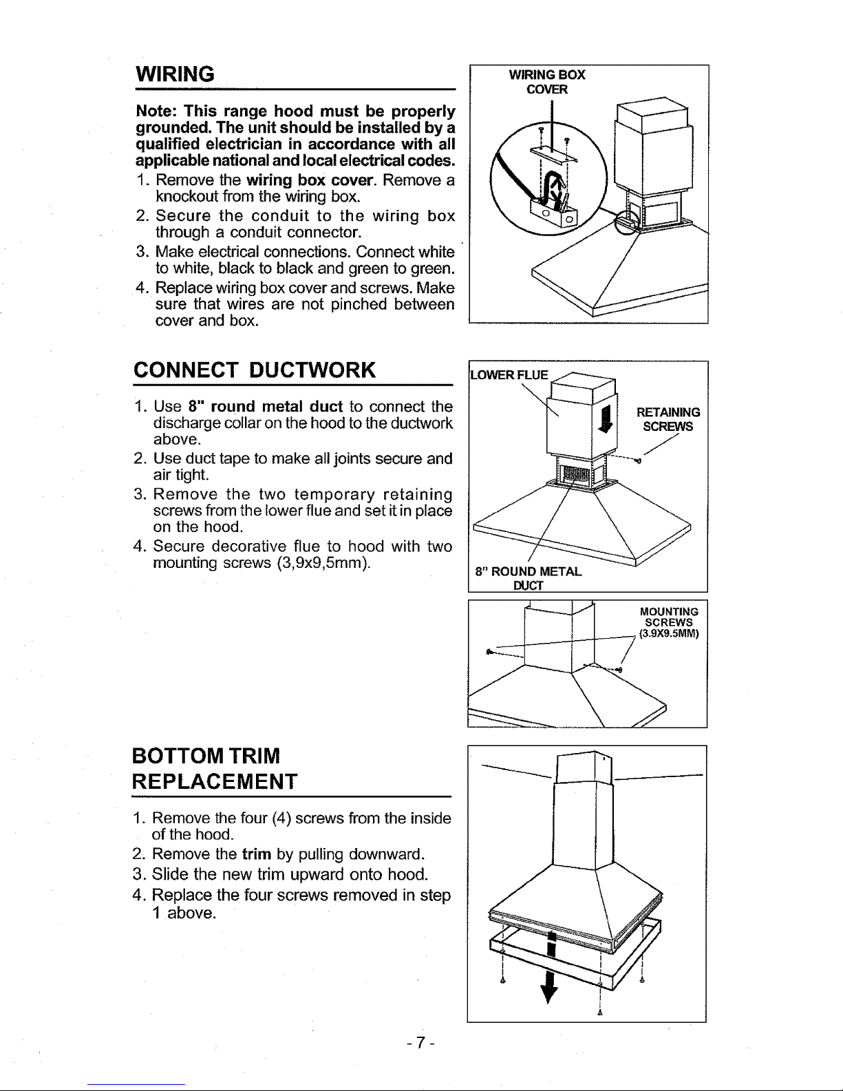
INSTALL DUCT COLLAR
1. Fold the 2 tongues outwards.
2. Secure the discharge collar to the hood
with (2) retaining screws (3.9x9.5mm).
RETAINING
SCREWS
TONGUES
DISCHARGE
!
MOUNT HOOD TO SUPPORT
FRAME
1. Insert four (4) bolts through the top of the
hood - from the inside.
2. Use four (4) nuts and (4) washers (D.6.4mm)
to secure hood to support frame as shown.
USE (4) NUTS AND (4) WASHERS
WASHERS
(06.4mm)
NUT
-6-
BOLT
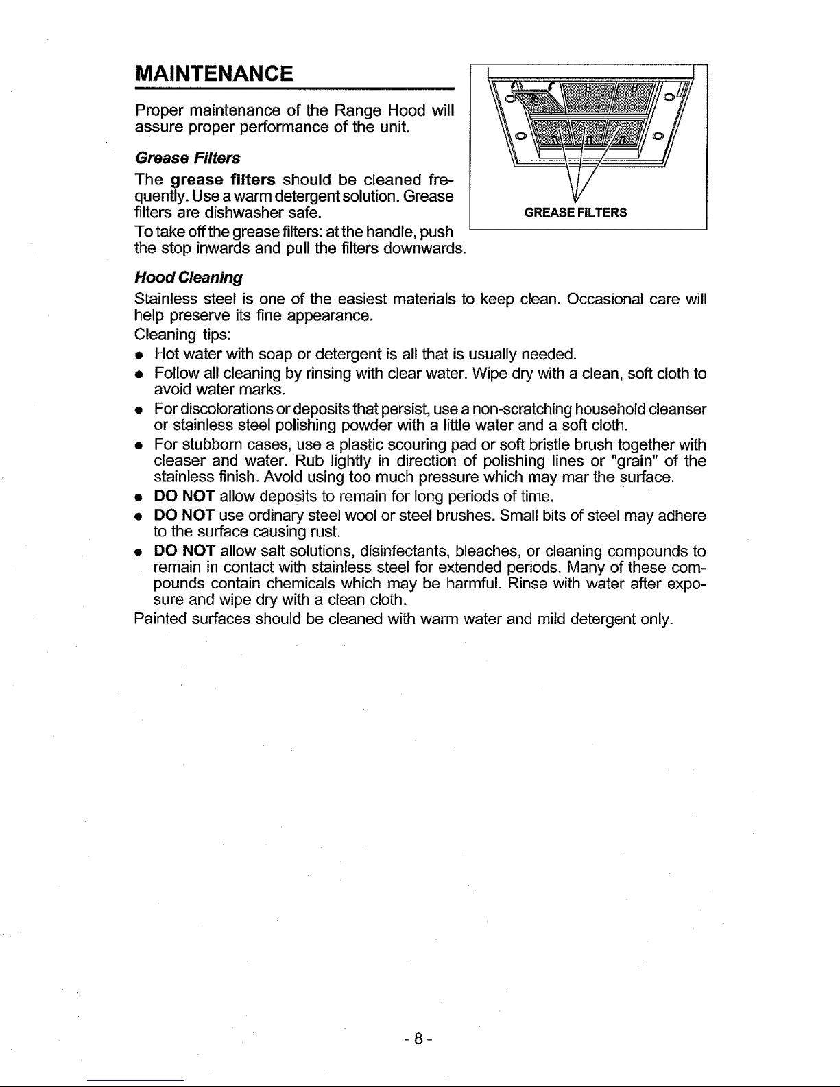
WIRING
Note: This range hood must be properly
grounded. The unit should be installed by a
qualified electrician in accordance with all
applicable national and local electrical codes.
1. Remove the wiring box cover. Remove a
knockout from the wiring box.
2. Secure the conduit to the wiring box
through a conduit connector.
3. Make electrical connections. Connect white
to white, black to black and green to green.
4. Replace wiring box cover and screws. Make
sure that wires are not pinched between
cover and box.
WIRING BOX
COVER
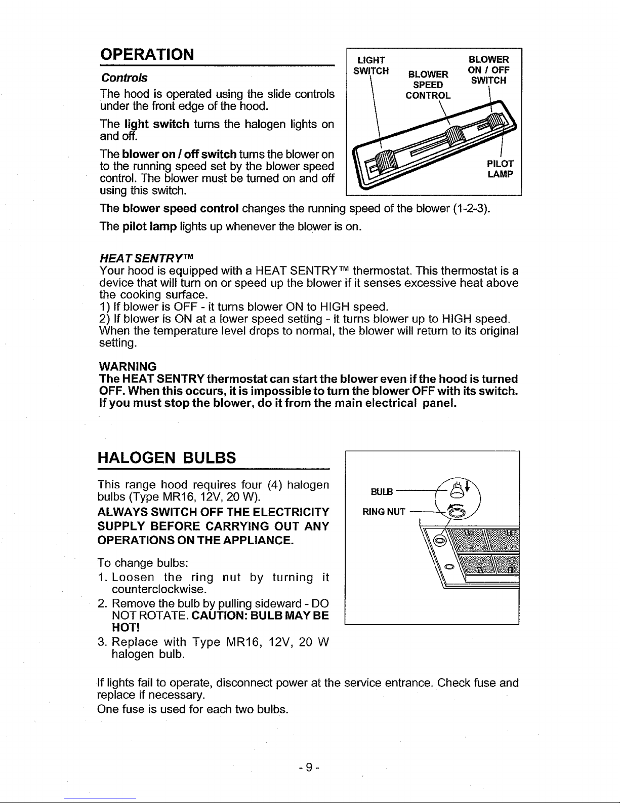
CONNECT DUCTWORK
1. Use 8" round metal duct to connect the
discharge collar on the hood to the ductwork
above.
2. Use duct tape to make all joints secure and
air tight.
3. Remove the two temporary retaining
screws from the lower flue and set it in place
on the hood.
4. Secure decorative flue to hood with two
mounting screws (3,9x9,5mm).
BOTTOM TRIM
REPLACEMENT
1. Remove the four (4) screws from the inside
of the hood.
2. Remove the trim by pulling downward.
3. Slide the new trim upward onto hood.
4. Replace the four screws removed in step
1 above.
LOWER FLUE
RETAINING
SCRLm¢#S
8"ROUND METAL
_ MOUNTING
SCREWS
(3.9xg.5MM)
I
I
I
!
I
7
MAINTENANCE
Proper maintenance of the Range Hood will
assure proper performance of the unit.
Grease Filters
The grease filters should be cleaned fre-
quently. Use a warm detergent solution. Grease
filters are dishwasher safe.
To take off the grease filters: at the handle, push
the stop inwards and pull the filters downwards.
GREASEFILTERS
Hood Cleaning
Stainless steel is one of the easiest materials to keep clean. Occasional care will
help preserve its fine appearance.
Cleaning tips:
• Hot water with soap or detergent is all that is usually needed.
• Follow all cleaning by rinsing with clear water. Wipe dry with a clean, soft cloth to
avoid water marks.
• For discolorations or deposits that persist, use a non-scratching household cleanser
or stainless steel polishing powder with a little water and a soft cloth.
• For stubborn cases, use a plastic scouring pad or soft bristle brush together with
cleaser and water. Rub lightly in direction of polishing lines or "grain" of the
stainless finish. Avoid using too much pressure which may mar the surface.
• DO NOT allow deposits to remain for long periods of time.
• DO NOT use ordinary steel wool or steel brushes. Small bits of steel may adhere
to the surface causing rust.
• DO NOT allow salt solutions, disinfectants, bleaches, or cleaning compounds to
remain in contact with stainless steel for extended periods. Many of these com-
pounds contain chemicals which may be harmful. Rinse with water after expo-
sure and wipe dry with a clean cloth.
Painted surfaces should be cleaned with warm water and mild detergent only.
-8-
OPERATION
Controls
The hood is operated using the slide controls
under the front edge of the hood.
The light switch turns the halogen lights on
and off.
LIGHT BLOWER
SWITCH BLOWER ON / OFF
SPEED SWITCH
CONTROL
The blower on / off switch turns the blower on
to the running speed set by the blower speed
control. The blower must be turned on and off
using this switch.
The blower speed control changes the running speed of the blower (1-2-3).
The pilot lamp lights up whenever the blower is on.
PILOT
LAMP
HEAT SENTRY TM
Your hood is equipped with a HEAT SENTRY TM thermostat. This thermostat is a
device that will turn on or speed up the blower if it senses excessive heat above
the cooking surface.
1) If blower is OFF - it turns blower ON to HIGH speed.
2) If blower is ON at a lower speed setting - it turns blower up to HIGH speed.
When the temperature level drops to normal, the blower will return to its original
setting.
WARNING
The HEAT SENTRY thermostat can start the blower even if the hood is turned
OFF. When this occurs, it is impossible to turn the blower OFF with its switch.
If you must stop the blower, do it from the main electrical panel.
HALOGEN BULBS
This range hood requires four (4) halogen
bulbs (Type MR16, 12V, 20 W).
ALWAYS SWITCH OFF THE ELECTRICITY
SUPPLY BEFORE CARRYING OUT ANY
OPERATIONS ON THE APPLIANCE.
To change bulbs:
1. Loosen the ring nut by turning it
counterclockwise.
2. Remove the bulb by pulling sideward - DO
NOT ROTATE. CAUTION: BULB MAY BE
HOT!
3. Replace with Type MR16, 12V, 20 W
halogen bulb.
BULB
RING NUT
If lights fail to operate, disconnect power at the service entrance. Check fuse and
replace if necessary.
One fuse is used for each two bulbs.
-9-
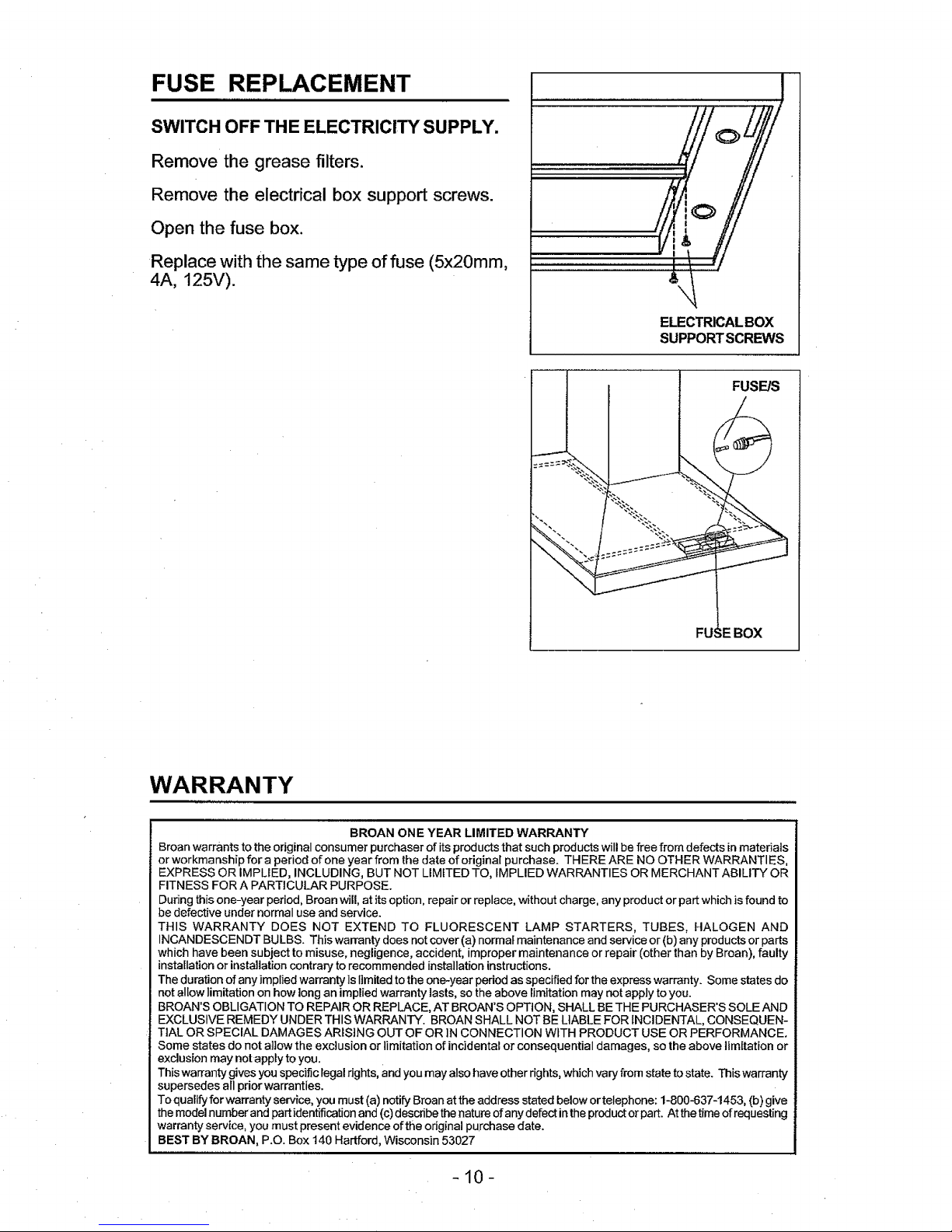
SWITCH OFF THE ELECTRICITY SUPPLY.
Remove the grease filters.
Remove the electrical box support screws.
Open the fuse box.
Replace with the same type offuse (5x20mm,
4A, 125V).
ELECTRICALBOX
SUPPORTSCREWS
FUSE/S
FU )X
WARRANTY
BROAN ONE YEAR LIMITED WARRANTY
Broan warrants to the original consumer purchaser of its products that such products will be free from defects in materials
or workmanship for a period ofone year from the date of original purchase. THERE ARE NO OTHER WARRANTIES,
EXPRESS OR IMPLIED, INCLUDING, BUT NOT LIMITED TO, IMPLIED WARRANTIES OR MERCHANT ABILITY OR
FITNESS FOR A PARTICULAR PURPOSE.
During this one-year period, Broan will, at its option, repair or replace, without charge, any product or part which is found to
be defective under normaluse and service.
THIS WARRANTY DOES NOT EXTEND TO FLUORESCENT LAMP STARTERS, TUBES, HALOGEN AND
INCANDESCENDT BULBS. This warranty does not cover (a) normal maintenance and service or (b) any products or parts
which have been subject to misuse, negligence, accident, improper maintenance or repair (other than by Broan), faulty
installation or installation contrary to recommended installation instructions.
The duration of any implied warranty is limited to the one-year period as specified for the express warranty. Some states do
notallow limitation on how long an implied warranty lasts, so the above limitation may not apply to you.
BROAN'S OBLIGATION TO REPAIR OR REPLACE, AT BROAN'S OPTION, SHALL BE THE PURCHASER'S SOLE AND
EXCLUSIVE REMEDY UNDER THIS WARRANTY. BROAN SHALL NOT BE LIABLE FOR INCIDENTAL, CONSEQUEN-
TIAL OR SPECIAL DAMAGES ARISING OUT OF OR iN CONNECTION WITH PRODUCT USE OR PERFORMANCE.
Some states do not allow the exclusion or limitation of incidental or consequential damages, so theabove limitation or
exclusion may notapply to you.
This warranty gives you specific legalrights, and you may also haveother dghts, which vary from state to state. This warranty
supersedes all prior warranties.
To qualify for warranty service, you must (a) notify Broan at the address stated below or telephone: 1-800-637-1453, (b) give
the model number and part identification and (c) describe thenature ofany defect in the product or part. Atthe time of requesting
warranty service, you must present evidence of the odginal purchase date.
BEST BY BROAN, P.O. Box 140 Hartford, Wisconsin 53027
-10-
 Loading...