

Page 1

Installation &
Owner’s Manual
Guide d'Installation
et d'Utilisation
Manual de Instalación
y del Propietario
Questions? Help is just a moment away!
Preguntas? La ayuda es justa
un momento lejos!
Vous avez des questions? Vous n'avez pas
besoin d'aller loin pour trouver de l'aide!
Call: Transfer Switch Helpline
Llamada: Línea Directa de
Interruptor de Transferencia
Appelez: Ligne Directe de
Commutateur de Transfert
1-800-743-4115 M-F 8-5 CT
Web: www.briggspowerproducts.com
Models 071002 & 071003 Part No. 194942GS Rev.2 (10/27/04)
Page 2

2
Briggs & Stratton Power Products Manual Transfer Switch
Installation and Owner’s Manual
TABLE OF CONTENTS
TABLE OF CONTENTS . . . . . . . . . . . . . . . . . . . . . . . . . . . 2
SAFETY RULES . . . . . . . . . . . . . . . . . . . . . . . . . . . . . . . . . . 3
INTRODUCTION. . . . . . . . . . . . . . . . . . . . . . . . . . . . . . . . 4
For the Home or Business Owner: . . . . . . . . . . . . . . 4
For the Installing Dealer/Contractor: . . . . . . . . . . . . . 4
Owner Orientation . . . . . . . . . . . . . . . . . . . . . . . . . . . 4
Installer Responsibilities . . . . . . . . . . . . . . . . . . . . . . . . 4
Equipment Description. . . . . . . . . . . . . . . . . . . . . . . . . 5
INSTALLATION. . . . . . . . . . . . . . . . . . . . . . . . . . . . . . . . . . 5
Unpacking . . . . . . . . . . . . . . . . . . . . . . . . . . . . . . . . . . . 5
Delivery Inspection . . . . . . . . . . . . . . . . . . . . . . . . 5
Shipment Contents . . . . . . . . . . . . . . . . . . . . . . . . 5
Mounting Dimensions . . . . . . . . . . . . . . . . . . . . . . 5
ESSENTIAL CIRCUIT ISOLATION . . . . . . . . . . . . . . . . . . 6
Mounting Instructions . . . . . . . . . . . . . . . . . . . . . . . . . 7
Power Wiring Interconnections . . . . . . . . . . . . . . . . 7-8
SYSTEM OPERATION. . . . . . . . . . . . . . . . . . . . . . . . . . . . . 9
Specifications. . . . . . . . . . . . . . . . . . . . . . . . . . . . . . . . . 9
Model 071002 . . . . . . . . . . . . . . . . . . . . . . . . . . . . 9
Model 071003 . . . . . . . . . . . . . . . . . . . . . . . . . . . . 9
When Calling The Factory . . . . . . . . . . . . . . . . . . . . . . 9
SERVICE PARTS . . . . . . . . . . . . . . . . . . . . . . . . . . . . . . . . . 10
NOTES . . . . . . . . . . . . . . . . . . . . . . . . . . . . . . . . . . . . 11-12
WARRANTY . . . . . . . . . . . . . . . . . . . . . . . . . . . . . . . . . . . 13
Page 3
3
Briggs & Stratton Power Products Manual Transfer Switch
Installation and Owner’s Manual
SAFETY RULES
This is the safety alert symbol. It is used to
alert you to potential personal injury
hazards. Obey all safety messages that follow
this symbol to avoid possible injury or death.
The safety alert symbol ( ) is used with a signal word
(DANGER, CAUTION,WARNING), a pictorial and/or a
safety message to alert you to hazards. DANGER indicates
a hazard which, if not avoided, will result in death or
serious injury. WARNING indicates a hazard which, if not
avoided, could result in death or serious injury.
CAUTION indicates a hazard which, if not avoided, might
result in minor or moderate injury. CAUTION, when
used without the alert symbol, indicates a situation that
could result in equipment damage. Follow safety messages
to avoid or reduce the risk of injury or death.
The manufacturer cannot possibly anticipate every possible
circumstance that might involve a hazard.The warnings in
this manual, and the tags and decals affixed to the unit are,
therefore, not all-inclusive. If you use a procedure, work
method or operating technique that the manufacturer does
not specifically recommend, you must satisfy yourself that it
is safe for you and others.You must also make sure that the
procedure, work method or operating technique that you
choose does not render the transfer switch unsafe.
• DO NOT touch bare wires or receptacles.
• DO NOT use transfer switch with worn, frayed, bare or
otherwise damaged wiring.
• DO NOT handle electrical cords while standing in water,
while barefoot, or while hands or feet are wet.
• If you must work around a unit while it is operating, stand on
an insulated dry surface to reduce shock hazard.
• DO NOT allow unqualified persons or children to operate or
service transfer switch.
• In case of an accident caused by electrical shock, immediately
shut down the source of electrical power and contact the
local authorities. Avoid direct contact with the victim.
Failure to properly ground transfer switch can
result in electrocution.
WARNING
Only qualified electricians should attempt installation
of this system, which must strictly comply with
applicable codes, standards and regulations.
WARNING
• Use transfer switch only for intended uses.
• If you have questions about intended use, ask dealer or
contact Briggs and Stratton Power Products.
• DO NOT expose transfer switch to excessive moisture, dust,
dirt, or corrosive vapors.
• Despite the safe design of the transfer switch, operating this
equipment imprudently, neglecting its maintenance or being
careless can cause possible injury or death.
• Remain alert at all times while working on this equipment.
NEVER work on the equipment when you are physically or
mentally fatigued.
• If connected devices overheat, turn them off and turn off their
circuit breaker/fuse.
Improper treatment of transfer switch can damage it
and shorten its life.
CAUTION
Page 4

4
Briggs & Stratton Power Products Manual Transfer Switch
Installation and Owner’s Manual
INTRODUCTION
Thank you for your purchase of this Briggs & Stratton
Power Products Manual Transfer Switch.This product is
intended for use with Briggs & Stratton Home Standby
Generator sets ONLY.This is an optional home standby
system which provides an alternate source of electric
power and to serve loads such as heating, refrigeration
systems, and communication systems that, when stopped
during any power outage, could cause discomfort or the
like.This product DOES NOT qualify for emergency
standby as defined by NFPA 70 (NEC).
Briggs and Stratton Power Products (BSPP) has made every
effort to provide for a safe, streamlined and cost-effective
installation. Each installation is unique; it is impossible for
BSPP to know and advise of all conceivable procedures and
methods by which installation might be performed, nor the
potential hazards associated with those methods. For these
reasons,
Only licensed electrical contractors should
install transfer switches. Installations must
strictly comply with all applicable federal,
state and local codes, standards and
regulations.
Your BSPP Transfer Switch is supplied with this combined
“Installation and Owner’s Manual”.This is an important
document and should be retained by the owner after the
installation has been completed.
Every effort has been expended to make sure that the
information in this manual is both accurate and current.
However, the manufacturer reserves the right to change,
alter or otherwise improve the system at any time without
prior notice.
For the Home or Business Owner
To help you make informed choices and communicate
effectively with your installation contractor(s),
Read and understand the
Owner Orientation Section of this manual
BEFORE
contracting or starting
your transfer switch installation.
To arrange for proper installation, contact the store at
which you purchased your BSPP Transfer Switch, your
dealer, or your utility power provider.
The Transfer Switch Warranty is VOID
unless the system is installed by a
licensed electrical professional.
For the Installing Dealer/Contractor
Check federal, state and local codes for questions on
installation.
If you need more information about the transfer switch,
call 1-800-743-4115, between 8:00 AM and 5:00 PM CT.
Owner Orientation
The illustrations are for typical circumstances and are
meant to familiarize you with the installation options
available with your transfer switch.
Local codes, appearance, and distances are the factors that
must be considered when negotiating with an installation
professional.As the distance from the existing electrical
service increases, compensation in wiring materials must be
allowed for.This is necessary to comply with local codes
and overcome electrical voltage drops.
The factors mentioned above will have a direct effect
on the overall price of your transfer switch installation.
NOTE:Your installer must check local codes AND obtain
permits before installing the system.
• Read and follow the instructions given in this manual.
• Follow a regular schedule in caring for and using your
transfer switch, as specified in the manual.
Installer Responsibilities
• Read and observe the safety rules.
• Read and follow the instructions given in this manual.
• Check federal, state and local codes.
Page 5
5
Briggs & Stratton Power Products Manual Transfer Switch
Installation and Owner’s Manual
Equipment Description
These transfer switches are intended to operate
compatible electrical loads of normal residential
installations.The load is connected either to utility power
(normal) or home standby power (emergency).
These manual transfer switches are equipped with two
circuit breakers (“GENERATOR SUPPLY” and “UTILITY
SUPPLY”) and a mechanical interlock.The “GENERATOR
SUPPLY” circuit breaker provides power from the
generator to the load devices wired to the manual transfer
switch.The “UTILITY SUPPLY” circuit breaker provides
utility power from the distribution panel to the load
devices wired to the manual transfer switch.
The mechanical interlock allows the circuit breakers for
either the generator power “GENERATOR SUPPLY” or the
utility power “UTILITY SUPPLY” to be turned on to
provide power to the selected house loads.These manual
transfer switches will not allow utility line power and
generator power to be connected to a load device at the
same time.
If utility line power is restored while generator power is
being used, there will be no affect on the generator or
transfer switch components.When utility power is
restored, follow the instructions in the section “System
Operation”.
INSTALLATION
Unpacking
Delivery Inspection
After removing the carton, carefully inspect the transfer
switch components for any damage that may have occurred
during shipment.
IMPORTANT: If loss or damage is noted at time of
delivery, have the person(s) making delivery note all damage
on the freight bill and affix his signature under the
consignor's memo of loss or damage. If loss or damage is
noted after delivery, contact the carrier for claim
procedures. Freight damaged parts are not warranted.
Shipment Contents
• Manual Power Transfer Switch
• Installation and Owner’s Manual
Mounting Dimensions
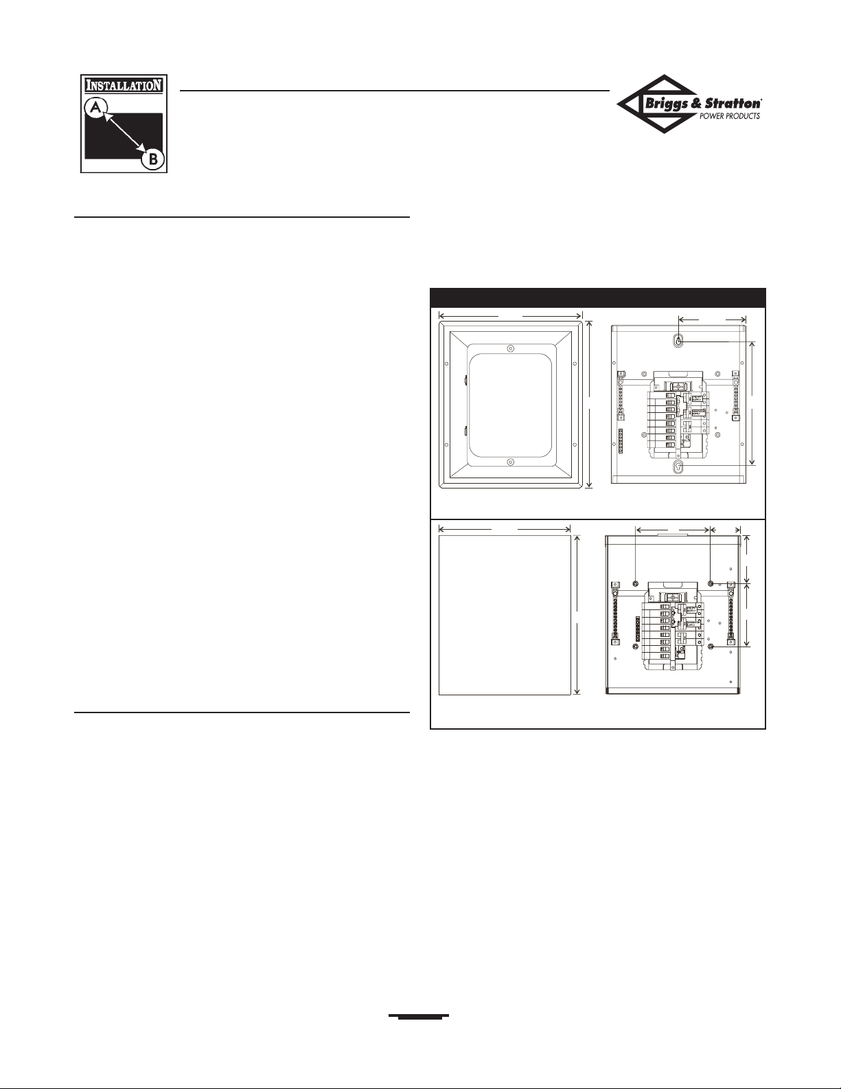
Figure 1 depicts the physical size and mounting hole
locations of the manual transfer switch enclosure.The
transfer switch enclosure is commonly secured through the
predrilled holes, as shown.
Figure 1 — Manual Power Transfer Switch Dimensions
Model 071002
Model 071003
Enclosure Dimensions
Mounting Dimensions
Enclosure Dimensions
Mounting Dimensions
14.25”
16.875”
7.125”
13”
16.75”
14.25”
5”
6.625”
3.125”
8”
Page 6

6
Briggs & Stratton Power Products Manual Transfer Switch
Installation and Owner’s Manual
ESSENTIAL CIRCUIT
ISOLATION
Essential electrical loads are loads that will be powered by
the Standby Generator System. Essential loads are grouped
together and wired into the transfer switch.
TO THE INSTALLER: Consult with Standby
Generator System owner(s) to discuss their
“Selection of Essential Circuits”, described in
owner’s manual.
Ensure that the total of the selected load circuits fed by this
transfer switch are within the generator's rated capacity.
The following requirements apply to this type of isolation
system:
• The Manual Transfer Switch is installed after the main
distribution panel.
• The Manual Transfer Switch has a load rating of 60 Amps.
This is the maximum load rating of the essential loads.
All wiring must conform to national, state and local codes.
The illustration in Figure 2 depicts the Standby Generator
System and assumes the utility is supplying 120/240 Volt,
single-phase electrical service.
Figure 2 — Typical System Diagram with Essential Circuits
To Utility Power
Watt Meter
Main Distribution Panel
To Air Conditioner (240V)
To Other Circuits (120V)
To Range
To Water Heater
240V
To Briggs & Stratton
Standby Generator
120V To Microwave
120 V To Bathroom
240V To Well Pump
120V To Sump Pump
120V
To Furnace Blower
To Lights
To Refrigerator
120V To Freezer
Manual Transfer Switch
(in utility position)
Neutral
Utility Supply
Generator Supply
Page 7
7
Briggs & Stratton Power Products Manual Transfer Switch
Installation and Owner’s Manual
Mounting Guidelines
The Model 071002 Manual Transfer Switch is enclosed in a
NEMA Type 1 enclosure suitable for indoor use only.
The Model 071003 Manual Transfer Switch is enclosed in a
NEMA Type 3R enclosure suitable for indoor/outdoor use.
Guidelines for mounting the Manual Transfer Switch
include:
• Model 071003 Manual Transfer Switch must be installed
with minimum NEMA 3R hardware for conduit
connections.
• Install the switch on a firm, sturdy supporting structure.
• To assure easy insertion or removal of circuit breakers,
level and plumb the enclosure.This can be done by
placing washers between the switch enclosure and the
mounting surface.
• NEVER install the switch where any corrosive substance
might drip onto the enclosure.
• Protect the switch at all times against excessive moisture,
dust, dirt, lint, construction grit and corrosive vapors.
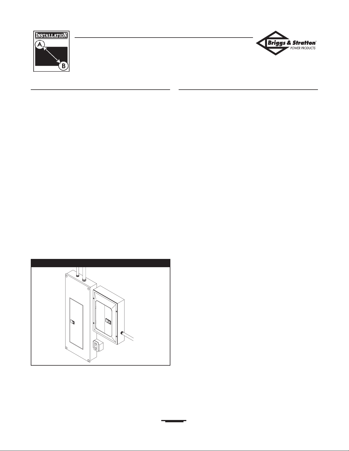
The typical installation of the Manual Power Transfer Switch
is depicted in Figure 3. Discuss layout suggestions/changes
with the owner before beginning the system installation
process.
Power Wiring Interconnections
All wiring must be the proper size, properly supported, of
approved insulation qualities,and protected by NEC
approved conduit.
Complete the following connections between the
generator, transfer switch and main distribution panel
(Figure 4, on next page).
1. Connect utility power supply leads from two pole
breaker installed in main distribution panel to transfer
switch two pole breaker marked “UTILITY SUPPLY”. A
60 Amp circuit breaker is provided. Ensure breaker is
turned OFF.
2. Connect main distribution panel ground to transfer
switch “GND” bus.
3. Connect main distribution panel neutral lead to
transfer switch “NEUTRAL” terminal.
4. Connect generator power supply leads from
generator’s control panel to transfer switch two pole
breaker marked “GENERATOR SUPPLY”.
5. Connect generator Neutral from control panel to
transfer switch “NEUTRAL” terminal.
6. Connect generator “GND” from control panel to
transfer switch “GND” terminal.
7. Tighten all wire connections/fasteners to proper
torque.
Manual
Transfer Switch
Main
Distribution
Panel
Figure 3 — Typical Switch Mounting
Model 071002 shown
Page 8

8
Briggs & Stratton Power Products Manual Transfer Switch
Installation and Owner’s Manual
Figure 4 — A Typical Installation Diagram for Transfer Switch
MODEL 071003
MODEL 071002
Main Distribution Panel
Ground Bus
Neutral
Bus
To Generator
Generator
Connection
Utility
Connection
Main Distribution Panel
Ground Bus
Neutral
Bus
To Generator
Generator
Connection
Neutral
Bus
Neutral
Bus
Utility
Connection
Page 9

9
Briggs & Stratton Power Products Manual Transfer Switch
Installation and Owner’s Manual
SYSTEM OPERATION
To transfer from utility power to generator power:
1. Turn OFF main breaker labeled “UTILITY SUPPLY”.
2. Turn OFF all branch circuit breakers in transfer switch.
3. Slide mechanical interlock and turn “GENERATOR
SUPPLY” breaker to ON position.
4. Turn ON branch circuit breakers one at a time.
To transfer from generator power back to utility
power:
1. Turn OFF main breaker labeled “GENERATOR
SUPPLY”.
2. Turn OFF all branch circuit breakers in transfer switch.
3. Slide mechanical interlock and turn “UTILITY SUPPLY”
breaker to ON position.
4. Turn ON branch circuit breakers one at a time.
Specifications
UL® 1008 Listed Transfer Switch
Model 071002
Enclosure. . . . . . . . . . . . . . . . . . . NEMA 1
Maximum Load/Circuit:
from Load Center . . . . . . . . . . 60 Amps
Rated AC Voltage. . . . . . . . . . . . . 250 Volts
Poles . . . . . . . . . . . . . . . . . . . . . . 2
Fault Current Rating . . . . . . . . . . 10,000 RMS Symmetrical
Amperes
Weight . . . . . . . . . . . . . . . . . . . . . 27 lbs.
Model 071003
Enclosure. . . . . . . . . . . . . . . . . . . NEMA 3R
Maximum Load/Circuit:
from Load Center . . . . . . . . . . 60 Amps
Rated AC Voltage. . . . . . . . . . . . . 250 Volts
Poles . . . . . . . . . . . . . . . . . . . . . . 2
Fault Current Rating . . . . . . . . . . 10,000 RMS Symmetrical
Amperes
Weight . . . . . . . . . . . . . . . . . . . . . 34 lbs.
When Calling the Factory
Before contacting Briggs and Stratton Power Products
regarding service or repair of this transfer switch, obtain
the Model Number from the unit data decal located on or
inside the case.
To contact Briggs and Stratton Power Products call
1-800-743-4115, between 8:00 AM and 5:00 PM CT.
Page 10

10
Briggs & Stratton Power Products Manual Transfer Switch
Installation and Owner’s Manual
TRANSFER SWITCH SERVICE PARTS
MODEL 071002 (NEMA 1)
Part # Description
195566GS KIT, HRDWR, NEMA1, SRV
195568GS KIT, DOOR, NEMA1, SRV
194942GS MANUAL, Owner’s
MODEL 071003 (NEMA 3R)
Part # Description
195567GS KIT, HRDWR, NEMA3R, SRV
195569GS DEADFRONT, NEMA3R, SRV
195570GS DOOR, NEMA3R, SRV
194942GS MANUAL, Owner’s
Page 11

11
Briggs & Stratton Power Products Manual Transfer Switch
Installation and Owner’s Manual
NOTES
Page 12

12
Briggs & Stratton Power Products Manual Transfer Switch
Installation and Owner’s Manual
NOTES
Page 13

BRIGGS & STRATTON POWER PRODUCTS GROUP, LLC EQUIPMENT OWNER WARRANTY POLICY
LIMITED WARRANTY
Briggs & Stratton Power Products Group, LLC will repair or replace, free of charge, any part(s) of the equipment that is defective in material
or workmanship or both. Transportation charges on parts submitted for repair or replacement under this warranty must be borne by
purchaser. This warranty is effective for the time periods and subject to the conditions stated below. For warranty service, find the nearest
Authorized Service Dealer in our dealer locator map at www.briggspowerproducts.com.
THERE IS NO OTHER EXPRESS WARRANTY. IMPLIED WARRANTIES, INCLUDING THOSE OF MERCHANTABILITY AND FITNESS
FOR A PARTICULAR PURPOSE, ARE LIMITED TO ONE YEAR FROM PURCHASE, OR TO THE EXTENT PERMITTED BY LAW ANY
AND ALL IMPLIED WARRANTIES ARE EXCLUDED. LIABILITY FOR INCIDENTAL OR CONSEQUENTIAL DAMAGES ARE EXCLUDED
TO THE EXTENT EXCLUSION IS PERMITTED BY LAW. Some states or countries do not allow limitations on how long an implied warranty
lasts, and some states or countries do not allow the exclusion or limitation of incidental or consequential damages, so the above limitation
and exclusion may not apply to you. This warranty gives you specific legal rights and you may also have other rights which vary from state
to state or country to country.
OUR EQUIPMENT*
OUTBOARD
MOTOR
PRESSURE
WASHER
WATER PUMP
(Not available in the
USA)
PORTABLE
GENERATOR
WELDER
Less tthan 110 KKW 10 KKW oor ggreater
Transfer sswitch
2 years
none
1 year
90 days
1 year
90 days
2 years
1 year
2 years
none
3 years or
1500 hours
none
3 years
none
WARRANTY PERIOD**
HOME STANDBY GENERATOR SYSTEM
Consumer Use
Commercial Use
* The engine and starting batteries are warranted solely by the manufacturers of those products.
** 2 years for all consumer products in the European Union. Parts only on 2nd year for consumer use of Portable Generator and
Home Standby Generator System - Less than 10 KW, outside of European Union.
The warranty period begins on the date of purchase by the first retail consumer or commercial end user, and continues for the period of time
stated in the table above. “Consumer use" means personal residential household use by a retail consumer. “Commercial use" means all other
uses, including use for commercial, income producing or rental purposes. Once equipment has experienced commercial use, it shall thereafter
be considered as commercial use for purposes of this warranty. Equipment used for prime power in place of utility are not applicable to
this warranty. Electric powered pressure washers used for commercial purposes are not warranted.
NO WARRANTY REGISTRATION IS NECESSARY TO OBTAIN WARRANTY ON BRIGGS & STRATTON PRODUCTS. SAVE YOUR
PROOF OF PURCHASE RECEIPT. IF YOU DO NOT PROVIDE PROOF OF THE INITIAL PURCHASE DATE AT THE TIME WARRANTY
SERVICE IS REQUESTED, THE MANUFACTURING DATE OF THE PRODUCT WILL BE USED TO DETERMINE THE WARRANTY
PERIOD.
ABOUT YOUR WARRANTY
We welcome warranty repair and apologize to you for being inconvenienced. Any Authorized Service Dealer may perform warranty repairs. Most
warranty repairs are handled routinely, but sometimes requests for warranty service may not be appropriate. For example, warranty service would not
apply if equipment damage occurred because of misuse, lack of routine maintenance, shipping, handling, warehousing or improper installation.
Similarly, the warranty is void if the manufacturing date or the serial number on the equipment has been removed or the equipment has been altered
or modified. During the warranty period, the Authorized Service Dealer, at its option, will repair or replace any part that, upon examination, is found to
be defective under normal use and service. This warranty will not cover the following repairs and equipment:
• Normal Wear: Outdoor Power Equipment, like all mechanical devices, needs periodic parts and service to perform well. This warranty does not
cover repair when normal use has exhausted the life of a part or the equipment.
• Installation and Maintenance: This warranty does not apply to equipment or parts that have been subjected to improper or unauthorized
installation or alteration and modification, misuse, negligence, accident, overloading, overspeeding, improper maintenance, repair or storage so as,
in our judgment, to adversely affect its performance and reliability. This warranty also does not cover normal maintenance such as adjustments,
fuel system cleaning and obstruction (due to chemical, dirt, carbon, lime, etc.).
• Other Exclusions: This warranty excludes wear items such as quick couplers, oil gauges, belts, o-rings, filters, pump packing, etc., pumps that
have been run without water supplied or damage or malfunctions resulting from accidents, abuse, modifications, alterations, or improper servicing
or freezing or chemical deterioration. Accessory parts such as guns, hoses, wands and nozzles are excluded from the product warranty. This
warranty excludes failures due to acts of God and other force majeure events beyond the manufacturers control. Also excluded is used,
reconditioned, and demonstration equipment; equipment used for prime power in place of utility power and equipment used in life support
applications.
BRIGGS & STRATTON POWER PRODUCTS GROUP, LLC
JEFFERSON, WI, USA
Effective September 1, 2004 replaces all undated Warranties and all Warranties dated before September 1, 2004
Page 14

14
Commutateur de transfert manuel Briggs & Stratton Power Products
Guide d'installation et d'utilisation
TABLE DES MATIÈRES. . . . . . . . . . . . . . . . . . . . . . . . . . . . . . . . . 14
RÈGLES DE SÉCURITÉ . . . . . . . . . . . . . . . . . . . . . . . . . . . . . . . . 15
INTRODUCTION . . . . . . . . . . . . . . . . . . . . . . . . . . . . . . . . . . . . 16
Au Propriétaire Résidentiel ou Commercial . . . . . . . . . . . . 16
Au Détaillant/à l'Entrepreneur Procédant à
l'Installation. . . . . . . . . . . . . . . . . . . . . . . . . . . . . . 16
Conseils au Propriétaire. . . . . . . . . . . . . . . . . . . . . . . . . . . . 16
Responsabilités de l'Installateur . . . . . . . . . . . . . . . . . . . . . . 16
Description de l'Équipement . . . . . . . . . . . . . . . . . . . . . . . . 17
INSTALLATION . . . . . . . . . . . . . . . . . . . . . . . . . . . . . . . . . . . . . . 17
Déballage . . . . . . . . . . . . . . . . . . . . . . . . . . . . . . . . . . . . . . . 17
Vérification de la Livraison. . . . . . . . . . . . . . . . . . . . . . 17
Contenu de la Boîte . . . . . . . . . . . . . . . . . . . . . . . . . . . 17
Dimensions d'Installation . . . . . . . . . . . . . . . . . . . . . . . 17
ISOLATION DES CIRCUITS ESSENTIELS . . . . . . . . . . . . . . . . . 18
Instructions d'Installation . . . . . . . . . . . . . . . . . . . . . . . . . . . 19
Interconnexions du Câblage d'Alimentation . . . . . . . . . 19-20
FONCTIONNEMENT DU SYSTÈME
. . . . . . . . . . . . . . . . . . . 21
Caractéristiques . . . . . . . . . . . . . . . . . . . . . . . . . . . . . . . . . . 21
Modèle 071002. . . . . . . . . . . . . . . . . . . . . . . . . . . . . . . 21
Modèle 071003. . . . . . . . . . . . . . . . . . . . . . . . . . . . . . . 21
Si vous Devez Communiquer avec l'Usine . . . . . . . . . . . . . 21
REMARQUES . . . . . . . . . . . . . . . . . . . . . . . . . . . . . . . . . . . . . . . . 22
LISTES DES PIÈCES . . . . . . . . . . . . . . . . . . . . . . . . . . . . . . . . . . . 10
GARANTIE. . . . . . . . . . . . . . . . . . . . . . . . . . . . . . . . . . . . . . . . . . 23
TABLE DES MATIÈRES
Page 15

15
Commutateur de transfert manuel Briggs & Stratton Power Products
Guide d'installation et d'utilisation
RÈGLES DE SÉCURITÉ
Ceci est la sûreté le symbole vif. Il est utilisé pour
vous alerter aux dangers de blessure personnels
potentiels. Obéir tous messages de sûreté qui suivent
ce symbole éviter la blessure ou la mort possibles.
Le symbole indiquant un message de sécurité est accompagné d'un
mot indicateur (DANGER,ATTENTION,AVERTISSEMENT), d'un
message illustré et/ou d'un message de sécurité visant à vous
avertir des dangers.DANGER indique un danger qui, s'il n'est pas
évité, provoquera des blessures graves, voire fatales.
AVERTISSEMENT indique un danger qui,s'il n'est pas évité, peut
provoquer des blessures graves, voire fatales. ATTENTION
indique un danger qui, s'il n'est pas évité, peut provoquer des
blessures mineures ou légères.Le mot ATTENTION, lorsqu'il est
utilisé sans le symbole d'alerte, indique une situation pouvant
endommager l'équipement. Suivez les messages de sécurité pour
éviter ou réduire les risques de blessures ou de mort.
Le fabriquant ne peut anticiper toutes les circonstances
potentielles pouvant comporter un danger. Par conséquent, les
avertissements contenus dans le présent manuel, ainsi que les
plaques et les décalques apposés sur l'unité n'englobent pas toutes
les possibilités. Si vous utilisez une procédure, une méthode de
travail ou une technique d'opération non spécifiquement
recommandée par le fabricant, vous devez vous assurer qu'elle ne
compromet pas votre sécurité ni celle des autres.Vous devez
également vous assurer que la procédure, la méthode de travail
ou la technique d'opération que vous choisissez ne rende pas la
commutateur de transfert dangereuse.
Seuls les électriciens qualifiés peuvent procéder à l'installation
de ce système, laquelle doit se conformer strictement aux
codes, aux normes et aux réglementations applicables.
AVERTISSEMENT
• NE touchez PAS les fils dénudés ou les boîtiers.
• N'utilisez PAS le commutateur de transfert avec des cordons
électriques usés, effilochés ou dénudés, ou abîmés de quelque sorte
que ce soit.
• NE manipulez PAS les cordons d'alimentation lorsque vous êtes
debout dans l'eau, pieds nus ou avec les mains ou les pieds humides.
• Si vous devez travaillez autour d'une unité alors qu'elle est en marche,
placez-vous sur une surface sèche isolée afin de réduire les risques de
choc électrique.
• NE laissez PAS des personnes non qualifiées ou des enfants se servir
ou réparer le commutateur de transfert.
• En cas d'accident causé par un choc électrique, procédez
immédiatement à la mise hors tension de l'alimentation électrique et
contacter des autorités locales. Évitez tout contact direct avec la
victime.
Ne pas relier le commutateur de transfert à la terre
risque de provoquer des électrocutions.
AVERTISSEMENT
• Ne vous servez du commutateur de transfert que pour les utilisations
prévues.
• Si vous avez des questions concernant les utilisations prévues,
demandez à votre distributeur ou contactez Briggs and Stratton
Power Products.
• N'exposez PAS le commutateur de transfert à une humidité excessive,
à de la poussière, à de la saleté ou à des vapeurs corrosives.
• En dépit de la conception sécuritaire du commutateur de transfert, le
fait d'opérer l'équipement de façon imprudente, de ne pas l'entretenir
ou d'être négligent peut causer des blessures et la mort.
• Demeurez alerte en tout temps lorsque vous travaillez sur cet
équipement. NE travaillez JAMAIS sur l'équipement si vous êtes fatigué
physiquement ou mentalement.
• Si les appareils branchés surchauffent, éteignez-les et mettez leur
disjoncteur ou fusible hors tension.
Un traitement inapproprié du commutateur de transfert
risque de l'endommager et de raccourcir sa durée d'utilisation.
ATTENTION
Page 16

16
Commutateur de transfert manuel Briggs & Stratton Power Products
Guide d'installation et d'utilisation
INTRODUCTION
Nous vous remercions d'avoir acheté ce commutateur de
transfert manuel de Briggs & Stratton Power Products (BSPP). Ce
commutateur de transfert convient UNIQUEMENT aux
génératrices de secours résidentielles Briggs & Stratton. Ce
produit est conçu pour être utilisé comme groupe électrogène
optionnel fournissant une source d'électricité alternative et pour
desservir des charges comme le chauffage, les systèmes de
réfrigération et les systèmes de communication qui, lorsqu'ils sont
arrêtés durant une panne d'électricité, peuvent causer des
inconforts ou autre. Ce produit ne se qualifie pas comme groupe
électrogène d'urgence tel que défini par la NFPA 70 (NEC).
La société Briggs & Stratton Power Products (BSPP) a tout fait
pour fournir un commutateur de transfert dont l'installation soit
sécuritaire, facile et économique. Comme chaque installation est
unique, il est impossible de connaître et de recommander une
marche à suivre présentant toutes les méthodes et consignes
d'installation possibles. Briggs et Stratton ignore également les
dangers et/ou les résultats potentiels de chaque méthode ou
procédure. C'est pourquoi,
Seuls des entrepreneurs en électricité qualifiés devraient
procéder à l'installation des commutateur de transfert.
Toute installation doit être conforme à tous codes de
sécurité applicables, ainsi qu'aux normes et à la
réglementation de l'industrie.
Votre commutateur de transfert BSPP est livré avec le présent
"Guide d'installation et d'utilisation". Ce guide est un document
important; conservez-le après avoir complété l'installation.
Tout a été fait pour s'assurer que les renseignements contenus
dans le présent guide soient exacts et à jour.Toutefois, le
fabriquant se réserve le droit de changer, de modifier ou encore
d'améliorer le système en tout temps, et ce, sans préavis.
Au Propriétaire Résidentiel ou
Commercial
Afin de vous aider à faire des choix avisés et à communiquer
efficacement avec l'entrepreneur qui procédera à l'installation,
Veuillez lire avec soin la section Conseils au propriétaire
dans le présent guide avant de contracter un
entrepreneur ou de commencer l'installation de votre
commutateur de transfert.
Pour assurer une installation adéquate, veuillez contacter le
magasin qui vous a vendu votre commutateur de transfert Briggs
& Stratton Power Products, votre détaillant ou votre fournisseur
de services d'électricité.
Si l'installation du commutateur de transfert n'est pas
effectuée par des professionnels certifiés en
électricité, la garantie sera ANNULÉE
.
Au Détaillant ou à l'Entrepreneur
Procédant à l'Installation
Le présent guide contient tous les renseignements nécessaires
à l'installation adéquate du commutateur de transfert pour la
plupart des usages.
Si vous avez besoin de renseignements supplémentaires,
veuillez appeler au (800) 743-4115 de 8 h à 17 h HNC.
Conseils au Propriétaire
Les illustrations se rapportent à des cas typiques et ont pour but
de vous familiariser avec les différentes options d'installation de
votre commutateur de transfert dont vous disposez.
Au moment de négocier avec un installateur professionnel, il
faudra tenir compte des facteurs suivants : les codes de sécurité
locaux, l'apparence, le niveaux de bruits, et les distances.
Souvenez-vous que plus grandes sont les distances entre le groupe
électrogène et le service électrique existant ainsi que
l'alimentation, plus il faudra faire des compensations dans les
matériaux et le câblage. Ces modifications sont nécessaires pour
vous conformer aux codes de sécurité locaux et pour surmonter
les chutes de tension.
Les facteurs mentionnés ci-dessus auront une incidence
directe sur le prix total de l'installation de votre
commutateur de transfert.
REMARQUE: Votre installateur est tenu de vérifier les codes
locaux ET d'obtenir les permis requis avant de procéder à
l'installation du système.
• Vous devez lire et suivre les instructions indiquées dans le
manuel.
• Établissez un programme d'entretien, de soins et d'utilisation
régulier de votre commutateur de transfert, tel qu'indiqué
dans le manuel.
Responsabilités de l'Installateur
• Vous devez lire et respecter les règles de sécurité décrites
dans le manuel.
• Vous devez lire et suivre les instructions indiquées dans le
présent le manuel.
• Vérifiez tous les codes fédéraux, provinciaux et locaux.
Page 17

17
Commutateur de transfert manuel Briggs & Stratton Power Products
Guide d'installation et d'utilisation
Description de l'Équipement
Ces commutateurs de transfert ont été conçus pour des charges
électriques compatibles d'équipements résidentiels courants. La
charge est branchée soit à l'alimentation de service (normal), soit
à la génératrice de secours résidentielle (urgence).
Ces commutateurs de transfert manuels sont équipés de deux
disjoncteurs ("GENERATOR SUPPLY" [alimentation de la
génératrice] et "UTILITY SUPPLY" [alimentation de service]) ainsi
que d'un contacteur d'interdiction mécanique. Le disjoncteur
"GENERATOR SUPPLY" fournit l'alimentation de la génératrice
aux appareils de charge reliés au commutateur de transfert
manuel. Le disjoncteur "UTILITY SUPPLY" fournit l'alimentation de
service du panneau de distribution aux appareils de charge reliés
au commutateur de transfert manuel.
Le contacteur d'interdiction mécanique permet au disjoncteur soit
de l'alimentation de la génératrice, "GENERATOR SUPPLY", soit
de l'alimentation de service, "UTILITY SUPPLY", d'alimenter les
charges résidentielles sélectionnées. Ces commutateurs de
transfert manuels ne permettent pas à l'alimentation de service et
à l'alimentation de la génératrice d'être simultanément branchés à
un appareil de la charge.
Le rétablissement de l'alimentation de service alors que
l'alimentation de la génératrice est utilisée n'aura aucune incidence
sur la génératrice. Lorsque l'alimentation de service est rétablie,
suivez les instruction de la section "Fonctionnement du système".
INSTALLATION
Déballage
Vérification de la Livraison
Après avoir enlevé le carton, examinez avec soin les éléments du
commutateur de transfert manuel pour tout dommage subi
durant l'expédition.
IMPORTANT: Au moment de la livraison, si vous remarquez des
dommages ou des pièces manquantes, demandez au livreur de
noter tous les dommages sur la facture de fret et d'apposer sa
signature dans l'espace réservé à cet effet.Après la livraison, si
vous remarquez des pièces manquantes ou des dommages,mettez
les pièces endommagées de côté et communiquez avec le
transporteur pour connaître les procédures de réclamation. Les
pièces manquantes ou endommagées ne sont pas garanties.
Contenu de la Boîte
• Commutateur de Transfert Manuel
• Manuel de d'Installation et l'Utilisateur
Dimensions pour l'installation
La Figure 5 illustre les dimensions physiques ainsi que
l'emplacement des trous de fixation du boîtier du commutateur
de transfert manuel.Tel qu'illustré, le boîtier du commutateur de
transfert est généralement fixé à l'aide des trous préforés.
Figure 5 — Dimensions du Commutateur de Transfert
Manuel
Modèle 071002
Modèle 071003
Dimensions du Boîtier
Dimensions d'Installation
Dimensions du Boîtier
Dimensions d'Installation
14.25”
16.875”
7.125”
13”
16.75”
14.25”
5”
6.625”
3.125”
8”
Page 18

18
Commutateur de transfert manuel Briggs & Stratton Power Products
Guide d'installation et d'utilisation
ISOLATION DES CIRCUITS
ESSENTIELS
Les charges électriques essentielles sont les charges qui seront
alimentées par le groupe électrogène. Les charges essentielles
sont regroupées et branchées au boîtier du commutateur de
transfert manuel.
À L'INSTALLATEUR: Consultez le propriétaire du
groupe électrogène afin d'établir sa "Sélection des Circuits
Essentiels", telle que décrite dans le manuel d'utilisation.
Assurez-vous que la charge totale des circuits sélectionnés
qu'alimentera le commutateur de transfert est inférieure à la
capacité nominale de la génératrice.
Les exigences suivantes s'appliquent à ce type de système
d'isolation:
• Le commutateur de transfert manuel est installé après le
panneau de distribution principal.
• La charge nominale du commutateur de transfert manuel est
de 60 Ampères. Il s'agit de la limite de charge pour les charges
essentielles.
Tout le câblage doit être conforme au national de l'électricité, ainsi
qu'aux codes provinciaux ou locaux.
L'illustration à la Figure 6 montre le groupe électrogène et assume
que l'édifice est alimenté en courant monophasé de 120/240 volts.
Figure 6 — Schéma d'un Système Typique avec les Circuits Essentiels
Vers L'électricité de Service
Wattmètre
Panneau de Distribution Principal
Vers le Climatiseur (240V)
Vers les Autres Circuits (120V)
Vers la Cuisinière
Vers le Chauffe-
eau
240V
Vers le Groupe Électrogène
Briggs & Stratton
120V Vers le Four à Micro-ondes
120V Vers la Salle de Bain
240V Vers la Pompe Submersible
120V Vers la Pompe de Puisard
Neutre
120V
Vers le Ventilateur
de Fournaise
Vers le Circuit
d'Éclairage
Vers le Réfrigérateur
120V Vers le
Congélateur
Commutateur de transfert manuel
(en position alimentation de service)
Alimentation de
service
Alimentation de la
génératrice
Page 19

19
Commutateur de transfert manuel Briggs & Stratton Power Products
Guide d'installation et d'utilisation
Instructions d'installation
Le modèle 071002 du commutateur de transfert manuel est contenu
dans un boîtier de type NEMA 1, conçu pour une utilisation à
l'intérieur seulement.
Le modèle 071003 du commutateur de transfert manuel est contenu
dans un boîtier de type NEMA 3R pouvant être utilisé tant à
l'intérieur qu'à l'extérieur.
Consignes d'installation du commutateur de transfert manuel:
• Il faut installer le modèle 071003 du commutateur de
transfert manuel avec de la quincaillerie de raccordement de
conduit cotée NEMA 3R ou plus.
• Installation du commutateur sur une structure portante ferme
et robuste.
• Au besoin, nivelez le commutateur pour éviter les distorsions.
Ceci peut être accompli en insérant des rondelles entre le
boîtier du commutateur et la surface de fixation.
• NE JAMAIS installer le commutateur dans un endroit une
substance corrosive pourrait s'y infiltrer.
• Protégez le commutateur en tout temps contre l'humidité, les
poussières, les saletés, les peluches,le gravier et les vapeurs
corrosives.
La Figure 7 illustre un commutateur de transfert manuel typique.
Discutez des suggestions/changements de disposition avec le
propriétaire avant d'entamer le processus d'installation du
système.
Interconnexions du Câblage
d'Alimentation
Tout le câblage doit être d'un gabarit approprié, bien fixé et
protégé par des conduits.
Effectuez les raccords suivants entre le commutateur de transfert,
le panneau de distribution principal et la génératrice (Figure 8, sur
la page prochaine).
1. Raccordez les fils du service électrique d'un disjoncteur à
deux bornes installé dans le panneau de distribution principal
au disjoncteur à deux bornes du commutateur de transfert
identifié " UTILITY SUPPLY ". Un disjoncteur de 60 ampères
est fourni.Assurez-vous que le disjoncteur est HORS
TENSION.
2. Raccordez la mise à la masse du service au port "GND" du
commutateur de transfert.
3. Raccordez le fil neutre du panneau de distribution principal à
la borne "NEUTRAL" du commutateur de transfert.
4. Raccordez les fils d'alimentation du panneau de commande
de la génératrice au disjoncteur à deux bornes identifié
"GENERATOR SUPPLY" du commutateur de transfert.
5. Raccordez le neutre du panneau de commande de la génératrice
à la borne "NEUTRAL" du commutateur de transfert.
6. Raccordez le "GND" du panneau de commande de la
génératrice à la borne "GND" du commutateur de transfert.
7. Serrez au couple approprié tous les raccords de fils et
attaches.
• L'omission de suivre cet avertissement pourrait entraîner des
dommages à l'équipement et/ou son mauvais fonctionnement.
Les fils de basse tension ne peuvent être installés dans le
même conduit que les fils d'alimentation.
CAUTION
Commutateur
de Transfert
Manuel
Panneau de
Distribution
Principal
Figure 7 — Installation Typique d'un Interrupteur
Modèle 071002 montré
Page 20

20
Commutateur de transfert manuel Briggs & Stratton Power Products
Guide d'installation et d'utilisation
Figure 8 — Schéma d'Installation Typique du Commutateur de Transfert Manuel
MODÈLE 071003
MODÈLE 071002
Panneau de Distribution Principal
Barre de
mise à la
terre
Barre
neutre
La Génératrice
Branchement de
la génératrice
Branchement de
l'électricité de
service
Panneau de Distribution Principal
Barre de
mise à la
terre
Barre
neutre
La Génératrice
Branchement de
la génératrice
Barre
neutre
Barre
neutre
Branchement de
l'électricité de
service
Page 21

21
Commutateur de transfert manuel Briggs & Stratton Power Products
Guide d'installation et d'utilisation
FONCTIONNEMENT DU SYSTÈME
Pour passer de l'alimentation de service à l'alimentation
de la génératrice:
1. Mettez HORS TENSION le disjoncteur principal identifié
"Utility Supply".
2. Mettez HORS TENSION tous les disjoncteurs de circuit de
branchement dans le panneau d'urgence.
3. Faites glisser le contacteur d'interdiction mécanique et réglez
le disjoncteur "Generator Supply" à la position ON.
4. Mettez SOUS TENSION, un à la fois, les disjoncteurs de
circuit de branchement.
Pour passer de l'alimentation de la génératrice à
l'alimentation de service:
1. Mettez HORS TENSION le disjoncteur principal identifié
"Generator Supply".
2. Mettez HORS TENSION tous les disjoncteurs de circuit de
branchement dans le panneau d'urgence.
3. Faites glisser le contacteur d'interdiction mécanique et réglez
le disjoncteur " Utility Supply " à la position ON.
4. Mettez SOUS TENSION, un à la fois, les disjoncteurs de
circuit de branchement.
Caractéristiques
Commutateur de transfert homologué UL® 1008
Modéle 071002
Boîtier . . . . . . . . . . . . . . . . . . . . . . . . . . . NEMA 1
Charge maximum/circuit:
du point d'alimentation des charges . . 60 Ampères
Tension nominale C.A. . . . . . . . . . . . . . . 250 Volts
Pôles. . . . . . . . . . . . . . . . . . . . . . . . . . . . . 2
Intensité de défaillance nominale . . . . . . 10,000 Ampères
Symétriques RMS
Poids. . . . . . . . . . . . . . . . . . . . . . . . . . . . . 12,2 kg (27 lb)
Modèle 071003
Boîtier . . . . . . . . . . . . . . . . . . . . . . . . . . . NEMA 3R
Charge maximum/circuit:
du point d'alimentation des charges . . 60 Ampères
Tension nominale C.A. . . . . . . . . . . . . . . 250 Volts
Pôles. . . . . . . . . . . . . . . . . . . . . . . . . . . . . 2
Intensité de défaillance nominale . . . . . . 10,000 Ampères
Symétriques RMS
Poids. . . . . . . . . . . . . . . . . . . . . . . . . . . . . 15,4 kg (34 lb)
Si vous Devez Communiquer avec l'Usine
Avant de contacter Briggs and Stratton Power Products au sujet
de l'entretien ou de la réparation de ce commutateur de
transfert, veuillez noter les numéros de modèle indiqués sur le
décalque apposé sur l'unité ou à l'intérieur de celle-ci.
Pour contacter Briggs and Stratton Power Products, veuillez
appeler au (800) 743-4115 de 8 h à 17 h HNC.
Page 22

22
Commutateur de transfert manuel Briggs & Stratton Power Products
Guide d'installation et d'utilisation
REMARQUES
Page 23

GARANTIE DU PROPRIÉTAIRE D'UN PRODUIT BRIGGS & STRATTON POWER PRODUCTS GROUP, LLC
GARANTIE LIMITÉE
Briggs & Stratton Power Products Group, LLC réparera ou remplacera, sans frais, toutes pièces d'équipement défectueuses comportant un vice
de matériau ou un défaut de fabrication ou les deux. En vertu de la présente garantie, les frais de transport des pièces soumises pour réparation
ou remplacement sont à la charge de l'acheteur. La présente garantie sera en vigueur durant les périodes stipulées ci-dessous et est assujettie
aux conditions stipulées ci-dessous. Pour obtenir des services en vertu de la garantie, veuillez consulter notre Outil de recherche d'un Service
après-vente agréé au http://www.briggspowerproducts.com afin de trouver un distributeur de service après-vente agréé dans votre région.
IL N'EXISTE AUCUNE AUTRE GARANTIE EXPRESSE. LES GARANTIES IMPLICITES, INCLUANT CELLES DE QUALITÉ MARCHANDE ET
D'ADAPTATION À UN USAGE PARTICULIER, SONT LIMITÉES À UNE PÉRIODE D'UN AN À PARTIR DE LA DATE D'ACHAT OU JUSQU'À LA
LIMITE PERMISE PAR LA LOI, TOUTE GARANTIE IMPLICITE EST EXCLUE. LA RESPONSABILITÉ POUR DOMMAGES ACCESSOIRES OU
INDIRECTS EST EXCLUE DANS LA MESURE OÙ UNE TELLE EXCLUSION EST PERMISE PAR LA LOI. Certains États/provinces ou pays
n'autorisent aucune restriction sur la durée d'une garantie implicite, et certains États/provinces ou pays n'autorisent pas l'exclusion ou la limitation
des dommages consécutifs ou indirects. Par conséquent, les restrictions et exclusions décrites ci-dessus pourraient ne pas s'appliquer dans votre
cas. La présente garantie vous accorde certains droits légaux spécifiques et vous pourriez également en avoir d'autres, qui peuvent varier d'un
État ou d'une province à l'autre et d'un pays à l'autre.
NOTRE ÉQUPEMENT*
MOTEUR
HORS-BORD
NETTOYEUR À
HAUTE
PRESSION
POMPE À EAU
(Pas disponible
aux États-Unis)
GÉNÉRATRICE
PORTATIVE
SOUDEUR
Moins dde 110 kkW 10 kkW oou pplus
Commutateur
de Transfert
2 ans
aucune
1 an
90 jours
1 an
90 jours
2 ans
1 an
2 ans
aucune
3 ans ou
1500 heures
aucune
3 ans
aucune
PÉRIODE DE GARANTIE**
SYSTÈME DE GÉNÉRATRICE RÉSIDENTIELLE
Usage par un consommateur
Usage à des fins commerciales
* Le moteur et les batteries de démarrage sont garantis uniquement par les fabricants de ces produits.
** 2 ans pour tous les produits grand public de l'Union européenne. Les pièces seulement à la deuxième année pour l'usage par un
consommateur de la Génératrice portative et du Groupe électrogène - moins de 10 kW, à l'extérieur de l'Union européenne.
La période de garantie débute à la date d'achat par le premier acheteur au détail ou par le premier utilisateur commercial final, et se prolonge pour la
durée stipulée dans le tableau ci-dessus. "Usage par un consommateur" signifie utilisation domestique personnelle dans une résidence, par l'acheteur
au détail. "Usage à des fins commerciales" signifie toute autre utilisation, y compris à des fins commerciales, générant de revenus ou de location. Aux
fins de la présente garantie, dès qu'un équipement a été utilisé commercialement une fois, il est par la suite considéré comme étant d'usage à des fins
commerciales. L'équipement utilisé pour l'alimentation principale n'est pas couvert par la présente garantie. Les nettoyeurs à haute pression
électriques utilisés à des fins commerciales ne sont pas couverts par la présente garantie.
POUR EXERCER LA GARANTIE SUR TOUT PRODUIT FABRIQUÉ PAR BRIGGS & STRATTON, IL N'EST PAS NÉCESSAIRE DE L'ENREGISTRER.
CONSERVEZ LE REÇU COMME PREUVE D'ACHAT. SI, LORS D'UNE RÉCLAMATION DE GARANTIE, VOUS NE POUVEZ PROUVER LA DATE
INITIALE DE L'ACHAT, NOUS UTILISERONS LA DATE DE FABRICATION DU PRODUIT COMME DATE DE RÉFÉRENCE POUR DÉTERMINER LA
PÉRIODE DE GARANTIE.
À PROPOS DE LA ÉQUPEMENT GARANTIE
Nous acceptons de faire effectuer les réparations couvertes par la garantie et tenons à nous excuser pour tout inconvénient subi. Tout agent d'un service après-vente agréé
peut exécuter les réparations couvertes par la garantie. La plupart des réparations couvertes par la garantie sont traitées automatiquement; cependant, il arrive parfois que
les demandes de service en vertu de la garantie soient non fondées. Par exemple, la garantie ne couvre pas les dommages causés à l'équipement par une utilisation
abusive, par un manque d'entretien périodique, durant l'expédition, la manutention ou l'entreposage, ou en raison d'une installation inadéquate. De même, la garantie sera
annulée si la date de fabrication ou le numéro de série apposé à l'équipement a été enlevé ou si l'équipement a été changé ou modifié. Durant la période de garantie, le
distributeur de service après-vente agréé réparera ou remplacera, à son gré, toute pièce qui, après examen, est trouvée défectueuse à la suite d'une utilisation et d'un
entretien normaux. La présente garantie ne couvre pas les réparations et les équipements suivants:
• Usure normale: Comme tout autre dispositif mécanique, les groupes électrogènes d'extérieur nécessitent l'entretien périodiques de certaines pièces pour fonctionner
adéquatement. La présente garantie ne couvre pas les frais de réparation des pièces ou des équipements dont la durée de vie utile a été dépassée à la suite d'une
utilisation normale.
• Installation et entretien: La présente garantie ne couvre pas les équipements ou les pièces qui ont fait l'objet d'une installation ou de modifications et de changements
inadéquats ou non autorisés, d'une mauvaise utilisation, de négligence, d'un accident, d'une surcharge, d'emballement, d'entretien inadéquat, de réparation ou
d'entreposage qui, selon nous, auraient nui à la performance et à la fiabilité du produit. De plus, la garantie ne couvre pas l'entretien normal tel que le réglage, le
nettoyage du circuit d'alimentation et son obstruction (causée par l'accumulation de produits chimiques, de saletés, de calamine, de calcaire, etc.).
• Exclusions supplémentaires: La présente garantie exclut les pièces qui s'usent telles que les raccords rapides, les jauges d'huile, les courroies, les joints toriques,
les filtres, les garnitures de pompes, etc., les pompes ayant fonctionné sans alimentation en eau ou tout dommage ou tout mauvais fonctionnement résultant d'un
accident, d'une utilisation abusive, de modifications, de changements ou d'un entretien inadéquat du système, du gel ou d'une détérioration chimique. La garantie du
produit ne couvre pas les pièces accessoires telles que les pistolets, les boyaux, les lances et les buses. Cette garantie exclut toute défaillance due à une catastrophe
naturelle ou à toute autre force majeure hors du contrôle du fabricant. Est aussi exclu tout équipement usé, remis à neuf ou de démonstration, tout équipement utilisé
pour l'alimentation principale en remplacement de l'alimentation de service et tout équipement utilisé pour l'alimentation d'appareils de maintien des fonctions vitales.
BRIGGS & STRATTON POWER PRODUCTS GROUP, LLC
JEFFERSON, WI, USA
Prise d’effet au 1 er Septembre 2004, annule et remplace toutes les garanties précédentes et les garanties antérieures au 1 er Septembre 2004
Page 24

24
Interruptor de transferencia manual de Briggs & Stratton Power Products
Manual de Instalación y del Propietario
TABLA DE CONTENIDO . . . . . . . . . . . . . . . . . . . . . . . . . . . . . . 24
REGLAS DE SEGURIDAD . . . . . . . . . . . . . . . . . . . . . . . . . . . . . . 25
INTRODUCCIÓN. . . . . . . . . . . . . . . . . . . . . . . . . . . . . . . . . . . . 26
Para el Propietario Comercial o Doméstico. . . . . . . . . . . . 26
Para el Agente de Ventas/Contratista. . . . . . . . . . . . . . . . . . 26
Orientación para el Propietario. . . . . . . . . . . . . . . . . . . . . . 26
Responsabilidades del Instalador . . . . . . . . . . . . . . . . . . . . . 26
Descripción del Equipo . . . . . . . . . . . . . . . . . . . . . . . . . . . . 27
INSTALACIÓN. . . . . . . . . . . . . . . . . . . . . . . . . . . . . . . . . . . . . . . 27
Desempaque . . . . . . . . . . . . . . . . . . . . . . . . . . . . . . . . . . . . . 27
Inspección al Momento de la Entrega . . . . . . . . . . . . . 27
Contenido de la Caja . . . . . . . . . . . . . . . . . . . . . . . . . . 27
Dimensiones de Montaje . . . . . . . . . . . . . . . . . . . . . . 27
AISLAMIENTO DE LOS CIRCUITOS FUNDAMENTALES . . . . 28
Instrucciones de Montaje . . . . . . . . . . . . . . . . . . . . . . . . . . . 29
Interconexiones de Cableado de Energía. . . . . . . . . . . . 29-30
FUNCIONAMIENTO DEL SISTEMA . . . . . . . . . . . . . . . . . . . . . 31
Especificaciones . . . . . . . . . . . . . . . . . . . . . . . . . . . . . . . . . . 31
Modelo 071002. . . . . . . . . . . . . . . . . . . . . . . . . . . . . . . 31
Modelo 071003. . . . . . . . . . . . . . . . . . . . . . . . . . . . . . . 31
Si Llama a la Fábrica . . . . . . . . . . . . . . . . . . . . . . . . . . . . . . . 31
LISTAS DE PIEZAS . . . . . . . . . . . . . . . . . . . . . . . . . . . . . . . . . . . . 10
GARANTIA . . . . . . . . . . . . . . . . . . . . . . . . . . . . . . . . . . . . . . . . . 32
TABLA DE CONTENIDO
Page 25

25
Interruptor de transferencia manual de Briggs & Stratton Power Products
Manual de Instalación y del Propietario
INSTRUCCIONES DE SEGURIDAD
Éste es el símbolo de alerta de seguridad. Sirve
para advertir al usuario de un posible riesgo para
su integridad física. Siga todos los mensajes de
seguridad que figuren después de este símbolo
para evitar lesiones o incluso la muerte.
El símbolo de alerta de seguridad ( ) es usado con una palabra
(PELIGRO,ADVERTENCIA, PRECAUCIÓN), un mensaje por
escrito o una ilustración, para alertarlo acerca de cualquier
situación de peligro que pueda existir. PELIGRO indica un riesgo
el cual, si no se evita, causará la muerte o una herida grave.
ADVERTENCIA indica un riesgo el cual, si no se evita, puede
causar la muerte o una herida grave. PRECAUCIÓN indica un
riesgo, el cual, si no se evita, puede causar heridas menores o
moderadas. PRECAUCIÓN, cuando se usa sin el símbolo de
alerta, indica una situación que podría resultar en el daño del
equipo. Siga los mensajes de seguridad para evitar o reducir los
riesgos de heridas e inclusive la muerte.
El fabricante no puede prever todas las posibles circunstancias que
pueden implicar riesgos. Por lo tanto, las advertencias que
aparecen en este manual y las etiquetas y calcomanías adheridas a
la unidad no incluyen todas las posibilidades. Si aplica un
procedimiento, método de trabajo o técnica de operación no
recomendada específicamente por el fabricante, debe estar seguro
de que se trata de una práctica segura para usted y para otras
personas.También debe asegurarse de que el procedimiento,
método de trabajo o técnica de operación que elija, no haga que
el interruptor de transferencia se torne inseguro.
Únicamente los electricistas capacitados pueden
intentar instalar este sistema. Dicha instalación debe
cumplir estrictamente con los códigos, las regulaciones y
las normas correspondientes.
ADVERTENCIA
• NO toque los alambres pelados o receptáculos.
• NO use un interruptor de transferencia con cables eléctricos que
estén malgastados, rotos, pelados o dañados de cualquier forma.
• NO maneje el cables eléctricos mientras esté parado en agua,
descalzo o cuando las manos y los pies estén mojados.
• Si fuera necesario realizar trabajos en cercanías de la unidad mientras
está en funcionamiento, párese sobre una superficie seca y aislada para
reducir los riesgos de una descarga.
• NO permita que personas descalificadas o niños operen o sirvan al
conmutador de transferencia.
• En caso de que se produzca un accidente causado por una descarga
eléctrica, cierre inmediatamente la fuente de energía eléctrica y
contacta administración local. Evite el contacto directo con la
víctima.
Si no hace tierra apropiadamente con un conmutador
de transferencia, puede hacer que ocurra un
electrocutamiento.
ADVERTENCIA
• Use el interruptor de transferencia solamente con la finalidad para el
cual fue diseñado.
• Si usted tiene alguna pregunta acerca de las finalidades de uso del
generador, pregúntele a su concesionario o contacte a Briggs and
Stratton Power Products.
• NO exponga al interruptor de transferencia a una humedad excesiva,
polvo, suciedad o vapores corrosivos.
• A pesar del diseño seguro del conmutador de transferencia, si se
opera este equipo en forma imprudente, si no se cumple con el
mantenimiento o si se actúa con descuido, se pueden producir
lesiones o la muerte.
• Permanezca siempre alerta cuando trabaje con este equipo. NUNCA
trabaje con este equipo si se siente cansado física o mentalmente.
• Si se calientan excesivamente los dispositivos conectados, apáguelos y
abra sus interruptores o quite sus fusibles.
El tratamiento inadecuado del interruptor de transferencia
puede dañarlo y acortar su vida productiva.
PRECAUCIÓN
Page 26

26
Interruptor de transferencia manual de Briggs & Stratton Power Products
Manual de Instalación y del Propietario
INTRODUCCIÓN
Muchas gracias por comprar un Interruptor de transferencia
manual de Briggs & Stratton. Este producto está pensado para
utilizarlo como un sistema de reserva doméstico opcional que
proporciona una fuente alternativa de energía eléctrica con
capacidad para alimentar cargas tales como sistemas de
calefacción y refrigeración y sistemas de comunicaciones, que
cuando dejan de funcionar a causa de una interrupción de la
alimentación eléctrica de la red pueden producir incomodidades o
problemas. Este producto no pertenece a la categoría de reserva
de emergencia según lo definido por la norma NFPA 70 (NEC).
Briggs and Stratton Power Products (BSPP) ha hecho todo lo
posible para lograr una instalación segura, eficiente y rentable.
Como cada instalación es única, es imposible conocer e informar
acerca de todos los procedimientos y métodos mediante los
cuales se puede realizar la instalación.Tampoco es posible conocer
los riesgos o resultados potenciales de cada método o
procedimiento. Por todo lo expuesto,
La instalación de los interruptor de transferencia debe
estar a cargo de contratistas especializados en
electricidad, sin excepciones. Las instalaciones deben
cumplir estrictamente con todos los códigos, regulaciones
y normas industriales aplicables.
Su conectador BSPP se suministra con este "Manual de Instalación
y del Propietario" combinado. Se trata de un documento
importante que debe ser conservado por el propietario después
de haber terminado la instalación.
Se han tomado todos los recaudos posibles para asegurar que la
información incluida en este manual sea correcta y esté
actualizada. Sin embargo, los fabricantes se reservan el derecho de
cambiar, alterar o mejorar el sistema de cualquier otra manera y
en cualquier momento, sin previo aviso.
Para el Propietario Comercial o
Doméstico
Para que pueda tomar decisiones fundamentadas y lograr una
comunicación efectiva con el o los contratistas de instalación,
Lea y comprenda la sección de este manual denominada
Orientación para el Propietario ANTES
de contratar o
iniciar la instalación de su conmutador de transferencia.
Para coordinar y organizar una instalación adecuada, consulte al
comercio en el cual adquirió su interruptor de transferencia
Briggs & Stratton Power Products, a su agente de ventas o a la
compañía proveedora de electricidad.
La garantía del interruptor de transferencia se ANULA
si
la instalación del sistema no está a cargo de profesionales
especializados en electricidad certificados.
Para el Agente de Ventas/Contratista que
Realiza la instalación
Consulte los aspectos de la instalación con un inspector.
Si necesita más información en conectador, llame al
1-800-743-4115, entre las 8:00 AM y las 5:00 PM hora del
centro.
Orientación para el Propietario
Las ilustraciones se aplican a circunstancias típicas y están
destinadas a que usted se familiarice con las opciones de
instalación disponibles con su conmutador de transferencia. El
entendimiento completo de dichas opciones permite tener un
control fundamental sobre el costo de la instalación y garantiza su
seguridad y satisfacción final.
Los códigos locales, la apariencia, los niveles de ruido y las
distancias son los factores fundamentales a tener en cuenta
cuando se realiza la negociación con el profesional que tendrá a
su cargo la instalación. Recuerde que a medida que la distancia del
servicio de electricidad existente aumenta, se debe tener en
cuenta una compensación igual en los materiales de cableado. Esto
es necesario para cumplir con los códigos locales y solucionar
caídas en la tensión eléctrica.
Los factores antes mencionados tendrán un efecto
directo sobre el precio general de la instalación del
conmutador de transferencia.
NOTA: En algunas áreas, es posible que deba obtener permisos
especiales para las instalaciones eléctricas del interruptor de
transferencia y permisos para niveles de ruido admisibles. El
instalador debe verificar los códigos locales Y obtener los
permisos correspondientes antes de instalar el sistema.
• Lea y cumpla las instrucciones incluidas en el manual.
• Siga un programa regular para mantener, cuidar y utilizar el
conmutador de transferencia, según se especifica en el manual.
Responsabilidades del Instalador
• Lea y observe las reglas de seguridad que se encuentran en el
manual.
• Lea y siga las instrucciones que se encuentran en este manual.
• Consulte toda la normativa nacional y local.
Page 27

27
Interruptor de transferencia manual de Briggs & Stratton Power Products
Manual de Instalación y del Propietario
Descripción del Equipo
Estos interruptores de transferencia están destinados a operar
cargas eléctricas compatibles de instalaciones residenciales
normales. La carga se conecta al suministro de servicio general
(normal) o al suministro doméstico de reserva (emergencia).
Estos interruptores de transferencia manuales vienen equipados
con dos disyuntores ("GENERATOR SUPPLY" [suministro del
generador] y "UTILITY SUPPLY" [Suministro de servicio general])
y un dispositivo cortacorriente mecánico. El disyuntor
correspondiente al "GENERATOR SUPPLY" suministra energía
desde el generador hacia los dispositivos de carga conectados al
interruptor manual. El disyuntor correspondiente al "UTILITY
SUPPLY" suministra energía desde el panel de distribución hacia
los dispositivos de carga conectados al interruptor manual.
El dispositivo cortacorriente mecánico permite que los
disyuntores tanto del "GENERATOR SUPPLY" como del "UTILITY
SUPPLY" se activen para así suministrar energía las cargas
domésticas seleccionadas. Estos interruptores de transferencia
manuales no permitirán que las líneas de suministro tanto del
generador como de servicio se conecten a un dispositivo de carga
al mismo tiempo.
Si la línea de suministro de servicio se reestablece mientras la
línea de suministro del generador se está utilizando, el generador
no se verá afectado. Cuando se establezca el suministro de
servicio general, siga las instrucciones especificadas en
"Funcionamiento del sistema".
INSTALACIÓN
Desempaque
Inspección al Momento de la Entrega
Luego de retirar la caja, inspeccione cuidadosamente el los
componentes del Interruptor de transferencia manual para
detectar cualquier daño que pudiera haber ocurrido durante el
traslado.
IMPORTANTE: Si en el momento de la entrega se detecta
alguna pérdida o daño, solicite a la persona o personas encargadas
de la entrega que dejen debida constancia en la nota de entrega y
que firmen debajo de la nota del consignador donde se informa
acerca de la pérdida o daño.Si la pérdida o el daño se detecta
después de la entrega, separe los materiales dañados y póngase en
contacto con el transportista para llevar a cabo los
procedimientos de reclamo.Las piezas perdidas o dañadas no
están garantizadas.
Contenido de la Caja
• Interruptor de transferencia manual
• Manual de instalación y propietario
Dimensiones de Montaje
La Figura 9 muestra el tamaño físico y la situación de los orificios
de montaje de la caja del conectador automático. El
compartimiento del interruptor de transferencia se asegura
usualmente mediante orificios ya perforados, tal como se muestra.
Figura 9 — Dimensiones del Interruptor de Transferencia
Manual
Modelo 071002
Modelo 071003
Dimensiones del Compartimiento
Dimensiones de Montaje
Dimensiones del Compartimiento
Dimensiones de Montaje
14.25”
16.875”
7.125”
13”
16.75”
14.25”
5”
6.625”
3.125”
8”
Page 28

28
Interruptor de transferencia manual de Briggs & Stratton Power Products
Manual de Instalación y del Propietario
AISLAMIENTO DE LOS
CIRCUITOS FUNDAMENTALES
Las cargas eléctricas fundamentales son aquellas que serán
alimentadas mediante el Sistema de Generador Doméstico. Las
cargas fundamentales se agrupan y se conectan dentro del
compartimiento del interruptor de transferencia manual.
AL INSTALADOR: Consulte con el propietario del
Sistema de Generador Doméstico para analizar la
"Selección de los Circuitos Fundamentales", descrita en el
manual del propietario.
Asegúrese de que el total de los circuitos de carga seleccionados
para ser alimentados por este interruptor de transferencia se
encuentre dentro de la capacidad nominal del generador.
Los siguientes requisitos se aplican a este tipo de sistema de
aislamiento:
• El interruptor de transferencia manual se instala después de
instalar el panel de distribución principal.
• El interruptor de transferencia manual tiene un valor nominal
de carga de 60 Amperios. Este es el valor nominal máximo
para las cargas fundamentales.
Todas las conexiones de cableado deben cumplir con lo
establecido en el nacional, todos los códigos locales y estatales.
La ilustración de la Figura 10 muestra el Sistema de Generador
Doméstico y supone que la compañía proveedora de electricidad
entrega 120/240 Voltios,con corriente monofásica.
Figura 10 — Diagrama del Sistema Típico con los Circuitos Fundamentales
A la Energía de la Compañía
Proveedora de Electricidad
Vatímetro
Panel de Distribución Principal
Al Acondicionador de Aire (240V)
A Otros Circuitos (120V)
A la Cocina
Al Calentador de
Agua
240V
A la Unidad de Generador
Doméstico Briggs & Stratton
120V Al Horno de Microondas
120 V Al Cuarto de Baño
240V A la Bomba de Pozo
120V A la Bomba de Sumidero
120V
Al Soplador de
Caldera
A las Luces
Al Refrigerador
120V Al Freezer
Interruptor de transferencia manual
(en posición de servicio general)
Neutro
Suministro de servicio general
Suministro del generador
Page 29

29
Interruptor de transferencia manual de Briggs & Stratton Power Products
Manual de Instalación y del Propietario
Instrucciones de Montaje
El interruptor de transferencia manual modelo 01917 está
encerrado en una caja tipo 1 NEMA, que es adecuada para uso en
interiores y a la intemperie. El interruptor de transferencia manual
está encerrado en una caja tipo 3R según NEMA, que es adecuada
para uso en interiores y a la intemperie. Las directrices para el
montaje de interruptor de transferencia manual incluyen:
• El interruptor de transferencia manual modelo 071003 se
debe instalar con elementos de fijación de tipo 3R NEMA,
como mínimo, para conexiones de conducción.
• Instale el conmutador sobre una estructura de soporte firme
y resistente.
• Para evitar distorsiones en el conmutador, nivele la unidad si
es necesario. Puede hacerlo colocando arandelas entre el
compartimiento del conmutador y la superficie de montaje.
• NUNCA instale el conmutador en un lugar en el cual pueda
producirse el goteo de alguna sustancia corrosiva en el
compartimiento.
• Proteja permanentemente al conmutador contra humedad
excesiva, polvo, suciedad, pelusas, arenilla para construcción y
vapores corrosivos.
En la Figura 11, se ilustra un Interruptor de transferencia manual
típico.Antes de iniciar el proceso de instalación del sistema, analice
los cambios y sugerencias de diagramación con el propietario de la
unidad.
Interconexiones de Cableado de Energía
Todo el cableado debe tener el tamaño adecuado, debe estar
correctamente soportado y debe tener aislamientos de calidad
aprobada.También debe estar protegido mediante un conducto
aprobado por el NEC.
Realice las conexiones siguientes entre el conectador, el panel
principal de distribución y el generador (Figura 12 de la página
siguiente).
1. Conecte los terminales de alimentación de servicio desde un
disyuntor bipolar instalado en el panel de distribución
principal al disyuntor bipolar del conector con la marca
"UTILITY SUPPLY". Se proporciona un disyuntor de 60 Amp.
Asegúrese de que el disyuntor esté DESACTIVADO.
2. Conecte la puesta a tierra de la compañía proveedora de
electricidad a la barra conductora "GND" (tierra) del
conmutador de transferencia.
3. Conecte el neutro del panel de distribución principal al
terminal del conectador con la marca "NEUTRAL" (neutro).
4. Conecte los terminales de alimentación del generador desde
el panel de control del generador al disyuntor bipolar del
interruptor de transferencia con la marca "GENERATOR
SUPPLY".
5. Conecte el neutro del generador desde el panel de control
hasta el terminal del conectador con la marca "NEUTRAL".
6. Conecte el terminal "GND" (tierra) desde el panel de
control hasta el terminal del conectador con la marca
"GND" (tierra).
7. Conecte los terminales de detección de tensión de la red
pública del generador a los terminales de detección de
tensión de la red pública del conectador.
8. Apriete de todas las conexiones de los cables y elementos
de fijación al par adecuado.
• Si no se respeta esta indicación pueden producirse daños y/o el
equipo puede funcionar incorrectamente.
Los cables de baja tensión no se pueden instalar en el mismo
conducto que los cables de suministro de energía.
PRECAUCIÓN
Interruptor de
transferencia
manual
Panel de
Distribución
Principal
Figura 11 — Montaje del Interruptor de Transferencia Típico
Modelo 071002 mostrado
Page 30

30
Interruptor de transferencia manual de Briggs & Stratton Power Products
Manual de Instalación y del Propietario
Figura 12 — Diagrama de Instalación Típico para un Interruptor de Transferencia Manual
MODELO 071003
MODELO 071002
Panel de Distribución Principal
Barra
conductora
Ground
(tierra)
Barra
conductora
NEUTRAL
(neutro)
Al Generador
Conexión al
generador
Conexión de la
compañía
proveedora de
electricidad
Panel de Distribución Principal
Barra
conductora
Ground
(tierra)
Barra
conductora
NEUTRAL
(neutro)
Al Generador
Conexión al
generador
Barra
conductora
NEUTRAL
(neutro)
Barra
conductora
NEUTRAL
(neutro)
Conexión de la
compañía
proveedora de
electricidad
Page 31

31
Interruptor de transferencia manual de Briggs & Stratton Power Products
Manual de Instalación y del Propietario
FUNCIONAMIENTO DEL SISTEMA
Para transferir desde el suministro de servicio general
hacia el suministro del generador:
1. DESACTIVE el disyuntor principal marcado como "UTILITY
SUPPLY".
2. DESACTIVE todos los disyuntores derivados del panel de
emergencia.
3. Deslice el dispositivo cortacorriente mecánico del
interruptor marcado como "GENERATOR SUPPLY" hacia la
posición de ACTIVADO.
4. ACTIVE los disyuntores derivados de a uno por vez.
Para transferir desde el suministro del generador de
vuelta hacia el suministro de servicio general:
1. DESACTIVE el interruptor principal marcado como
"GENERATOR SUPPLY".
2. DESACTIVE todos los disyuntores derivados del panel de
emergencia.
3. Deslice el dispositivo cortacorriente mecánico del
interruptor marcado como "UTILITY SUPPLY" hacia la
posición de ACTIVADO.
4. ACTIVE los disyuntores derivados de a uno por vez.
Especificaciones
Interruptor de transferencia UL® 1008
Modelo 071002
Revestimiento. . . . . . . . . . . . . . . . . . . . . . . . . . NEMA 1
Carga máxima/circuito:
desde el centro de carga . . . . . . . . . . . . . . . 60 A
Tensión nominal c.a.. . . . . . . . . . . . . . . . . . . . . 250 V
Polos. . . . . . . . . . . . . . . . . . . . . . . . . . . . . . . . . 2
Frecuencia . . . . . . . . . . . . . . . . . . . . . . . . . . . . 50/60 Hz
Valor nominal de la corriente
conexión a tierra . . . . . . . . . . . . . . . . . . . . . . 10,000 Amperios
Eficaces, Simétrica
Peso . . . . . . . . . . . . . . . . . . . . . . . . . . . . . . . . . 27 lbs.
Model 071003
Revestimiento. . . . . . . . . . . . . . . . . . . . . . . . . . NEMA 3R
Carga máxima/circuito:
desde el centro de carga . . . . . . . . . . . . . . . 60 A
Tensión nominal c.a.. . . . . . . . . . . . . . . . . . . . . 250 V
Polos. . . . . . . . . . . . . . . . . . . . . . . . . . . . . . . . . 2
Frecuencia . . . . . . . . . . . . . . . . . . . . . . . . . . . . 50/60 Hz
Valor nominal de la corriente
conexión a tierra . . . . . . . . . . . . . . . . . . . . . . 10,000 Amperios
Eficaces, Simétrica
Peso . . . . . . . . . . . . . . . . . . . . . . . . . . . . . . . . . 34 lbs.
Si Necesita Llamar a Fábrica
Antes de ponerse en contacto con Briggs and Stratton Power
Products en relación con el servicio o reparación de este
conectador, tome nota del número de modelo que figuran en la
etiqueta adhesiva de datos de la unidad situada en el interior de la
caja.
A contacto Briggs and Stratton Power Products, llame al
1-800-743-4115, entre las 8:00 AM y las 5:00 PM hora del centro.
Page 32

Esperamos que disfrute de nuestra garantía y le pedimos disculpas por las molestias causadas. Cualquier distribuidor de servicio autorizado puede llevar a cabo
reparaciones en garantía. La mayoría de las reparaciones en garantía se gestionan normalmente, pero algunas veces la solicitud de servicio en garantía puede no ser
procedente. Por ejemplo, la garantía no será válida si el equipo presenta daños debidos al mal uso, la falta de mantenimiento, el transporte, la manipulación, el
almacenamiento o la instalación inadecuados. De manera similar, la garantía quedará anulada si se ha borrado la fecha de fabricación o el número de serie del equipo, o si
el equipo ha sido alterado o modificado. Durante el período de garantía, el distribuidor de servicio autorizado podrá reparar o sustituir, a su libre elección, cualquier pieza
que, previa inspección, sea defectuosa en condiciones normales de uso y servicio. Esta garantía no cubre las reparaciones y equipos que se detallan a continuación:
• Desgaste normal: Al igual que cualquier otro aparato mecánico, los equipos de uso en exteriores necesitan piezas y mantenimiento periódicos para funcionar
correctamente. Esta garantía no cubre las reparaciones cuando el uso normal haya agotado la vida útil de una pieza concreta del equipo.
• Instalación y mantenimiento: Esta garantía no cubre los equipos ni las piezas cuya instalación sea incorrecta o no haya sido autorizada, ni aquellos que hayan sido
objeto de cualquier tipo de alteración, mal uso, negligencia, accidente, sobrecarga, exceso de velocidad o mantenimiento, reparación o almacenamiento inadecuados
que, a nuestro juicio, haya afectado negativamente a su funcionamiento y su fiabilidad. La garantía tampoco cubre el mantenimiento normal, como los ajustes y la
limpieza, o la obstrucción del sistema de combustión (debido a materias químicas, suciedad, carbón, cal, etc.).
• Otras exclusiones: También quedan excluidos de esta garantía el desgaste de los artículos tales como conectores, medidores de aceite, correas, juntas tóricas,
filtros, juntas de bombas, etc., las bombas que se hayan hecho funcionar sin agua y los daños derivados de accidentes, uso indebido, modificaciones, alteraciones,
servicio inadecuado, congelación o deterioro químico. Los accesorios tales como pistolas, mangueras, varillas y boquillas quedan excluidos de la garantía del
producto. Esta garantía excluye los fallos debidos a hechos fortuitos y a otros acontecimientos de fuerza mayor que escapan al control del fabricante. También se
excluyen los equipos usados o reacondicionados y los destinados a demostraciones; los equipos utilizados como fuente principal de energía en lugar de un servicio
público y los equipos sanitarios destinados al mantenimiento de las constantes vitales.
BRIGGS & STRATTON POWER PRODUCTS GROUP, LLC
JEFFERSON, WI, EE.UU
POLÍTICA DE GARANTÍA PARA EL PROPIETARIO DE EQUIPOS BRIGGS & STRATTON POWER PRODUCTS GROUP, LLC
GARANTÍA LIMITADA
Briggs & Stratton Power Products Group, LLC reparará o sustituirá sin cargo alguno cualquier componente del equipo que presente defectos de
materiales y/o mano de obra. Los gastos de transporte de las piezas enviadas para reparar o sustituir conforme a los términos de esta garantía
correrán a cargo del comprador. El periodo de vigencia y las condiciones de esta garantía son los que se estipulan a continuación. Para obtener
servicio en garantía, localice el distribuidor de servicio autorizado más próximo en nuestro mapa de distribuidores, en
www.briggspowerproducts.com.
NO EXISTE NINGUNA OTRA GARANTÍA EXPLÍCITA. LAS GARANTÍAS IMPLÍCITAS, INCLUIDAS LAS DE COMERCIABILIDAD O IDONEIDAD
PARA UN FIN CONCRETO, SE LIMITAN A UN AÑO DESDE LA FECHA DE COMPRA O AL LÍMITE DE TIEMPO PERMITIDO POR LA LEY.
QUEDAN EXCLUIDAS TODAS LAS GARANTÍAS IMPLÍCITAS QUEDA EXCLUIDA LA RESPONSABILIDAD POR DAÑOS SECUNDARIOS Y
DERIVADOS HASTA EL LÍMITE PERMITIDO POR LA LEY. Algunos países o estados no permiten limitar la duración de una garantía implícita ni
excluir o limitar los daños secundarios y derivados. Por tanto, es posible que las limitaciones y exclusiones mencionadas no sean aplicables en su
caso. Esta garantía le otorga determinados derechos legales y es posible que tenga otros derechos que pueden variar de un país o estado a otro.
NUESTRO EQUIPO*
MOTOR
FUERABORDA
LIMPIADORA
A PRESIÓN
BOMBA DE
AGUA
(No disponible
en EE.UU.)
GENERADOR
PORTÁTIL
SOLDADORA
Menos dde 110 kkW 10 kkW óó mmás Conectador
2 años
ninguno
1 año
90 días
1 año
90 días
2 años
1 año
2 años
ninguno
3 años ó
1.500 horas
ninguno
3 años
ninguno
PERÍODO DE GARANTÍA**
SISTEMA DE GENERADOR DE RESERVA
DOMÉSTICO
Uso del consumidor
Uso comercial
* El motor y las baterías de arranque sólo están cubiertos por la garantía de su fabricante.
** 2 años para todos los productos de consumo en la Unión Europea. Componentes sólo durante el segundo año para uso del
consumidor del generador portátil y del sistema generador doméstico - Menos de 10 kW fuera de la Unión Europea.
El período de garantía comienza en la fecha de compra del primer consumidor o usuario comercial final y se prolonga durante el tiempo especificado
en la siguiente tabla. "Uso del consumidor" significa uso doméstico personal por parte de un consumidor final. "Uso comercial" significa cualquier otro
uso, incluidos los usos con fines comerciales, de generación de ingresos o alquiler. Una vez que el equipo se haya usado con fines comerciales, se
considerará como equipo de uso comercial a efectos de esta garantía. Los equipos utilizados para suministrar energía en sustitución de un
servicio público no pueden acogerse a esta garantía. Las limpiadoras a presión con alimentación eléctrica para fines comerciales no están
cubiertas por la garantía.
NO ES NECESARIO REGISTRAR LA GARANTÍA PARA OBTENER SERVICIO DE BRIGGS & STRATTON PRODUCTS. GUARDE SU RECIBO DE
COMPRA. SI NO APORTA LA PRUEBA DE LA FECHA DE COMPRA INICIAL, SE UTILIZARÁ LA FECHA DE FABRICACIÓN DEL PRODUCTO
PARA DETERMINAR EL PERÍODO DE GARANTÍA.
ACERCA DE LA EQUIPO GARANTÍA
Fecha de entrada en vigor: 1 de Septiembre de 2004. Sustituye a todas las garantías sin fecha y a las de fecha anterior al 1 de Septiembre de 2004
 Loading...