

Briggs & Stratton 272147, 272144, MS-1055, 275429, MS-0750 Repair Manual
®
®
BRIGGS & STRATTON CORPORATION
Milwaukee, WI 53201
Part No. 275429-1/04 Printed in U.S.A.
www.briggsandstratton.com
272147 - Single Cylinder OHV Air-Cooled Engines
272144 - Vanguard™ Twin Cylinder OHV Air-Cooled Engines
275429 - Vanguard™ Twin Cylinder OHV Liquid-Cooled Engines
MS-0750 - Vanguard™ 3-Cylinder OHV Liquid-Cooled Gasoline Engines
MS-1055 - Vanguard™ 3-Cylinder OHV Liquid-Cooled Diesel Engines
Quality Starts With A
Master Service Technician
Other Briggs & Stratton
Commercial Power Repair Manuals:
Vanguard Twin Cylinder
OHV Liquid-Cooled Engines
Briggs & Stratton
VANGUARD™ TWIN CYLINDER OHV LIQUID-COOLED ENGINES
Part No. 275429-1/04
REPAIR MANUAL
™
275429_2LC_.1875_Spine 3/29/06 11:11 AM Page 1
For Briggs & Stratton Discount Parts Call 606-678-9623 or 606-561-4983
www.mymowerparts.com
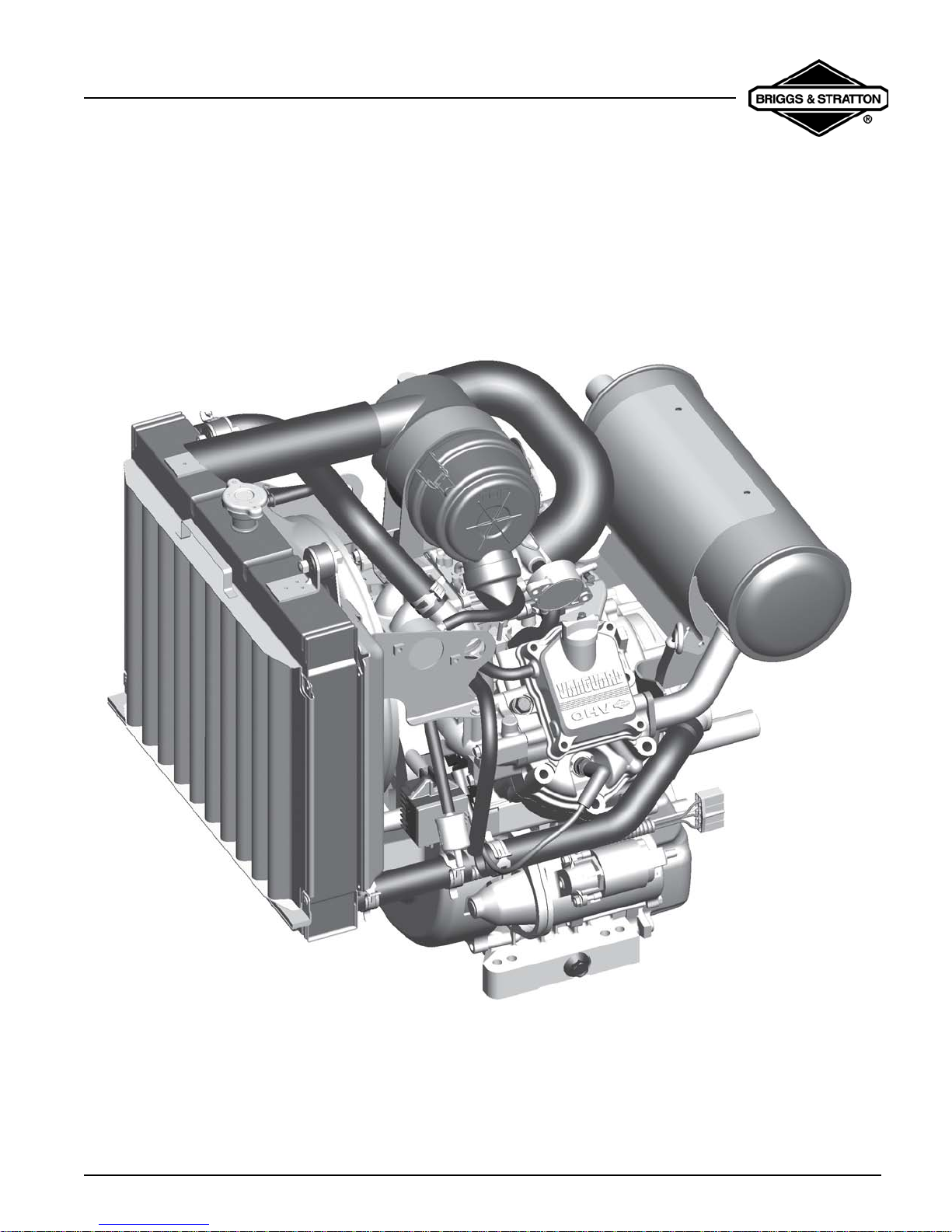
VanguardTM Twin-Cylinder OHV Liquid-Cooled Engine
MODEL 473100
2 CYLINDER LIQUID COOLED ENGINE
COMMERCIAL POWER
MANUAL NUMBER: 275429
VanguardTM Twin-Cylinder OHV Liquid-Cooled Engine
SAFETY INFORMATION
The Briggs & Stratton engine is made of the finest
material in a state-of-the-art manufacturing facility.
Please understand that Briggs & Stratton sells engines
to original equipment manufacturers. It also sells to
others in the distribution chain who may sell to the
ultimate consumer, an equipment manufact urer, anot her
distributor or a dealer. As a result, Briggs & Stratton does
not necessarily know the application on which the engin e
will be placed. For that reason, carefully read and
understand the operating instructions of the equipment
before you repair or operate.
You should also understand that there are equipment
applications for which Briggs & Stratton does not
approve the use of its engines. Briggs & Stratton e ngines
are not to be used on vehicles with less than 4 wheels.
This includes motor bikes, aircraft products and all
terrain vehicles. Moreover, Briggs & Stratton does not
approve of its engines being used in competitive events.
FOR THAT REASON, BRIGGS & STRATTON
ENGINES ARE NOT AUTHORIZED FOR ANY OF
THESE APPLICATIONS. Failure to follow this warning
could result in death, serious injury (including paralysis)
or property damage.
• Prior to work, read and understand the section(s) of
this manual that pertain to the job. Follow all safety
warnings.
• Wear suitable eye protection.
• Prevent accedental starting by removing spark plug
wire from spark plug when servicing engine or
equipment. Disconnect negative battery terminal if
equipped with electric starting system.
• Periodically clean engine . K eep go v ernor parts free
of dirt, grass and other debris which can affect
engine speed.
• Always use fresh gasoline. Stale fuel can gum
carburetor and cause leakage.
• Check fuel lines and fittings frequently for cracks or
leaks and replace if necessary.
IN THE INTEREST OF SAFETY
The safety alert symbol ( ) is used to identify safety
information about hazards that can result in personal
injury.
A signal word (
with the alert symbol to indicate the likelihood and the
potential severity of injury. In addition, a hazard symbol
may be used to represent the type of hazard.
DANGER indicates a hazard which, if not
avoided,
WARNING indicates a hazard which, if not
avoided,
CAUTION indicates a hazard which, if not
avoided, might result in minor or moderate injury.
CAUTION: When this signal word is used without the
alert symbol, it indicates a situation that could result in
damage to the engine.
DANGER, WARNING, or CAUTION) is used
will result in death or serious injury.
could result in death or serious injury.
VanguardTM Twin-Cylinder OHV Liquid-Cooled Engine
VanguardTM Twin-Cylinder OHV Liquid-Cooled Engine

VanguardTM Twin-Cylinder OHV Liquid-Cooled Engine
Table Of Contents
MODEL 473100
2 CYLINDER LIQUID COOLED ENGINE
COMMERCIAL POWER . ... ... ....... ... ... .... ... ... ... .... ... . 1
SAFETY INFORMATION ....................................... 2
IN THE INTEREST OF SAFETY...................... 2
SECTION 1
GENERAL INFORMATION ............................ .... ....3
ENGINE IDENTIFICATION ................ ...... .... ... . 4
MAINTENANCE SCHEDULE ...........................5
FUEL AND OIL RECOMENDATIONS ..............6
CHANGING OIL AND OIL FILTER................... 7
CHANGE COOLANT .......................... ... ... .... ... . 7
CLEANING DEBRIS .................... .... ... ..............8
ADJUST FAN BELT .........................................8
AIR CLEANER MAINTENANCE ...................... 8
REPLACE SPARK PLUG .................................9
CHARGING SYSTEM .....................................23
BATTERY INFORMATION .............................25
EQUIPMENT
AFFECTING ENGINE OPERATION ...............26
SECTION 3
ENGINE DISASSEMBLY ......................................27
GENERAL INFORMATION .............................27
REMOVE MUFFLER .......................................27
REMOVE RADIATOR .....................................27
DISCONNECT FUEL LINES ...........................28
REMOVE FAN ASSEMBLY ............................28
REMOVE CARBURETOR ..............................29
REMOVE STARTER .......................................30
REMOVE INTAKE MANIFOLD .......................31
REMOVE ALTERNATOR ...............................32
REMOVE CYLINDER HEADS ........................32
SECTION 2
TROUBLESHOOTING ......................................... 11
GENERAL INFORMATION ............................ 11
WILL NOT START ..........................................11
STARTER CURRENT DRAW TEST ..............12
NO LOAD
STARTER CURRENT DRAW TEST ..............13
CHECK CARBURETION ................................ 16
FUEL SHUT-OFF SOLENOID ........................ 16
FUEL PUMP - GENERAL INFORMATION .... 17
CYLINDER BALANCE TEST .........................18
CYLINDER LEAKDOWN TEST ......................19
CHECKING COOLING SYSTEM ...................21
CHECK OIL PRESSURE SWITCH ................22
CHECK OIL PRESSURE ...............................23
REMOVE CRANKCASE COVER ...................33
REMOVE CAMSHAFT ....................................34
REMOVE PISTONS, RODS, CRANKSHAFT .34
SECTION 4
ENGINE OVERHAUL ............................................35
CHECK CYLINDER ........................................35
BEARINGS ......................................................37
CRANKSHAFT ............................ .................... 38
PISTON, RINGS AND CONNECTING ROD
DISASSEMBLY AND INSPECTION ...............38
CYLINDER HEAD
INSPECTION AND REPAIR ...........................41
OIL PUMP .......................................................44
REPLACING WATER PUMP SEAL ................45
REPLACING STARTER SOLENOID ..............46
Page 1

VanguardTM Twin-Cylinder OHV Liquid-Cooled Engine
Table Of Contents
REPLACING PINION GEAR ASSEMBLY ......47
CARBURETOR INSPECTION AND REPAIR .51
SECTION 5
ENGINE ASSEMBLY ............................................57
INSTALL CRANKSHAFT ................................57
ASSEMBLE
PISTON AND CONNECTING ROD ................57
ASSEMBLE PISTON RINGS TO PISTON .....57
INSTALL
PISTON AND CONNECTING ROD ................58
INSTALL CAMSHAFT ....................................59
INSTALL GOVERNOR GEAR ........................59
INSTALL CRANKCASE COVER ....................59
INSTALL STARTER .......................................60
INSTALL ALTERNATOR ................................60
SECTION 6
FINAL ADJUSTMENTS AND
SPECIFICATIONS ................................................ 71
GENERAL INFORMATION ............................ 71
REMOTE GOVERNOR CONTROLS.............. 71
CARBURETOR ADJUSTMENT ..................... 72
MODEL 473100 SPECIFICATIONS ............... 75
ENGINE HARNESS ....................................... 77
INSTALL FLYWHEEL .....................................61
INSTALL CYLINDER HEADS .........................61
INSTALL ROCKER ARMS .............................61
ADJUST VALVE CLEARANCE ......................62
INSTALL ARMATURES ..................................62
INSTALL FAN ASSEMBLY .............................63
INSTALL INTAKE MANIFOLD ........................64
INSTALL CARBURETOR AND INTAKE ELBOW
ASSEMBLY ....................................................64
ADJUST GOVERNOR ....................................66
INSTALL MUFFLER .......................................66
INSTALL RADIATOR ......................................67
INSTALL AIR CLEANER ASSEMBLY ............67
Page 2

VanguardTM Twin-Cylinder OHV Liquid-Cooled Engine
Section 1 - General Information
SECTION 1 GENERAL INFORMATION
BRIGGS & STRATTON NUMERICAL IDENTIFICATION SYSTEM
This chart explains the unique Briggs & Stratton numerical model designation system. It is possible to determine most of the important
mechanical features of the engine by merely knowing the model number. Here is how it works:
• A. The first one or two digits indicate the approximate CUBIC INCH DISPLACEMENT.
• B. The first digit after the displacement indicates the BASIC DESIGN SERIES, relating to cylinder construction, ignition, general
configuration, etc.
• C. The second digit after the displacement indicates ORIENTATION OF CRANKSHAFT.
• D. The third digit after the displacement indicates TYPE OF BEARINGS, and whether or not the engine is equipped with
REDUCTION GEAR or AUXILIARY DRIVE.
• E. The last digit indicates the TYPE OF STARTER.
BRIGGS & STRATTON MODEL NUMBERING SYSTEM
Third Digit
After Displalcement
D
PTO Bearing
Reduction Gear,
A
Cubic Inch
Displacement
First Digit
After Displalcement
B
Basic
Design Series
Second Digit
After Displalcement
C
Crankshaft
Orientation
Auxiliary Drive,
Lubrication
0 -
6
8
9
10
11
12
13
16
18
19
20
21
22
23
24
25
28
29
30
31
32
35
38
40
42
43
44
46
47
52
54
58
Example - To Identify Model 303447:
30
30 Cubic Inch
TYPE 1234-01 The type number identifies the engine mechanical parts, color of paint, decals, goverened speed and original Equipment Manufacturer.
Code 01061201 The code is the manufacturing dat and is read as follows:
Year
01
MONTH
06
0
1
2
3
4
5
6
7
8
9
A to Z
3
Design Series 3
DAY
12
0 to 4 - Horizantal Shaft
5 to 9 - Verticle Shaft
A to G - Horizantal Shaft
H to z - Verticle Shaft
4
Horizantal Shaft
ASSEMBLY LINE AND MANUFACTURING PLANT
Plain Bearing/DU
Non-Flange Mount
1 -
Plain Bearing
Flange Mount
Sleeve Bearing
2 -
Flange Mounting
Splash Lube
Ball Bearing
3 -
Flange Mounting
Splash Lube
Ball Bearing
4 -
Flange Mounting
Pressure Lubrication
5 -
Plain Bearing
Gear Reduction
(6-1) CCW Rotation
Flange Mounting
Plain Bearing
6 -
Gear Reduction
(2-1) CCW Rotation
Plain Bearing
7 -
Pressure Lubrication
8 -
Plain Bearing
Auxiliary Drive (PTO)
Perpendicular to
Crankshaft
9 -
Plain Bearing
Auxiliary Drive (PTO)
Parallel to
Crankshaft
A -
Plain Bearing
Pressure Lubrication
Without Oil Filter
4
Horizantal Shaft
Flange Mounting
Pressure Lubrication
Fourth Digit
After Displalcement
Type of
Starter
0 -
Without Starter
Rope Starter
1 -
Rewind Starter
2 3 -
Electric Starter Only
110 or 230 Volt Gear
Drive
4 -
Electric Starter/110
or 230 Volt Gear
Drive with Alternator
5 -
Electric Starter Only
12 or 24 Volt Gear
Drive
Alternator Only
6 7 -
Electric Starter 12 or
24 Volt Gear Drive
with Alternator
Verticle Pull Starter
8 -
or Side Pull Starter
9 -
Mechanical Starter
A -
Electric Starter 12 or
24 Volt Gear Drive
with Alternator and
Inverter
Electric Starter
12 or 24 Volt Gear Drive
with Alternator
E
7
Page 3
ENGINE IDENTIFICATION
VanguardTM Twin-Cylinder OHV Liquid-Cooled Engine
Section 1 - General Information
Oil Fill Cap
Dipstick
Spark Plug
12V Electric Starter
Oil Drain Plug
Fan Belt (If Equipped)
Fuel Filter
Radiator Drain Plug (If Equipped)
Radiator Screen & Handle (If Equipped)
Radiator & Radiator Cap (If Equipped)
Air Cleaner (If Equipped)
Fig. 1
Fuel Pump
Muffler (If Equipped)
Choke Control
Throttle Control (2 Possible Locations)
Radiator Reservoir (If Equipped)
Oil Filter
Oil Drip Tray (Igf Equipped)
Oil Pressure Switch
Engine Model Label
MODEL TYPE
xxxxxx
xxxx xx
CODE
xxxxxxxx
Page 4
VanguardTM Twin-Cylinder OHV Liquid-Cooled Engine
Section 1 - General Information
MAINTENANCE SCHEDULE
Daily 50 Hours 100 Hours 250 Hours 600 Hours Yearly
Check Oil
Level
Check For Oil
Leaks
Change Oil
Change Oil
Filter
Check
Coolant
Change
Coolant
Check Fan
Belt
Clean Air
Filter
Replace Air
Filter
Check Valve
Clearance
Check
Battery
Electrolyte
X
X
X*
X*
X X***
X
X**
X**
X
X
Change
Spark Plugs
Change Fuel
Filter
Clean Spark
arrestor
Change oil after first 50 hours of use, then every
*
100 hours or every season. Change oil every 50
hours when operating the engine under heavy load orin
high temperatures.
Clean more often under dusty conditions or when
**
airborne debris is present. Replace air cleaner
parts, if very dirty.
X
X
X
If an extended life coolant is used, interval may be
***
increased to once every 3000 hours.
Page 5
FUEL AND OIL RECOMENDATIONS
Gasoline
Use clean, fresh, unleaded gasoline. Leaded gasoline
may be used if unleaded is not available. A minimum of
85 octane is recommended. The use of unleaded
gasoline results in fewer combustion deposits and longer
valve life.
We do not recommend the use of gasoline that con tains
alcohol, such as gasohol. However, if used, it must not
contain more than 10 percent Ethanol and must be
removed from the engine during storage. Do not use
gasoline that contains Methanol.
Only purchase a 30-day supply of gasoline. Fresh
gasoline minimizes gum deposits and also will ensure
fuel volatility tailored for the season in which the engine
will be operated.
NOTE: The use of a fuel additive, such as
Briggs & Stratton Gasoline Additive
equivalent, will minimize the formation of fuel
gum deposits during storage. Such an additive
may be added to the fuel tank or storag e
container.
Lubrication
Oil has four purposes. It cools, cleans, seals and
lubricates. During normal operation, small particles of
metal from the cylinder walls, pistons, bearings and
combustion deposits will gradually contaminate the oil.
Dust particles from the air also contaminate the oil
forming an abrasive mixture which can cause wear to all
of the internal moving parts of the engine, if the oil is not
changed regularly. Fresh oil also assists in cooling. Old
oil gradually becomes thick and loses its cooling ability
as well as its lubricating qualities.
Oil Recommendations
Use a high quality detergent oil classified “For Service
SF, SG, SH, SJ” or higher. Briggs & Stratton strongly
recommends the use of synthetic oil such as Briggs &
Stratton
(#100074) or equivalent. If synthetic oil is not
available, Briggs & Stratton non-synthetic 30 weight oil
(#100005 or #100028) is an acceptable substitute. No
special additives should be used with recommended oils.
Do not mix oil with gasoline.
(#5041) or
VanguardTM Twin-Cylinder OHV Liquid-Cooled Engine
Section 1 - General Information
SAE Viscosity Grades
CAUTION: The use of non-synthetic multi-
viscosity oils (5W-30, 10W-30, etc.) in
temperatures above 405°F (45°C) will result in
higher than normal oil consumption. When using
a multi-viscosity oil, check oil level more
frequently.
SAE 30 oil, if used below 405°F (45°C), will
result in hard starting and possible engine bore
damage due to inadequate lubrication.
Lubrication System
Briggs & Stratton Vanguard™ liquid cooled OHV VTwins use a full pressure lubrication system with an oil
filter. The gear driven oil pump draws oil from a screened
oil pickup and pumps the oil through the oil filter.
The filtered oil flows through oil galleries in the cylinder
and crankcase cover and is distributed through the
crankshaft to the main bearings and connecting rod
bearings. Engine oil pressure will vary with oil viscosity,
ambient air temperature differences, ope ra tin g
temperatures and engine load. Follow the oil
recommendation shown above.
Oil Pressure - @ 705° F (215° C): 10 ~ 50 psi
(0.7 ~ 3.5 Bar)
A pressure relief valve limits the maximum oil pressure in
the system.
The engine may be equipped with an oil pressure switch
which may be used to activate a warning device if oil
pressure drops below approximately 8 psi (.55 Bar). The
warning device is supplied by the equipment
manufacturer.
Page 6
VanguardTM Twin-Cylinder OHV Liquid-Cooled Engine
Section 1 - General Information
CHANGING OIL AND OIL FILTER
Change oil and filter after first fifty (50) hours of
operation.
Thereafter, change oil and filter every one hund red (100)
hours of operation. Change oil more often if engine is
operated in dirty or dusty conditions or if engine is
operated under heavy loads or in high ambient air
temperatures.
Oil Capacity: Approximately 87 oz. (2.6 liters) with filter.
Place equipment so that engine is level.
1. Remove oil drain plug and drain oil while engine is
still warm.
2. Install and torque drain plug to 20 ft. lbs. (27 Nm).
3. Remove oil filter and clean mounting surface.
4. Lightly oil new filter gasket with engine oil.
5. Screw filter on by hand until gasket contacts oil
filter adapter. Tighten 1/2 to 3/4 turn more.
6. Clean area around oil fill cap, then remove oil fill
cap and add 67 ounces (2 liters) of oil.
7. Start and run engine at idle for 60 se conds. Th en,
shut engine off and wait 60 seconds.
8. Add more oil slowly to bring oil level to
on dipstick.
Do Not Overfill.
FULL mark
9. Replace oil fill cap and dipstick.
10. Start and run engine to check for oil leaks.
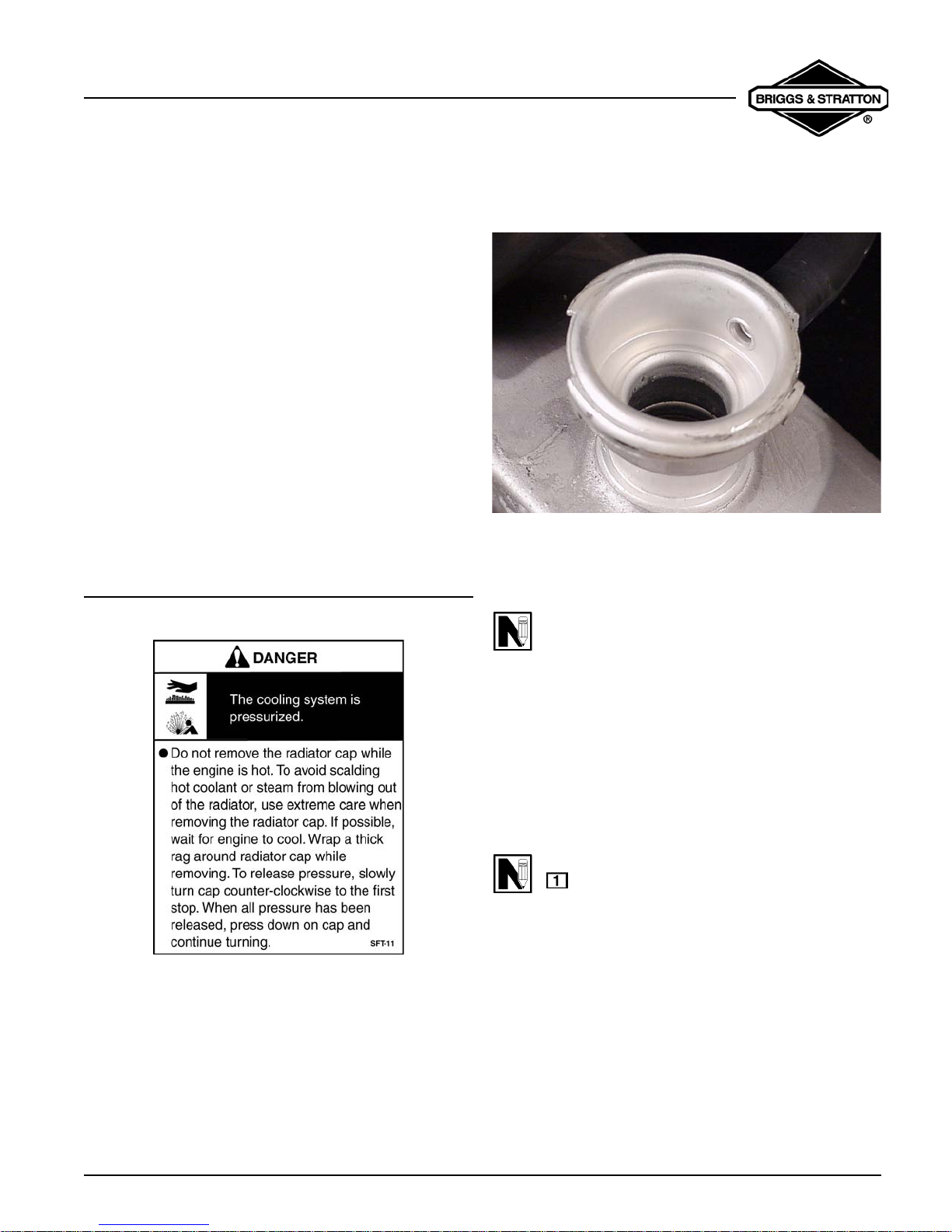
CHANGE COOLANT
Coolant should be replaced every year, unless an
approved extended life coolant is used. Then replace
every 3000 hours.
NOTE: A 50/50 mixture of phosphate-free
antifreeze and tap water is required for proper
heat dissipation, rust resistance and lubrication.
Fig. 2
NOTE: Overfilling can cause a smoking or
overheating condition due oil foaming.
Oil Filter
OIL DRAIN PLUG
OIL FILL
DIP STICK
FULL
CAUTION: Used coolant is a hazardous waste
product. Dispose of used coolant properly.
Check with your local authorities, service center,
or dealer for safe disposal/recycling facilities.
1. Remove drain plug. As coolant is running out,
open radiator cap to allow any trapped coolant to
drain. Replace drain plug.
2. Remove reservoir bottle, drain it and reinstall.
3. Fill radiator to bottom of filler neck and between
FULL and LOW in reservoir. Replace radiator cap.
4. Start and run engine for 30 seconds.
5. Shut engine off and allow it to cool. Recheck
coolant levels in radiator and reservoir.
6. Coolant level in reservoir bottle should be
between
FULL and LOW when engine is cold.
Page 7
VanguardTM Twin-Cylinder OHV Liquid-Cooled Engine
Section 1 - General Information
Normal coolant temperature gauge (if equipped) should
read between 175° and 195° F (80° and 90° C) when
engine is running.
If coolant temperature rises above 220° F (105° C), the
temperature light (if equipped) will illuminate. Idle engine
down for a while. Then stop engine. Once engine is
cooled, check coolant level, fan belt tension and clogged
radiator fins.
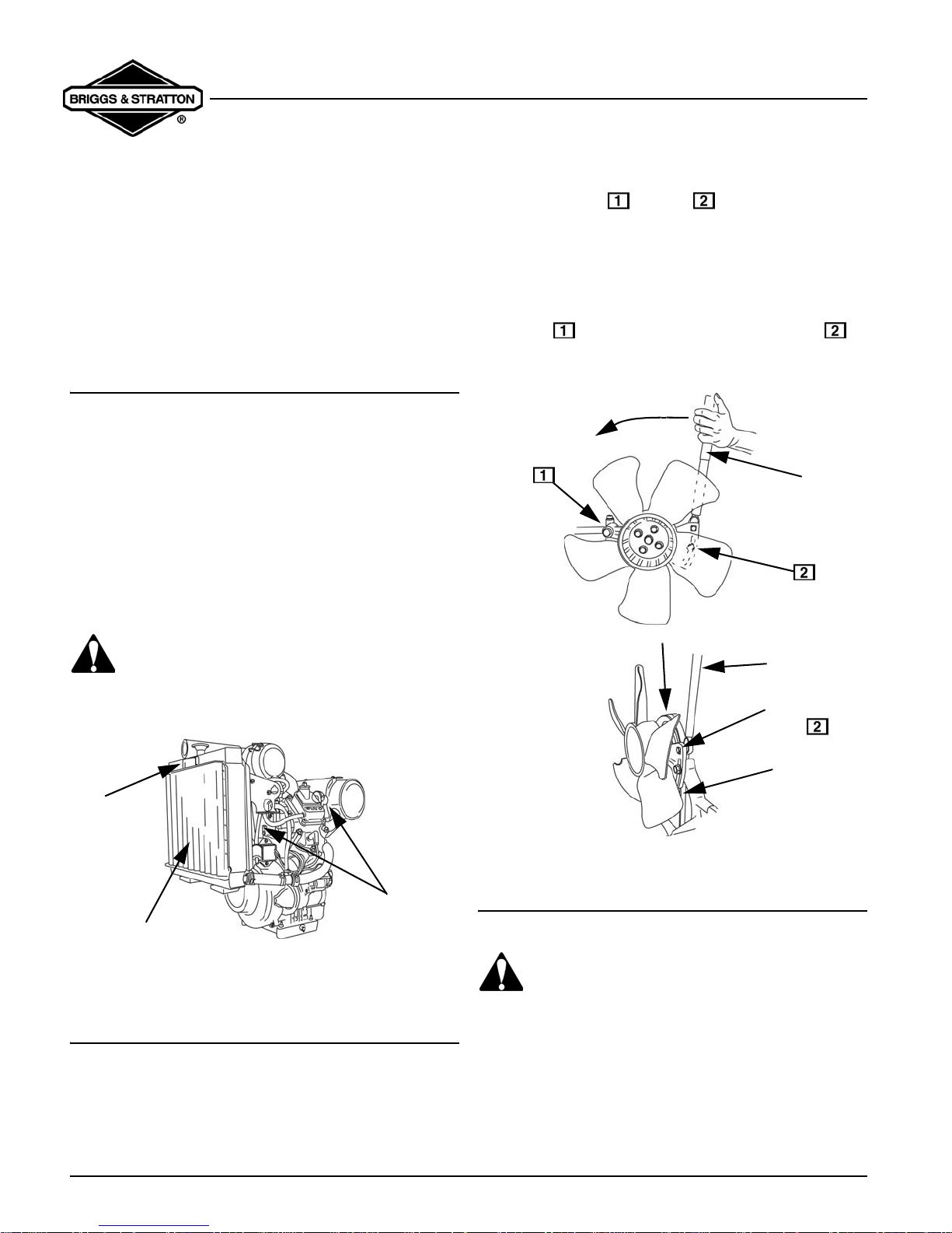
CLEANING DEBRIS
Daily or before every use, clean accumulated debris
from engine. Keep linkage, springs and controls clean.
Keep area around and behind muffler free of any
combustible debris.
Use the handle on the radiator screen to lift off for
cleaning. Clean screen thoroughly and clean radiator
fins.
Do not use water to clean engine parts. Water could
contaminate fuel system. Low pressure compressed air
may be used. Be careful not to damage radiator fins.
CAUTION: Engine parts should be kept clean
to reduce the risk of overheating and ignition of
accumulated debris
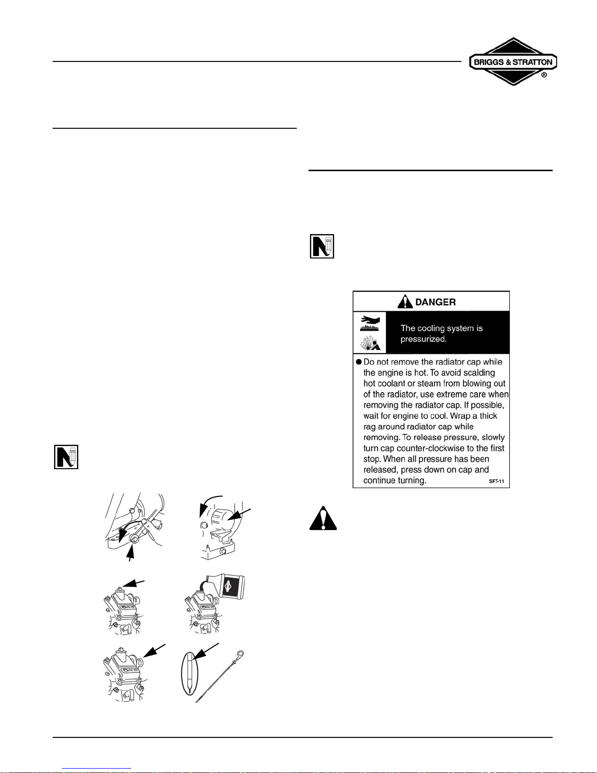
1. Loosen bolt and bolt .
2. Fit torque wrench in t he square hole located in the
bracket.
3. Apply 115 in. lbs. of torque in the direction of the
arrow.
4. While belt is being tensioned per step 3, torque
bolt to 125 in. lbs. (14 Nm). Torque bolt to
110 in. lbs. (12 Nm).
TORQUE
WRENCH
FAN BELT
TORQUE
WRENCH
SQUARE
TORQUE
HOLE
RADIATOR
HANDLE
CLEAN DEBRIS
Fig. 3
ADJUST FAN BELT
• Check condition of fan belt.
• Replace if damaged or worn.
To Adjust Fan Belt Tension
Page 8
CLEAN
DEBRIS
FAN BELT
Fig. 4
AIR CLEANER MAINTENANCE
WARNING: Never operate engine with air
cleaner assembly or air cleaner cartridge
removed.
A properly serviced air cleaner protects internal parts of
the engine from dirt and dust particles in the air. If air
cleaner instructions are not carefully followed, dirt and
dust which should be collected in the cleaner will be
drawn into the engine. These particles are highly
abrasive and will cause the piston rings and cylinder
VanguardTM Twin-Cylinder OHV Liquid-Cooled Engine
Section 1 - General Information
bore to wear quickly. As the rings and cylinder bore
become worn, these abrasive particles enter the
crankcase and contaminate the oil, forming an abrasive
mixture which will cause wear on all of the internal
moving parts.
Clean cartridge every 100 hours. To clean cartridge,
gently tap on end with handle of screwdriver. Replace
cartridge every 600 hours. Clean and replace more ofte n
under dusty conditions. Replace if very dirty or any
damage occurs to cartridge.
NOTE: Do not use pressurized air or solvents to
clean cartridge. Pressurized air can damage
cartridge; solvents will dissolve cartridge.
1. Unlock clamps and remove cover .
2. Remove cartridge from air cleaner body.
3. Carefully clean out air cleaner cover.
4. Install cartridge in body.
5. Install cover and lock clamps with rubber valve
down.
REPLACE SPARK PLUG
Replace spark plugs every year. Replace spark plugs if
electrodes are burned away, or the p orcel ain is cracked.
Set spark plug gap at .020” (.51 mm). Torque spark
plugs to 180 in. lbs. (20.0 Nm).
B&S to Champion*
Plug Type
Resistor Plug
Resistor Plug
Champion and the Bow Tie are trademarks of Federal-Mogul Ignition
*
Co. Used under license.
NOTE: Do not blast clean spark plugs. Spark
plugs should be cleaned by scraping or hand
wire brushing and washing in a commercial
solvent.
B&S Champion*
491055 RC12YC
496018 RC14YC
Fig.5
Fig. 6
Page 9
VanguardTM Twin-Cylinder OHV Liquid-Cooled Engine
Section 1 - General Information
Page 10
VanguardTM Twin-Cylinder OHV Liquid-Cooled Engine
Section 2 - Troubleshooting
SECTION 2
TROUBLESHOOTING
GENERAL INFORMATION
Most complaints concerning engine operation can be
classified as one or a combination of the following:
1. Will not start
2. Hard Starting
3. Lack of power
4. Runs Rough
5. Vibration
6. Overheating
7. High Oil Consumption
NOTE: What appears to be an engine
malfunction may be a fault of the powered
equipment rather than the engine. If equipment
is suspect, see Equipment Affecting Engine
Operation.
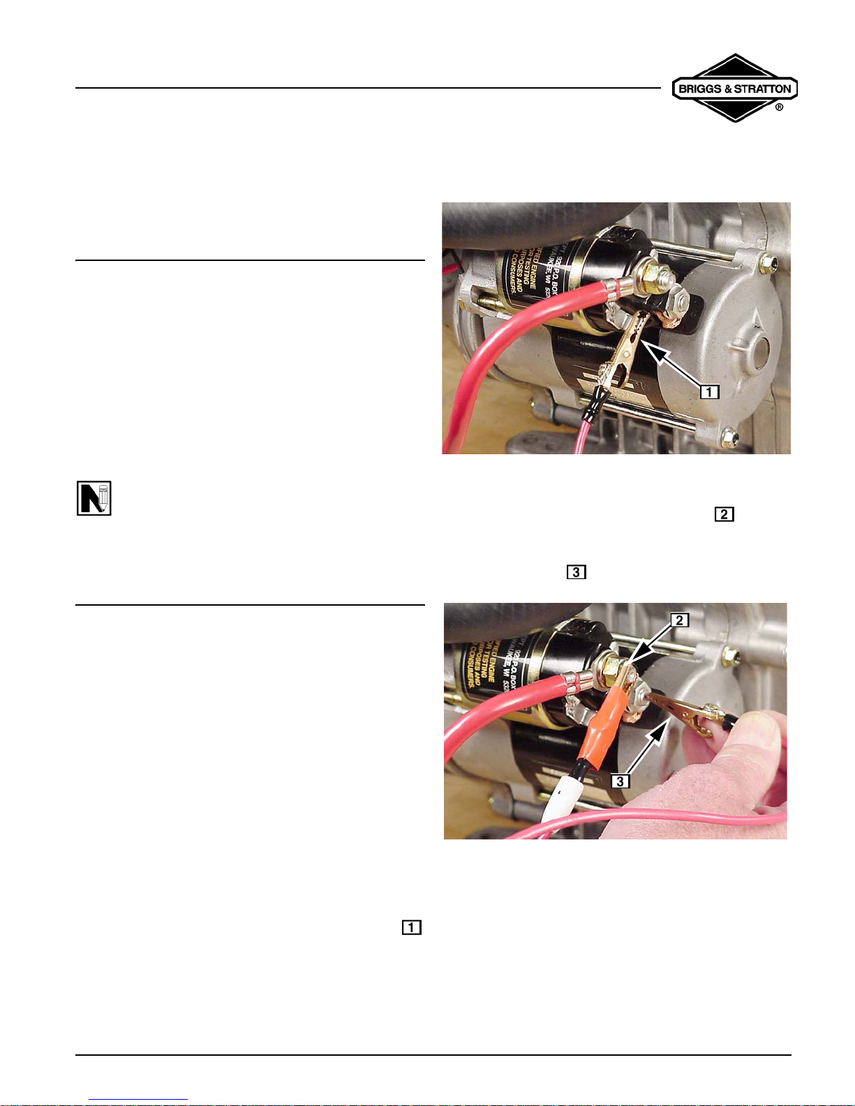
WILL NOT START
3. If starter cranks, there is a problem with the key
switch or wiring.
Fig. 7
4. If starter does not crank, remove jumper wire from
battery and attach to battery terminal on
solenoid.
5. With other end of jumper wire, make contact to the
field terminal on solenoid, Fig. 8.
Engine Will Not Turn Over
1. Make sure that safety equipment installed by the
Original Equipment Manufacturer (OEM) is
functioning properly and is not preventing the
engine from cranking. Remove any parasitic load
on engine (drive unit disengaged).
2. Make sure battery cables and solenoid
connections are clean and tight.
3. Check battery voltage from positive battery
terminal to battery terminal on solenoid.
Voltage must not be below 11.7 volts.
Check Starter
A jumper wire is required for the next test.
1. Disconnect wire at tab terminal on solenoid.
2. Attach one end of jumper wire to positive terminal
on battery. Then, make contact to tab termin al
on solenoid, Fig. 7.
Fig. 8
6. If starter turns over, the solenoid is defective.
Replace solenoid.
If starter does not turn over, the starter motor is
defective. Replace starter motor.
Engine Turns Over Slowly
If engine turns over slowly, but will not start, first refer to
Will Not Start, steps 1 - 3. Then perform a starter current
draw test.
Page 11
VanguardTM Twin-Cylinder OHV Liquid-Cooled Engine
Section 2 - Troubleshooting
STARTER CURRENT DRAW TEST
IMPORTANT: When making the starter current draw
test make sure that all parasitic load is removed from the
engine and that engine has the correct viscosity oil.
Engine temperature should be at least 70°F (21°C).
Make sure battery and solenoid connections are clean
and tight.
NOTE: Battery voltage must not be below 11.7
volts.
Test Equipment
The following equipment is required to test current draw
of starter, Fig. 9.
5. A fully charged 12 volt battery.
Testing Starter
NOTE: To prevent engine from starting, remove
spark plug wires from spark plugs and ground
ignition using two Ignition Testers, Tool
Leave spark plugs installed.
The starter current draw test will be performed with the
meter in the
The DC Shunt must be installed on the negative (-)
terminal of the battery, Fig. 10.
300mV position.
#19368.
ATTACH NEGATIVE
BATTERY CABLE
3000mV
19464
19468
BATTERY
CABLES
JUMPER WIRES
Fig. 9
1. Digital multi-meter, Tool #19464.
2. DC shunt, Tool
3. Two battery cables with alligator clips.
4. One jumper wire with alligator clips.
Page 12
#19468.
Fig. 10
1. Attach RED meter test lead to RED post
terminal on shunt.
2. Attach
terminal on shunt.
3. Activate starter.
4. Current draw should not exceed 80 amps DC.
If amperage draw exceeds specification, remove starter
from engine and perform No Load starter current draw
test.
BLACK meter test lead to BLACK post
a. Allow 3 seconds for meter reading to stabilize.
VanguardTM Twin-Cylinder OHV Liquid-Cooled Engine
Section 2 - Troubleshooting
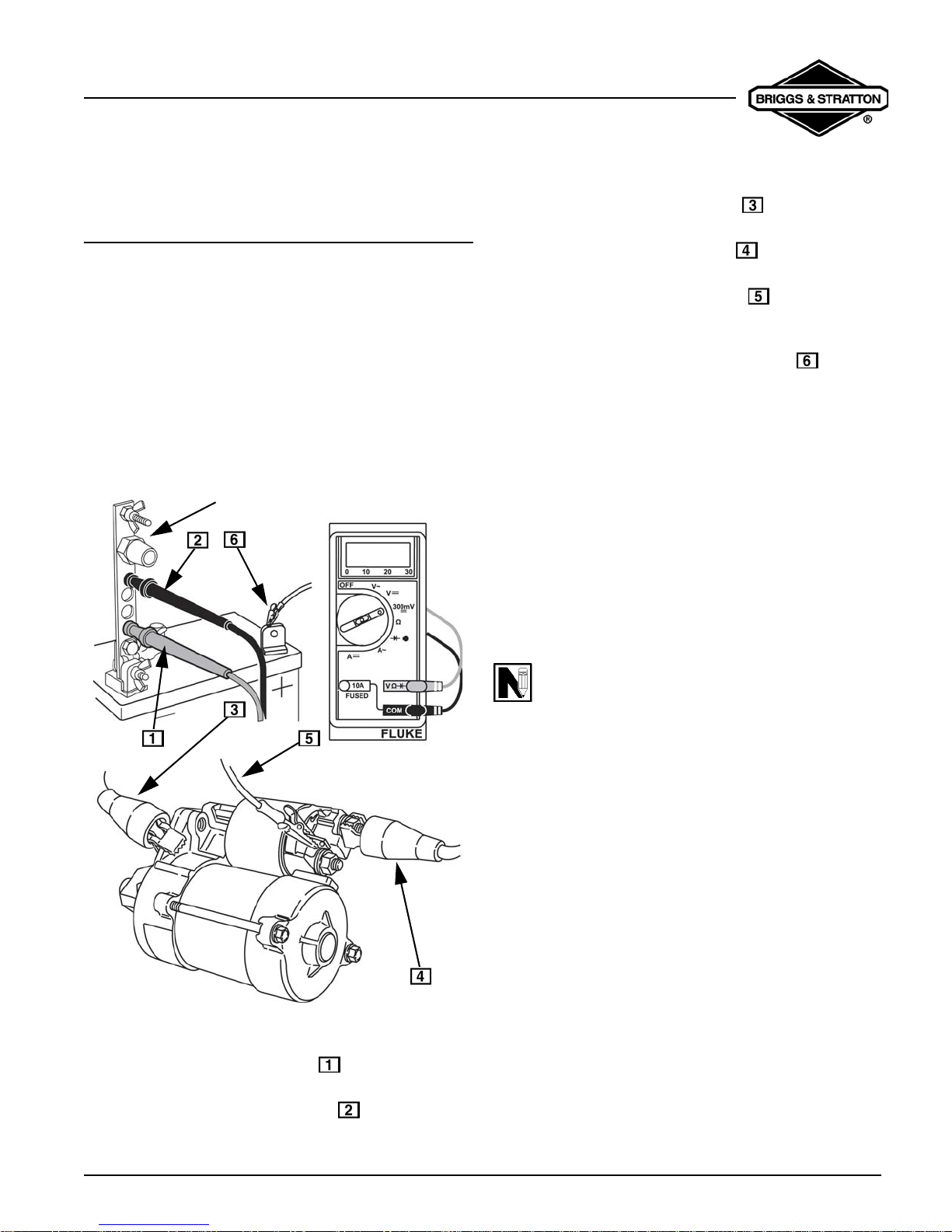
NO LOAD STARTER CURRENT DRAW
TEST
Remove starter motor.
To hold starter securely while testing, clamp starter
mounting bracket in a vise. DO NOT clamp starter
housing in a vise or field windings or magnets may be
damaged.
Testing Starter (No Load)
The No Load starter current draw test will be performed
with the meter in the
The DC Shunt must be installed on the negative (-)
terminal of the battery, Fig. 11.
300mV position.
ATTACH NEGATIVE
BATTERY CABLE
3. Attach negative battery cable to a good
ground such as drive housing.
4. Attach positive battery cable to battery
terminal on solenoid.
5. Attach one end of jumper wire to solenoid tab
terminal, Fig. 11.
6. Activate starter by contacting positive battery
terminal with other end of jumper wire , Fig. 11 .
a. Allow 3 seconds for meter reading to stabilize.
7. Current draw should not exceed 50 amps DC.
If amperage draw exceeds specification, replace
starter.
Hard Starting
Make sure the oil level is correct.
This engine is equipped with a “Low Oil Pressure
Sensor” and will not start if the oil level is too low.
Make sure drive unit is disengaged.
A loose drive belt like a loose blade can cause a
backlash effect, which will counteract engine cranking
effort.
Fig. 11
1. Attach RED meter test lead to RED post
terminal on shunt.
2. Attach
terminal on shunt.
BLACK meter test lead to BLACK post
NOTE: Magnetron® ignition system requires a
minimum of 350 RPM before it will produce a
spark.
Systematic Check
If the engine is hard starting or will not start and the
cause of malfunction is not readily apparent, perform a
systematic check in the following order:
1. Ignition
2. Carburetion
3. Compression
This check-up, performed in a systematic manner, can
usually be done in a matter of minutes. It is the quickest
and surest method of determining the cause of failure.
Page 13

VanguardTM Twin-Cylinder OHV Liquid-Cooled Engine
Section 2 - Troubleshooting
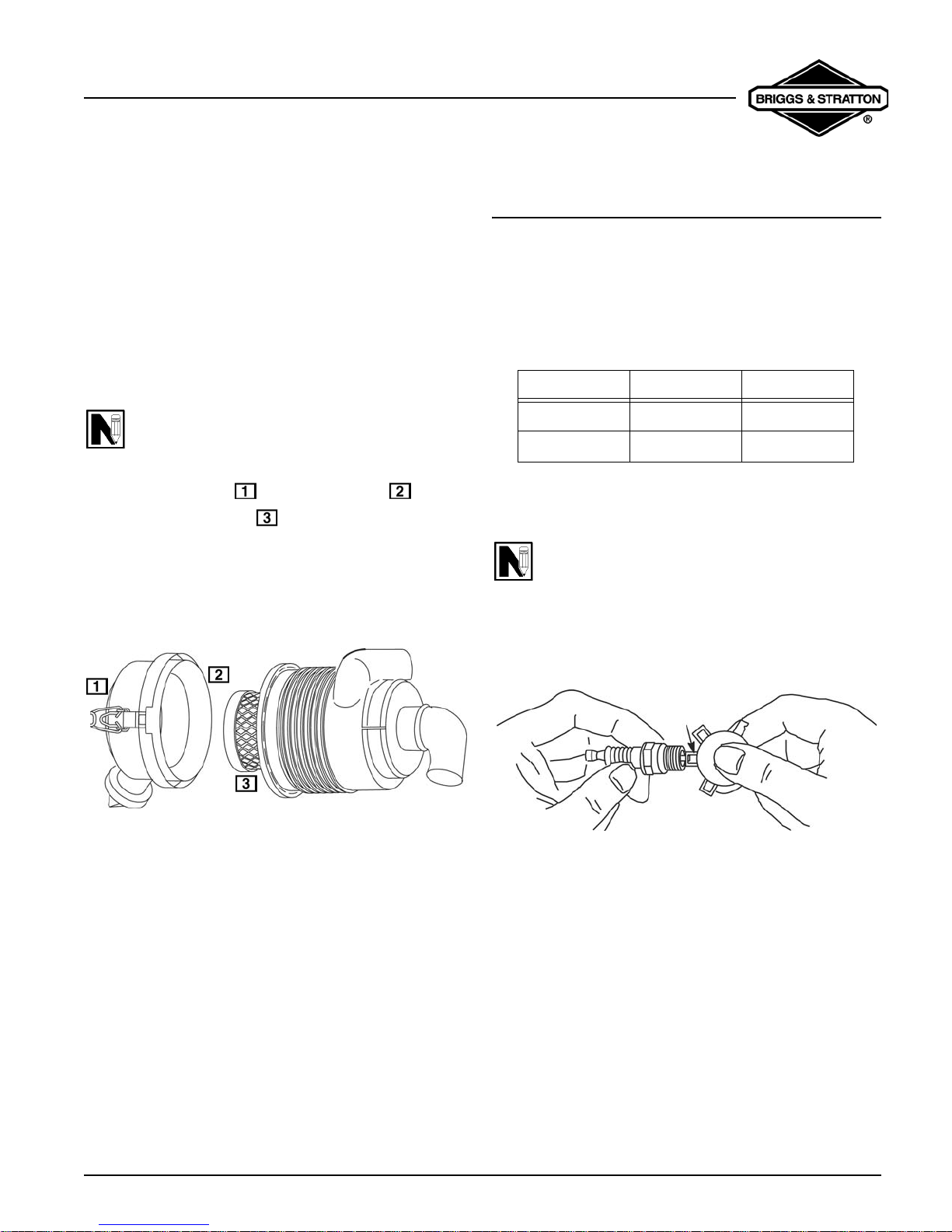
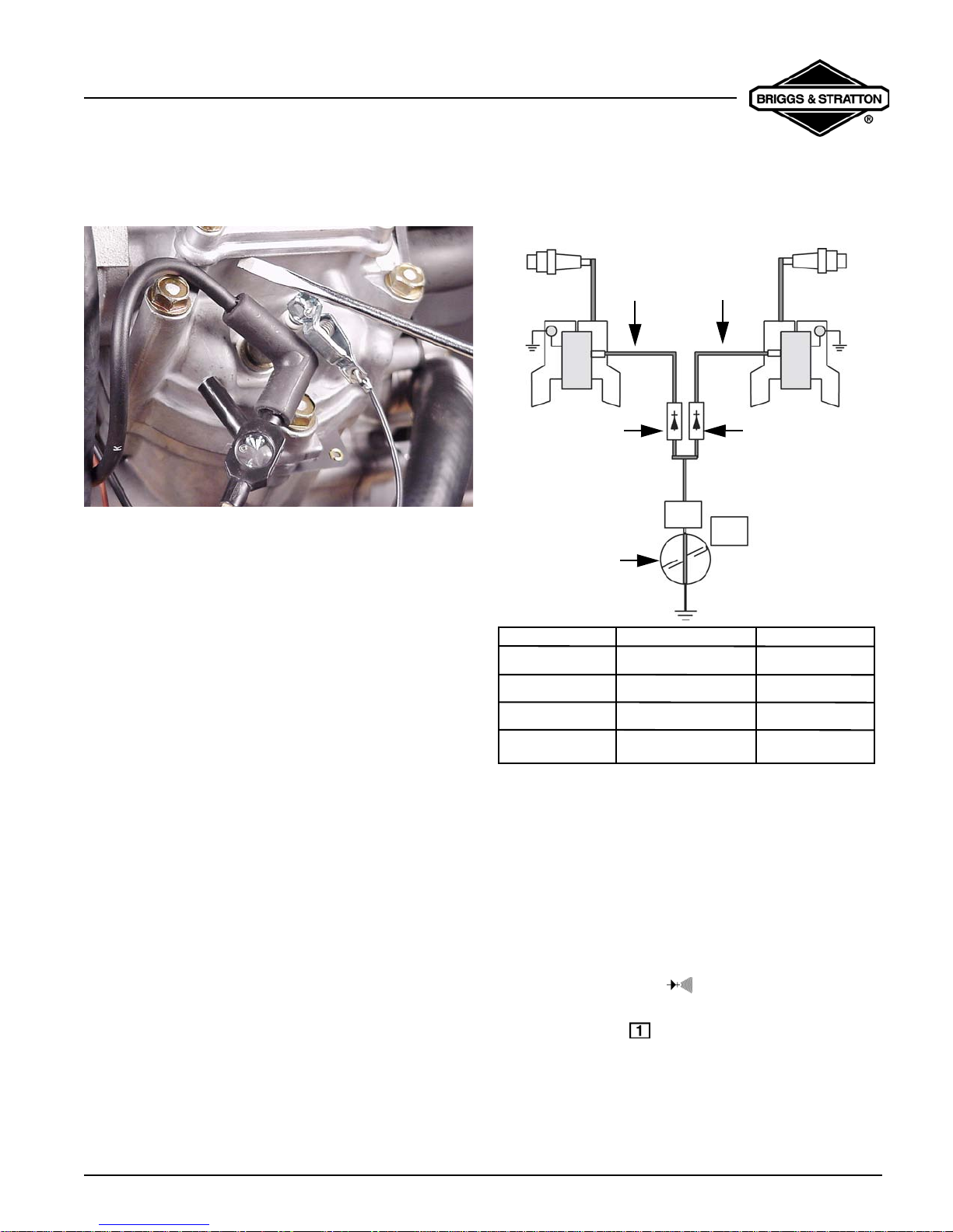
Check Ignition (With Engine Starter)
With spark plugs installed, attach a
#19368 ignition tester
to each spark plug lead and ground the other end of the
tester as shown in Fig.12. Activate the electric starter. If
spark jumps the tester gaps, you may assume the
ignition system is functioning satisfactorily.
Fig. 12
NOTE: Engines equipped with Magnetron®
ignition system will still display spark at tester
with a partially or fully sheared flywheel key. A
partially sheared flywheel key will affect ignition
timing and engine performance.
Check Ignition (Engine Running)
If engine runs but misses during operatio n, a quick check
to determine if ignition is or is not at fault can be made by
installing Tool
#19368 tester between the spark plug lead
and each spark plug, Fig.13. A spark miss will be readily
apparent when the engine is running. If sp ark is good but
engine misses, check for a fouled spark plug.
Fig. 13
Check Ignition (Fouled Plug or Other Causes)
To check for a fouled spark plug or a non-functioning
cylinder, attach Tool
plug lead and each spark plug. With engine running at
top no load speed, ground one spark plug, Fig. 14. The
engine should continue to run on the other cylinder.
Repeat this test with the other cylinder. If the engine will
not continue to run when making this test, the cylinder
that is NOT grounded is not functioning and/or the spark
plug is fouled. Install a new spark plug before
proceeding. When replacing spark plugs always use
Briggs & Stratton
#19368 tester between the spark
#491055 or #496018.
If spark does not occur look for:
1. Improperly operating interlock system
2. Shorted equipment stop switch wire
3. Two closed diodes in ground wire harness (see:
Troubleshooting Ground Wire Harness)
4. Incorrect armature air gap
5. Armature failure
Page 14
VanguardTM Twin-Cylinder OHV Liquid-Cooled Engine
Section 2 - Troubleshooting
Fig. 14
If miss continues:
The problem may be carburetion or compression relat ed.
See Check Carburetion and/or Cylinder Balance Test
and Cylinder Leakdown Test.
Troubleshooting Ground Wire Harness
The ground wire harness contains two diodes. If a diode
fails “open,” the cylinder with the open diode will continue
to run when the equipment key switch is turned off. If a
diode fails “short,” the cylinder with the shorted diode will
not run (no spark).
Refer to Failure Diagnosis Table for symptoms.
Testing Ground Wire Harness
The Digital Multimeter, Tool
test the ground wires. The following test will be made
with the meter in the “Diode Test Position”.
#19464 is recommended to
DIODE FAILURE DIAGNOSTIC TABLE
Ground Wire Harness
DiodeDiode
OFF
ON
Equipment
Switch
SWITCH ON
Engine runs on one
cylinder.
Engine runs.
(Both Cylinders)
Won’t Run
(No Spark)
Engine runs.
(Both Cylinders)
SWITCH OFF CAUSE
Shuts Off OK
Only one cylinder shuts Off
Engine won’t shut Off
1 Closed Diode
1 Open Diode
2 Closed Diodes
2 Open Diodes
Fig. 15
In the Diode Test position, the meter will display the
forward voltage drop across the diode(s). If the voltage
drop is less than 0.7 volts, the meter will “Beep” once as
well as display the voltage drop. A continuous tone
indicates continuity (shorted diode). An incomplete
circuit (open diode) will be displayed as “OL.”
1. Insert
2. Insert
3. Rotate selector to (Diode Test) position.
4. Insert
5. Touch
RED test lead into receptacle in meter.
BLACK test lead into receptacle in meter.
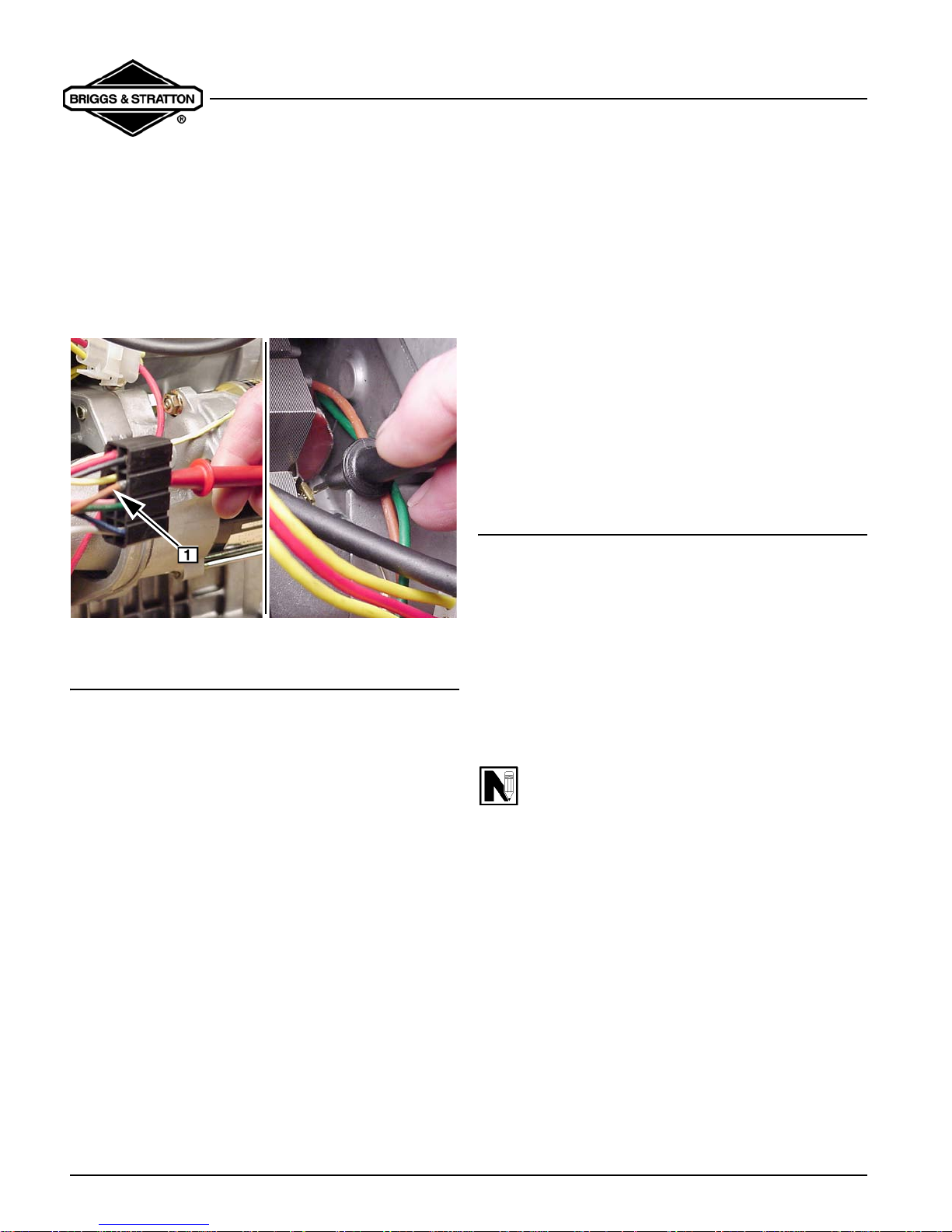
RED test lead into ground wire terminal
(brown wire) receptacle in engine harness,
Fig. 16. Leave attached for remainder of test.
BLACK test lead probe to ground wire tab
terminal on ignition coil for #2 cylinder.
Page 15
VanguardTM Twin-Cylinder OHV Liquid-Cooled Engine
Section 2 - Troubleshooting
If meter “Beeps” once, diode is OK.
If meter makes a continuous tone, diode is defective
(shorted). Replace ground harness.
If meter displays “OL,” diode is defective (open). Replace
ground harness.
6. Now, repeat test for #1 cylinder. Results must be
the same.
Fig. 16
CHECK CARBURETION
Before making a carburetion check, be sure the fuel tank
has an ample supply of fresh, clean gasoline. Be sure
that the shutoff valve, if equipped, is op en an d fu el f lows
freely through the fuel line before star ting engine.
If fuel fails to flow or is slow check for plugged fuel cap
vent, fuel line restriction or plugged fuel filter.
Make sure throttle and choke controls are properly
adjusted.
If engine cranks but will not start, remove and inspect the
spark plugs.
If plugs are wet, look for:
1. Over choking
2. Excessively rich fuel mixture
3. Water in fuel
4. Float needle valve stuck open
5. Plugged air cleaner
6. Fouled spark plugs
If plugs are dry, look for:
1. Leaking carburetor or intake manifo ld mounting
gaskets
2. Gummy or dirty carburetor, fuel filter, fuel lines or
fuel tank
3. Float needle valve stuck shut
4. Inoperative fuel pump
5. Inoperative fuel shut off solenoid
A simple check to determine if the fuel is getting to the
combustion chamber through the carburetor is to remove
either spark plug and pour a small quantity of gasoline
through the spark plug hole. Replace the plug. If the
engine fires a few times and then stops, look for the
same conditions as for a dry plug.
FUEL SHUT-OFF SOLENOID
The fuel shut off solenoid is controlled by the equipment
ignition switch. When the equipment switch is in the
position, the solenoid valve plunger closes, stopping fuel
flow through the fixed main and idle jets. When the
switch is in the
ON and START position, the solenoid
valve opens, allowing normal fuel flow. The solenoid is
operating properly if a click is heard when equipment
ignition switch is turned
ON and OFF. If solenoid is not
working (defective solenoid or equipment wiring), the
engine will not start or run.
NOTE: Fuel shut off solenoid requires a
minimum of 9 volts DC to function.
Testing Solenoid
If solenoid does not click, the problem may be in
equipment wiring, engine wiring harness or solenoid. To
determine whether problem is with wiring or solenoid,
perform the following tests in the order shown.
Test Equipment
The digital multimeter,
solenoid equipment wiring.
The following tests will be performed with the meter in
the (DC volts) position.
Tool #19464 is required to test the
OFF
Page 16

VanguardTM Twin-Cylinder OHV Liquid-Cooled Engine
Section 2 - Troubleshooting
Testing Equipment Wiring
1. With keyswitch in
solenoid wire (GRAY WIRE) from engine wiring
harness connector (WHITE WIRE).
2. Insert red meter test lead into equipment side of
wiring harness connector (WHITE WIRE) , Fig.
17.
3. Attach black test lead to a good ground .
4. Turn keyswitch to
a.Meter should display battery voltage at
connector.
OFF position, disconnect
ON position.
Fig. 17
4. If solenoid does not “click”, it is defective. Replace.
Fig. 18
FUEL PUMP - GENERAL INFORMATION
The fuel pump, mounted on the No. 1 cylinder fan
bracket, allows remote fuel tank installations. The fuel
pump will prime at
pressure is
pulsating crankcase vacuum from the engine. The
vacuum pulse line is installed on the No. 1 cylinder valve
cover, Fig. 19.
1.5 psi (0.1 Bar). The pump is operated by
12” (30.5 cm) maximum lift. Fuel pump
If meter does not display battery voltage, problem is
with wiring harness. Check for loose or broken
wire.
If meter displays battery voltage, test engine wiring
harness.
Testing Solenoid
A pair of jumper wires and a 9 volt transistor battery are
required for this test.
1. Attach one jumper wire to solenoid wire
(GRAY WIRE) and positive terminal on battery
, Fig. 18.
2. Attach second jumper wire to negative terminal on
battery and a good ground .
3. Solenoid should “click”.
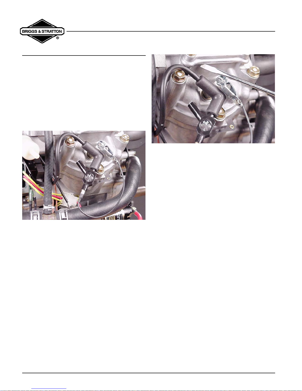
Fig. 19
NOTE: An air leak at the fuel pump pulse line
hose connections will result in improper fuel
flow.The fuel pump is available as an assembly
only.
Replace fuel lines and vacuum pulse line if stiff and
brittle.
Page 17
CYLINDER BALANCE TEST
If the engine is hard starting, runs rough, misses or lacks
power, perform a cylinder balance test to determine
whether both cylinders are operating to their full
potential.
Tools Required
1. Tachometer,
2. Two #19368 Ignition Testers
3. Screwdriver with insulated handle
Attach ignition tester,
plug lead and each spark plug, Fig. 20.
Tool #19200 or 19389
Tool #19368 between the spark
VanguardTM Twin-Cylinder OHV Liquid-Cooled Engine
Section 2 - Troubleshooting
Fig. 21
Things Which Affect Both Cylinders
1. Carburetion
2. Crankcase vacuum
3. Ignition timing
a. A partially sheared flywheel key will affect
ignition timing and engine performanc e.
If the RPM loss is greater than 75 RPM this indicates that
the cylinder with the least RPM loss is the weaker of the
two cylinders. Look to that cylinder for a problem.
Fig. 20
Start and run engine running at top no load speed and
note spark at ignition testers. If the spa rk is equal at both
ignition testers, the problem is not ignition related. A
spark miss will be readily apparent. Now note RPM of
engine. Ground out one cylinder with screwdriver by
contacting alligator clip on ignition tester and a good
ground on engine, Fig. 21. Note RPM loss. Then ground
out the other spark plug and note the RPM loss. If the
difference between the two cylinders does not exce ed 75
RPM, the amount of work the two cylinders are doing
should be considered equal.
Example:
Engine RPM - Both Cylinders = 3400 RPM
Engine RPM - #1 Cylinder Grounded = 3300 RPM
Engine RPM - #2 Cylinder Grounded = 3100 RPM
Conclusion: #1 cylinder is the weaker of the two cylinders.
Things Which Affect One Cylinder
1. Spark plug
a. A fouled spark plug may indicate that
carburetor is out of adjustment.
2. Leak in spark plug wire
3. Head gasket
4. Intake manifold
a. A leak at either end of the intake manifold will
only affect one cylinder, not both.
5. Valves
6. Rings
7. Piston
8. Cylinder
The cylinder balance test will also detect a cylinder that
is not functioning. When grounding out one cylinder
Page 18
VanguardTM Twin-Cylinder OHV Liquid-Cooled Engine
Section 2 - Troubleshooting
there will be no RPM loss. When the other cylinder is
grounded out the engine will stop.
NOTE: A twin cylinder engine will run well on
one cylinder as long as the power required for
the application does not exceed the power
produced by the one cylinder.
CYLINDER LEAKDOWN TEST
An accurate method of checking the sealing capability of
the compression components is by using the cylinder
leakdown tester
show any variation between cylinders as well as identify
which components may be at fault.
A regulated amount of compressed air is used to
pressurize the combustion chamber with the piston at
TDC on the compression stroke. By listening for air
leaks, it is possible to isolate a specific component or
components causing a problem. An engine in good
condition will display a reading in the green area on the
outlet gauge with a minimum of audible leakage. A
reading in the yellow or red area along with high audible
leakage indicates a problem with the compression
components.
A small amount of air leakage is normal in all engines,
including new engines, providing that the outlet gauge
remains in the green area.
However, if a single component is displaying more
audible leakage, look to that component for a potential
problem. For example, frequently a slight air leak at the
head gasket may not register on the gauge. Ob viously
the head gasket would require replacement, as any leak
at the head gasket would have an adverse affect on
engine performance.
NOTE: When testing water cooled engines,
always remove the radiator cap. If air bubbles
are observed in the coolant while the combustion
chamber is pressurized, this indicates that the
head gasket is leaking internally and/or the
cylinder head or block is cracked.
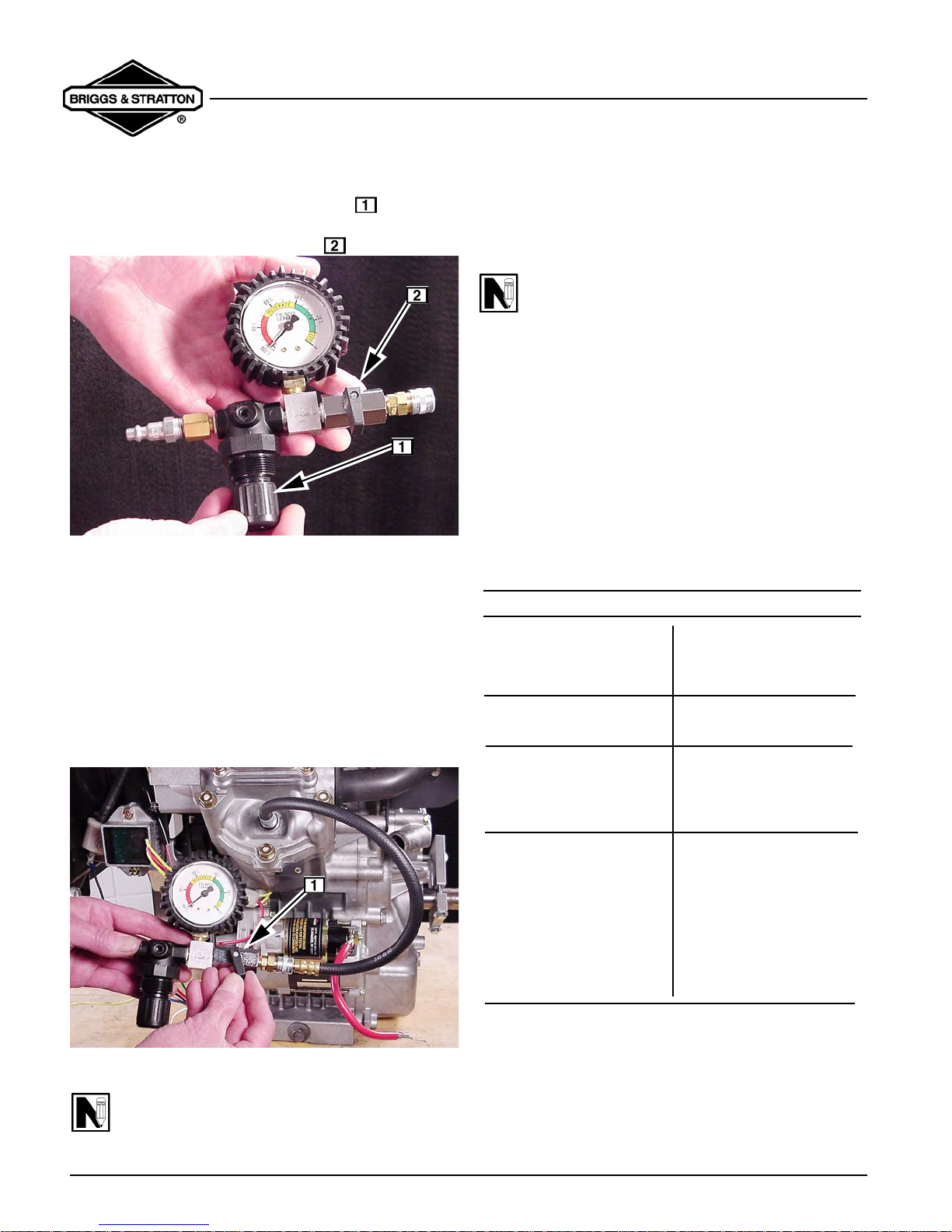
Tool# 19545. The leakdown test will
because compression components are not at normal
operating temperatures.
2. Remove spark plugs from engine. Disconnect air
cleaner tube and crankcase breather tube at
carburetor intake elbow.
3. Rotate crankshaft in direction of operation until
piston for cylinder being tested is at top dead
center of compression stroke.
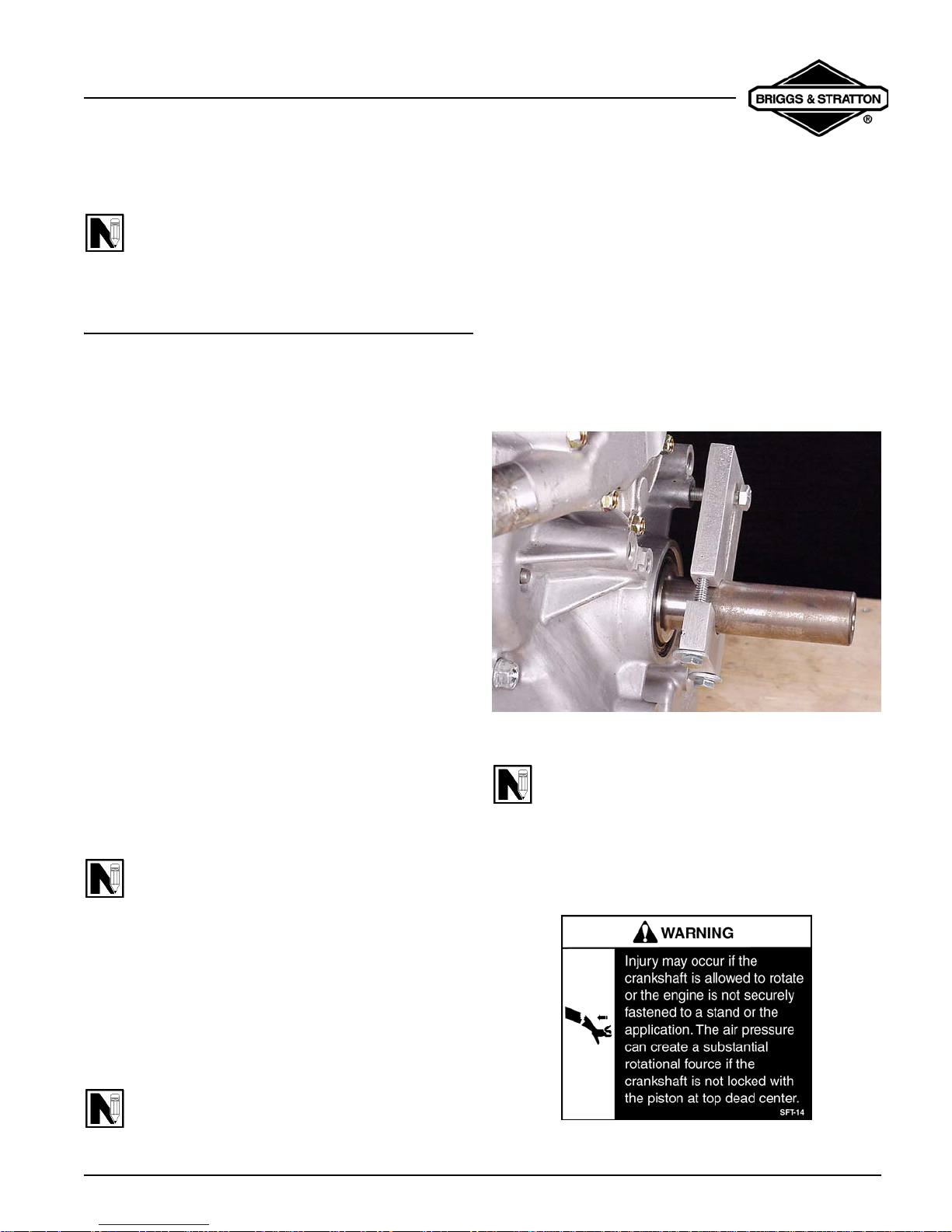
4. Assemble the clamping tool to the crankshaft.
Torque screws to
3/8” breaker bar into slot of clamp or install screw
through slot into bolt circle hole in crankcase
cover, Fig. 22.
150 in. lbs. Insert drive end of a
Fig. 22
NOTE: The crankshaft must be held with the
piston at top dead center to seal the combustion
chamber and eliminate any chance of rotation. If
the engine is installed in an application, many
times the equipment can positively lock the
crankshaft from moving.
Compression Testing Using Leakdown Tester, Tool
#19545
1. Run engine for 5 minutes allowing engine to reach
operating temperature.
NOTE: If engine is cold or cann ot b e st art ed, air
flow may be higher (gauge readings lower)
Page 19
VanguardTM Twin-Cylinder OHV Liquid-Cooled Engine
Section 2 - Troubleshooting
5. Pull the regulator adjustment knob out and
turn knob counterclockwise as far as it will go, Fig.
23. Make sure air outlet valve is closed.
Fig. 23
6. Connect the tester to the shop air source
(minimum air pressure of 70 psi).
7. Install the outlet hose into the spark plug hole of
the cylinder being tested. Be sure “O” Ring is
seated to prevent air leak at spark plug hole.
Connect other end to tester.
8. Turn regulator adjustment knob clockwise until the
tester’s needle is on the set point. Push knob in t o
lock. Slowly open air outlet valve and note
position of needle on gauge, Fig. 24.
9. Listen for air leaking from the cylinder head
gasket, carburetor, exhaust system and the
crankcase breather tube.
NOTE: If a high flow of air is leaking from the
exhaust and carburetor, make sure the pi ston is
at TDC on the compression stroke.
a. Air flowing between the cylinder and cylinder
head indicates that the cylinder head gasket is
leaking.
b. Air flowing from the carburetor indicates air is
leaking past the intake valve and seat.
c. Air flowing from the exhaust system indicates
air is leaking past the exhaust valve and seat.
d. Air flowing from the crankcase breather tube
or high oil fill dipstick tube indicates air is
leaking past the piston rings.
COMPRESSION TEST RESULTS
Reading is Green. A small
amount of air is leaking
from head gasket.
Reading is Green.
Minimum air leakage.
Reading is Yellow/Red or
Red, and all the air is
leaking from one
component.
Replace head gasket, and
re-test.
Look for problems tat are
not compression related.
Look for a possible
problem with that
component.
Fig. 24
NOTE: Any air leaks at the connections or
fittings of the tester will affect the accuracy of the
test.
Page 20
Reading is Red, and air is
leaking from several
components.
Check that piston is at
TDC on the compression
stroke. If reading does
not change, look for
problems beginning with
the component that
appeared to leak the
most air. Re-test after
repair.
10. When test is complete, close air valve. Then, pull
out knob and turn counterclockwise as far as it will
go to release pressure in combustion chamber.
VanguardTM Twin-Cylinder OHV Liquid-Cooled Engine
Section 2 - Troubleshooting
11. Disconnect outlet hose from tester before
removing from spark plug hole.
12. Repeat test for other cylinder.
The variation between the two cylinders should be less
than 20%. If the difference is greater than 20%, check
the cylinder with the lower reading.
Possible Causes for Poor Compression:
1. Loose cylinder head bolts
2. Blown head gasket
3. Burned valves, valve seats and/or loose valve
seats
4. Insufficient tappet clearance
5. Warped cylinder head
6. Warped valve stems
7. Worn bore and/or rings
8. Broken connecting rods
CHECKING COOLING SYSTEM
a. Coolant level must be no more than 1 in. (.25
mm) below bottom of filler neck.
Fig. 25
2. Install cooling system pressure tester on radiator
and pressurize system to
NOTE: System must maintain pressure during
test.
15 psi (1.03 Bar).
Pressure Testing Cooling System
1. Remove radiator cap and make sure coolant is at
correct level, Fig. 25.
3. Check the following for any signs of leaking.
a. Hoses and connections (also check hoses for
excessive bulging)
b. Radiator
c. Water pump
d. Telltale hole in crankcase cover
e. Intake manifold and by-pass hose
f. Cylinder block and cylinder head
NOTE: If coolant is evident at the telltale hole
in the crankcase cover, Fig. 26, this is an
indication that the water pump seal in the
crankcase cover is leaking, which may cause
coolant to enter the crankcase and contaminate
the oil. Severe engine damage could occur.
Page 21
 Loading...