

Page 1

I-TRIM
OWNER'S MANUAL
Includes Specifications, Assembly, Operation,
Maintenance & Parts Lists
NA TIONAL MOWER CO.
MARCH 2006
700 Raymond Ave., P.O. Box 14299, St. Paul, Minnesota 55114-0299, U.S.A.
Phone (651) 646-4079 – Fax (651) 646-2887
www.nationalmower.com
Page 2

2
Page 3

TABLE OF CONTENTS
Table of contents...................................................... 3
Introduction............................................................... 4
Safe Operating Practices ...................................... 4-6
Decal (Transfer) Identification............................... 7-9
Introduction and Receipt of Shipment ................... 10
1— Specifications ................................................... 11
2— Assembly Instructions...................................... 12
3—General Information .......................................... 15
4—Controls............................................................. 16
5—Operation .......................................................... 18
6—Adjustments ...................................................... 20
I-TRIM
®
7—Maintenance ....................................................... 22
8—Storage................................................................ 28
9—Troubleshooting .................................................. 29
Wiring Diagram.........................................................33
Maintenance Record.................................................34
10—Parts Ordering Information ............................... 35
Screen box, guards, ROPS................... 36-37
Deck Lift Arms and Pull Arms............... 38-39
Seat, Wheels, Engine, Radiator, tank 340-41
Wheel Motors, Filters, Hyd Comp. ....... 42-43
Pedal Assy, Hyd Pumps ....................... 44-45
Front Axle, Fuel Tank, Frame ............... 46-47
Engine and Radiator Assembly ................. 48
Rear Mower Deck Assembly...................... 49
Right Mower Deck Assembly..................... 50
Left Mower Deck Assembly ....................... 51
Hydraulics- Deck Motors/Oil Cooler ..... 52-53
Hydraulics - Wheel Motors/Steering..... 54-55
Electrical System Components...................56
Steering Cylinder........................................57
Hydraulic Schematic - Steering/Drive.......................58
Hydraulic Schematic - Mower Drives/Deck Lift.........59
Warrenty...................................................................61
Appendix 1- Briggs & Stratton Operating Instructions
3
Page 4

INTRODUCTION
Read this manual carefully to learn how to operate and
maintain your product properly. The information in this
manual can help you and others avoid injury and product
damage. The operator is responsible for operating this
product properly and safely.
This manual identifies potential hazards and has special
safety messages that help you and avoid personal injury and
even death. Danger, Warning, and Caution are signal words
used to identify the level of hazard. Howerver, regardless of
the hazard, be extremely careful.
Danger signals an extreme hazard that will cause series
injury or death if you do not follow the recommended
precautions.
Warning signals a hazard that may cause serious injury or
death if you do not follow the recommended precautions.
Caution signals a hazard that may cause minor or moderate
injury if you do not follow the recommended precautions.
This manual uses two other words to highlight information.
Important call attention to special mechanical information
and Note: emphasizes general information worthy of special
attention.
• Keep in mind that the operator or user is responsible for
accidents or hazards occurring to other people or their
property.
• All drivers and mechanics should seek and obtain
professional and practical instruction. The owner is
responsible for training the users. Such instruction
should emphasize:
- the need for care and concentration when working with
ride-on machines;
- the owner/user can prevent and is responsible for
accidents or injuries occurring to himself or herself, other
people, or property;
- control of a ride-on machine sliding on a slope will not
be regained by the application of the brake or putting
transmission into neutral. Some reasons for loss of
control are: insufficient wheel grip, driving too fast,
inadequate braking, using a machine that is unsuitable
for a task, lack of awareness of the effect of ground
conditions (especially slopes), and incorrect load
distribution.
SAFETY
This machine meets or exceeds ANSI B71.4-1999 specifications in effect at the time of production.
Improper use or maintenance by the operator or owner can
result in injury. To reduce the potential for injury, comply with
these safety instructions and always pay attention to the
safety alert symbols: CAUTION, WARNING, and DANGER.
Failure to comply with the instruction may result in personal
injury or death.
Safe Operating Practices
The following instructions are from CEN standard EN
836:1997, ISO standard 5395: 1990, and ANSI B71.4-1999.
Training
• Read the Operator’s Manual and other training material
carefully. Be familiar with the controls, safety signs, and
the proper use of the equipment.
• Never allow children or people unfamiliar with these
instructions to use or service the mower. Local
regulations may restrict the age of the operator.
• Never mow while people, especially children, or pets are
nearby.
• Do not carry passengers.
Preparation
• Evaluate the terrain to determine what accessories and
attachments are needed to properly and safely perform
the job. Only use accessories and attachments approved
by the manufacturer.
• While mowing, always wear substantial footwear, long
trousers, hard hat, safety glasses, and ear protection.
Long hair, loose clothing, or jewelry may get tangled in
moving parts. Do not operate the equipment when
barefoot or wearing open sandals.
• Thoroughly inspect the area where the equipment is to
be used and remove all objects which may be thrown by
the machine.
• Check that operator’s presence controls, safety
switches, and shields are attached and functioning
properly. Do not operate unless they are functioning
properly.
• Warning - Fuel is highly flammable. Take the following
precautions:
- Store fuel in containers specifically designed for this
purpose.
- Refuel outdoors only and do not smoke while refuelling.
- Add fuel before starting the engine. Never remove the
cap of the fuel tank or add fuel while the engine is
running or when the engine is hot.
- If fuel is spilled, do not attempt to start the engine but
move the machine away from the area of spillage and
avoid creating any source of ignition until fuel vapors
have dissipated.
4
Page 5

Operation
• Do not operate the engine in a confined space where
dangerous carbon monoxide fumes can collect.
• Operate only in daylight or in good artificial light. Stay
alert for holes in the terrain and other hidden hazards.
• Before attempting to start the engine, disengage all
blade attachment clutches, shift into neutral, and engage
the parking brake. Only start the engine from the
operator’s position. Use seat belts if provided.
• Never operate with the discharge deflector raised,
removed, or altered, unless using a grass catcher.
I-TRIM
®
• Stop the engine and disengage drive to attachment
- before refuelling;
- before removing the grass catchers;
- before making height adjustment unless adjustment
can be made from the operator’s position.
- before clearing blockages;
- before checking, cleaning or working on the mower;
- after striking a foreign opject or if an abnormal vibration
occurs. Inspect the mower for damage and make repairs
before restarting and operating the equipment.
• Reduce the throttle setting before stopping engine and, if
the engine is provided with a shut-off valve, turn the fuel
off at the conclusion of mowing.
• Remember there is no such thing as a safe slope.
Travel on grass slopes requires particular care. To guard
against overturning:
- do not stop or start suddenly when going up or downhill.
- machine speeds should be kept low on slopes and
during tight turns.
- stay alert for humps and hollows and other hidden
hazards.
- never mow across the face of the slope, unless the
mower is designed for this purpose.
• Watch out for traffic when crossing or near roadways.
Slow down and use caution when making turns and
crossing roads and sidewalks. Stop the blade rotation
before crossing surfaces other than grass. Stop reels or
deck blades if not mowing.
• When using any attachments, never direct discharge of
material toward bystanders or allow anyone near the
machine while in operation.
• Never operate the machine with damaged guards,
shields, or without safety protective devices in place. Be
sure all interlocks are attached, adjusted properly, and
functioning properly.
• Keep hands and feet away from cutting units.
• Look behind and down before backing up to be sure of a
clear path.
• Do not operate the mower under the influence of alcohol
or drugs.
• Use care when loading or unloading the machine into a
trailer or truck.
• Use care when approaching blind corners, shrubs, trees,
or other objects that may obscure vision.
Maintenance and Storage
• Keep all nuts, bolts and screws tight to be sure the
equipment is in safe working condition. Replace all worn
or damaged decals.
• Never store the equipment with fuel in the tank inside a
building where fumes may reach an open flame or spark.
• Do not change the engine governor settings or
overspeed the engine. Operating the engine at
excessive speed may increase the hazard of personal
injury.
• Disengage drive to attachements when transporting or
not in use.
• Before leaving the operator’s position:
- stop on level ground;
- disengage the power take-off and blade rotation
and lower the attachments;
- Change into neutral and set the parking brake;
- stop the engine and remove the key.
• Keep hands and feet away from the cutting units.
• Allow the engine to cool before storing in any enclosure.
• To reduct the fire hazard, keep the engine, silencer,
battery compartment and fuel storage area free of grass,
leaves, or excessive grease.
• Park machine on level ground. Never allow untrained
personnel to service machine.
• Check the grass catcher frequently for wear or
deterioration.
• Keep all parts in good working condition and all
hardware and hydraulic fittings tightened.
• If the fuel tank has to be drained, do this outdoors.
• Shut off fuel while storing or transporting. Do not store
fuel near flames.
5
Page 6

• Be careful during adjustment of the machine to prevent
entrapment of the fingers between moving blades and
fixed parts of the machine Use care when checking
blades. Wrap the blade(s) or wear gloves, and use
caution when servicing them. Only replace blades.
Never straighten or weld them.
• On multi-reel or blade machines, take care as rotating
one blade can cause other blades to rotate.
• Disengage drives, lower the cutting units, set parking
brake and stop engine. Wait for all movement to stop
before adjusting, cleaning or repairing.
• Clean grass and debris from cutting units, drives,
mufflers, and engine to help prevent fires. Clean up oil or
fuel spillage.
• Check the safety interlock switches daily for proper
operation. If a switch should fail, replace the switch
before operating the machine.
• Using the machine demands attention. To prevent loss
of control:
- Do not drive close to sand traps, ditches, creeks, or
other hazards.
- Reduce speed when making sharp turns. Avoid sudden
stops and starts.
- When near or crossing roads, always yield the right-ofway.
- Reduce foward pedal movement when going downhill to
keep forward speed slow and to maintain control of the
machine.
• Use jack stands to support components when required.
• Carefully release pressure from components with stored
energy.
• Disconnect battery before making any repairs.
Disconnect the negative terminal first and the positive
last. Reconnect positive first and negative last.
• Keep hands and feet away from moving parts. If
possible, do not make adjustments with the engine
running.
• Charge batteries in an open well ventilated area, away
from spark and flames. Unplug charger before
connecting or disconnecting from battery. Wear
protective clothing and use insulated tools.
Other Riding Mower Safety Instructions
• Always follow all safety instructions to avoid serious
injury or death. This product is capable of amputating
hands and feet and throwing objects.
• Do not touch the engine, muffler, hydraulic components,
or exhaust pipe while the engine is running or soon after
it has stopped because these areas could be hot enough
to cause burns.
• Make sure all hydraulic line connectors are tight and all
hydraulic hoses and lines are in good condition before
applying pressure to the system.
• Keep your body and hands away from pin hole leaks or
nozzles that eject hydraulic fluid under high pressure.
Use paper or cardboard, not your hands, to search for
leaks. Hydraulic fluid escaping under pressure can have
sufficient force to penetrate the skin and cause serious
injury.
• Before disconnecting or performing any work on the
hydraulic sytem, all pressure in the system must be
relieved by stopping the engine and lowering the cutting
units and attachments to the ground.
• Know how to stop the engine quickly.
• Wearing safety shoes and long pants is advisable and
required by some local ordinances and insurance
regulations.
• The operator must be skilled and trained in how to drive
on hillsides. Failure to use caution on slopes or hills may
cause loss of control and cause the vehicle to tip or roll,
possible resulting in personal injury or death.
CALIFORNIA Proposition 65 Warning - Diesel engine
exhaust and some of its constituents are known to the State
of California to cause cancer, birth defects, and other
reproductive harm.
WARNING– California, USA residents are required by law (CA PRC 4442 & CA H & SC 13005) to equip their
engines with spark arresters when operating in flammable vegitation. Arresters must be obtained from your
engine dealer and are not available from National Mower Company.
6
IMPORTANT
Page 7

DECAL IDENTIFICATION
National has provided decals in many locations throughout
the machine to aid the operator in identifying, controlling
and operating the I-Trim safely and correctly. It is important
that all decals are clean and visable at all times. Replace
decals that are damaged, missing or accidently painted
over.
A
I-TRIM
®
B
D
E
C
7
Page 8

G
F
I
H
J
8
Page 9

K
I-TRIM
®
L
NAMES AND LOCATIONS
Item Part No. Description / Location
A 07792 I-Trim Model / Left and Right sides of operator panels
B 07794 Natinal Logo / Top of rear hood
C 07793 National Name / Front of steering column
D 07797 Diesel Fuel / Top of Fuel Tank
E 07796 Hydraulic Fluid / Top of hydraulic tank
F 07778 Warning light identification / Left side panel
G 07779 Key Switch and deck rotation switch / Right side panel
H 07777 Engine Speed / Left side panel
I 07411 Danger / Top of rear and wing mower decks
J 07780 Deck lift / Top of right operator panel
K 07795 Warning Decal / Top of steering column
L I-Trim Serial Number / Right side of steering column
M 08092 Instruction Decal- ANSI / steering column
M
9
Page 10

INTRODUCTION
This manual has been prepared by National Mower
Company as an aid to users for set up, operation and
servicing and ordering replacement parts. Additional
information will gladly be furnished by calling or writing
the company.
Please furnish us with the Model number, serial number
and date of purchase when contacting us about your
machine.
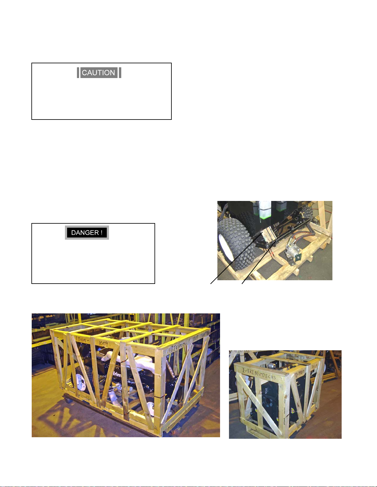
RECEIPT OF SHIPMENT
Carefully inspect your machine and crates for damage
that could have occured during shipment. If damages or
shortages are noted, have the transportation company’s
representative note this on the bill of lading.
10
Designations of right, left, front and rear are used in the
position of the operator sitting in the seat.
Metric equivalents are provided wherever possible for
users outside of the United States.
IMPORTANT
Claims for shipping damages must be noted by the
consignee at the point of designation and filed with
the transportation company.
Page 11

1—SPECIFICATIONS
1.1—ENGINE SPECIFICATIONS
TYPE: 3 cylinder turbocharged Diesel
ENGINE MODEL: Briggs & Stratton
954 DT
HORSEPOWER: 34 hp
I-TRIM
BATTERY TYPE: Exide Model 60 Premium
Type 78-60
12 V side post
7 3/16 (18 cm) height
6 ¾ (17 cm) width
10 1/4 (26 cm) length
®
1.5—CUTTING UNIT SPECIFICATIONS
COOLING: Water cooled
1.2—TRANSMISSION
TRACTION DRIVE:Oilgear variable
Displacement
Hydrostatic pump
WHEEL DRIVE Char Lynn hydraulic motors
MOTORS: with disc-parking brakes
1.3—STEERING
Eaton Power
Steering Control Unit
1.4—MOWER SPECIFICATIONS
FUEL TANK: 10 Gallons (38 liters)
CUTTING UNIT: (3) - 26” (.66m) wide decks
BLADES: (2) Right hand 26” (.66 m) wide blades
(1) Left hand 26” (.66m) wide blade
DECK MOTORS: (2) CW Hydraulic motors (Right/Rear)
(1) CCW Hydraulic motor (Left)
Rotation direction as viewed from top of deck
WIDTH OF CUT: 70” (1.778m)
HEIGHT OF CUT: 1.5” to 4” adjustment (38.1mm to
101.62mm)
1.6—LUBRICANTS
ENGINE OIL: Refer to enclosed Engine Manual
HYDRAULIC OIL: ISO 68 hydraulic grade oil.
1.7—OTHER
OIL TANK: 12 Gallons (45 liters) Approx.
TIRES: Front: 16 x 6.50 - 8 (28 psi max)
Rear: 23 x 10.50 x 12 (20 psi max)
FRAME: Welded steel construction
MOWING SPEED: 0 - 7 MPH (0 - 11.3 km)
CONTROLS: Foot operated traction pedal for forward
and reverse, hand operated throttle
conttrol, electric valve for cutting units,
and hand operated parking brake.
ROPS: Roll over protective structure
meets SAE J 1194 standards
11
Page 12
2—ASSEMBLY INSTRUCTIONS
2.1—TRACTOR ASSEMBLY
Handle banding material with caution. Use heavy
leather gloves. Banding is sharp!
The side and rear lift arms are spring-loaded up.
Take care when handeling.
1. Remove crating top, front and sides from the tractor crate.
Cut banding from Roll-Over Protective Structure (ROPS)
Fig A.
2. Cut banding from around tractor frame to crate base.
3. Unbolt rear deck motor from crate base and temporarily
strap to rear lift arm. Leave wood spacer in place on rear
lift arm to prevent damage.
3. Release parking brake and push or drive tractor off the
crate. See operating instructions. Do not engage deck
motors until tractor is fully assembled with decks. Reengage parking brake.
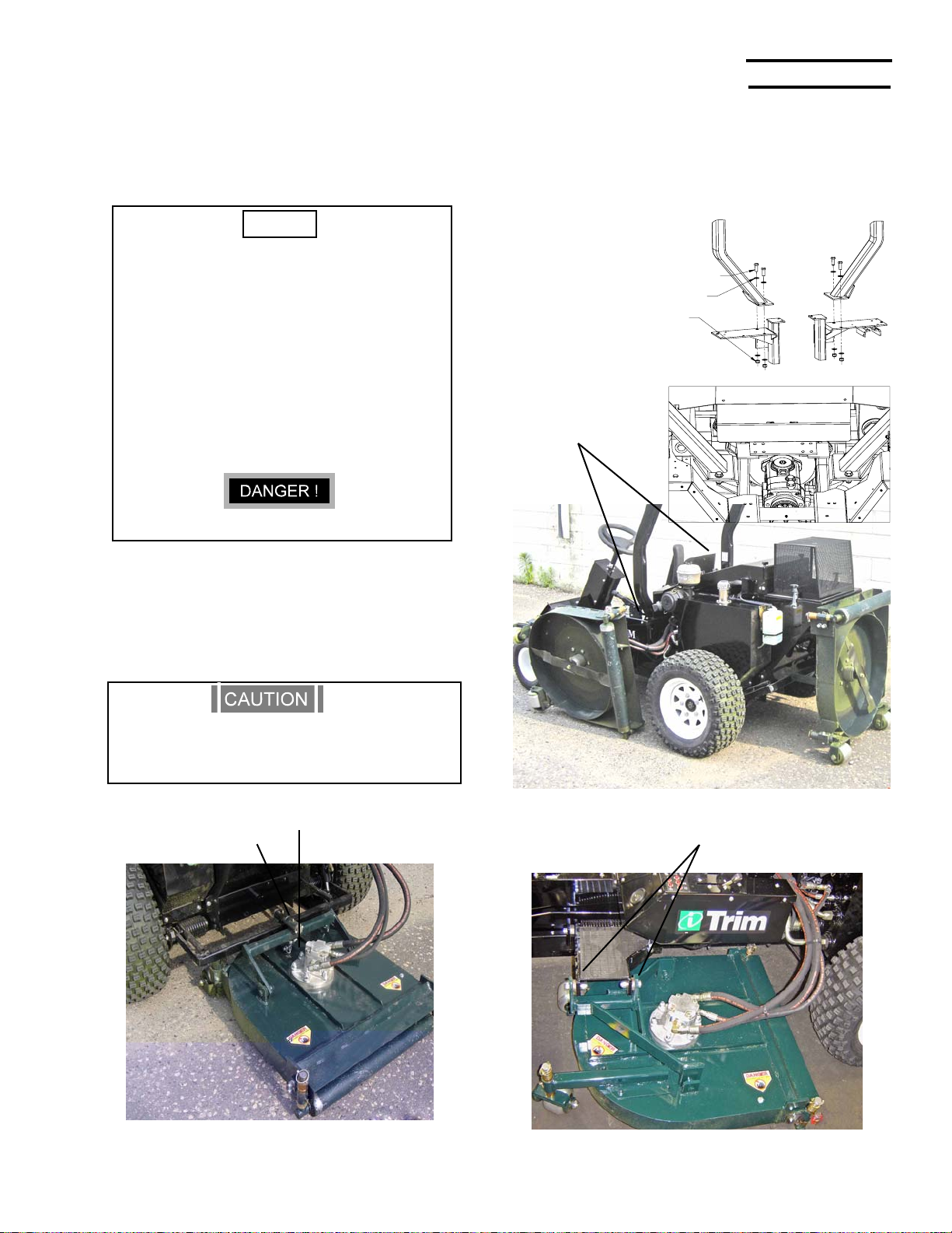
2.2—REAR DECK ASSEMBLY
1. Remove crating top, front and sides from deck crate.
Unscrew blades from crate.
2. Remove rear deck from crate and position behind
tractor as shown in Figure C. Remove roll pin and washer
from attachment shaft.
3. Insert a 1/2” rod into lift arm (Fig B) to lower and line-up the
lift arm with the deck bushing. Insert shaft and secure with
washer and roll pin. Remove wood spacer.
2.3—LEFT/RIGHT DECK ASSEMBLY
1. Remove left and right decks from crate and position near
tractor as shown in Figure D. Remove attachment bolts.
2. Hold down and line-up lift arms with decks. Attach with
supplied bolts and washers. Install lift chains.
Use jack stands under tractor whenever
elevated off the tires.
Do not engage deck motors untill tractor is
fully assembled with decks.
Wood Spacer
Insert rod
FIGURE B
12
FIGURE A
Page 13
I-TRIM
HEX BOLT ½-20 X 1½ GR 5
(4)
WASHER ½ SAE
(8)
NUT, NYLOCK ½-20
(4)
®
2.4—DECK MOTORS AND BLADES
The I-Trim is available with standard or mulching blades. The Rear/Right decks require a RH
blade and the left deck uses a LH blade.
NOTE
MULCHING BLADES
Rear/Right -P/N 306245 (stamped 306245)
Left -P/N 306311 (stamped 306311)
STRAIGHT BLADES
Rear/Right - P/N 306368 (stamped 4607)
Left - P/N 306367 (stamped 6406)
Motor rotation direction is stamped on the flange
of each deck motor. Rot ation is clockwise (from
above) on right and rear decks and counterclockwise on left deck.
NEVER START TRACTOR WITH DECKS ROTA TED
1. Rotate decks vertical as shown in Fig E. Install deck
motors with hoses rotated as shown in Fig C and D using
supplied botts and nyloc nuts. Note: install ring spacer
between motor and deck.
2.5—ROPS
1. Install roll-over protective structure with supplied bolts and
nuts as shown on Fig E. ROPS can be installed with seat in
forward position. Lower ROPS over seat and insert LH side
into position. Slide ROPS to RH side and spread it slightly
to clear brackets. Install with supplied fasteners.
.
ROPS attachment points
2. Install lift chains on rear deck with supplied bolts. Note:
The rear deck has a anti-flip chain with quick-release
connector link to allow easy removal for HOC adjustments.
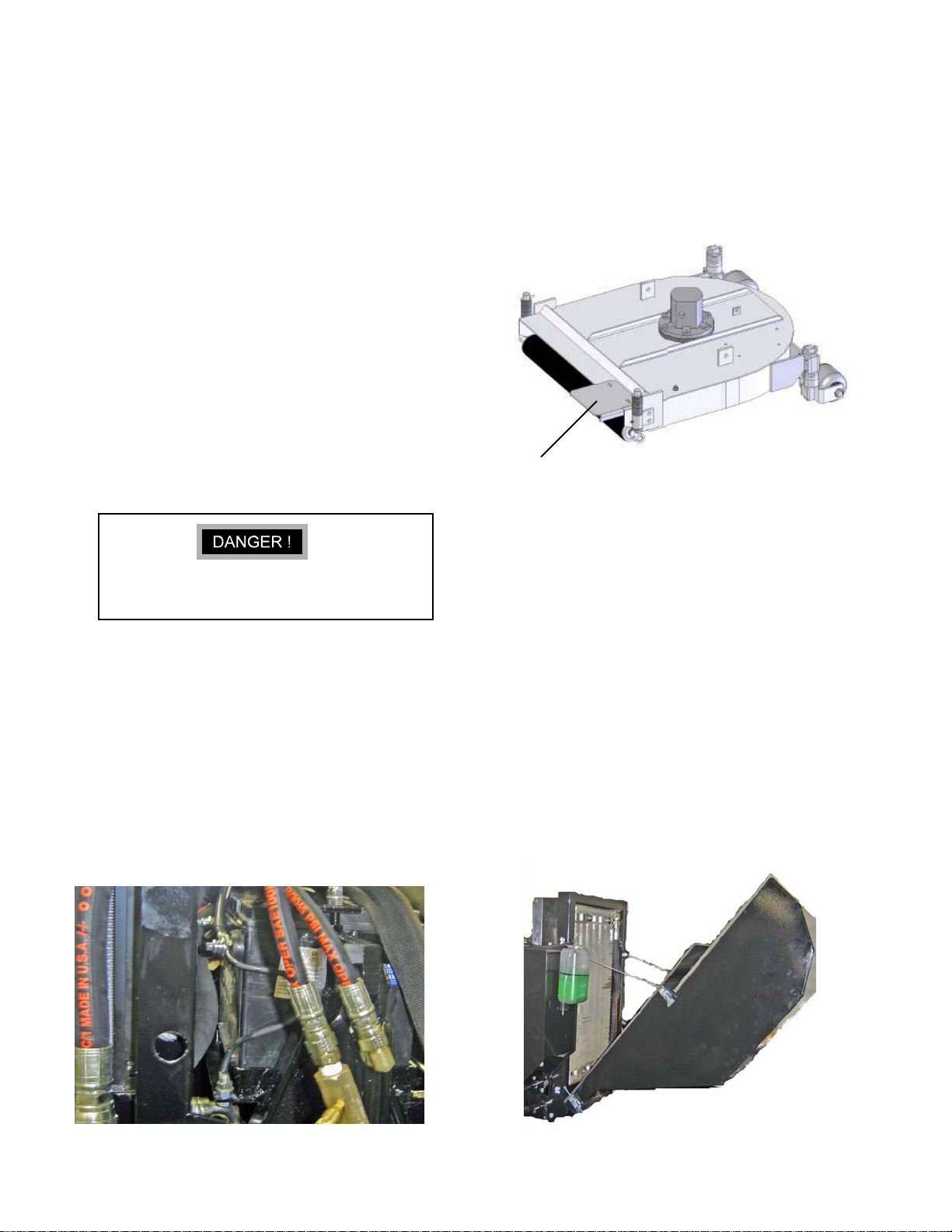
Make sure anti-flip chain is installed on rear deck
to prevent deck from rotating during operation.
Anti-flip chain
Attachment shaft and roll pin
FIGURE E
Side deck attachement bolts
FIGURE C
FIGURE D
13
Page 14
2.6—ENGINE CRANKCASE
Crankcase oil has been installed at the factory. However it
is recommended that the engine be checked for proper oil
level before starting. Refer to separate engine manual
included with each I-Trim Mower.
2.7—HYDRAULIC OIL
1. The hydraulic oil has been installed in the oil tank
(1, Fig. G) at the factory, however it is recommended that
the oil level be check before operation.
2. Check oil level by removing pipe cap. The oil level should
be at the bottom edge of the screen. If required, add a
small amount of oil to the tank. and replace cap.
Recommended oil is ISO 68 Hydraulic grade oil.
2.9—GUARD FOR DECK DISCHARGE
Each I-Trim Deck is supplied with a safety guard for the
rear discharge area. These guards are supplied to
prevent accidental insertion of a person’s foot and need to
be installed as shown in Fig. G.
2.8—BATTERY
Follow the battery manufacture’s instructions on
safety, maintenance and inst allation procedures.
The I-Trim is shipped with a Exide Model 60 Premium,
Type 78-60. Only replace with an equivalent battery.
1. Remove rear RH wheel to replace battery. Install
battery with side mount terminals facing toward
engine. See Fig F.
2. Place battery hold down strap over bolts and secure
with flat washers and hex nuts. Do not over-tighten.
3. Connect the red ignition wire to the positive (+)
terminal of the battery. Attach the engine ground wire
and frame ground wire to the negative (–) terminal of
the battery.
Guard
FIGURE G
2.10—SCREENBOX FOR RADIATOR
The I-Trim may be supplied with a pivoting rear screenbox
as shown in Fig. H. The screenbox needs to be installed
onto lower pivot brackets and secured with supplied
cables and snap-latches.
14
FIGURE F
FIGURE H
Page 15

3—GENERAL INFORMATION
NOTE
If adjustments are necessary see section 5.0 of
the is manual for instructions.
3.1—ENGINE
Your machine is powered by a 3-cylinder Briggs and Stratton
turbocharged diesel engine which uses diesel fuel. Engine
speed is controlled by means of a throttle lever mounted on
the dash panel.
A separate Engine Manual, prepared by the engine manufacturer is supplied. Study the manual carefully until you are
familiar the maintenance, operation, adjustment and repair of
your equipment. Proper attention to the engine manufacturers
directions will assure maximum service life of the engine and
highest operating efficiency.
I-TRIM
®
3.2—TRACTION DRIVE TRAIN
Power from the engine is transmitted by direct drive to the
variable displacement pump. The pump supplies hydraulic
fluid to the hydraulic motors.
3.3—MOWER DECK DRIVE
Hydraulic power to the deck motors is actuated by electric
switch mounted on the RH control panel. This switch actuates
a solenoid valve in the deck manifold.
3.4—INTERLOCK SWITCHES
There are three safety switches on your I-Trim. They are a
safety precaution, which will allow you to start your mower only
when the traction pedal is in neutral, the deck motor control
switch is in the disengaged position and the operator is seated
on the tractor. If you are able to start your mower with the
pedal or switch in any other position, adjustment of the
switches may be required. After engine is started, it will
continue to run if you leave the seat (as long as the deck
switch is off and the pedal is in neutral).
Never operate the machine if the interlocks are
not operating properly. Accidental startup could
cause severe injury . Refer to T roubleshooting section (Sec 9).
15
Page 16
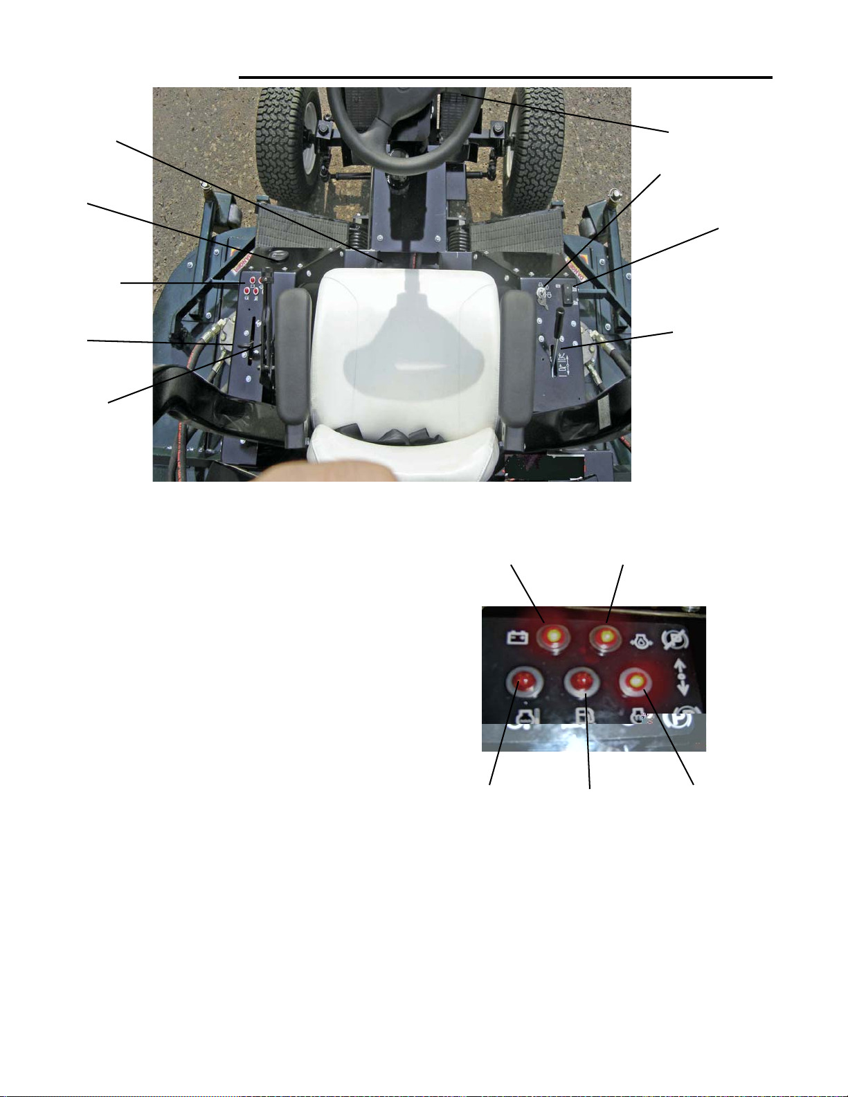
4—CONTROLS
10
2
3
4
8
FIGURE J
4.1—IGNITION SWITCH
Insert key in switch (1, Fig.J) and turn clockwise to on
position and wait until the glow plug light turns off. After light
turns off, turn key clockwise as far as it will go to start engine,
then release. The deck rotation control switch must be in the
off position, the traction control pedal in the neutral position
and a operator must be sitting on the seat before starting
engine.
5 6
1
9
7
Battery Charging Oil Pressure LOW
Do not hold key in “ON” position more than 15 second at a
time.
Key should be removed when tractor is not in use to prevent
unauthorized operation.
Refer to section “5.2” for complete starting information.
4.2—INDICATOR LAMPS
After engine is started, illumination of any indicator lamp will
indicate a problem (3, Fig J). Stop engine and correct
problem.
When Key is turned to “ON” the Battery Charging, Glow Plug
ON, and the Oil Pressure indicator lamps should illuminate.
After 5 seconds, the Glow Plug ON light should turn off (Fig
K).
16
Water Temperature Water in Fuel Glow Plug ON
FIGURE K
4.3—HOUR METER
The hour meter (2,Fig. J) indicates the number of hours the
tractor has been operated. It can be used to keep track of
maintenance intervals and the amount of time required to
perform various tasks. The hour meter operates whenever the
ignition key is in the “on” position.
Your I-Trim Mower maybe equipped with a digital hour meter.
This meter will display a signal after 5 hours and every 25
hours thereafter, recommending that you perform maintanncel
and lubricate the mower. (see sec.7). The display will
automaticly reset after 2 additional hours of run time.
Page 17

4.4—THROTTLE LEVER
I-TRIM
®
Push throttle lever (4, Fig. J) forward to increase engine
speed, pull back to decrease the engine speed.
Position throttle at full throttle or slightly less for optimum
power and deck speed during mowing.
4.5—TRACTION PEDAL
The traction pedal (5, Fig. J) operates the forward and the
reverse direction and speed of the tractor.
Moving forward: push the forward or toe of the pedal down
with the ball of your foot, to increase the forward speed.
Moving backward: push the heel of the pedal down with the
heel of your foot, to increase the reverse speed.
When the traction pedal is released the machine will slow
down and stop. The traction pedal must be in neutral position
before mower will start.
4.6—SPEED CONTROL
The speed control (6, Fig. J) is meant to ease operator
fatigue by holding the forward speed to a constant that
is best suited for the present mowing conditions. The
stop also prevents overloading of the pintle shaft.
Adjust the hex head bolt up or down and lock it with the
lock nut to limit the pedal travel. Make sure the pintle
shaft on the pump is not bottomed-out by watching the
linkage deflection when pedel is all the way down.
4.9—DECK DRIVE CONTROL
By toggling the deck drive control switch ON (9, Fig.
J), an electric solenoid valve is activated which
engages power to the deck motors.
Pushing the switch to the OFF position disengages the
valve. This contrtol must be in the OFF position before
mower will start.
4.10—SEAT POSITION LEVER
The position of the seat is adjusted forward or
backward by actuating the seat lever (10, Fig. J).
Releasing the lever will lock the seat at its present
position.
4.7—DECK LIFT
The Deck Lift valve (7, Fig. J), will lift both wing decks
and rear deck by pulling lever to rear. Pushing lever to
front will lower all deck to the ground. Always lower
decks for mowing and storage.
Do not stand on mowers when in lifted position.
4.8—PARKING BRAKE
A convenient parking brake (8, Fig. J) is located just to
the left side of the operators seat.
Pulling back and over center will engage the parking
brake and moving it forward, as shown, will release it.
See section 6.1 for adjustments.
IMPORTANT
Always make sure brake is released before moving forward and ensure that the brake is engaged
when leaving the mower. Never try to stop the
forward motion of the unit with the parking brake.
17
Page 18

5—OPERATION
5.1—CHECK LIST
1. Fill the fuel tank with good quality, clean, diesel with a
minimum of 40 octane. Fresh fuel prevents gum from
forming in the fuel system. Fill tank to 1 inch (25 mm)
below filler neck. Do not overfill.
2. Check oil in the engine crankcase. It should be filled to
the full mark on the dipstick. Refer to Section 1.6 in this
manual for recommend oil viscosity.
3. Check all lubrication points outlined in the “Section 7.14
Lubrication” section of this manual. Check linkage for
traction pedal to the pump for wear or damage.
4. Check tires for proper inflation. Refer to section 1.4 of
this manual.
5. Check oil level in hydraulic reservoir. Oil level should be
level with the bottom of the screen when looking into the
fill neck and when unit is sitting on a level surface.
6. Check decks for desired cutting height. To provide a
satisfactory cut, it is essential for all decks be accurately
adjusted to exactly the same height. See 6.9 in the
Adjustments Section.
OPERATING SUGGESTIONS
Under no circumstances should the engine be
started with the operator or bystander standing
next to tractor or cutting units.
1. When starting the engine, the operator must be seated
on the seat, deck control switch must be OFF and
traction pedal must be in neutral (the center position).
6. Operate at speeds which allow you to have complete
control of the tractor and allow you to stop the tractor or
maneuver safely in case of an emergency. It is
recommended that you adjust the Speed Control (6, Fig.
J), to maintain a constant pedal postion/speed and
reduce the operator fatigue.
7. To obtain maximum mower life, the operator must use
discretion when mowing near gravel areas (roadway,
parking areas, cart paths etc.) By operating too close to
overlapping gravel areas, stones maybe picked up by
the mower and ejected under the deck causing wear to
the blades and damage from flying objects.
5.2— STARTING THE ENGINE
1. Sit in operators seat.
2. Place deck control switch in the “OFF” position (9, Fig
J).
3. Place the traction pedal in “Neutral” position (5, Fig J).
4. Engage parking brake (8, Fig J).
5. Insert ignition key, turn clockwise to “run” position and
wait until the glow plug ON light turns off. Turn key
clockwise to “start” and release key when engine starts.
Do not hold key in “start” position for more than 15
seconds or damage to the starter may result. If engine
does not start within this time, release the key and wait
for a few minutes before trying again.
5.3—DRIVING THE TRACTOR
1. Position throttle at full throttle or slightly less for optimum
power and deck speed.
2. The operator should practice mowing in an open clear
area, to become thoroughly familiar with the operation of
the tractor.
3. Never operate the mowers when they are in the up
position because of the dangers of flying objects and
exposed blades.
4. Plan your cutting pattern to avoid any unnecessary stops
or sharp, frequent turns. Study the area to determine the
best mowing procedure. Consider the height of the grass
and the type of terrain (level, hilly, or rough). Each
condition will require certain adjustments or precautions.
5. Before leaving the mower, always lower deck mowers
so that when exiting the mower and stepping on the nonskid pads of the wing mowers, it will not put excessive
strain on the lift mechanism.
18
2. Release parking brake (8, Fig. J).
3. Moving forward: Push the toe of the traction pedal forward
with the ball of your foot, to increase the forward speed .
4. Moving backward: Push the heel of the traction pedal in
with the heel of your foot, to increase the reverse speed.
5. To return traction pedal to neutral, rock pedal with foot until
pedal stops. The pedal will stay in neutral when you
remove your foot.
T o avoid possible loss of control and/or serious bodily injury, avoid abrupt chages in
the tration pedal position. Reduce speed on
slopes, rough terrain, and in sharp turns to
prevent tipping or loss of control.
Page 19

I-TRIM
®
5.4—MOWING OPERATION
1. Check the turf area for debris that would cause
damage to the decks. Never operate the decks when they
are in the UP position because of the danagers of flying
objects and exposed blades.
2. When cutting large areas, the most satisfactory method is
to first cut the outer area and then mow clockwise toward
the center. The next time you cut, it is advised that you
mow in the opposite direction to prevent grass matting.
3. Cutting speeds are governed by conditions of turf, type of
terrain and opstacles to be encountered. Operate tractor at
slow speeds when turning.
5.5—MOWING
1. Stop tractor, by releasing the traction pedal, then slowly
lower the mower units (5, Fig.J) and (7, Fig. J).
Dropping mower decks abruptly could damage
them. Always check for bystanders before lowering.
1. When operating on hillsides or slopes, maintain full
engine speed, but let up on the traction pedal as power
requirements increase. This will maintain the
performance necessary.
2. It is best to mow along the side of the hill, starting at the
bottom and working upwards. This allows the machine to
negotiate the slope without mowing in a downhill
direction.
3. It is essential for the correct tire pressure to be
established for maximum traction and hillside holding.
5.7—PUSHING OR TOWING
INSTRUCTIONS
The I-Trim should not be pushed or towed with the engine not
running. If needed, the I-Trim can be pushed or towed at slow
speeds for very short distances without starting the engine.
Do not exceed 2 mph while pushing or towing.
A screw-adjustable valve is located on the underside of the
pump for towing. Note: Do not exceed 2 mph while pushing or
towing. Loosen the lock nut and turn the screw CCW to
release pressure. After towing, tighten the screw by turning
CW and lock into place with the locknut.
2. Engage deck control switch (9, Fig. J) to the ON position.
3. Depress traction pedal to the desired speed (sections
4.6 and 4.7). Deck speed is constant and ground speed is
variable with the traction pedal. Do not try to regulate
ground speed with engine throttle (section 4.5).
5.6—HILLSIDE OPERATION
The I-Trim has been designed for good traction and stability
under normal mowing conditions. However, caution must still be
used during slope operation, especially when the grass is wet.
Wet grass limits traction and steering control.
In order to minimize the possibility of tipping, the least dangerous method of operating on hills and terraces is to travel
horizontally to the hill. It is also advisable to avoid any unnecessary turns while operating on hills. Use extreme caution and
travel at reduce speeds.
19
Page 20

5.8—AFTER OPERATION
6—ADJUSTMENTS
1. Clean the entire mower after use. Remove loose grass
clippings and caked grass to prevent clogging the vented
areas, lubrication points, and corroding parts.
2. The engine is water cooled. Do not permit dirt or grass
clippings to accumulate on the air intake screen, engine
or radiator/oil cooler to prevent serious heat damage to
the engine,or hydraulic pump.
3. If fan blades become damaged, replace the fan.
5.9—CLEANING RADIATOR AND OIL
COOLER
1. If grass clippings become trapped in radiator and oil
cooler, use compressed air from fan side to blow them out.
The screenbox can tilted back for cleaning by loosening
quick-latches (Sec. 2.10 or Fig. H below ).
2. If grass clippings become trapped between radiator and
oil cooler, the oil cooler can be tilted back for cleaning
(Fig M). Be careful not to damage the fins on the
radiator and oil cooler during cleaning.
Read each instruction completely and, make sure you understand it before making any adjustments. Follow all the safety
precautions.
To avoid possible serious injury, before making
any adjustments or performing maintenance, engage parking brake, place all tractor controls in
neutral, lower decks to the ground, turn ignition
switch “off” and remove key.
6.1--TRACTION PEDAL ADJUSTMENTS
The traction pedal (1, Fig.M) is equipped with a safety switch
(2, Fig. M) and a neutral centering device. The switch prevents
the engine from starting when the pedal is positioned in
reverse or forward. The centering device locates neutral
positioning of the pump.
1. Prior to adjusting for creep, elevate the wheels off the
ground and support the vehicle with jack stands. Any
adjustments should be done while the hydraulic oil is
warm.
FIGURE L
2. To adjust the creep of the drive wheels, loosen the
fastener attaching the clevis to the control arm. Rotate the
clevis and re-atach to achieve neutral.
3. Once the traction pedal has been adjusted, the safety
switch (2, Fig. M) should not have to be re-adjusted.
Check neutral switch operation before use. If needed,
adjust the switch so that the engine cannot be started
unless the pedal is in the neutral position.
6.2—PARKING BRAKE ADJUSTMENT
The parking brake should be set so that it holds the tractor
securely. The parking brake must be released before the
traction pedal is engaged.
1. Adjust the brake by loosening set screw in the brake knob
and turning knob clockwise to tighten, or counterclockwise
to loosen, then retighten set screw.
2. After making any adjustment check brake on flat ground, so
that the tractor will not move with brake engaged.
3. Further testing by putting tractor on a hill, leaving the engine
on and engaging park brake. and then test with the engine
off.
20
FIGURE M
Page 21

I-TRIM
®
6.3—GROUND SPEED CONTROL
The I-Trim does not have an adjustable ground speed control.
See Section 4.7 for pedal adjustment.
6.4—REAR MOWER LIFT
The rear mower lift height has been preset at the factory and
normally will not need to be adjusted.
The I-Trim may be
fitted with a needle valve on the rear lift cylinder.
Turning the needle valve CW will slow the lift and
lowering speed of the rear deck. Always lock the
adjusment knob down when done adjusting.
6.5—HEIGHT OF CUT ADJUSTMENT
1. To set the height of cut, lift the deck to a vertical position (Fig.
O). Remove linch pins and assemble spacers (1 Fig. 0) to set
height of cut desired. Loosen side attachmement bolts of rear
roller if needed to slide rear roller out (2 Fig. O). Min HOC is 1.5”
with no spacers under the roller attachment shaft. Max HOC is
4”
REAR, RIGHT DECKS -SHARP EDGE UP
LEFT DECK- SHARP EDGE UP
2
1
FIGURE O
6.6—BLADE REPLACEMENT PROCEDURE
IMPORTANT
Rollers must be adjusted to the same height so
that there will be uniform cutting the entire width
of the mower.
To avoid possible serious bodily injury, before
performing and adjustments, maintenance, or lubrication, place all controls in “neutral”, lower
the mowers to the ground, engage parking brake,
turn ignition switch off and remove key.
Use heavy gloves and be careful. Blades are
very sharp.
Replace blades with factory blades only. Standard discharge
blades and mulching blades are available. Note: The Rear
and Right decks use the same blade (RH). The Left deck uses
a LH blade.
Be extremely careful not to let tools, your fingers
or clothing get caught in the blades. Use approved safety glasses to protect eyes from flying
particles and abrasives.
NEVER START ENGINE WITH DECKS ROTATED
UP AND NOT IN A HORIZONTAL POSITION.
1. Loosen 1/2-13 Grade 8 bolts and remove blades. Install
new blades as shown in Fig. O. Make sure cutting edge is
closest to ground and correct blade is on each deck.
2. Install bolts and torque to 98 ft-lbs. If needed, replace
2. Make sure adjustment nuts are tight before mowing.
21
Page 22

7—MAINTENANCE
To avoid possible serious bodily injury, before
performing and adjustments, maintenance, or lubrication, place all controls in “neutral”, lower the
mowers to the ground engage parking brake, turn
ignition switch off and remove key.
7.1—GENERAL MAINTENANCE
The long trouble free life of your machine depends on the
maintenance it receives. Set-up a maintenance program for
your I-Trim to cover the following points:
Keep tractor and decks clean
.
Keep all moving parts properly lubricated (sec. 7.14).
Keep all parts properly adjusted.
Inspect for loose, worn or damaged parts.
Keep shields in place at all times.
Keep tires properly inflated.
7.3—BATTERY
1. Make certain the ignition switch is in the “off” position and
the keys have been removed.
2. Refer to section 1.4 in this manual for battery
specifications.
Always wear protective glasses or goggles and
protective clothing when working with batteries.
Always connect the “ground” (black) cable last
and remove it first whenever performing any
maintenance.
Batteries contain sulfuric acid and generate explosive mixtures of hydrogen and oxygen gases.
Keep any device, which may cause sparks or
flames away from the battery to prevent explosions.
Read and follow the battery manufacture’s instructions on safety, maintenance and installation procedures.
If your inspection reveals worn or damaged parts replace
these parts before operating machine or before actual
breakdown occurs.
To avoid injury from hot, high-pressure oil, never
disconnect hydraulic hoses with attachments in
up position. Never rub hands across tubes, hoses
or fittings to check for leaks. Hydraulic fluid escaping under pressure can have sufficient force
to penetrate the skin.
7.2—ASSEMBLY AND DISASSEMBL Y
Use the illustrations in the parts catalog as reference for
disassembly and assembly of components. Always maintain
relative position of parts when disassembling. Clean and
lubricate individual parts and components as required.
3. When the battery is being installed or removed make
sure that the positive and negative terminals do not
come in contact with metal tractor parts at the same time
or severe damage may result.
4. Battery connections must be kept clean and tight at all
times. Loose cables will cause eventual battery failure.
Keep terminal covers in place.
5. Use soap and water to clean the battery as required.
Care must be taken to prevent soap and water from
getting inside battery.
6. Clean the terminal contact surfaces with a battery
terminal brush or steel wool.
7. Tighten cables securely to battery terminals.
8. Apply a light coat of petroleum jelly or chassis lubricant
to terminals and cable ends after assembly to prevent
corrosion.
22
Page 23

I-TRIM
®
7.4—CHARGING A BA TTER Y
To avoid possible injury, stand away from
battery when charger is turned on. A damaged
battery or a battery with an internal short could
explode
Charge battery ONLY in a well verted location, away from
sparks or open flame.
1. Remove the battery from the tractor before charging.
2. Be sure charger is “off “.
3. Connect charger leads to battery. Connect the positive
(+) connector from the charger to the positive battery
terminal. Connect the negative. (–) connector of the
charger to the negative battery terminal.
4. Charge the battery using one of the methods shown below.
Follow the manufacturer’s instructions on the charger.
5. If when charging the battery, if violent gassing or spewing
of electrolyte occurs, or the battery case feel hot
(125*F - 52C), reduce or temporarily halt charging to avoid
damaging battery.
6. Always turn charger to “off” before removing a charger
lead from the battery.
7.5—BELTS
There are no belts on the I-Trim.
7.6—ENGINE FUEL FILTER
Before servicing the fuel filter, thoroughly clean outside of filter
housing and fuel hoses, dirt must not be allowed to enter into
fuel or fuel system. Refer to manufacturer’s Engine Manual for
instructions.
7.7—ENGINE
Refer to manufacturer’s Engine Manual for maintenance
schedule recommendations. Change oil and oil filter after the
first 50 hours of operation.
7.8—ELECTRICAL SYSTEM
Make certain all terminals and connections are kept clean and
properly secured.
1. Check switches regularly to be sure they are kept clean
and operating correctly
2. Keep wire harness and all individual wires away from
moving parts, hot parts, or sharp edges. this will prevent
abrasive wear or potential short circuits.
3. Exercise extreme care when working with electrical
system.
7.9—HYDRAULIC HOSES
To avoid serious bodily injury , always lower mowers to the ground, place all controls in neutral
and shut off engine before inspecting hydraulic
lines or hoses. Never run hands across tubes,
hoses or fittings to check for leaks.
Hydraulic hose and tube lines should be inspected every week
to check for cuts, loose connections, kinks and wear.
Be sure tubes and hoses do not come in contact withother
frame parts which could cause abrasive wear. Always replace
worn hoses or tubes before operating machine.
1. Assemble nut, sleeves and tube to fitting body with
minimum torque (finger tight) until flare contacts
seat on fitting body.
2. For tightening reference, mark a line lengthwise on both
the nut and adapter fitting with a marker.
3. Using a wrench, rotate the nut to tighten. Turn the nut the
amount shown in the chart below. The line will show which
fitting have been tightened and how much.
4. On hoses with “o-ring” fittings, make sure o-rings are
clean and hose fittings are properly seated by hand before
wrench tightening.
5. Hold the fixed portion of the hose coupling with one
wrench; use a second wrench to tighten or loosen the hose
nut. This will prevent damage to the fitting seal. When
tightening a hose, do not allow it to twist; hold it in a
normal, straight position.
Tube O.D. or hose, Rotate Number. of flats
3/8” 2
1/2” 2
5/8” 1-1/2 to 2
1” 3/4 to 1
23
Page 24

7.10—HYDRAULIC OIL
7.12—JUMPER CABLES
1. The oil level should be checked if any oil leaks are
dicovered. Oil level should be brought to decal mark on
the side of the oil tank.
2. Park the tractor on a level surface.
3. Oil should be at 60° F to 90° F (16 – 32 °C), when
checking level. Do not check level when oil is hot.
4. Drain and replace the hydraulic oil every 200 hours.
Use ISO 68 Hydraulic grade oil. Replace both hydraulic
filters every 200 hours.
The oil should be changed after a major component failure,
or if you notice any of the following.
• Present of water - (noted by a cloudy or milky
appearance)
• Present of air - (noted by foaming)
• Excessive heat - (noted by rancid odor)
5. To drain hydraulic oil tank, remove the drain plug in the
back of the hydraulic tank.
6. Reinstall drain plug and fill hydraulic tank until the oil is
evel with the bottom of the screen in the fill tube. Use only
filtered hydraulic oil. The total hydraulic system oil capacity
is approx. 10-12 gallons.
7. Jack up rear tires so they spin freely.
8. Start engine; operate the traction pedal and turn steering
from right to left to free the system of air. Recheck oil level.
The battery on the I-Trim is located at the rear of the tractor,
See.
1. Stop the engine on the vehicle with the good battery.
2. Connect one jumper cable to the positive terminal on the
good battery. Connect the other end of the jumper cable to
either the positive terminal on the dead battery or the
battery side of the solenoid located on the right front of the
engine.
3. Connect one jumper cable to negative terminal on dead
battery. Connect the other end to ground (frame) of vehicle
with the good battery.
7.13—DECK BLADE REPLACEMENT
When the deck blades become damaged or too worn to keep
sharp, they must be replaced. Follow the procedure below.
1. See Section 6.13 for instructions to replace deck blades.
7.11—HYDRAULIC OIL FILTERS
To prevent damage to the hydraulic system, the hydraulic oil
filters (located under right fender and under steering column
shroud) should be changed after the first 25 hours of operation
and every 200 hours thereater.
1. Remove the old filter
2. Install new filter, filling filter with oil before re-installing.
Apply oil to the O-ring of the filter prior to installation. Hand
tighten only.
3. Run engine at idle speed with hydrostatic pump in neutral
for five minutes.
4. Check hydraulic oil level and add oil if necessary.
Frequent checks of oil level in the hydraulic tank.
Should the pump run short of oil, immediate and perma
nent damage will result
24
Page 25

THIS PAGE IS BLANK
I-TRIM
®
25
Page 26

7.14—LUBRICATION
Figure U shows the top view of the I-Trim
with guards removed. Lubricate your
tractor at the recommended locations and
intervals using proper lubricants so that
maximum service and long life of the
machine may be obtained.
Your I-Trim Mower maybe equiped with a
digital hour meter. This meter will display a
signal after 5 hours and every 25 hours
thereafter, recommending that you change
engine oil and lubricate the mower.
Before doing any work on
your machine, stop the
engine, remove the ignition
key and set parking brake.
SYMBOLS
GREASE - Lithium base
or equivalent
OIL - Light machine oil
FIGURE U
Fre- No.
Item quency Location Type of of
(Hrs.) Lubrication Places
1 Daily Dipstick / left side of Engine Check level 1
2 Daily Radiator Reservoir Bottle Check level 1
3 Daily Hydraulic Tank Check level 1
4 Daily Fuel Tank Check level 1
5 Daily* Pre-Air Filter Inspect/Clean 1
6 Daily* Screenbox, Radiator Fins/ Rear Inspect/Clean 1
7 Weekly Height Adjustment Shaft Housings Grease, Lithium 12
8 Weekly Tires Check Pressure 4
9 Weekly Hardened Bushines/Deck Lift Arms Light Machine Oil 10
9100/600** Air Filter Element / Left side of Engine Inspect, Replace as Nec. 1
10 100 Fan Belt / Rear of Engine Inspect, Adjust 1
11 150** Drain Plug / Underneath Engine Change Oil 1
12 Monthly Front Axel - Rod Ends, King Pin.pivot Grease, Lithium 6
13 Monthly Radiator / Rear of Engine Check coolant level cold 1
14 Monthly Rear Lift Pivot / Above Rear Deck Grease, Lithium 2
15 Monthly Lift Shaft Bushings / Under Seat Grease, Lithium 1
16 200 Battery / Right Side of Engine Check Electrolyte 1
17 300** Canistor / Left Side of Engine Change Oil Filter 1
18 600 Rocker Arms / Top of Engine Check Valve Clearance 1
19 800 Fuel Filter / Left side of Engine Replace 1
20 Yearly Pedal Shaft Bushings / Behind Bumper Grease, Lithium 2
21 200*** Hydraulic filters (2)/RH shroud,steering Replace 2
22 200* Hydraulic Tank / To Left side of Engine Drain, Flush, Refill 1
23 Yearly Radiator, Engine Block Change Coolant 1
* More often as necessary
** Perform first maintenance operation after 50 hours. All subsequent maintenance
performed at this interval. Service more often when operating under heavy load or in high
termperature.
*** Perform first change of hydraulic filters at 25 hours. All subsequent replacements at
200 hours
26
Page 27

I-TRIM
®
27
Page 28

8—STORAGE
8.5—TIRES
8.1—GENERAL INSTRUCTIONS
When you do not plan to use your vehicle for some time, it
should be stored in a dry and protected place. Unnecessary
exposure to the elements may deteriorate its appearance and
shorten the usual service life.
8.2—ENGINE
1. Drain the fuel from the fuel tank.
2. While the engine is still warm, change oil. Refer to
Engine Manual for manufacture’s instructions.
3 Remove glow plugs and pour about 3cc of engine oil
into each cylinder. Replace glow plugs and crank slowly
to distributre oil.
4. Clean exterior of engine. Paint the exposed metal or
coat it with a light coating of rust preventative oil.
8.3—BATTERY
1. Before storing the vehicle, clean the tires thoroughly.
2. Jack up the vehicle so that the load is off the tires. If it is
not jacked up, check the tires at regular intervals and reinflate as necessary to keep them at the recommended
maximum pressure. (Indicated on tires side wall)
3. Store the vehicle so that the tires are protected from
sunlight.
8.6—STARTING THE ENGINE AFTER
STORAGE
If mower is cold, move the mower to a heated location and
allow it to come to room temperature( 70° F - 22 °C) before
starting. This will prevent premature wear of hydraulic system
components.
Follow the towing procedure (in Sec. 5.8).
1. Check and recharge the battery according to recommen-
dations given in Section 7.4 page 22.
2. Reinstall the battery
1. Remove battery and clean it. Refer to manufacturer’s
manual for specific instructions.
2. Maintenance free batteries should be stored in an
upright position in a cool dry place. Storage above 80° F
greatly increases self-discharge. If wet batteries are
discharged, the electrolyte will freeze when stored below
20° f (-7 °C)
IMPORTANT
The battery should be checked every 60 to 90
days while in storage, and should be recharged
if necessary.
8.4—TRACTOR
Wash, clean and completely lubricate the tractor. Paint any
exposed metal.
3. Check oil level in crankcase and hydraulic oil tank.
4. Fill the fuel tank with fresh diesel fuel. Prime fuel filter by
pushing down and releasing until firm.
5. Before driving the vehicle, check to make certain that the
tires are properly inflated to the proper pressure.
6. Either move the vehicle outdoors or keep doors and or
windows wide open to provide sufficient ventilation before
starting engine this will prevent danger from carbon
monoxide gas in the exhaust.
7. Start the engine but do not operate at high speed
immediately after starting. Allow time for it to become
properly warmed and lubricated.
28
Page 29

9—TROUBLE SHOOTING
T o avoid possible serious injury , before making any adjustments or performing maintenance, place all controls in neutral, fully lower
cutting units to the ground, turn ignition
switch to “OFF”, remove key and set parking
brake.
ENGINE WILL NOT START
I-TRIM
1. MAKE WORK AREA SAFE:
Make sure personnel in the area are out of
harms way if the engine starts or the decks
run unexpectedly. Engage the vehicle
parking brake.
2. READ MANUAL:
Become familiar with wiring diagram and
the locations of the various electrical
components.
®
The operator must be seated.
Check position of controll switch (on dash).
Switch must be in the OFF position.
Check to see that the traction pedal is in neutral.
(neutral is in the center position).
Check all safety switches for conductivity. See
Electrical System diagram, Fig. 11, Page 48.
Replace switches if necessary.
Check fuel in tank
Check battery. Check charge level, charge or replace as
needed. Clean battery terminals if necessary.
Check electrical wiring and safety switch operation.
TRACTOR WILL NOT MOVE
Check that parking brake is not engaged.
Check the linkage from the traction pedal to the pump control
mechanism to ensure complete attachment of all linkages.
3. DISCONNECT HOUR METER BEFORE
REMOVING SIDE COVER:
It may be necessary to remove both side
covers, rear cover and hood to give access
to battery, ignition switch, circuit breaker,
blade run switch, circuit board and other
electrical components. It may also be
necessary to remove the front bumper
cover to gain access to the neutral pedal
switches.
4. CHECK BATTERY:
Make sure battery is in good condition and
fully charged.
5. CHECK BATTERY CABLES:
Check battery cables for tightness at both
battery and engine.
6. CHECK GROUND STRAP:
Check ground strap for tightness and
condition.
DECKS WILL NOT TURN
Check for debris jammed between the blade and
deck platform.
9.1—ADVANCED TROUBLE SHOOTING PROCEDURES
VEHICLE PREPARATION FOR DIAGNOSIS AND
COMPONENT IDENTIFICATION
7. DECK RUN SWITCH OFF:
Put deck run switch in the off position.
8. RESET CIRCUIT BREAKER:
The circuit breaker has a reset button.
Reset circ uit breaker after checking for a
short or grounded wire downstream of the
circuit breaker.
29
Page 30

9. SAFETY INTERLOCK BOARD (SIB):
The ITrim is equipped with an integrated
circuit board designated as the Safety
Interlock Board (SIB). The SIB controls the
vehicle starter cranking, engine run and
deck run circuits and the indicator lights.
The starter motor won’t crank unless the
following conditions are met:
a. Operator must be sitting in the
seat.
b. Foot Pedal must be in neutral
position.
c. Deck Switch must be off.
If the operator gets up off the seat the
engine will continue to run if the following
conditions are met:
a. The foot pedal is in neutral
position.
The deck switch is off.
If engine doesn’t crank:
1. With a test light, check for power at plastic
connector on the starter solenoid while an
assistant turns the key.
If test light doesn’t come on:
The problem is in the wiring or
terminals between the start relay
and the starter solenoid.
If test light comes on:
The problem is in the starter
solenoid or starter.
If engine cranks:
1. Remove jumper and reinstall terminals on start
relay.
2. Turn the ignition switch to the on position.
3. Check the indicator lights on the SIB with an
assistant sitting on the seat of the vehicle.
a. All four indicator lights should be on.
PROBLEM: STARTER WON’T CRANK - with
pedal in neutral position, operator in seat and
deck run switch in off position.
1. Using a test light, check for power to the start
relay, terminal 87 when the ignition switch is
turned to the start position.
If test light doesn’t come on at start relay, terminal
87:
1. With a test light, work back from the start
relay, checking for power at the ignition
switch, circuit breaker and positive battery
post on the starter solenoid.
2. Replace defective components or repair
wiring.
If test light comes on at start relay, terminal 87:
1. Remove contact terminals, terminals 87 and
30, from start relay.
2. Connect the contact terminals together with
a temporary jumper made with spade
terminals and 10 GA wire.
3. Turn the ignition switch to the start
position.
If no lights come on:
1. Check for a blown fuse on the SIB and
replace if faulty.
2. Check for power to the SIB by checking
fuse receptacle with a test light. The left
slot of the fuse receptacle should have
power.
If there is no power to the left slot of the fuse
receptacle:
1. Check for power at terminal J2-2 on the SIB
with a test light. (Insert test light probe into
backside of connector.)
If there is power at terminal J2-2 on the SIB but
not at the left slot of the fuse receptacle, the
SIB is faulty and should be replaced.
If there isn’t power at terminal J2-2 on the SIB,
the problem is in the wiring or the terminals
between the ignition switch and the SIB.
30
Page 31

If no lights come on and fuse is good
and there is power to the board:
1. Make sure SIB is grounded by checking the
resistance between the capacitor ground on the
SIB and the vehicle frame. Resistance should
be 0.
If SIB is not grounded:
1. Check the resistance between terminal J1-7 on
the SIB and the vehicle frame. Resistance
should be 0.
If number 1 above is not 0 and number 2 above is 0:
The SIB is faulty and should be replaced.
If number 1 above is 0 and number 2 above is not 0:
The problem is in the wiring or terminals between
J1-7 and the frame ground which is located on
the ROPs support behind the SIB bracket.
If SIB is grounded and lights still don’t come on:
1. Temporarily put jumper between terminals
J3-1 and J3-2 on SIB. (The jumper can be
a thin piece of U-shaped wire inserted into
the backside of the connector.)
a. The seat relay indicator light, (the first light
on the left side of the SIB,) should come
on.
If the seat relay indicator light doesn’t come on:
The board is faulty and should be replaced.
If the seat relay indicator light comes on:
(With the jumper but not with a person in the
seat) The problem is in the seat or the
wiring between the SIB and seat.
If the seat relay indicator light comes on but
none of the others do with the SIB
grounded:
The SIB is faulty and should be replaced.
If the seat relay indicator light on the SIB and
the run relay indicator light on the SIB are on
but the pedal relay indicator light and/or the
blade relay indicator light are not on,
troubleshoot the pedal and blade relay circuits
individually as follows:
I-TRIM
®
If the pedal relay indicator light is off with seat
and run relay indicator lights on:
Temporarily put jumper between terminals J3-3
and J3-4 on the SIB. (The jumper can be a
thin piece of U-shaped wire inserted into the
backside of the connector.)
The pedal relay indicator light, (the second light
from the left side of the SIB,) should come on.
If the pedal relay indicator light doesn’t come
on with the jumper:
The board is faulty and should be replaced.
If the pedal relay indicator light comes on with
the jumper:
The problem is in the pedal switches at the
front of the vehicle or in the wiring from the SIB
to the pedal switches. (The arms that the
pedal switches are mounted on, must fully
contact the foot plate of the vehicle to actuate
the switches. Both switches must be actuated
to complete the circuit to the SIB.)
If the blade relay indicator light is off with seat
and run relay indicator lights on.
Temporarily put jumper between terminals J2-2
and J2-3 on SIB. (The jumper can be a thin
piece of U-shaped wire inserted into the
backside of the connector.)
The blade relay indicator light, (the third light
from the left side of the SIB,) should come on.
If the blade relay indicator light doesn’t come
on with the jumper:
The board is faulty and should be replaced.
If the blade relay indicator light comes on with
the jumper:
The problem is in the deck run switch the
wiring or terminals to the deck run switch
terminal 5 or the wiring or terminals from the
blade switch to the SIB.
The starter should crank with all the above
operating correctly.
31
Page 32

Problem: STARTER CRANKS BUT ENGINE
WON’T START
Check the electrical system after checking for fuel
in the tank and after priming the fuel system.
Using a test light with the ignition switch in the on
position, check for power at the fuel pump
connector on the engine.
If light comes on:
Test the resistance of the deck run
hydraulic valve coil (at coil connector).
The resistance should be approximately
4c ohms. Current flow through the coil
therefore should be approximately 3
amps. at 14 volts.
If test light comes on:
Make sure fuel pump is properly
grounded by using the fuel pump for the
test light ground.
If the fuel pump is properly grounded
the problem is in the fuel pump.
If test light doesn’t come on:
Using a test light check for power at
terminal J4-2 on the SIB.
If test light comes on at terminal J4-2
on the SIB:
The problem is in the wiring or
terminals between the SIB and the
fuel solenoid.
If test light doesn’t come on at terminal
J4-2 on the SIB:
The board is faulty and should be replaced.
Problem: DECK MOTORS WON’T RUN WITH
ENGINE RUNNING
1. Temporarily disconnect connector at blade
run hydraulic valve.
2. Start engine, put deck run switch to on
position.
3. Check terminals of wiring connector with
test light.
If the coil resistance is correct the
problem is not in the electrical system.
If light doesn’t come on:
1. Check for power at
terminal J2-6 on the SIB.
2. Check for power at
terminal 2 on the Deck
Run Switch.
3. Check for power at
terminal 1 on the Deck
Run Switch.
If the light doesn’t come on for number 1
above:
The board is faulty and should be
replaced.
If the light comes on for number 1 above
but not 2:
The problem is in the wiring or
terminals between the SIB and the
deck run switch.
If the light comes on for numbers 1 and 2
above but not 3:
The deck run switch is faulty and
should be replaced.
If the light comes on for numbers 1,2 and 3
above:
The problem is in the wiring or
terminals between the deck run switch and the
blade run valve.
32
Page 33

I-TRIM
®
FRAME
GROUND
BLK
-
BATTERY
+
D
R
E
ENGINE
GROUND
BLK
RUN
BLADE
RED
5
RED
4
STARTER
3
RED
ALTERNATOR
L
IG
47
48
RED
WHT
BLK
RED
VALVE
FUEL
PUMP
4
2
OIL
44
YEL
PRESSURE
ENGINE
TEMPERATURE
46
BLU
WHT
PLUGS
GLOW
FUEL
FILTER
51
7
BLK
RED
BLU
WIRING DIAGRAM
LTBLU
23
LTBLU
25
ITRIM
5
7
5
2
5
6
5
FRAME
GROUND
LTBLU
RED
24
RED
4
LTBLU
START
RELAY
30
86
85
87
0
3
6
26
B
A
5
2
1
4
SWITCH
DECK RUN
WHT
2
RED
RED
WHT53
3
LTBLU
22
JUMPER
D
R
E
IGNITION
RED
5
6
RESET
BUTTON
CIRCUIT
RED
BREAKER
OIL
PRESS
1
L
S
B
SWITCH
BATT
RED
BLK
SEAT
PANEL
LIGHT (5)
INDICATOR
INSTRUMENT
PLUG
GLOW
1
6
-
+
-
FILT
FUEL
+
-
14
+
-
TEMP
+
WATER
O
HOUR
METER
PEDAL
SWITCHES
0
1
7
WHT
19
18
K
L
B
5
0
BLK
5
0
D
R
E
K
L
B
5
1
C
K
L
B
B
A
1
2
15
-
K
L
B
O
+
O
BLU
10
WHT
K
L
B
K
L
B
W
H
T
K
L
B
BLK
RED
K
L
B
D
R
E
123
17
BLK
4
J3
3
2
1
J3
9 10
9
8 10
5 7
6
3
4
J1
1
2
JI
1 2 3 4 5 6 7 8
11
BOARD
SAFETY INTERLOCK
LTBLU
LTBLU
LTBLU
LTBLU
LTBLU
4
5
6
321
J2
3
1
4
4
2
J2
RELAY
LIGHT (4)
INDICATOR
YEL
RED
WHT
BLU
WHT
6
5
478
123
J4
5
6
5
3
1
7
6
4
2
8
WHT
WHT
D
B
A
C
J4
55
R
E
Z
Z
B
U
L
A
Y
E
R
N
U
R
L
A
Y
E
R
B
L
A
D
E
R
L
A
Y
E
D
A
E
L
P
L
A
Y
E
R
S
A
T
E
R
L
A
Y
E
GROUND
CAPACITOR
TIMER
GLOW PLUG
WHT JUMPER
RED
RED
6
RELAY
GLOW PLUG
30
WHT JUMPER
86
85
87
7
50
RED
FIGURE 11
33
Page 34

34
Page 35

I-TRIM
®
35
Page 36

FIGURE 1
36
Page 37

I-TRIM
®
FIGURE 1—SCREEN BOX, GUARDS, ROPS, MISC
1 1 306435 WELDMENT - SIDE COVER, LH
2 1 07063 HOUR METER
3 5 07697 LED
4 1 306341 PANEL - INSTRUMENT, LH
5 1 203086 THROTTLE CONTROL
6 1 306162 WELDMENT - BUMPER PLATE
7 1 306298 COVER - STEERING TOWER
8 1 305984 STEERING COLUMN
9 1 07071 STEERING WHEEL
10 1 07731 ROPS, FULL VISION
11 1 07065 KEY SWITCH
12 1 07496 SWITCH - DECK MOTOR
13 4 07399 KNOB, DAVIES MOULDING CO #3035
14 1 306227 HOOD
15 1 07695 STARTER SOLENOID RELAY, WAYTEK #75002
ITEM NO. QTY. PART NO. DESCRIPTION
306526
16 1 07700 CIRCUIT BREAKER, WAYTEK #46374
17 4 07840 LATCH
18 1 306438 WELDMENT - SIDE COVER, RH
19 1 306351 ASSY - INSTRUMENT PANEL, RH
20 1 306350 WELDMENT - REAR COVER
21 1 306489 WELDMENT - SCREENBOX
22 1 306488 ASSY - SCREEN
23 2 306498 ASSY - SCREENBOX CABLE
24 1 306427 WEATHERSTRIP ASSY
37
Page 38

38
FIGURE 2
Page 39

I-TRIM
®
FIGURE 2—DECK LIFT ARMS AND PULL ARMS
1 2 07719 BUSHING - 1X1.5X2, BOSTON #B1624-16
2 5 02511 THRUST WASHER
3 1 02263 HEX NUT 3/8-24 NYLOCK
4 3 02403 FLAT WASHER - 3/8 SAE
5 1 07709 LIFT CYL - WING DECK
6 10 204447 BUSHING - PULL ARM
7 1 02036 HEX BOLT, 0.375 -24 UNF x 2¼ ZINC PL
8 1 306062 WELDMENT - LOWER PULL ARM, L
9 2 306188 WELDMENT - WING LIFT ARM
10 1 306191 WELDMENT - WING LIFT X-SHAFT
11 1 306061 WELDMENT - UPPER PULL ARM L
12 1 306242 NON SKID - WING PULL ARM
13 5 306177 BUSHING - PULL ARM INNER
14 1 04079 EXTERNAL RETAINING RING, 1.00 ID, H/D, McM #98585A121
15 1 306359 NON SKID - WING PULL ARM
ITEM NO. QTY. PART NO. DESCRIPTION
16 1 306232 WELDMENT - UPPER PULL ARM R
17 1 306234 WELDMENT - LOWER PULL ARM R
18 4 04048 ROLL PIN, .25 X 1.5
19 2 07714 LIFT SPRING - REAR PULL ARM
20 2 306320 END CAP - SPRING MOUNT, OUTER
21 1 07710 LIFT CYL - REAR DECK
22 1 306128 WELDMENT - LIFT ARM, RR PULL FRAME
23 2 02061 HEX BOLT, ½ -13 UNC x 1¼
24 1 306129 BUSHING - LONG, RR PULL FRAME
25 2 02333 EXTERNAL TOOTH LOCK WASHER, 1/2 ADAMS #348800
26 1 02751 HEX JAM NUT, NYLOCK, 3/4-16
27 1 306123 WELDMENT - PIVOT FRAME, RR PULL ARM
28 1 306241 PIVOT PIN - REAR DECK
29 1 306120 WELDMENT - LIFT FRAME, RR PULL ARM
30 2 306167 MOUNT - SPRING, RR DECK
31 2 306185 END CAP - SPRING MOUNT
32 2 02166 HEX BOLT, ½ -13 UNC x 5½
39
Page 40

40
FIGURE 3
Page 41

I-TRIM
®
FIGURE 3— SEAT, WHEELS, ENGINE, RADIATOR, HYD TANK
1 1 306195 WELDMENT - HYDRAULIC RESERVOIR
2 1 305497 STRAINER
3 1 07316 STRAINER
4 1 07783 CAP & FILL TUBE - HYDRAULIC TANK
5 1 B&S 820263 FILTER - AIR CLEANER, CARTRIDGE
6 1 306421 HOT AIR DEFLECTOR
7 4 306407 SPACER - HOT AIR DEFLECTOR
8 1 07706 SEAT
9 1 07185 BATTERY - ITRIM, EXIDE 78-60
10 1 02167 HEX BOLT, .312-18 X 7, McM #91247A609
11 1 306238 STRAP - BATTERY HOLDDOWN
12 2 07018 FRONT WHEEL & TIRE
13 1 07733 PRE-CLEANER
14 1 07708 MUFFLER
15 1 B&S 825117 CLEANER AIR
16 1 07771 AIR INLET HOSE
17 2 07681 REAR WHEEL & TIRE, TURF TAMER 23X10.5X12
18 1 306369 STRUT - REAR COVER
19 1 306361 WELDMENT - SUPPORT, REAR COVER
20 1 306226 RADIATOR SUPPORT - RH
21 1 306210 WELDMENT - RAD FRAME
ITEM NO. QTY. PART NO. DESCRIPTION
22 1 07683 OIL COOLER
23 4 07684 OIL COOLER MOUNT
24 1 07677 BRIGGS ENGINE AND ASSO. PARTS 3\LC 954 DTH
25 1 306225 RADIATOR SUPPORT - LH
26 1 306509 WEATHERSTRIP RAD SUPPORT
27 1 306508 WEATHERSTRIP RADIATOR
28 2 306502 PLATE
41
Page 42

FIGURE 4
42
Page 43

I-TRIM
®
FIGURE 4—WHEEL MOTORS, FILTERS, HYD COMPONENTS
1 1 07688 STEERING FILTER
2 1 07690 STEERING VALVE
3 1 07689 FILTER ELEMENT
4 1 306357 BRKT - LIFT VALVE, LH
5 1 07692 LIFT VALVE,
6 1 306356 BRKT - LIFT VALVE
7 1 305034 FILTER CANISTER, HYDRAULIC
8 1 305037 BASE - HYDRAULIC FILTER
9 1 306262 BRACKET - HYD FILTER
10 1 306358 TIE PLATE
11 1 07691 DECK LIFT VALVE
12 1 07726 BRAKE CALIPER - RH
13 1 306221 WELDMENT - FIREWALL
14 1 07687 CHECK VALVE, HYDRAULIC
15 4 07682 ISOLATION MOUNT
16 4 306150 PLATE - ENGINE MOUNT
17 2 07693 WHEEL MOTOR - END PORT, CHAR LYNN
18 2 07727 HUB - REAR WHEEL
19 10 07269 LUG BOLT
20 1 07725 BRAKE CALIPER - LH
21 1 BS 820373 MODULE - PREHEAT
22 1 07695 GLOW PLUG RELAY, WAYTEK #75002
23 1 07716 CIRCUIT BOARD
ITEM NO. QTY. PART NO. DESCRIPTION
24 4 07728 SPACER - CIRCUIT BOARD, McM#94639A454
25 1 306360 BRKT - CIRCUIT BOARD
26 1 306439 SPLASH GUARD - CIRCUIT BOARD
27 1 07798 BRAKE CABLE - LH
28 1 07348 BRAKE CABLE - RH
29 1 07346 PARKING BRAKE LEVER
29 1 07689 FILTER, ELEMENT ONLY, MP-HP0502A-03AN
43
Page 44

FIGURE 5
44
Page 45

I-TRIM
®
FIGURE 5—PEDAL ASSY, HYD PUMPS
45
Page 46

FIGURE 6B
46
FIGURE 6A
Page 47

FIGURE 6A — FRONT AXLE, FUEL TANK, AND FRAME
I-TRIM
®
FIGURE 6B - FRONT WHEEL ASSY
47
Page 48

48
Page 49

I-TRIM
®
26
10
6
11
25
27
24
13
21
9
20
18
22
12
1
33
32
17
16
23
19
25
32
5
4
31
32
8
2
2
8
27
29
28
7
31
15
3
33
30
FIGURE 8—REAR MOWER DECK ASSEMBLY
ITEM NO. QTY. PART NO. DESCRIPTION
*
1 1 306171 WELDMENT - DECK PLATFORM RR
2 2 306064 WELDMENT - FRONT ROLLER AXEL
3 1 306074 WELDMENT - BLADE HOLDER
4 2 306067 WELDMENT - REAR ROLLER ADJUSTER
5 2 306069 WELDMENT - HOUSING, REAR ROLLER ADJUSTER
6 1 306376 WELDMENT - FRONT ROLLER FRAME
7 1 306379 WELDMENT - FRONT ROLLER FRAME, RH
8 2 306443 ASSEMBLY - FIXED ROLLER
9 1 306442 ASSEMBLY - REAR ROLLER
10 2 306373 FACE PLATE
11 4 306374 SPACER BLOCK
12 1 306028 SPACER PLATE
13 1 306476 DISCHARGE SHIELD RH
14 1 306368 BLADE - STANDARD, RH
15 1 306245 MULCHING BLADE RH
16 2 306402 WASHER SPACER 1.0X1.88
17 2 306403 WASHER SPACER .5X1.88
18 8 306404 WASHER SPACER .25X1.88
19 2 306318 DECK SPACER 1.0X1.25
20 2 306319 DECK SPACER .5X1.25
21 8 306364 DECK SPACER .25X1.25
22 1 305737 DECK MOTOR - R, REAR DECKS, CCW
23 2 07781 LYNCH PIN, 1/4", McM #90170A212
24 2 07782 LYNCH PIN, .44", McM #90170A221
25 4 04006 GREASE FITTING, STRAIGHT, 1/4-28 THRD
26 8 04016 SPRING PIN .25 X 1.75
27 2 02751 HEX JAM NUT, NYLOCK, 3/4-16
28 1 02186 BOLT HH 1/2-20 X 1.50 GR8
29 1 02305 LOCK WASHER, ½"
30 1 306235 WELDMENT - MULTCHING DEFLECTOR, R, RR
31 2 02012 5/16-18 X 1.00 HHCS
32 4 02402 WASHER FLAT 5/16
33 2 02262 5/16-24 NYLOCK NUT
*OPTIONAL PURCHASE
49
Page 50

50
Page 51

24
12
16
35
13
36
25
21
27
20
19
I-TRIM
26
2
®
24
23
22
26
23
22
35
28
6
5
36
34
33
1
34
35
FIGURE 10—LEFT HAND MOWER ASSEMBLY
ITEM NO. QTY. PART NO. DESCRIPTION
1 1 306107 WELDMENT - L DECK PLATFORM
2 1 306108 WELDMENT - CASTER PIVOT MOUNT
3 1 306074 WELDMENT - BLADE HOLDER
4 1 306058 WELDMENT - CASTER AXEL
5 2 306067 WELDMENT - REAR ROLLER ADJUSTER
6 2 306069 WELDMENT - HOUSING, REAR ROLLER ADJUSTER
7 1 306064 WELDMENT - FRONT ROLLER AXEL
8 1 306355 WELDMENT - CASTER FRAME
9 1 306376 WELDMENT - FRONT ROLLER FRAME
10 1 306444 ASSEMBLY - CASTER ROLLER
11 1 306443 ASSEMBLY - FIXED ROLLER
12 1 306442 ASSEMBLY - REAR ROLLER
13 1 306028 SPACER PLATE
14 1 306373 FACE PLATE
15 2 306374 SPACER BLOCK
16 1 306476 DISCHARGE SHIELD LH
17 1 306367 BLADE - STANDARD, LH
18 1 306311 MULCHING BLADE LH
19 1 306402 WASHER SPACER 1.0X1.88
20 1 306403 WASHER SPACER .5X1.88
21 4 306404 WASHER SPACER .25X1.88
22 3 306318 DECK SPACER 1.0X1.25
23 3 306319 DECK SPACER .5X1.25
24 12 306364 DECK SPACER .25X1.25
25 1 305736 DECK MOTOR - L DECK CW
26 3 07781 LYNCH PIN, 1/4", McM #90170A212
27 1 07782 LYNCH PIN, .44", McM #90170A221
28 4 04006 GREASE FITTING, STRAIGHT, 1/4-28 THRD
29 4 04016 SPRING PIN .25 X 1.75
30 2 02751 HEX JAM NUT, NYLOCK, 3/4-16
31 1 02186 BOLT HH 1/2-20 X 1.50 GR8
32 1 02305 LOCK WASHER, ½"
33 1 306113 WELDMENT - MULCHING DEFLECTOR, LH
34 2 02012 5/16-18 X 1.00 HHCS
35 4 02402 WASHER FLAT 5/16
36 2 02262 5/16-24 NYLOCK NUT
*
18
28
30
8
10
4
28
29
14
15
7
31
3
32
30
9
*OPTIONAL BLADE
11
51
Page 52

FIGURE 11
52
Page 53

FIGURE 11—HYDRAULIC DECKS AND OIL COOLER
ITEM NO. QTY. PART NO. DESCRIPTION
1 1 306195 WELDMENT - HYDRAULIC RESERVOIR
2 2 305737 DECK MOTOR - R, REAR DECKS, CCW
3 1 305736 DECK MOTOR - L DECK CW
4 1 305037 BASE - HYDRAULIC FILTER
5 1 07691 DECK VALVE MANIFOLD ASSY
6 1 07692 LIFT VALVE,
7 1 07683 OIL COOLER, HAYDEN #038674
8 1 07709 LIFT CYL - WING DECK, AURELIUS #
9 1 07710 LIFT CYL - REAR DECK, AURELIUS #
10 1 07783 CAP & FILL TUBE, HYDRAULIC RESERVOIR ASSY
11 5 07285 STRAIGHT ADAPTER STEEL
12 4 07810 SWIVEL NUT RUN TEE
13 3 07297 FITTING 6-V50X-S
14 1 07753 HOSE #20
15 4 07421 STRAIGHT THREAD ELBOW
16 1 07754 HOSE #21
17 1 07755 HOSE #22
18 1 07756 HOSE #23
19 1 07807 STRAIGHT THREAD RUN TEE
20 1 07813 TUBE END REDUCER
21 1 07757 HOSE #24
22 1 07758 HOSE #25
23 1 07759 HOSE #26
24 4 07811 STRAIGHT THREAD ELBOW
25 1 07760 HOSE #27
26 3 07800 STRAIGHT THREAD CONNECTOR
27 1 07761 HOSE #28
28 6 07287 STRAIGHT THREAD ELBOW
29 1 07762 HOSE #29
30 1 07763 HOSE #30
31 1 07764 HOSE #31
32 3 07281 STRAIGHT THREAD CONNECTOR
33 1 07765 HOSE #32
34 1 07766 HOSE #33
35 1 07767 HOSE #34
36 1 07768 HOSE #35
37 1 07769 HOSE #36
38 1 07279 REGULATOR
39 1 07825 FITTING 6F6X-S
40 1 07834 FITTING 6FTX-S STR
I-TRIM
®
53
Page 54

FIGURE 12
54
Page 55

FIGURE 12—HYDRAULIC WHEEL MOTORS, STEERING
I-TRIM
®
55
Page 56

P/N 07787 WIRING HARNESS
FIGURE 13—ELECTRICAL SYSTEM COMPONENTS
56
Item
1 07063 HOURMETER 1
2 07697 LED LIGHTS ON INSTRUMENT 5
3 07065 KEYSWITCH 1
4 07496 SWITCH, DECK MOTOR 1
5 07695 RELAY, STARTER SOLENOID 1
6 07700 CIRCUIT BREAKER 1
7 B&S 820373 TIME DELAY MODULE-GLOWPLUG PREHEAT 1
8 07695 RELAY, GLOW PLUG 1
9 07716 SAFETY INTERLOCK PC BOARD 1
10 07787 WIRING HARNESS 1
11 07784 BATTERY CABLE, NEGATIVE 1
12 07785 BATTERY CABLE, POSITIVE 1
13 07786 GROUND STRAP 1
14 07835 CABLE, 5.5” LONG 1
15 07836 CABLE, 6” LONG 1
16 07723 SWITCH, PEDAL NEUTRAL 2
17 ATC-10 AMP FUSE, 10 AMP, LOCATED IN SIB BOARD 1
18 SV12-34 SOLENOID VALVE, HYDR., HYDRA FORCE 1
--- -
Part No.
Description
Qty.
Page 57

FIGURE 14
I-TRIM
®
FIGURE 14—STEERING CYLINDER, 204382
Item
1 07501 SEAL KIT (Includes all of below) 1
2 --------- O-RING, 1-1/4” 1
3 --------- WEAR RING, 1.5” x .38” Wide 1
4 --------- WASHER 1
5 --------- CROWN SEAL, 1.5” 1
6 --------- O-RIING 1
7 --------- O-RING 1
8 --------- WIPER 1
Part No.
Description
Qty.
57
Page 58

07750
07748
07749
07744
07752
07746
A
07693
07739
07691
07685
07686
RIGHT SIDE
TOP VIEW
LEFT SIDE
07737
07740
07693
306195
07741
07743
07742
58
07738
07690
07688
STEERING AND DRIVE CIRCUIT
FRONT
07734
07736
07735
204382
SHEET 1 OF 2
DTE 07/07/05-2
Page 59

I-TRIM
®
07691
07763
07762
07710
07769
306004
07683
A
TOP
REAR
BOTTOM
07764
07756
07768
306195
DTE 07/07/05
07761
07760
3005037
07757
07765
306004
CIRCUIT
MOWER DRIVE
AND DECK LIFT
07759
07692
07755
07753
07758
07754
07767
07709
07766
306005
SHEET 2 OF 2
59
Page 60

60
Page 61

NATIONAL MOWER COMPANY
TWO YEAR LIMITED WARRANTY
FOR I-TRIM MOWERS
For the period of two years from the date of purchase, or 1,500 hours, whichever occurs first
(45 days if the product is used for rental purposes), National Mower Company will repair or
replace free of charge, for the original purchaser, any I-Trim part (except as excluded below)
found by inspection to be defective by our Factory Authorized Service Station or by the Factory
at St. Paul, Minnesota to be defective in material or workmanship or both. The warranty period
for the Hayden oil cooler, Oilgear propulsion pump, and Parker deck motor is 12 months from
date of purchase. All transportation charges on parts submitted for repair or replacement under
this warranty shall be paid for by the purchaser.
This warranty does not include engines (2 years Briggs & Stratton), engine parts, batteries, or
tires which are covered under separate warranties furnished by their manufacturer or supplier.
I-TRIM
®
All service under this warranty will be furnished and performed by our Factory Authorized
Service Stations.
This warranty does not cover any product or accessory that has been subject to misuse, neglect,
negligence, or accident, or that has been operated or maintained in any way contrary to the
operating or maintenance instructions as specified in the Operator’s Manual. In addition, the
warranty does not extend to repairs made necessary by normal wear, or by the use of parts or
accessories which in the reasonable judgment of National are either incompatible with the
product or adversely affect its operation, performance or durability.
National reserves the right to change or improve the design of any product or accessory without
assuming any obligation to modify any product previously manufactured.
THERE ARE NO OTHER WARRANTIES, EXPRESS OR IMPLIED, INCLUDING
MERCHANTABILITY AND FITNESS FOR A PARTICULAR PURPOSE. ALL
WARRANTIES OTHER THAT THIS EXPRESS WARRANTY ARE SPECIFICALLY
DISCLAIMED. NATIONAL’S OBLIGATION UNDER THIS WARRANTY IS STRICTLY
AND EXCLUSIVELY LIMITED TO THE REPAIR OR REPLACEMENT OF DEFECTIVE
PARTS. NATIONAL ASSUMES NO RESPONSIBILITY FOR INCIDENTAL,
CONSEQUENTIAL OR OTHER DAMAGES INCLUDING, BUT NOT LIMITED TO,
EXPENSE FOR FUEL, EXPENSE OF RETURNING THE PRODUCT TO AN
AUTHORIZED DEALER OR RETURNING IT BACK TO THE OWNER. MECHANIC’S
TRAVEL TIME, TELEPHONE CHARGES, TRAILERING OR TOWING CHARGES,
RENTAL OF A LIKE PRODUCT WHILE WARRANTY SERVICE IS BEING
PERFORMED, TRAVEL, LODGING, LOSS OR DAMAGE TO PERSONAL PROPERTY,
LOSS OF REVENUE, LOSS OF USE OF PRODUCT, LOSS OF TIME OR
INCONVENIENCE.
NATIONAL MOWER COMPANY
700 Raymond Avenue, St. Paul, Minnesota 55114, U.S.A.
61
Page 62

62
 Loading...