

Page 1

S.p.A.
INSTRUCTIONS
AND
MAINTENANCE MANUAL
MC 2300
MC 2300
MC 2300MC 2300
“REVERSO”
24/04/ 1999
Page 2

SpA MC 2300
INTRODUC TION
This manual contains all t he inf ormation and necessary dat a f or the pres erv at ion and proper use of t he mac hine.
and underst and this “INSTRUCTIONS AND MAINTENANCE” manual before s t art ing to work.
charac t eristics. You will als o f ind useful inf ormation concerning carefulness and maintenanc e, im port ant for y our s af ety, guide to
use and lasting preserv at ion of your m achine’s v alue.
parts, finishing and accessories. Data concerning dimensions, weights and performances are intended with DIN rules
allowances.
maint enanc e of the machines and points out that they all have 12 months (a y ear) warranty af t er purc has e as f ar as defec t ive
material is concerned. In case s of di ffi culty please conta ct your retailer.
any alt eration or im proper applic ation.
authoris at ion.
Thank you for selecting a BENASSI SPA m achine.
The better y ou know your agricultural mac hine, t he s afer will be y our work ; t heref ore we suggest you to read c aref ully
Y ou will f ind important use notice relating to the use of the machine, which will help you to fully exploit its technical
BEN ASSI SPA, in line with a policy of continuous technical improvement, reserv es the right to change mechanical
Pict ures, descriptions and tec hnic al features are without obligation.
SERVICE AND WARRANTY
BENASSI SPA put at the customers’ disposal its technical service to solve any problems concerning use and
Please us e BEN ASSI SP A produc ts, original spare-parts and accessories; BENASSI SPA disc laims all responsibility f or
BEN ASSI SPA shall not be liable for the applicat ion t o its machines of accessories made by third pers ons, without previous
TABLE OF CONTENTS IN THIS MANUAL:
1) Machine specifications
2) Tec hn ical fe atur es of the e ng in es mou nt ed on the
different versi ons
3) Characteristics and drives captions
4) Dimensi ons and overall dimensions
5) Packing and transport
6) Accessories
7) Symbols and decalcomania's
8) Machine identi fication
9) Use of the machine
10) Control description
1 –TECHNICAL F EATUR ES OF THE MACHINE
ENGINE
CLUTCH
GEARBOX
P.T.O
HANDLEBAR
WHEELS
T RACK
TOOLS
SPEED AT
PEAK RPM
4 strokes – 5 HP / 5,5 HP.
Cone lined in oil bath.
with gears in oil bath – 1 f wd. speed +1 rev . with wheel disengaging.
power mow er v ers ion: 980 R . p. m. with sense of rot at ion Left.
engine driven cultivat or version: 640 R. p. m. with sense of rot at ion Right.
adjust able in height and s ideways – ass embled on vibration dampers, 180° rev ers ible.
trac t or gumm ed 3. 50. 6 - 13.500.6 or iron.
from cm. 38, 5 wit h wheels 3. 50.6 at cm. 43 with wheels 13.500.6.
power mower versi on:
cut t erbar cm 92 with eccentric motion, brush, s now turbine.
engine driven cultivator version:
cut t er cm 40-50, plough, list er.
power mower versi on: km/hr 2,3
engine driven cultivator version: km/hr 1,5
11) Tools m ounting and m achine reversibil ity
12) Machine starting
13) Start of the work
14) End of the wor k
15) Use of the machine-Milling unit reversibility
16) Ma int en ance a nd m ach in e lu br icati on
17) G araging
18) Troubleshooting
19) Rules for a correct use of the machine
20) Accident-prevention rules
21) CE Declaration of the machine
2
Page 3
SpA MC 2300
2 TECHNICAL DATA OF THE ENGINES MOUNTED ON TH E DIFFERENT
VERSIONS
TE CHNICAL FE ATURES MC 2300 D MC 2300 H MC 2300 HS MC 2300 MC 2300 B
Engine
YANMAR
L 48 AE DI
HONDA
GX 16 0
HONDA
GC 160
ACME
A 200 B
BRIGGS &
STRATTON
Weight Cultivator
version
Weight La wn mower
version
Cycle
k W - (HP)
Displacement
RPM
Consumption/HR
ENGI NES WHICH EQ UIPS THE MACHI NES HAV E ALL THE FOLLOWING CHARACTERI STICS :
• Starting with autowinding rope.
• Dry air-fi lter.
• Oil quantity in the engine 0,6 l .
• Working with standard car petrol 90/100 octanes ron. Diesel fuel MC 2300 D.
• Cone clutch in oil bath with lined hub for all versions.
Kg. 81 Kg. 70 Kg. 66,5 Kg. 72 Kg. 75
Kg. 85 Kg. 74 Kg. 70,5 Kg. 76 Kg. 79
diesel Otto (OHV) Otto Otto Otto
3 ,48 (4,7 ) 4 - (5,5) 3 ,7 - (5) 4 (5,5) 3 ,7 (5, 00)
211 cc. 168 cc. 160 cc. 220 206
3.600 3.600 3.600 3.600 3.600
Kg./h 0,90 Kg./h 1.20 Kg./h. 1,15 Kg./h 1,82 Kg./h 1,60
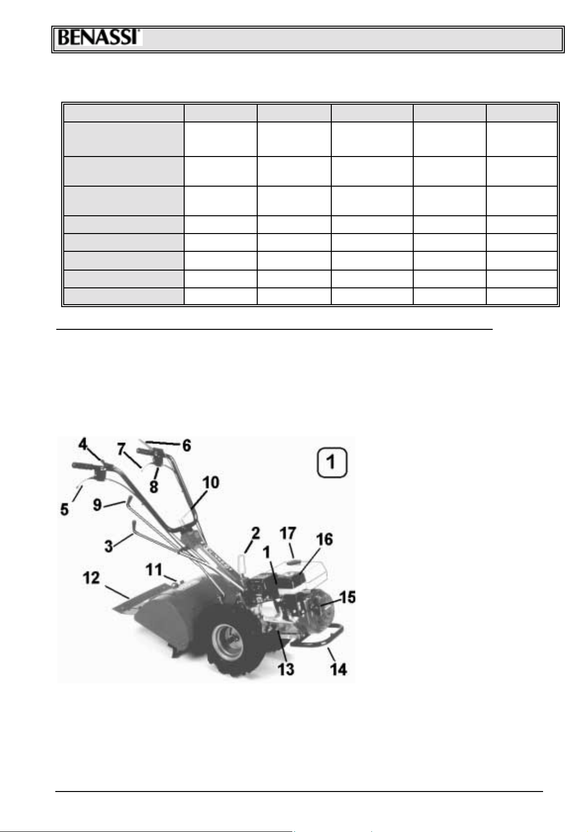
3- CHARACTERISTICS AND DRIVES CAPTIONS
1. Spark plug
2. Locking lever for handlebar mount
rotation
3. Gear lever
4. A c c eler ator hand lever
5. Wheel release lever
6. Engin e stop lever
7. Clutch lever
8. Locking pus hbutton
9. Power t ak e- off engagement lever
(cutter)
10. Loc k ing lever for handlebar
height adjustment
11. Adjustable spur
12. Adjustable hood pan el for m illing
cutter
The machine is an eng ine driven c ultivator . By c hanging tools or by turning the ha ndlebars y ou can
obtain different configurations for different uses as well.
With handlebars on the op pos ite side of the engin e ( Engin e driv en cultivat or v ers ion, Picture 2) y ou
can mount back tools (such as cutter, ploughs, listers etc.). This main version of the machine is used for
soil working. W ith handlebars tur ned on the engi ne ( Pow er mower vers ion, Pictur e 2a) y ou can mount
front tools ( central cutterbar, lawn mower, snow turbine, brush, leveller, etc.).
3
Page 4

SpA MC 2300
4 – DIMENSIONS AND OV ERALL DIMENSIONS
Engine dr iven c ultivat or ver s ion
Po wer mo wer version
5 – PACKING AND TRANSPORT
The machine is norm ally delivered pac k ed, without accessories, in carton boxes hav ing the following dimens ions and overall
dimensions:
Machin e packing : - WID TH: 47 cm.- L EN GTH cm: 71 - HEI GH T cm. 58
Mowing unit p acking : - WID TH: 38 cm.- L EN GTH cm: 40 - HEI GH T cm. 50
Acc essories are norm ally deliv ered separately from the machine; with or without pack ing.
To take the m ac hine out of t he pack ing and prepare it for work, proc eed in the following way:
a) Open and t ake the machine out of t he packing, with a second person’s help; mount t he wheels and lock them with the
suitable pin.
b) Uns c rew t he hand lev er (Ref. 10 Pic t ure 1) and mount the handlebars at the desired height .
c) F ill t he engine with oil SAE 20-40 up to t he m ark on the oil dipstick, about 0, 6 l. ( SAE 20 f or low t em perat ures, SAE 40 for
warm climates ).
d) Ass em ble the accessories (see Picture 3 accessories ).
4
Page 5

SpA MC 2300
6 - ACCESSORIES
Mowing unit
cm. 38-48
Cod. 94761600
Cut ting unit cm . 92 with special
cut t erbar and spare blade
Cod. 94564600
ALSO AVAI LABL E:
• Transfer wheel unit cod. 97063000.
• Iron wheel torque Ø 370 x 100 cod. 97063100.
• Iron wheel torque Ø 370 x 50 cod. 97063200.
• Front ballast Kg. 10 c od. 98061200.
• Coupler head cod. 91063400.
• Wheel s pacer t orque c od. 94961800.
Snow turbine cm.50
single-stage
Cod. 97561200
Single-blade lawn mower cm . 52
Cod. 96660600
Weight for mowing bar (onl y for
vers ion with YAN MAR engine)
Cod. 98061400
Wheels torque 3.50. 6
Cod. 97063300
Wheels torque 13.500.6
Cod. 97063400
Plough
Cod. 91062500
List er with arm
Cod. 91063500
Front -end leveller
Cod. 97561100
Kit f or wheels torque 3 .50.8
Cod. 97063500
Pi ct ure 3
7 -SYMBOLS and DECALCOMANIA'S
On the machine, equipment and this manual there are symbols, writings and
directions accompanied by this sign: it suggests the presence of a potential
danger. Pay attention when you see it, read carefully and keep to what it says.
Do not remove or m ak e the decalc omania's present on t he m ac hine unreadable.
It is obligat ory t o clean them when dirty and immediately c hange t hem if detached or damaged.
8 –MACHINE IDENTIFICATION
The machine identifies its elf with t he type and part number of t he gearbox. The part num ber of the engine is stam ped (when
it ex ists) by t he producer on the plate of t he engine itself or on the engine case. Ident if ication data of t he machine are carried
forward on a plate placed on t he m achine.
Report the label’s dat a of the machine on the label’s facsimile in order to hav e them alway s c los e at hand when necessary .
9 –USE OF THE MACHINE
The machine illustrated in t his manual has been made only t o be used in agric ulture and mostly f or t he ground milling.
Any us e out of t his agricult ural one is c ons idered an improper one.
The producer disclaims all res pons ibility for damages or injuries res ult ing f rom t he improper use of t he m ac hine.
The respect of the working conditions, maintenance and repairs established by BENASSI SPA, according t o the rules, are
also part of t he m achine use.
The machine c an be us ed, s ubjected t o maintenance and repaired only by someone who has prev iously read t his manual
and has been informed about its eventual dangers.
Any alt erations made on t he machine excludes responsibility by s ide of the BENASSI SPA f or the resulting dam ages.
5
Page 6

SpA MC 2300
10 – D RIVES DESCRIPTION
A) CLUTCH CONTROL LEVER is used to disengage the engine from the tr ans mission, it must be operat ed every time you operate levers and
before stopping the machine. The lever is connec ted to the ENGINE-STOP (Ref. ”B” - Pict ure 5); To ignite t he machine engage and lock the
clutch toget her with the l owered engine-stop, with the pushbutton outside the lever (Ref. “A” Picture 6). If the lever is not loc ked, the engine
will not s ta rt s ince it is eart hed. To unlock the c lutc h lever it is sufficie nt to pu ll lightly the lever upwards and t he lock ing will be automatic ally
released.
B) EN GIN E STOP L EVER the m ai n func ti on of thi s safet y d e vic e i s t o sto p i m me di atel y t h e e ngi ne i n t he mo me nt t hat on e t akes aw a y his
han ds fr o m t he han dl eb ar s a nd t o l ock t he c lutc h l e v er in eng ag ed pos it i on ( di s eng ag e me nt o f t h e e ngi ne fr o m the dr i veli n e or g ans ) i n
or der to pr event sud de n s tar t ing o f t h e mac hi ne dur i ng th e i g ni t i on ph as e of the engi ne . I f the c lut ch l e ver i s n ot l oc k ed wi t h t h e b utt on
inside the eng ine-stop in engaged position, the engine , being connect ed t o eart h, will not start. The eng ine-stop is also us ed to switch off
the eng i ne at th e e nd of the wor k.
C) ACCELERATOR HAND-LEVER permits to incr ease or decr ease th e engin e R.P.M . (power). By pushi ng it down wards cloc kwis e you
increase R.P.M.; by pushi ng it upwards countercloc kwise you decrease them.
D) W HEEL D ISEN GAG E LEV ER i s used to di seng ag e t he wh eel s f r o m tr a ns mis s ion. T hi s l ever h el ps t o m ove t he machi ne wh en s wi tched
off.
E) REVERSE LEV ER is used to reverse the machine motion; by pulling the lever in the cultivator version towards the driving place, the
mac hi ne g oes for w ar ds, b y pus hi ng i t f or war d t he m ac hi n e g oes b ac kwar ds . T h e s pe ed i n the cul t iv ator ver si on i s s l o wer th an i n the l a wn
mower version. A safet y d evice does not allow to eng age t he reverse gear when the milling cutter is in motio n. See Re f. ”A” Picture 8.
Before engaging th e revers e gear disengage the milling cutter.
F) P.T.O LE VER i s us ed t o eng ag e t h e p ower t a ke- of f to t h e di ffer en t t o ol s. B y pushi ng the l e ver f or w ar d, i n t he l a wn mo wer ver s i on, y ou
d is engage the power take-o ff, by pulling it towa rds th e driving place you engage it. In the cultiv ator version , by pushin g forwar d y ou eng age
the power take -off and by pulling the lever toward s the driving place you dis engage it.
G) HAND LEVER F OR H A NDL EBAR LOCKING is used t o adj ust the ha ndl e bar s i n t he most c om for ta bl e posi t ion to work. O nc e yo u h a ve
obtained the desired position, you have to tighten the hand lever.
H) HAND LEVER F OR STEER IN G C OLU MN LO CK IN G i s use d t o r egul at e s i d ew a ys the ha ndl e an d to 1 80° r e ver se t h e h andl e i tsel f . B y
unsc r e wi ng the h and l e ver y ou r el e as e th e s te er i ng col umn , whic h c an pi vo t; onc e you ha ve obt ai ne d t h e des ir ed pos it i o n ti g ht en strongly.
To 180° r evers e t he s t eer i ng col umn ta ke off t he r e v er s e levers a nd P .T .O a nd put the m o n agai n . T he hand l e v er i s pawl oper at e d ( s ee
hand lever for handlebar loc king ).
! FILLI NG AND VE NT OIL CAP (Ref. ”A” - Pict ure 7 ).
! DISCHARGE G EARBOX OIL CAP. (Ref. ”A” Picture 14)
! LEVEL OIL SCREW ( R ef. “B” Pi c tur e 7)
11- TOOLS MOU NTING AND MACHINE REVERSIBILITY
! It is very easy to mount or t o c hange tools to the machine. Tools are all quic k coupling type and don’t need screws or fastening spanners
for the locking.
! Tools ar e coupled in the machi ne body (male and female) and locked wit h a pin. T he pin must be locked with the l ever (Ref. “B” Picture
8) in order to avoid its disengagement.
! Assure that the t ool part (male) to coupl e in the machine body is always well lubricated.
! T o tur n t h e h andl eb ar st eer i ng col umn fr o m th e C ul ti vat or ver s i on ( b ac k tool s) t o t he Po wer m o wer ver s i on ( fr on t t o ol s) pr oc ee d in the
following way:
1) T ake off th e s pe ed s el ec t or l e vers PT O c om plet el y , uns cr e w the han d l e ver steer i ng col umn ( Ref . “ H ” Pi ct ur e 5) , tur n 180° t he s te er i ng
colum n counterclockwis e, tighten thoroughly the hand lever and i nsert the levers again, not forgetting t o loc k them wit h its cot ter pins,
making t hem pass through the two hol es with fairlead on the left of the handle support.
2) Take off the safety locking rod for reverse gear, (Ref. “A” Picture 8), slippi ng off the two s peci al cotter pi ns, (Ref. “C” Picture 8).
! T o pas s fr om the P ower m ower v er s ion t o t he C ul ti vat or ver s i on pr ocee d i n the s am e w ay, tur ning clockwise t he s t eer i ng col um n. Put
the safety locking rod for reverse gear again, (Ref. “A” Picture 8).
6
Page 7

SpA MC 2300
ATTENTION:
When you turn the steering column you have to turn the wheels as
we ll : the Righ t to the Left, the Le ft to the Right. Pic ture 9 shows the
correct position (see groove)
Pi ct ure 9
12 MACHINE ST ARTING
BEFORE USING THE MACHINE MAKE SURE Y OU LEA RNT HOW TO STOP
IT ; IN CASE OF BREAKDOWN OR NECESSITY TAKE IMMEDIATELY THE
Before starti ng the machine alway s control :
! the oil levels in the engine wit h the proper oil dips tick and in the gear box by means of the suitable screw ( make this onl y when the
machine is new and every 50 hours );
! that in t he air-filter (if in oil bath) oil reaches the reference notch;
! that t yres have the right press ure ( Atm. 1, 3) and are c orrectly oriented (see Picture 9 );
! that all screws and nuts are well fastened;
! that all levers are in neutral position;
! that the clutc h lever has some freeplay;
! that there is fue l in the tank, the refue lling must be done with a funnel comp lete of filt er in order to avoid the introdu c tion of impurit y;
! Before starting the m achin e m ake sur e there ar e not walls or obstacles behind you .
To start the ma chine pro ceed in the follo wing way :
1) Eng age th e c l utc h, ( R ef . “ A” Pi ct ur e 5) , l o wer th e E NG IN E ST O P lever, ( Ref . “ B” Pi c tur e 5) and l ock bot h wi th th e r ec tang ul ar pus hb ut t on
inside the l eft handle, (Ref. “A” Picture 6) (ENGINE STOP device).
2) C l ose the ai r to t he car bur ettor ( s tar ter ) , o pe n the f u el coc k, pos i ti on the ac c el er ator ha nd l ever, ( R ef . “ C ” Pi c tur e 5) , at ½ gas and pull
vigorousl y the rope of the ignition, (Ref.”15” picture 1). When the engine is running release the st arter.
3) Wa rm up the engine for some minutes before starti ng to work.
When the engine is new, make some runni ng in period.
LEF T HAN D AWAY F ROM THE HANDLE (E NGI NE STOP).
13 – START OF THE WORK
Accurately inspect the wor k area, removing foreign objects ( iron wires, stones, stic ks, glasses etc.), sinc e t hey coul d cause dangerous and
sudden r eactions of the machine.
Engage the clutch , the ENGINE STOP pushbutton will release its elf, then put into ge ar and po wer t ake-off, g i ving l i tt le c l utc h- t ouc hes i f i t
does not i mmediatel y engage.
Accelerate opportunel y the engine and rel ease the clutch to start wor king.
ATTENTION If the power take-off is engaged, you cannot engage the rev erse gear. I n this case dis engage the power
tak e-off and then engage t he rev erse gear. I t is imposs ible to ins ert the milling c utter when the reverse gear is engaged.
14 – END OF THE WORK
Once you have ended your wor k, to stop the engine close the fuel cock and push the STOP ENGINE button or release the ENGINE STOP
leve r. (Re f. ”B” Pic tu re 5 ).
15 USE OF THE MACHINE – MILLING UNIT R EVERSIBILITY
The princi pal us es of the machine are:
C ult i vator ver si o n (S ee Pi c tur e 2) ;
Po wer mo wer v er si on (S ee P ic tur e 2a) .
7
Page 8

SpA MC 2300
IM PO RTANT :
Before doing the ope rations descri bed be l ow, switc h off the engine.
The milling unit (Picture 11) can b e mounted so that the mo wing rotation corr esponds to t he advan cing wh eel rotation or
contrary to it. See the dart indic ation on the mowing uni t side .
To ch an ge t h e ro t at io n t ake o ut t h e hood panel for milling cut ter u nscre wing th e two bolt s (R ef. “ A” Pict ure 10) and t he bo lt
(Ref. B Picture10).
Slip t he milling t ransmi ssion u nit of f by pu lling th e lever ( Ref . B Pict ur e 8), remov e t he spur ( R ef. A Picture 11), t akin g o ff the
bolt (Ref. A Picture 11) and mount it again upside-down. Then mount the hood panel for milling cutter again on the
transmission unit upsid e-down making al l the inver se process .
Th e milling cut t er hood panel can en able, through two adjustable sid es (Ref. “B” and “C” Picture 11) two working width, cm.
40 and 50.
In the narro wer v ers ion, the milling blades of the external cutters have to be scr e wed and turned in wards (Ref. ”D” Picture11).
16 MAINTENANCE AND L UBRICATION
A g ood mai nte nance a nd a perf ect l ubricati on are b oth necess ary oper ations to keep yo ur mac hine p erfectl y ef ficient . The machin e is
nor m al ly del ivered packed and wit ho ut engi ne oi l , as i t is in di c ate d on t he n ot e ap pl i ed to the e ngi ne.
ENGINE
Plea s e follow the s pecific “ENGI NE USE A ND MAI NT ENA NCE” boo kl et pr o vide d wi th th e mac hi ne for i ns tr uc ti o ns , us e and mainte nanc e of
the eng i ne .
It i s a g ood r ul e t o c on t r ol t he oi l l evel e ver y 5 hour s of w or k an d to c h ang e i t e ver y 50 h our s . U s e oil SAE 40 i n s u m mer a nd SAE 20 in
winter. The first oil c hange must be done after 10 hours of work.
C ontr ol t hat the ai r - fi l ter i s cl ean, i f t he f i lt er i s i n oi l b at h c o ntr ol the l e vel e very 8- 10 ho ur s of work or e ve n mor e fr eque ntl y if you ar e
working in dust y grounds. Use engine oil to restore the oil level; before r efilling the oil t ank, wash it carefully.
GE AR BO X
Control the oil level every 50 hours of work by taking out the cap on the gear box case (t he machine must be in the horizontal position).
I f neces sary, ad d oi l SAE 80-90. It is suggested to change oil at least onc e a year . To empt y the oil in the gear box, unscrew the cap of the
i nfer i or par t of t he b ox (R ef. “ A” Pi ct ur e 14) , take out t he oi l c ap ( R ef. “ A” pi c tur e 7) t o all ow the oi l f l o wing out mor e e as ily. Put t he inf erior
cap again and fill w ith oil thou gh the cap (Ref. ”A” P ic ture 7) up to the sc rew lev el (Ref. “B” Picture 7).
MILLING CUTTER
Before st arting to work , control that all screws are well fastene d, espe c ially those of the mill hoes.
Co ntrol the oil level of the milling cutter transm is s ion unit every 10 0 hours of work , by taking out the cap on the lid (Ref. “ E” Pi c t ur e 11) . Oi l
m ust fill almost completely the gearbox cas e. Use SAE 80- 90 oil.
CUTTERBAR
! Before starti ng to work, control that all screws are tight fastened.
! Every 4 hours of work lubricate the i nside of the blade head.
! Every 10 hours of wor k lubricate the eccentric ferrule - (Ref. “A” Picture 12).
! Every 20 hours of wor k lubricate the linkage between the cutt erbar and the machi ne.
! Periodicall y is needed to control bl adeholders (Ref. “B” Pict ure 12) s o that the blade has not too much freeplay or is f astened too tight. If
the cutting of the grass aft er the adjust ments is not satisfying, the blade needs to be grinded or changed.
8
Page 9

SpA MC 2300
17 -G ARAGING
Before gara ging the machine:
! Wash it carefully with Diesel fuel, chan ge the engin e oil, gea r box and m illing unit .
! Empt y the fuel tank and wash or change the air-filter.
! Oil and lubricate ever y joints and mechanism.
! Change or repair eventual damaged parts.
! Park the mac hine i n a dr y room, putting its wheels on wooden boards or, even bet ter, lifted from the ground.
18 - TR OUBLESHOOTING
Event ual troubles which can be sol ved by the operator ( worker) :
ENGINE :
The engine doesn’t start; c ontr ol that:
! Fuel in the tank reaches half of the t ank its elf .
! The fuel cock is open.
! The starter must be engaged if the engine is cold.
! Fuel arrives t o t he c arburettor.
! The vent c ap on the t ank is not clogged.
! The car buret tor cas tings are open; other wise clean them wit h compressed air.
! The ignit ion spark works : to te s t this , un s c rew the s pa rk plu g, reconne ct it to th e e lectric ca ble, lean the metallic pa rt of the spar k plug to
mass ( wor king c ylinder) and turn the engine pulley as for the starti ng . If the ignition spar k does not s par k among the electrodes , control
the j oi n ts of the el ectr i c cabl e. O t her wis e chang e t h e spar k pl ug wit h a not her o ne . I f e ven t hi s attem pt fai l s, the br eakd o wn has to be
attr i buted t o the l i g ht i ng set ( poi nts , c apac it or , c oil s etc .) . I n thi s cas e w e sugg es t to a ppl y to t h e n ear es t ser vic e r elati ng the engine
mo unt ed on t h e m ac hine.
GEARS DO NOT ENGAGE :
! Regulate the clu tch by unscrew ing the register screw (Ref. “B” P ic ture 6) till yo u obtain a good c lutch disenga gem ent.
! Pay attention: do not elimi nat e t otall y the freeplay.
! The clutch wire must not be complet ely engaged.
19 – RULES FOR A CORRECT USE OF THE MA CHINE
! Make a good r unni ng in period to the engine and the machine (for at l east 10 hours do not get over 70 % of the engine c apacit y ).
! Always use the clutc h before oper ating any levers.
! Do not leave the cl utch disengaged f or a l ong time.
! Never force the speed selector levers and PTO, if they do not engage l eave gradually the clutch.
! Keep the steering col umn joint and the handlebar cleaned and oiled.
! Never force the engine; when smoke comes out from the exhausting pipe, it means that the engine is under stress .
! Do not wor k for long periods of ti me at full speed, in partic ular during war m periods.
! Periodicall y control the tyre pressure ( Atm. 1,3)
! D ur i ng the m ounti ng of t he di ffer ent tool s do no t damag e the do wel s ( R ef . ” D ” Pi ct ur e 8) an d t h e spl i nes , con t r ol th at s c r e ws and the
fastening spine of the to ols are well lo cked, especially s c rews of th e mill hoes and the faste ning sc rews of the cut te rbar.
! Do not leave the machine under the rain.
20 – ACCIDENT-PREVENTION RULES
ATTENTION, IT IS DANGERO US :
! To leave the engine r unning in clos ed rooms; exhaust gases are highly toxic.
! To refuel with the engine running or overheat ed.
! To accel erate going to reverse; the engine must be at mi nimum speed.
! To make tests, to clean and to r epair tools ( millin g cutt er, cut terba r, lawn mower etc .) with the engine runnin g.
! To touch the just switched off engine (some parts may burn).
! To move with the c utter bar without prot ection.
! To e xec ute th e opera tions of trans port, mainte nance, r epair and l ubricati on with the eng ine n ot s witc hed off a nd with out all t he
pr otec ti ons mo un ted.
! On mea ns of transpor t th e mac hi ne mus t be w el l fasten ed wi th pro per locking .
! T he cut t er pr ot ec t i ons mus t b e adj ust e d acc or di ng to t he d ept h of th e w or k , so t hat t he par t of t h e tool whi ch c u t s t he g r oun d remains
uncovered; never make hoeing oper ations without t he back hood panel on the machine.
! Keep al ways efficient the safet y dispos als ( above all the automatic engine s top ) and the protections of the rotating elements.
! Bef or e star ti ng to wor k ma k e s ur e t her e ar e not per s o ns or obs tac l es i n the mac hi ne rang e of act ion i nfer i or to 5 meter s.
! Wear proper shoes and clothes, do not wear large or fluttering clot hes (scarf or f oulard).
! N ev er wor k i n sl opi ng g r ounds wit hou t ha vi ng as sur ed the m ac hine s ta bility. Attention! Do not work in grounds with a more than 50 %
slope.
! Keep the f uel i n proper t anks.
9
Page 10

SpA MC 2300
0
! The refu elling must be done in airy plac es, wit h the engine s witched off and col d. D ur i ng thi s oper ati on do not s mo k e, i f t he fu el c om es
out (especially petrol) dr y the wet parts and if possi ble blow away wit h compressed air, move the machine in a dr y place before starti ng
it.
! To mo ve the machi n e fr om a w or k g r oun d to an a nother o ne or dur i ng the r evers e ma noe uvres , b ef or e s tar ti ng t h e w or k agai n al w a ys
disengage the power take-off to s top the moving organs.
! The was te di sposal of lubr i cat or s and batt er i es m ust b e d one i n confor mit y wit h t he r ul es i n for c e i n t he c ountr y w her e t he machi ne is
used.
! Before leaving the machi ne, disengage the power take-of f, st op the engine and take away the plug spar k cap.
! Read car efully the Use and Mai ntenance booklet provide d with the machine.
! The use of t he machine is forbidden to persons under 16 .
! The operator is responsi ble for the damages, since he is the dri ver of the machine.
! Dry the petrol leakage.
! Refill the tank with the engine switched off. Th e refu elling and/or the f u el po ur i ng off mus t alw ays be d on e out si de, f ar f r om fi r e or he at
sources. Do not smoke during t his operati on.
! Before starti ng t o us e th e eng i ne dr iven culti vator, i t is nec essar y to l earn ho w to r a pidl y switc h t he engi ne off, to fa miliarise wit h the
drives and t o learn how to properl y use the machine. Do not make the engine run where outlets with carbonic oxide c ould accumulate.
! We di sclaim all respons ibilit y for incidents caused by non-observanc e of these r ules.
ATTENTION: during the continuative use of the machine the
use of hear ing pr otect ion device s is recom m ended.
21 CE DECLARATION OF THE MACHINE
CE Declaration of conformity according to CEE Directives CEE 89/392 and following modifications.
CE De clar ation of conformity accor di ng to CE E directi ves 89 /392 and following modi fica tions.
40010 S an Matteo della Deci ma BO Italy Via Lampedusa n° 1
W e dec lare under our sole respo nsibility th at the m achine is in con formity wit h the essen tial safety and health p rotect ion requirements
according t o CEE 89/392 Directi ve and its following modifications .
TYPE ENGINE DRIV EN CULTIVATOR MODEL MC 2300
For the conformity tes t acc ording to the Directi ves mentioned above, the following regulati ons have been consult ed : PREN 709/94 of 16/06/94.
MA NAGING DIRECT OR
S. Matteo della D ecima li 26/11/98
TYPE ENGINE DRIVEN CULTIVATOR MODE L MC 2300 “REV ERSO”
Sound pressure at the operator’s ear : LAeq = 93 dB (A)
Tes t c onditions : h ei ght1,6 M t handlebar centre
H andlebar vibr a t i on wit h I SO.534 9 as ses sme nt value 19,6 m/s ec2
RESULT AND TEST S
S.p.A.
VIA LAMPEDUSA 1
40010 S. MATTEO DELLA DECIMA (BO ) - ITALY
TE L. 0039/051/82.05. 34 TELEF AX 0039/051/ 682.6 1.64
Retailer stamp
1
 Loading...