

Page 1
1/2006 1
TP 300-4517-00-RG-SMAN
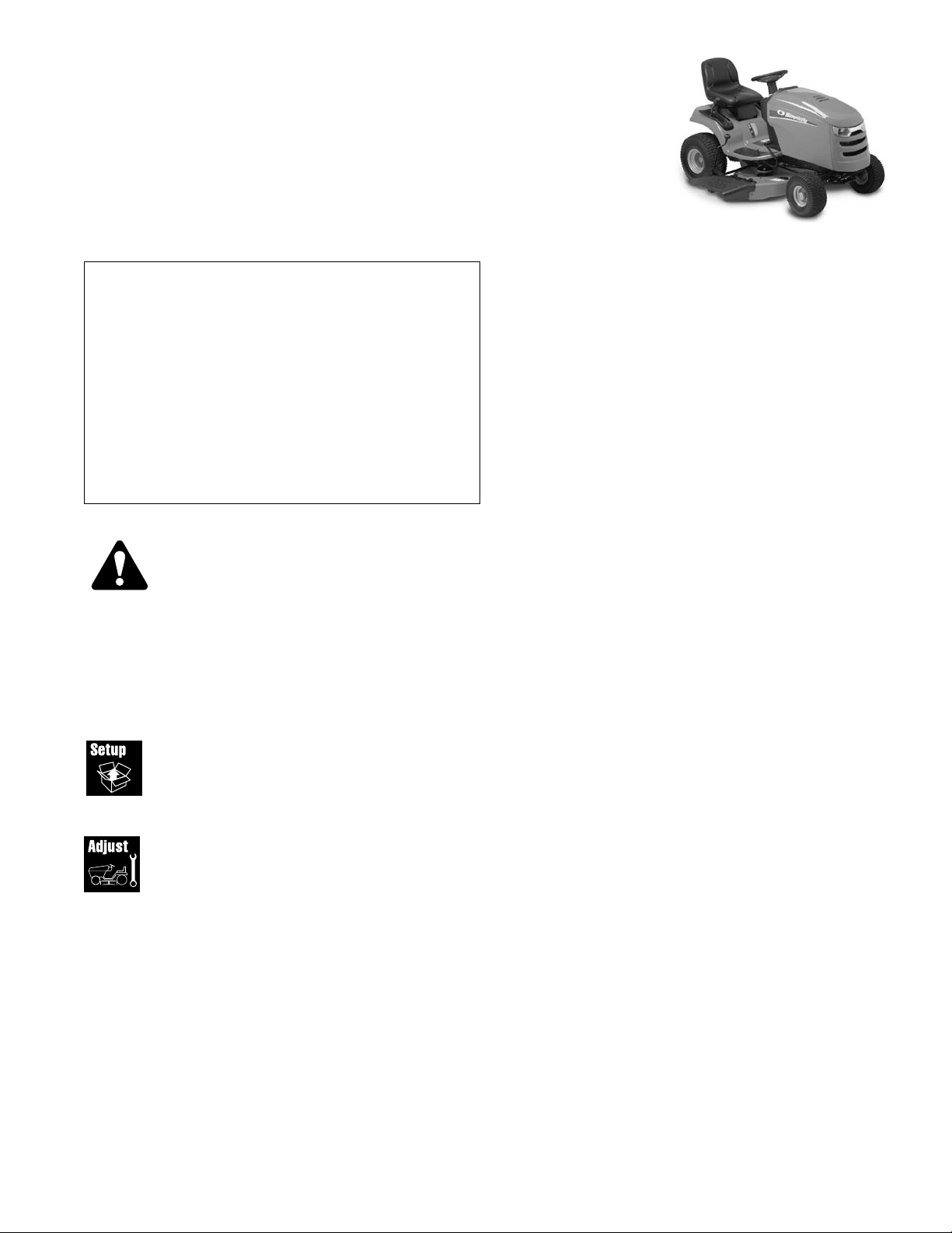
Setup
& Adjustment Instructions
LT-200 Series Tractors and Mowers
TABLE OF CONTENTS:
SAFETY RULES .................................................................2
SETUP PROCEDURES
Quick Setup List ................................................................3
Uncrating............................................................................4
Battery Charging & Installation........................................4
Check Fluid levels .............................................................5
Check Transmission Oil Level .........................................5
Fill and Check Engine Oil.................................................5
Perform Safety Checks .....................................................6
Functional Tests...............................................................6
Mower Blade Stopping Check..........................................6
Seat Switch Connection...................................................6
Safety Interlock System ...................................................6
Torque Mower Blades .......................................................7
Burnishing the Electric PTO Clutch.................................7
Reduce and Check Tire Pressure ....................................7
Lubrication .........................................................................8
Hourmeter ........................................................................11
Mower Adjustments & Assembly...................................10
Mower Deck Removal & Installation ..............................10
Side-to-Side Leveling.....................................................11
Front-to-Back Leveling...................................................11
ADJUSTMENT PROCEDURES
Adjust Gauge Wheels......................................................12
Seat Slide Adjustment.....................................................12
Electric PTO Clutch Adjustment ....................................13
SERVICE PROCEDURES
Mower Belt Replacement ................................................14
Attention Setup Personal:
Sections and items denoted by the Setup symbol
provide the information necessary to fully assemble,
test, and prepare the units described above for
delivery to your customers.
Additional information concerning functional tests,
general adjustment procedures, and the location of
normal lubrication points are included in these
instructions.
The safety warnings provided in this guide and in
the operator's manual included with the unit contain
important information that must be obeyed when
assembling, setting-up, operating, servicing,
transporting, or storing the unit.
These warnings are highlighted by the safety alert triangle
symbol shown above, which signifies that an important safety
message is being provided.
You must read, understand, and follow these warnings and
instructions, and use safe shop and work practices at all
times while working on or around this unit and all other
outdoor power equipment.
Mfg. No.Description
Tractors & Mower Combinations
2690437 LT-200, 20HP & 44” Mower Deck
Form No. 1734713-00
Page 2

LT-200 Series
TP 300-4517-00-RG-N 3/20072
Read these safety rules and follow them closely. Failure to obey these rules could result in loss of control of equipment, severe
personal injury or death to you, yourself or bystanders, or damage to property or equipment. This mowing deck is capable of
amputating hands and feet and throwing objects. The triangle in text signifies important cautions or warnings which must be
followed.
IMPORTANT – Safe operation practices for riding mowers.
I. General operation
1. Read, understand, and follow all instructions in the manual and on
the unit before starting.
2. Only allow responsible adults, who are familiar with the
instructions, to operate the unit.
3. Clear the area of objects such as rocks, toys, wire, etc., which
could be picked up and thrown by the blade(s).
4. Be sure the area is clear of other people before mowing. Stop the
unit if anyone enters the area.
5. Never carry passengers.
6. Do not mow in reverse unless absolutely necessary. Always look
down and behind before and while backing.
7. Be aware of the mower discharge direction and do not point it at
anyone. Do not operate the mower without either the entire grass
catcher or the guard in place.
8. Slow down before turning.
9. Never leave a running unit unattended. Always turn off blades, set
parking brake, stop engine, and remove keys before dismounting.
10. Turn off blades when not mowing.
11. Stop engine before removing grass catcher or unclogging chute.
12. Mow only in daylight or good artificial light.
13. Do not operate the unit while under the influence of alcohol or
drugs.
14. Watch for traffic when operating near or crossing roadways.
15. Use extra care when loading or unloading the unit into a trailer or
truck.
II. Slope operation
Slopes are a major factor related to loss-of-control and tip-over
accidents, which can result in severe injury or death. All slopes require
extra caution. If you cannot back up the slope or if you feel uneasy on
it, do not mow it.
DO
• See your authorized dealer for recommendations of wheel weights
or counterweights to improve stability.
• Mow up and down slopes, not across.
• Remove obstacles such as rocks, tree limbs, etc.
• Watch for holes, ruts, or bumps. Uneven terrain could overturn the
unit. Tall grass can hide obstacles.
• Use slow ground speed so that you will not have to stop or change
speeds while on the slope.
• Use extra care with grass catchers or other attachments. These
can change the stability of the unit.
• Keep all movement on the slopes slow and gradual. Do not make
sudden changes in speed or direction.
• Avoid starting or stopping on a slope. If tires lose traction,
disengage the blade(s) and proceed slowly straight down the
slope.
DO NOT
• Do not turn on slopes unless necessary, and then, turn slowly and
gradually downhill, if possible.
• Do not mow near drop-offs, ditches, or embankments. The unit
could suddenly turn over if a wheel is over the edge of a cliff or
ditch, or if an edge caves in.
• Do not mow on wet grass. Reduced traction could cause sliding.
• Do not try to stabilize the unit by putting your foot on the ground.
• Do not use grass catcher on steep slopes.
III. Children
Tragic accidents can occur if the operator is not alert to the presence
of children. Children are often attracted to the unit and the mowing
activity. Never assume that children will remain where you last saw
them.
1. Keep children out of the mowing area and under the watchful care
of another responsible adult.
2. Be alert and turn unit off if children enter the area.
3. Before and when backing, look behind and down for small
children.
4. Never carry children. They may fall off and be seriously injured or
interfere with safe unit operation.
5. Never allow children to operate the unit.
6. Use extra care when approaching blind corners, shrubs, trees, or
other objects that may obscure vision.
IV. Service
1. Use extra care in handling gasoline and other fuels. They are
flammable and vapors are explosive.
a) Use only an approved container.
b) Never remove gas cap or add fuel with the engine running.
Allow engine to cool before refueling. Do not smoke.
c) Never refuel the unit indoors.
d) Never store the unit or fuel container inside where there is an
open flame, such as a water heater.
d) Clean up oil and fuel spills immediately.
2. Never run a unit inside a closed area.
3. Keep nuts and bolts, especially blade attachment bolts, tight and
keep equipment in good condition.
4. Never tamper with safety devices. Check their proper operation
regularly.
5. Keep equipment free of grass, leaves, or other debris build-up.
6. Stop and inspect the equipment if you strike an object. Repair, if
necessary, before restarting.
7. Never make adjustments or repairs with the engine running.
8. Grass catcher components are subject to wear, damage, and
deterioration, which could expose moving parts or allow objects to
be thrown. Frequently check components and replace, when
necessary, with manufacturer’s recommended parts.
9. Mower blades are sharp and can cut. Wrap the blade(s) or wear
gloves, and use extra caution when servicing them.
10. Check brake operation frequently. Adjust and service as required.
11. Allow the unit to cool before storing.
WARNING – SLOPE OPERATION
Never operate on slopes greater than 17.6 percent (10°) which is a
rise of 3-1/2 feet (106 cm) vertically in 20 feet (607 cm) horizontally.
When operating on slopes that are greater than 15 percent (8.5°)
but less than 30 percent use front counterweights and rear wheel
weights (see your dealer). Select slow ground speed before driving
onto slope. In addition to front and rear weights, use extra caution
when operating on slopes with rear-mounted grass catcher. Mow
UP and DOWN the slope, never across the face, use caution when
changing directions and DO NOT START OR STOP ON SLOPE.
SAFETY RULES
Page 3

LT-200 Series
3/2007 3 TP 300-4517-00-RG-N
Quick Setup List -
Page Setup Procedure Steps to Perform
4 Uncrating
o Remove Crate & Banding.
o Place Transmission Release Lever in PUSH position & Roll
Tractor forward off skid.
4 Battery Charging & o Charge the Battery
(Note: proceed with other setup steps
Installation
while battery is charging).
o Install Battery.
5 Check Fluid Levels o Check Transmission fluid level.
o Fill & check Engine oil level.
6 SAFETY CHECKS o Check for LOOSE HARDWARE.
o
Check all OPERATOR CONTROLS.
o Test PARKING BRAKE.
o Perform MOWER BLADE STOPPING CHECK.
(Blade must stop within 5 seconds!)
o Check the Seat Switch connection.
o Perform SAFETY INTERLOCK SYSTEM CHECK.
7 Torque Mower Blades o
Torque mower blades to 45-55 ft.lbs. (61-75 Nm.
7 Burnish Electric Clutch o Burnish Electric Clutch
(run for 15 seconds, repeat 10
times)
.
7 Reduce &
Check Tire Pressure
o Reduce & check Tire Pressure.
(Front Tires 12-15 psi, Rear tires 10-12 psi)
8 Lubrication o Lubricate all grease & oil points.
10 Mower Assembly o Install Mower Deck onto Tractor and Attach Belt
o
Level Mower Deck (Side-to-side & Front-to-back).
14 Adjustment Procedures o Gauge Wheels.
Page 4
LT-200 Series
TP 300-4517-00-RG-N 3/20074
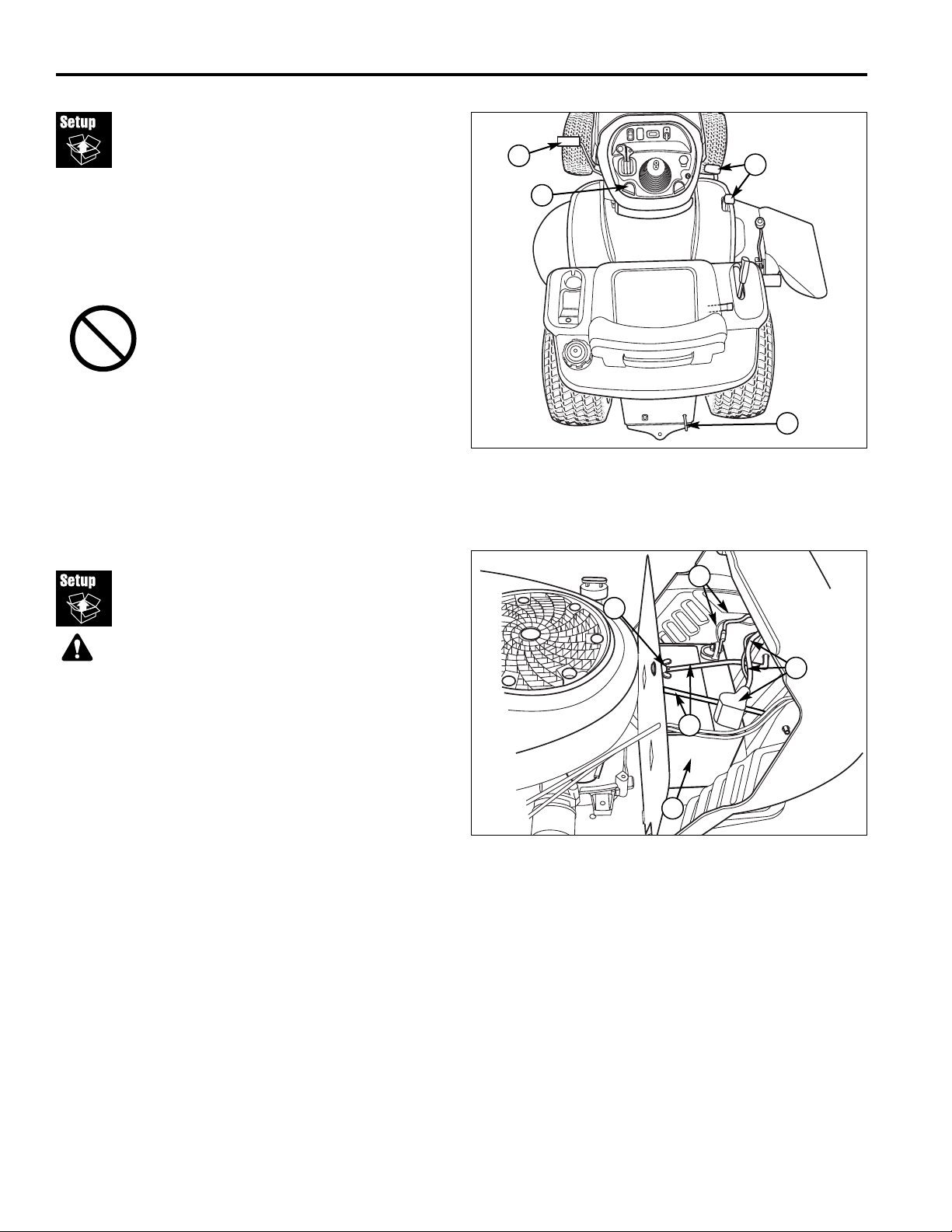
Uncrating
Using a reciprocating utility saw or equivalent, cut crate
away from bottom skid. Remove crate. Remove shrinkwrap plastic.
2. Cut banding from front and rear tractor axles. Cut
banding from mower rollers. Remove mower from
bottom skid.
3. Hold brake pedal down (B, Figure 1) and push down
on parking brake knob (C) to release parking brake.
4. Place hydro release lever in the PUSH position by
pulling the release lever handle (D) back until it locks
in the released position.
5. Be sure there are no nails or sharp objects on bottom
skid to puncture the tractor’s tires. Roll the tractor
forward off the skid.
IMPORTANT NOTE
When cutting crate from bottom skid, use
caution around tractor tires and mower
rollers.
Battery Charging &
Installation
Charge Battery
1. Open the tractor hood to access the battery (E, Figure
2).
2. Loosen the wingnut & washer (D).
3. Pivot the hold-down rod (C) up and away from battery
and secure.
4. Remove the battery (E).
2. To charge the battery, follow the instructions provided
by the battery charger manufacturer as well as all
warnings included in the safety rules section of this
document. Charge the battery until fully charged. Do
not charge at a rate higher than 10 amps.
WARNING
BATTERY SAFETY RULES
• Battery acid causes severe burns. Avoid contact
with skin.
• Wear eye protection while handling the battery.
• To avoid an explosion, keep flames and sparks
away from battery, especially while charging.
• When installing battery cables, CONNECT THE
POSITIVE (+) CABLE FIRST and negative (-) cable
last. If not done in this order, the positive
terminal can be shorted to the frame by a tool.
Figure 1. Engaging the Parking Brake
A. Ground Speed Pedals
B. Brake Pedal
C. Parking Brake Knob
D. Hydro Release Lever
B
C
A
Figure 2. Battery Maintenance
A. Negative Cables
B. Positive Cables & Cover
C. Hold-Down Rod
D. Wingnut & Washer
E. Battery
D
C
E
Install Battery
1. Reinstall the battery (E) in the battery compartment,
and secure with the battery hold-down rod (C) and
wingnut & washer (D).
2. Reattach the battery cables, positive cables first (B)
then the negative cables (A).
3. Coat the cable ends and battery terminals with
petroleum jelly or non-conducting grease.
A
B
D
Page 5

LT-200 Series
3/2007 5 TP 300-4517-00-RG-N
Check Fluid
Levels
Check Transmission Oil Level
The K46 transmission is a sealed unit that is shipped with
the correct oil level. However if a transmission’s oil level
is suspect it can be checked. See Transmission
Maintenance.
Fill & Check Engine Oil
Service Interval: Before each use, and every 8 hours.
1. Turn the engine off, and set the parking brake to
PARK.
2. Clean the area around the dip stick (C, Figure 3).
3. Remove the dip stick (C) and clean it with a paper
towel.
4. Insert the dip stick (C) back into the engine and
thread the cap back onto the tube.
5. Remove the dip stick and read the oil level. The oil
level should be between the “FULL” and “ADD” marks
(D). If not, add oil according to the oil
recommendations chart (Figure 39 or 40).
Figure 3. Briggs & Stratton two cylinder Models
A. Oil Drain Valve
B. Oil Filter
C. Dip Stick
D. Checking Oil Level
A
C
D
B
Page 6

LT-200 Series
TP 300-4517-00-RG-N 3/20076
Figure 4. Seat Switch
A. Seat Switch
B. Wiring Harness
Perform
Safety Checks
Functional Tests
1. Check the tractor for loose bolts, screws, nuts, etc.
2. Start the engine and check all controls for proper
operation: ground speed control pedals, clutch/brake
pedal, parking brake, throttle and choke cables, electric
PTO clutch, headlight switch, steering, attachment lift,
etc.
3. Stop the engine and check for fluid leaks: oil, gasoline,
or transmission oil.
4. If any control fails to operate properly during testing or
seems to be out of adjustment, check and readjust it
according to the following Adjustments section.
Mower Blade Stopping Check
Mower blades and mower drive belt should come to a
complete stop within five seconds after the electric clutch
switch is turned off.
With the tractor in neutral, the electric clutch switch
disengaged, and an operator in the seat, start the tractor
engine. Run the engine at full throttle. Engage the electric
PTO clutch switch and wait several seconds. Disengage
electric clutch switch and check the time it takes for the
mower drive belt to stop. If the mower drive belt does not
stop within five seconds, adjust the PTO clutch according to
the instructions in the Electric Clutch Adjustment section.
Seat Switch Connection
Check that the seat switch (A, Figure 4) is connected to
the seat switch wire harness (B).
WARNING
Disengage the PTO, stop the engine, set the parking
brake, and wait for moving parts to stop before
leaving operator's position for any reason.
If the tractor does not pass the test, do not
operate tractor. Under no circumstance should
you attempt to defeat the purpose of the safety
system.
A
B
Safety Interlock System
Tests
This unit is equipped with safety interlock switches and other
safety devices. These safety systems are present for your
safety: do not attempt to bypass safety switches, and never
tamper with safety devices. Check their operation regularly.
Operational SAFETY Checks
Your unit is equipped with a seat switch safety system.
Check the seat switch operation every fall and spring with the
following tests.
Test 1 — Engine should NOT crank if:
• PTO switch is ON, OR
• Brake pedal is NOT fully depressed (parking brake OFF),
Test 2 — Engine SHOULD crank if:
• PTO switch is OFF, AND
• Brake pedal is fully depressed (parking brake ON)
Test 3 — Engine should SHUT OFF if:
• Operator rises off seat with PTO engaged, OR
• Operator rises off seat with brake pedal NOT fully
depressed (parking brake OFF).
Test 4 — Blade Brake Check
Mower blades and mower drive belt should come to a
complete stop within five seconds after electric PTO switch is
turned OFF (or operator rises off seat). If mower drive belt
does not stop within five seconds, re-adjust the PTO clutch
as described in the ADJUSTMENTS section or see your
dealer.
Test 5 — Reverse Mow Option (RMO) Check
• Engine should shut off if: PTO is engaged AND RMO is
not activated AND reverse pedal is depressed.
• RMO light should illuminate if: RMO is engaged AND
PTO switch is activated.
NOTE: Once the engine has stopped, the PTO switch must
be turned off after the operator returns to the seat in order to
start the engine.
WARNING
If the unit does not pass a safety test, do not
operate it. See RMO Switch Adjustment. Under
no circumstance should you attempt to defeat
the purpose of the safety interlock system.
Page 7

LT-200 Series
3/2007 7 TP 300-4517-00-RG-N
Figure 5. Blade Torque
A. 4x4 Wood Block
B. Spline or Hex Washer
C. Spring Washer
D. Blade Bolt
Torque Mower Blades
1. Secure the hex washer (B, Figure 5), spring washer
(C) and capscew (D). Use a wooden block (A) to
prevent blade rotation while tightening the blade bolt
(D) to 45-55 ft. lbs. (61-75 Nm).
WARNING
For your personal safety, do not handle the sharp
mower blades with bare hands. Careless or
improper handling of blades may result in serious
injury.
WARNING
For your personal safety, blade mounting
capscrews must each be installed with two spring
washers or a hex washer and spring washer, then
securely tightened. Torque blade mounting
capscrew to 45 - 55 ft. lbs. (61 - 75 Nm).
A
B
C
D
Burnishing the Electric
PTO Clutch
1. Select a safe area to operate the mower deck. With
the drive in neutral, the PTO switch disengaged, and
an operator in the seat, start the tractor engine. Run
the engine at full throttle.
2. Engage the PTO switch and run the deck for fifteen
seconds. Disengage the PTO switch and wait for the
mower drive belt to stop.
3. Repeat step 2 above ten times, and then re-check the
mower blade stopping time. (Stopping time must be
five seconds or less.)
Reduce & Check Tire
Pressures
The tires are over-inflated for shipping purposes. Inflate
to the pressures shown. Note that these pressures may
differ slightly from the “Max Inflation” stamped on the
side-wall of the tires. The pressures shown provide
proper traction, improve cut quality, and extend tire life.
Figure 6. Tire Pressure
Size PSI bar
22 x 1.0-8 10 0.68
15 x 6.0-6 12-14 0.82-0.96
Page 8

LT-200 Series
TP 300-4517-00-RG-N 3/20078
Lubrication
Lubricate the unit at the locations shown in Figures 7-10
as well as the lubrication points listed. Generally, all
moving metal parts should be oiled where contact is
made with other parts. Keep oil and grease off belts and
pulleys. Wipe surfaces clean before and after
lubrication.
Grease:
• steering linkage
• mower linkage
• front axle shafts (remove wheel hubs)
• rear axle shafts (remove wheel hubs)
Use grease fittings when present. Automotive
lithium grease is recommended.
Oil:
• foot pedal rods & brackets
• seat adjustment assembly
• draglink
• mower deck height adjustment linkage
• manual lift lever
• transmission idler assembly
Figure 7. Lubricating
Page 9

LT-200 Series
3/2007 9 TP 300-4517-00-RG-N
Figure 8. Mower Lubrication Points
Figure 10. Arbor Lubrication Point
Figure 9. Mower Lubrication Points
Hourmeter
HOURMETER MODELS
The hour meter measures the number of hours the key
has been in the RUN position. This hourmeter can not
be reset and does not have a maintenance reminder.
1/10
HOURS
Figure 11. Hourmeter - Select Models
Page 10

LT-200 Series
TP 300-4517-00-RG-N 3/200710
Mower Deck Removal &
Installation
Removing the Mower Deck
1. Park tractor on a hard, level surface such as a
concrete floor. Turn off PTO switch and engine,
remove the key and apply parking brake.
2. Place wood blocks under the mower deck. Place the
attachment lift in the lowest position.
3. Move idler arm (A, Figure 13) to relieve belt tension.
Remove belt from PTO pulley (B).
4. Remove hair pin (D, Figure 12) and washer (C).
Disconnect the mower lift channels (A) from the
tractor lift arms (B). Re-install washers (C) and hair
pins (D) to prevent loss.
5. Turn wheels straight ahead. Support the mower
hanger (C, Figure 14). Remove safety clip (A) and
rod (B). Lower the mower hanger (C).
6. Turn wheels fully left, and slide mower deck out right
side of tractor.
Installing the Mower Deck
1. Park tractor, shut off PTO and engine, remove the
key and apply parking brake. Turn the wheels fully to
the left.
2. Place mower height adjuster in the lowest cutting
position. Place the mower lift lever in the lowest
position, also. Slide mower deck under right side of
tractor so that mower hitch is aligned with the front
tractor hitch.
3. Turn wheels straight. Lift the mower hanger (C,
Figure 14). Insert rod (B) through mower hanger (C)
and tractor brackets (D). Secure with safety clip (A).
WARNING
Engage parking brake, disengage PTO, stop
engine and remove key before attempting to
install or remove the mower.
Figure 12. Lift Arms
(Viewed from underneath right side of tractor)
A. Mower Lift Channels C. Washer
B. Tractor Lift Arm D. Hair Pin
Figure 14. Mower Hitch
A. Safety Clip C. Mower Hanger
B. Rod D. Tractor Brackets
C
A
B
D
CAUTION
The muffler and surrounding areas may be hot.
Figure 13. Removing & Installing Belt
A. Idler Arm
B. PTO Pulley
B
A
C
B
A
D
D
CAUTION
Stored energy device. Mowers have spring lift
assist. Lift lever must be in lowest cutting
position and mower on support blocks to avoid
injury when removing or installing mower
mounting hardware.
4. Connect the mower lift channels (A, Figure 12) to the
tractor lift arms (B). Install washers (C) and hair pins
(D).
5. Move idler arm (A, Figure 13) to relieve belt tension.
Install belt onto the PTO pulley (B).
Page 11

LT-200 Series
3/2007 11 TP 300-4517-00-RG-N
Leveling The Mower
If the cut is uneven, the mower may need leveling.
Unequal or improper tire pressure may also cause an
uneven cut. Make sure tire pressure is correct as
specified in Checking Tire Pressure.
SIDE-TO-SIDE LEVELING
1. With the mower installed, place the tractor on a
smooth, level surface such as a concrete floor. Turn
the front wheels straight forward.
2. Check for bent blades and replace if necessary.
3. Place the mower in mid-cut position. Arrange the
outside mower blades so that they are pointing from
side-to-side.
4. Measure the distance between the outside tips of
each blade and the ground. If there is more than 1/8”
(3mm) difference between the measurements on
each side, proceed to step 5. If the difference is 1/8”
(3mm) or less, proceed to step 6.
5. Turn the locknut (B, Figure 15) to raise or lower that
side of the mower.
FRONT-TO-BACK LEVELING
6. Arrange the blades so they face front-to-back.
7. Measure the distance from the ground to the front tip
of the center blade, and from the ground to rear tips
of left-hand and right-hand blades.
Note: Front tip of the center blade should be 1/4" (6mm)
higher than rear tips of left-hand and right-hand blades.
If not, proceed with step 8.
8. To raise front of mower deck, tighten locknuts (A,
Figure 16) and against spacers (B). To lower front of
mower deck, loosen locknuts (A). Locknuts must be
turned evenly on both sides to keep deck level.
Figure 15. Leveling The Mower Side-to-Side
A. Lift Rod
B. Locknut
A
B
Figure 16. Leveling The Mower Side-to-Side
A. Locknuts
B. Spacers
A
B
A
B
WARNING
Before checking mower, shut off PTO and engine,
remove the key, and allow all moving parts to
stop.
Page 12

LT-200 Series
TP 300-4517-00-RG-N 3/200712
Gauge Wheels
The mower gauge wheels can be placed in several
positions depending on the height of cut. When using
higher cutting heights, set the wheels in the lower
position. When using lower cutting heights, set the
wheels in the upper position. To adjust:
1. Remove the locknut (B, Figure 17), gauge wheel (C),
washer (D), and shoulder bolt (E). Change position of
gauge wheel to desired height.
2. Insert shoulder bolt (E) through washers (D) gauge
wheel (C), and gauge wheel bracket (A). Secure with
locknut (B). Repeat steps 1 & 2 for all gauge wheels.
Seat Adjustment
Seat Slide Adjustment
The seat can be adjusted forward and back. Move the
lever (A, Figure 18), position the seat as desired, and
release the lever to lock the seat into position.
Adjustment
Procedures
Figure 18. Seat Adjustment
A. Seat Adjustment Lever
A
WARNING
Before checking mower, shut off PTO and engine,
remove the key, and allow all moving parts to
stop.
NOTICE
DO NOT remove the mower deck baffles. The
baffles help prevent grass clippings from
becoming airborne and plugging up the engine
cooling fins.
Figure 17. Fixed Bracket Gauge Wheel Adjustment
A. Gauge Wheel Bracket D. Washer
B. Locknut E. Shoulder Bolt
C. Gauge Wheel
A
B
C
E
D
Page 13

LT-200 Series
3/2007 13 TP 300-4517-00-RG-N
Electric PTO Clutch
Adjustment
Check the PTO clutch adjustment after 250 hours of
operation. Also perform the following procedure if the
clutch is slipping or will not engage.
1. Remove key from ignition switch and disconnect
spark plug wires to prevent the possibility of
accidental starting while the PTO is being adjusted.
2. See Figure 20. Note the position of the 3 adjustment
windows (A) in the side of the brake plate and the
nylock adjustment nuts (B).
3. Insert a .012” feeler gauge through each window,
positioning the gauge between the rotor face and the
armature face as shown in Figure 20.
4. Alternately tighten the adjustment nuts (B, Figure 19)
until the rotor face and armature face just contacts the
gauge.
5. Check the windows for an equal amount of tension
when the gauge is inserted and removed, and make
any necessary adjustments by tightening or loosening
the adjustment nuts.
NOTE: The actual air gap between the rotor and
armature may vary even after performing the adjustment
procedure. This is due to dimensional variations on
component parts, and is an acceptable condition.
6. Check the mower blade stopping time. The mower
blades and mower drive belt should come to a
complete stop within five seconds after the electric
PTO switch is turned off (see MOWER BLADE
BRAKE STOPPING CHECK, Page 6).
Figure 19. PTO Clutch Adjustment
A. Adjustment Window (Qty. 3, one shown)
B. Adjustment Nuts
Window
Adjustment
Nut
Figure 20. Feeler Gauge Position
.012”
Feeler
Gauge
(3) Places
Required
A
B
B
B
Page 14

LT-200 Series
TP 300-4517-00-RG-N 3/200714
Mower Belt Replacement
Note: It is not necessary to remove the mower to install a
new belt. However, for easier access mower can be
removed. See Mower Removal in the Operation section.
1. Park the tractor on a smooth, level surface such as a
concrete floor. Disengage the PTO, turn off the
engine and lock the parking brake. Remove the key.
2. If mower is not removed, lower the mower lift and
place the mower in the lowest cutting position.
3. Push the idler arm (A, Figure 21) to relieve belt
tension. Drop the belt from the PTO (electric clutch)
pulley.
IMPORTANT: Note the position of all belt guides relative
to the belt and pulleys before loosening.
4. Some Models: Loosen the belt stop bracket(s) (C,
Figure 21).
5. Remove the old belt and replace with a new belt.
Make sure V-side of belt runs in arbor pulley grooves
and the flat backside runs against the idler pulley.
6. Some Models: Position the belt stop bracket(s) (C,
Figure 21) in their original positions. There must be
1/8” clearance between the belt stop and the pulleys.
7. Position the idler pulley belt guide (D) in its original
position up against arm (A) so that there is a 1/8" gap
between the pulley and belt guide.
8. Install mower on tractor if it was removed.
9. Run the mower under no-load condition for about 5
minutes.
To avoid damaging belts, DO NOT PRY
BELTS OVER PULLEYS.
Figure 21. Typical Mower Belt Routing Three Blade
Decks
A. Idler Pulley Arm C. Belt Stop Bracket
B. PTO Pulley (Engine) D. Idler Pulley Belt Guide
Left Side of Mower
C
B
D
A
FRONT
SNAPPER® and SNAPPER PRO®
are trademarks of Briggs & Stratton
Yard Power Group, WI USA.
Snapper Products
535 Macon St.
McDonough, GA 30253
Copyright © 2007 Briggs & Stratton Corporation
Milwaukee, WI USA.
All rights reserved.
 Loading...