


Service Manual
(00 series - Chassis)
KUKJE MACHINERY CO., LTD

GENERAL
CONTENTS 1. (GENERAL)
1. ABOUT WARRANTY ………………………………………………………………………………………………… 002
2. OVERVIEW OF THE TRACTOR
<1> OVERVIEW ……………………………………………………………………………………………............. 003
<2> OPERATION PART
1) MANUAL TRANSMISSION ……………………………………………………………………............ 004
2) HST TRANSMISSION …………………………………………………………………………………….. 005
3. LOCATION OF SAFETY DECALS …………………………………………………………………………………. 006
4. SPECIFICATIONS
<1> SPECIFICATION ………………………………………………………………………………………............ 008
<2> TRAVELING SPEED …………………………………………………………………………………............. 010
5. PERIODIC MAINTENANCE SCHEDULE ………………………………………………………………............ 011
6. OIL, GREASE, ANTI-FREEZE, FUEL AND COOLANT CHART
<1> OIL, GREASE AND ANTI FREEZE ………………………………………………………………............ 012
<2> FUEL, OIL AND COOLANT ………………………………………………………………………............. 012
7. CHECK AND MAINTENANCE
<1> DAILY CHECK …………………………………………………………………………………………............ 013
<2> CHECK POINTS OF INITIAL 50 HOURS ………………………………………………………………. 014
<3> CHECK POINTS OF EVERY 50 HOURS ………………………………………………………............. 019
<4> CHECK POINTS OF EVERY 100 HOURS ……………………………………………………………… 021
<5> CHECK POINTS OF EVERY 200 HOURS ……………………………………………………………… 028
<6> CHECK POINTS OF EVERY 300 HOURS ……………………………………………………………… 029
<7> CHECK POINTS OF EVERY 400 HOURS ……………………………………………………………… 030
<8> CHECK POINTS OF EVERY 800 HOURS ……………………………………………………………… 030
<9> CHECK POINTS OF EVERY 1500 HOURS …………………………………………………………….. 030
<10> CHECK POINTS OF EVERY 3000 HOURS …………………………………………………............. 030
<11> CHECK POINTS OF EVERY 1 YEAR …………………………………………………………………… 030
<12> CHECK POINTS OF EVERY 2 YEARS …………………………………………………………………. 031
<13> OTHERS ……………………………………………………………………………………………………….. 034
KUKJE MACHINERY CO., LTD.
1
GENERAL
1. ABOUT WARRANTY
*. WARRANTY
You will need the “Warranty Registration” when your tractor requires warranty service. Read it and keep in
a safe place.
< Information you will need when contacting the dealer for service >
x Type of model and machine s/n number.
x In case of engine, the engine s/n number.
x Circumstances of breakdown.
(What kind of work, gear position, etc)
x Amount of work done.
(Square footage or number of hours)
x Other information in as much detail as possible
surrounding the circumstanced of the
breakdown.
Chassis S/N
Engine S/N
KUKJE MACHINERY CO., LTD.
2
2. OVERVIEW OF THE TRACTOR
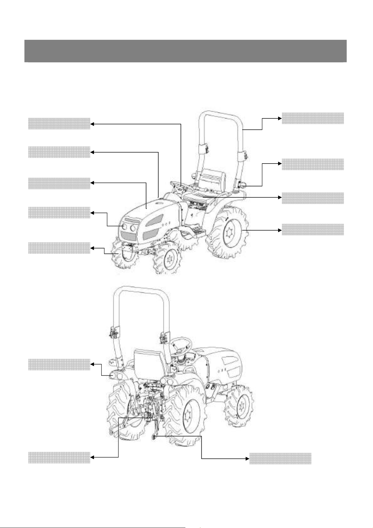
<1> OVERVIEW
GENERAL
Steering Wheel
Fuel Tank
Hood
Head Lamp
Front Tire
ROPS
Direction Lamp
Seat
Rear Tire
Combination Lamp
Drawbar
Lower Link
KUKJE MACHINERY CO., LTD.
3
2. OVERVIEW OF THE TRACTOR
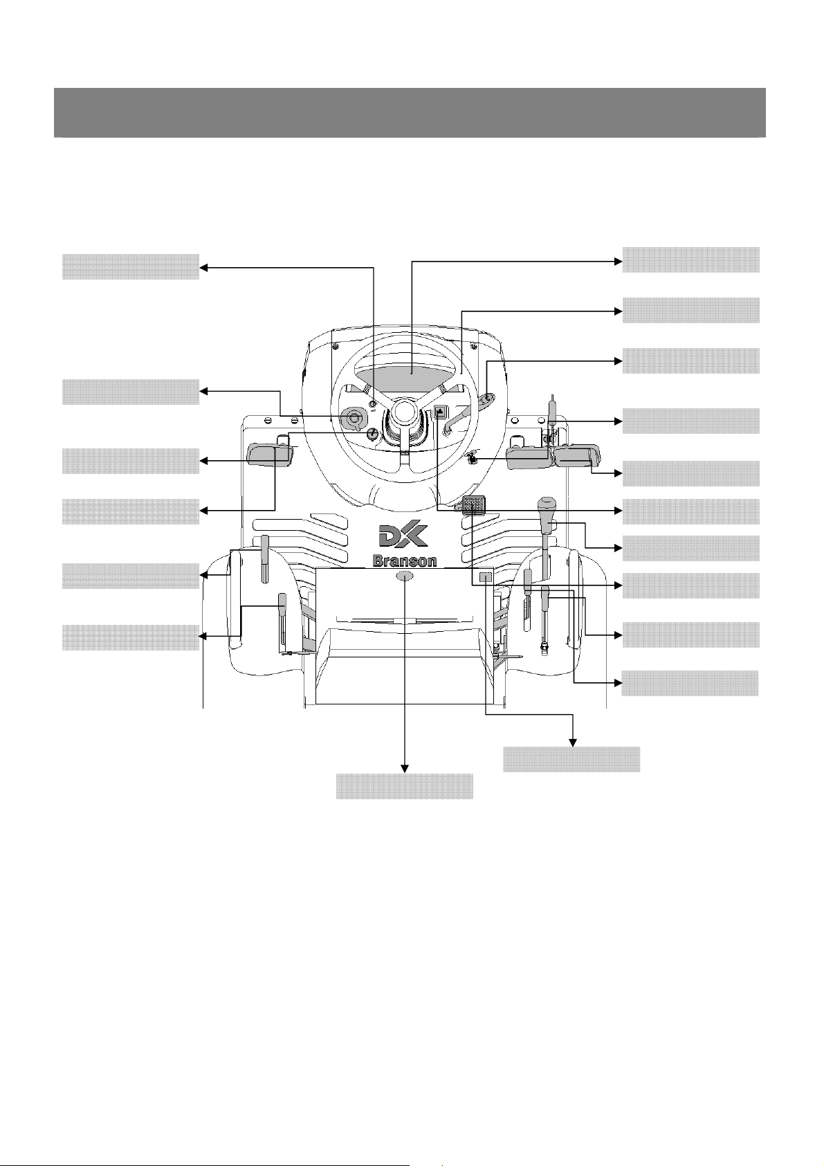
<2> OPERATION PART
1) Manual transmission
GENERAL
Emergency Stop S/W
Combination S/W
Side Lamp S/W
Clutch Pedal
Range Shift Lever
PTO Shift Lever
Instrument Panel
Steering Wheel
Accelerator Lever
Key Switch
Brake Pedal
Emergency Lamp S/W
Main Shift Lever
Accelerator Pedal
Position Lever
MFWD Lever
Slow Return Valve
Differential Lock Pedal
KUKJE MACHINERY CO., LTD.
4
2. OVERVIEW OF THE TRACTOR
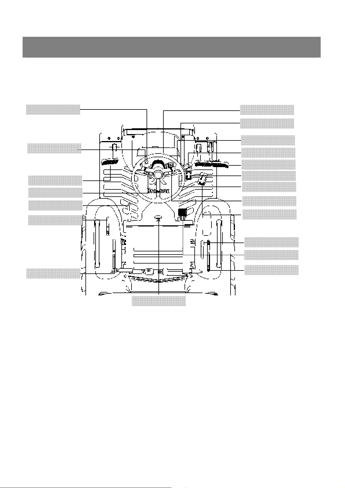
2) HST transmission
GENERAL
Emergency Stop S/W
Combination S/W
Clutch Pedal
Side Lamp S/W
Parking Lever
Range Shift Lever
PTO Shift Lever
Instrument Panel
Cruise S/W
Steering Wheel
Accelerator Lever
Brake Pedal
Forward Pedal
Key Switch
Emergency Lamp S/W
Backward Pedal
MFWD Lever
Differential Lock Pedal
Position Lever
Slow Return Valve
KUKJE MACHINERY CO., LTD.
5
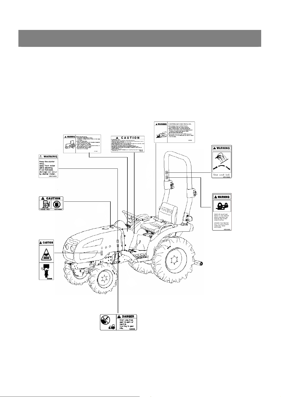
3. LOCATION OF SAFETY DECALS
LOCATION OF SAFETY DECALS
Safety decals are provided to ensure safe operation.
Keep the safety decals clean at all times and protect them from damage.
In case of loss or damage, replace with a new decal.
12. TZE5170000B4
GENERAL
6. NTE5270000A4
4.TZE4190000B4
10. TA00016518A 11.TA00016517A
9. NTE5150000C4
8. NTE5210000C4
5. TZE5130000B4
KUKJE MACHINERY CO., LTD.
7. TZE5110000B4
6
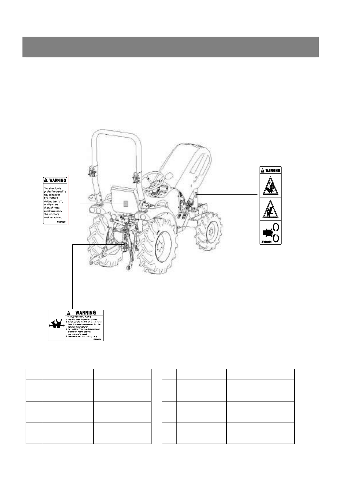
3. LOCATION OF SAFETY DECALS
LOCATION OF SAFETY DECALS
Safety decals are provided to ensure safe operation.
Keep the safety decals clean at all times and protect them from damage.
In case of loss or damage, replace with a new decal.
3. NTE6220000C4
GENERAL
1. TZE5180000B4
2. TZE4300000B4
No Part code Part description No Part code Part description
LABEL, FAN
1 TZE5180000B4
2 TZE4300000B4 LABEL, PTO CAUTION 8 NTE5210000C4 LABEL, PTO
3 NTE5220000C4 LABEL, SAFETY 9 NTE5150000C4 LABEL, DRAWBAR
4 TZE4190000B4
KUKJE MACHINERY CO., LTD.
WARNING 7 TZE5110000B4 LABEL, START CAUTION
LABEL, FILLER
CAUTION
10 TA00016518A LABEL, SAFETY
7
5 TZE5130000B4 LABEL, MUFFLER 11 TA0016517A LABEL, SAFETY
LABEL, START
GENERAL
6 NTE5270000A4
CAUTION 12 TZE5170000B4 LABEL, ROPS WARNING
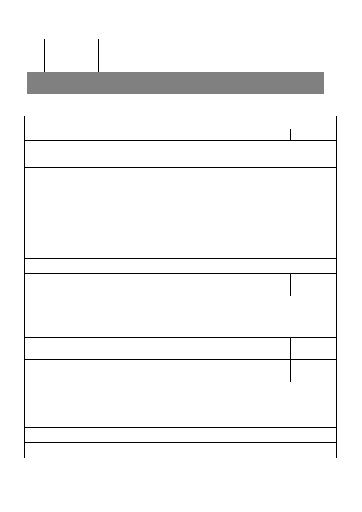
4. SPECIFICATIONS
<1> SPECIFICATION
Items Unit
Drive System 4 Wheel Drive
Main Dimensions
Overall Length in 106 (2692mm)
Overall Width in 44.3 (1124mm)
Overall Height in 87.2 (2216mm)
Wheel Base in 59.1 (1502mm)
Front Tread in 33.6 (853mm)
Manual transmission HST transmission
2100 2400 2800 2400h 2800h
Rear Tread in 34.6 (880mm)
Ground Clearance in 12.4 (315mm)
Weight lbs.
1785
(810kg)
Engine Vertical 4 cycle. Water cooled, Diesel
Model
Combustion System Swirl Chamber
Aspiration N/A
Engine Horsepower
HP 20.5 24.0 28.0 24.0 28.0
(2600 rpm)
No. of Cylinders 3
Bore x Stroke mm 74 X 82 78 X 82 78 X 82 78 X 82
Displacement cc 1058 1175 1175 1175
1805
(819kg)
1807
(820kg)
Turb o
Charger
1805
(819kg)
N/A
1807
(820kg)
Turb o
Charger
Compression Ratio 21.5:1 21:1 21:1
Fuel Consumption gal/hp.hr 0.067 (210 g/hp.hr)
KUKJE MACHINERY CO., LTD.
8

GENERAL
Type of Air Cleaner Dry, element
Fuel Tank Capacity gal 6.08 (23L)
4. SPECIFICATION
Manual transmission HST transmission
Items Unit
2100 2400 2800 2400h 2800h
Battery Volt 12
Steering Hydrostatic
Clutch Dry, single stage
Brake Wet disc
Transmission
Gear Shifting
6F x 2R
(F x R)
Tires (Agricultural) Turf and Industrial tires Available
Front 6 - 12
Rear 9.5 - 16
Rear PTO 6 spline shaft
Type Live
Speed 540 rpm, 960 rpm, 2500rpm(mid) @2600 engine rpm
MID PTO 14 spline shaft
Type Live
Speed 2500 rpm @ 2600 engine rpm
Hydraulic System Control / Position
Hydrostatic, high low gear shift
3 point hitch Category I
Lift capacity at lift
point
Pump Capacity gal/min 7.7 (29.0L/min)
lbs 1433 (650kg)
KUKJE MACHINERY CO., LTD.
9
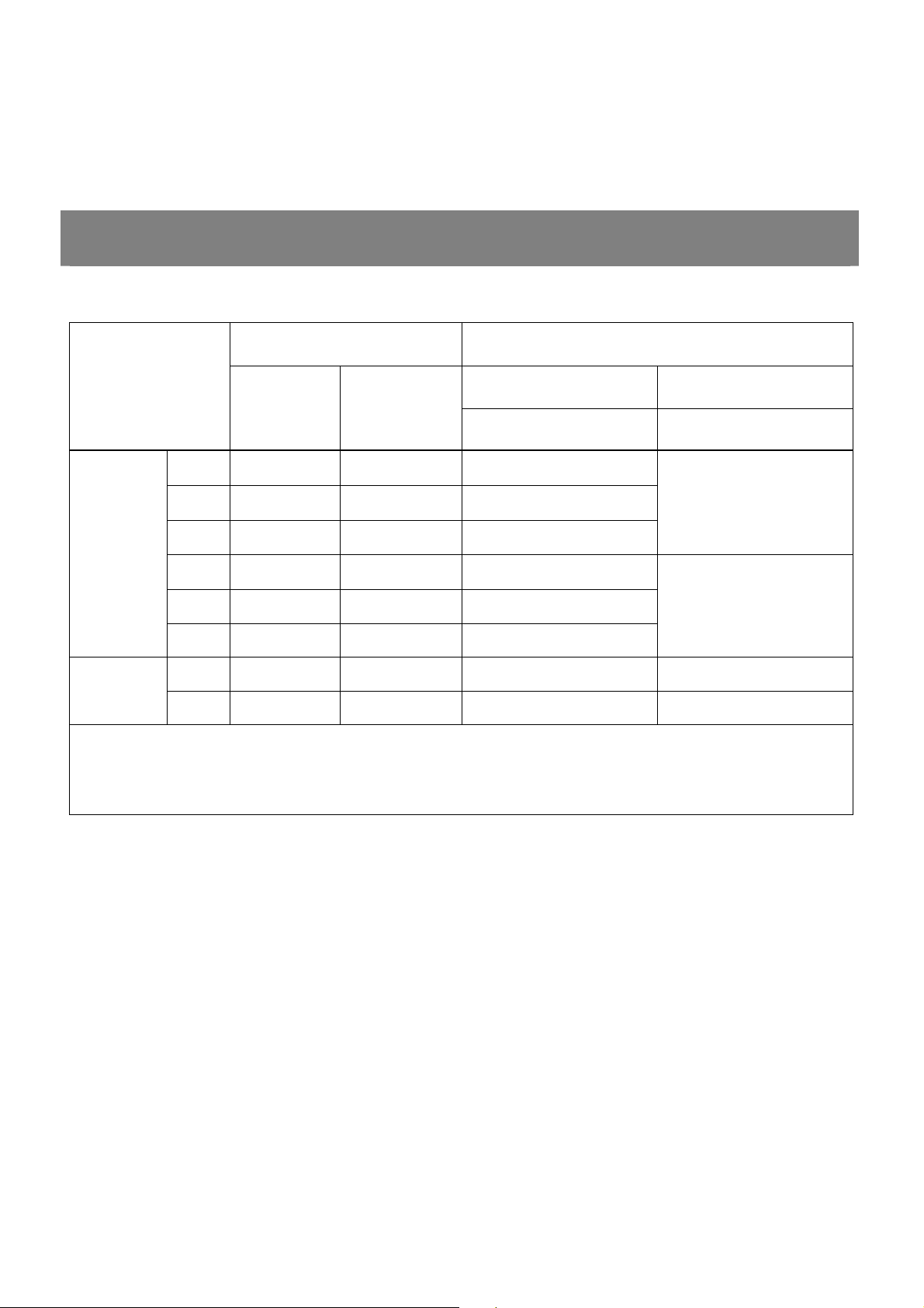
4. SPECIFICATIONS
<2> TRAVELING SPEED
GENERAL
SHIFTING MODEL
LEVEL
MAIN RANGE
1 1 L 0.7(1.1Km/h)
2 2 L 1.1(1.8Km/h)
3 3 L 2.1(3.3Km/h)
Forward
4 1 H 2.7(4.4Km/h)
5 2 H 4.8(7.8Km/h)
6 3 H 8.8(14.1Km/h)
1 R L 0.8(1.3Km/h) 2.3(3.7Km/h)
Reverse
2 R H 3.4(5.5Km/h) 5.8(9.3Km/h)
◎ Rated Engine rpm: 2600 rpm
Tire: agri 9.5-16 (423mm)
※ This specification will be changed without prior notice for improvement of quality
Manual transmission HST transmission
2100, 2400, 2800 2400h,2800h
3.9(6.2Km/h)
9.6(15.5Km/h)
※ Theory speeds figured by rated engine rpm (mile/hr)
KUKJE MACHINERY CO., LTD.
10
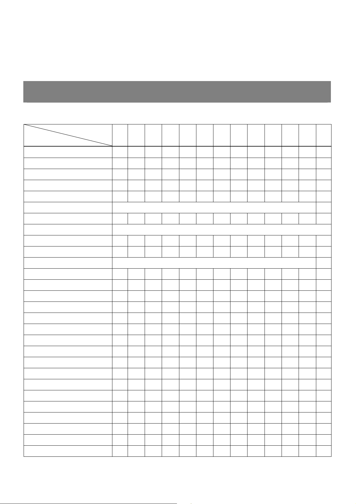
5. PERIODIC MAINTENANCE SCHEDULE
< SCHEDULE >
GENERAL
Running hours
Check items
Engine oil R R R R R R R
Transmission fluid R ○ ○ ○ ○ R ○ ○ ○ ○ ○ R
Front axle fluid R ○ ○ ○ ○ R ○ ○ ○ ○ ○ R
Engine oil filter R R R
Transmission fluid filter R R R
Radiator cleaning At the time the coolant is replaced
Fuel oil filter and element ○ ○ R ○ ○ R
Coolant Check before every use (Replace every year)
Air cleaner element ○ ○ ○ ○ ○ ○ ○ ○ ○ R ○ ○
Fan and radiator cleaning ○ ○ ○ ○ ○ ○ ○ ○ ○ ○ ○ ○
Battery solution Replace every two years
Battery (specific gravity) ○ ○ ○ ○ ○ ○
Fuel pipe and connection ○ ○ ○ ○ ○ ○ ○ ○ ○ ○ ○ ○
Steering wheel hose ○ ○ ○ ○ ○ ○ ○ ○ ○ ○ ○ ○
50 100 150 200 250 300 350 400 450 500 550 600
Radiator hose
Hydraulic fluid hose
Fuel hose, electric cables
Electric cables ○ ○ ○ ○ ○ ○ ○ ○ ○ ○ ○ ○
Greasing ○ ○ ○ ○ ○ ○ ○ ○ ○ ○ ○ ○
Tightening handles ○ ○ ○ ○ ○ ○
Tightening bolts ○ ○ ○ ○ ○ ○ ○
Cooling fan belt ○ ○ ○ ○ ○ ○ ○
Engine breed pipe ○ ○ ○ ○ ○ ○ ○
Engine crankcase cleaning ○ ○
Intake/Exhaust gas valves ○
Fuel injection valve ○
Generator motor ○ ○ ○ ○
Hydraulic system ○ ○ ○ ○
KUKJE MACHINERY CO., LTD.
11
GENERAL
※ Inspection should be done every 50 hours. If the tractor is not used much, inspect every year.
※ Replace parts every two years regardless of running hours.
※ Replace the steering wheel hose every two years.
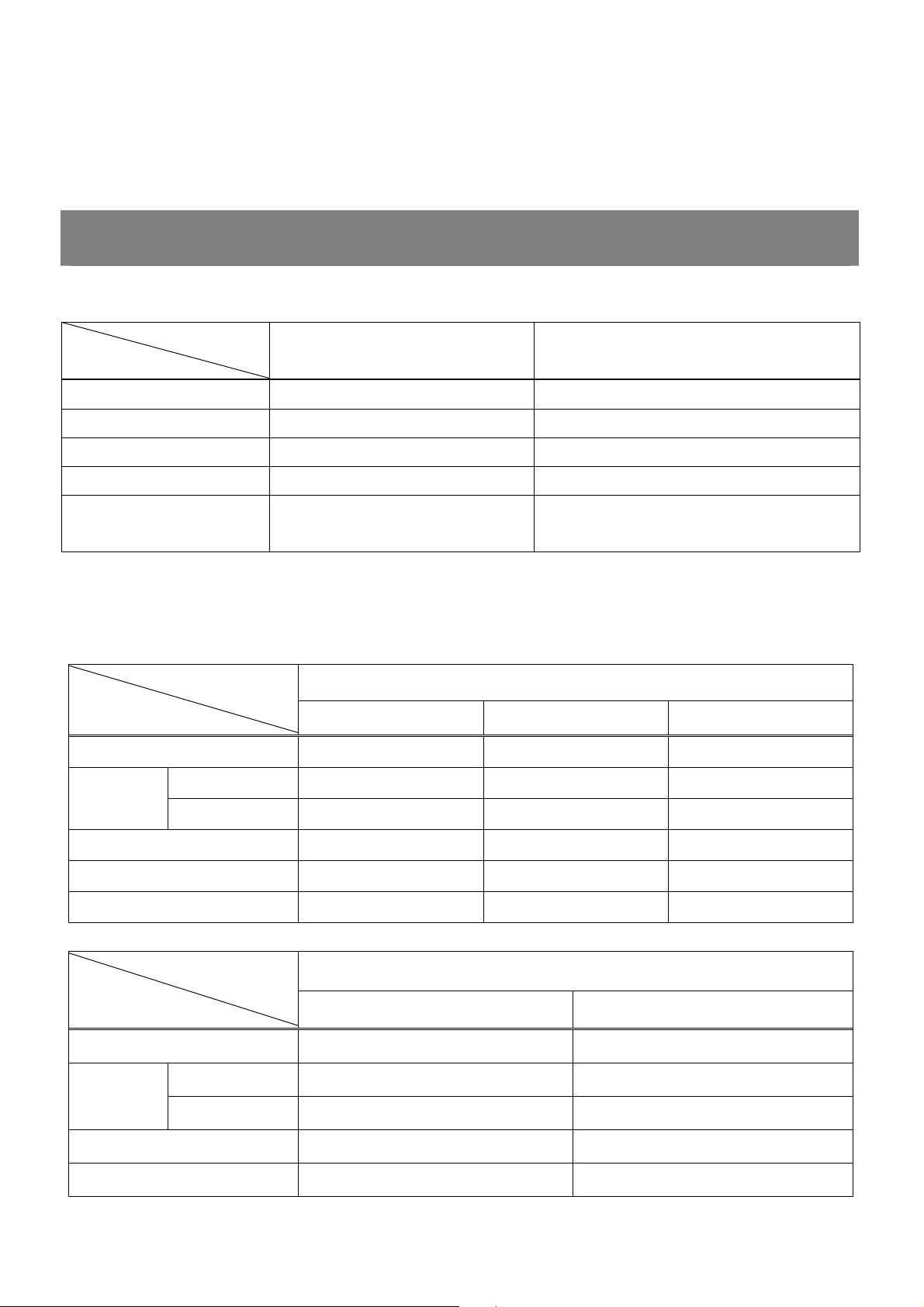
6. OIL, GREASE, ANTI-FREEZE, FUEL AND COOLANT CHART
<1> OIL, GREASE AND ANTI-FREEZE
Type
Item
Fuel Diesel(KS # 2) Summer: S,Winter:W
Engine oil SAE 10W-40 CG Above
Grease NO.2 of KSM2130 Multi purpose
Anti - Freeze International genuine product No.2 of KSM 2142,permanent type
Transmission, Steering,
Branson origin oil
Front axle fluid
Note) Use winter diesel when temperature is below 50’F.
Type Remarks
<2> FUEL, OIL AND COOLANT
Model
Type
Fuel 6.08 gal (23L) 6.08 gal (23L) 6.08 gal (23L)
Radiator 1.00 gal (3.8L) 1.00 gal (3.8L) 1.00 gal (3.8L)
Coolant
Sub tank 0.21 gal (0.8L) 0.21 gal (0.8L) 0.21 gal (0.8L)
2100 2400 2800
-Texaco TDH oil, 1893
-Chevron Tractor HYD Fluid
Manual Transmission
Engine oil 0.79 gal (3L) 0.79 gal (3L) 0.79 gal (3L)
Transmission oil 3.43 gal (13L) 3.43 gal (13L) 3.43 gal (13L)
Front axle oil 0.79 gal (3.0L) 0.79 gal (3.0L) 0.79 gal (3.0L)
Model
Type
Fuel 6.08 gal (23L) 6.08 gal (23L)
Radiator 1.00 gal (3.8L) 1.00 gal (3.8L)
Coolant
Sub tank 0.21 gal (0.8L) 0.21 gal (0.8L)
Engine oil 0.79 gal (3L) 0.79 gal (3L)
Transmission oil 3.96 gal (15L) 3.96 gal (15L)
KUKJE MACHINERY CO., LTD.
2400h 2800h
12
HST Transmission

GENERAL
Front axle oil 0.79 gal (3.0L) 0.79 gal (3.0L)
7. CHECK AND MAINTENANCE
▶ Be sure to check and service the tractor on a flat place with the engine shut off, the parking brake
on and chock the wheels.
<1> DAILY CHECK
To prevent trouble from occurring, it is important to know the condition of the tractor, Check the
following items before starting.
KUKJE MACHINERY CO., LTD.
13

GENERAL
< Checking >
▶ Check areas where previous trouble was experienced.
▶ Walk around the tractor.
1. Check the tire pressure, and check for wear and damage.
2. Check for oil and water leaks.
3. Check the engine oil level.
4. Check the transmission fluid level.
5. Check the coolant level.
6. Check the condition of seat belt and ROPS attaching hardware.
7. Check and clean the radiator screen and grill.
8. Check that the bolts and nuts of the tires are tight.
9. Check the number plate or SMV emblem for damage and clean, replace as necessary of equipped.
10. Care of danger, warning, and caution labels.
11. Clean around the exhaust manifold and the muffler of the engine.
▶ While sitting in the operator’s seat.
1. Check the HST pedal, brake pedal and clutch pedal.
2. Check the parking brake.
3. Check the steering wheel.
▶ Turning the key switch.
1. Check the performance of the instrument panel lights.
2. Check the head lights, tail lights and hazard lights. Clean if necessary.
3. Check the performance of the meters and gauges.
▶ Starting the engine.
1. Check to see that the lights on the easy checker go off.
2. Check the color of the exhaust gas.
3. Check the brakes for proper operation.
7. DISASSEMBLING AND SERVICING
<2> CHECK POINTS OF INITIAL 50 HOURS
KUKJE MACHINERY CO., LTD.
14
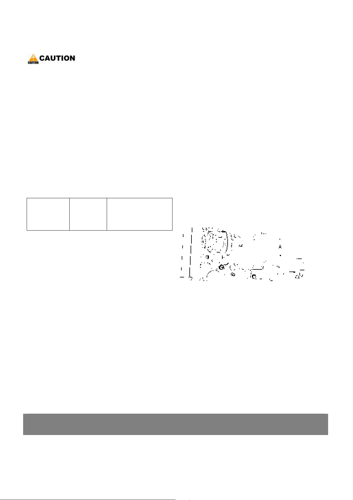
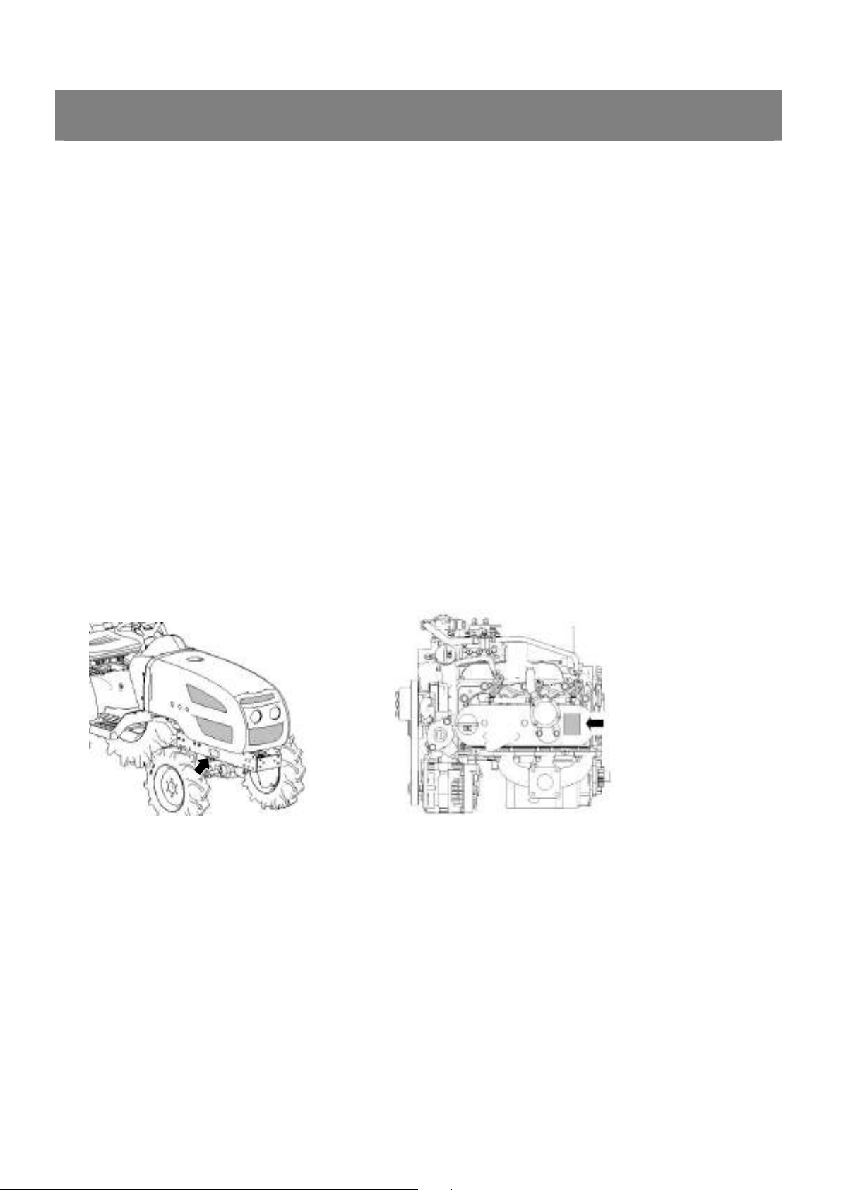
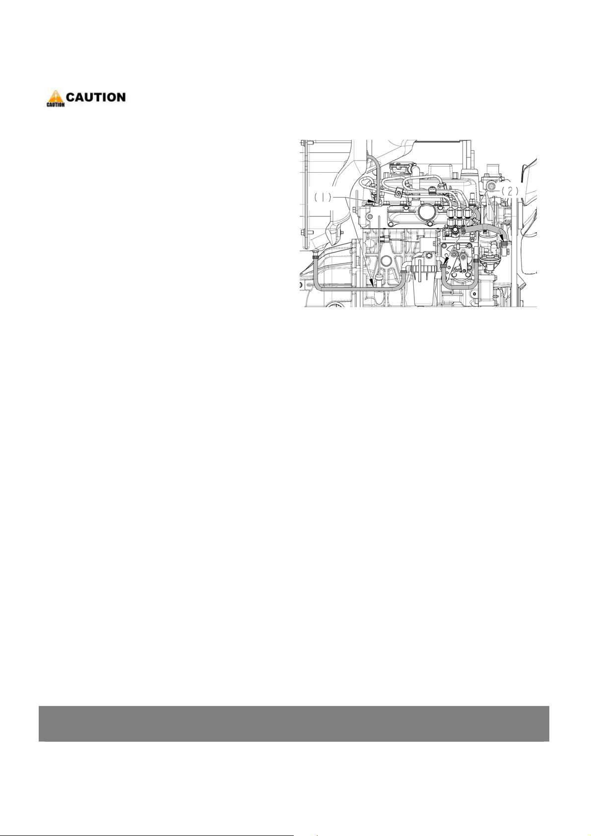
< Changing engine oil >
▶ Be sure to stop the engine.
▶ Allow engine to cool down sufficiently,
oil can be hot and can burn.
1. Place an oil pan underneath the engine.
2. To drain the used oil, remove the drain plug(1) at
the bottom of the engine and drain the oil
completely.
3. Screw in the drain plug(1).
4. Fill with the new oil up to the upper notch on
the dipstick.
◈ Important
¾ Never mix two different types of oil.
GENERAL
Engine oil
2100
2400(h)
capacity
2800(h)
3.0 L
3.17 U.S.qts
0.79 gal
*. PART NAME
1) Drain plug 2) Oil inlet
3) Dipstick
(3)
7. DISASSEMBLING AND SERVICING
KUKJE MACHINERY CO., LTD.
15

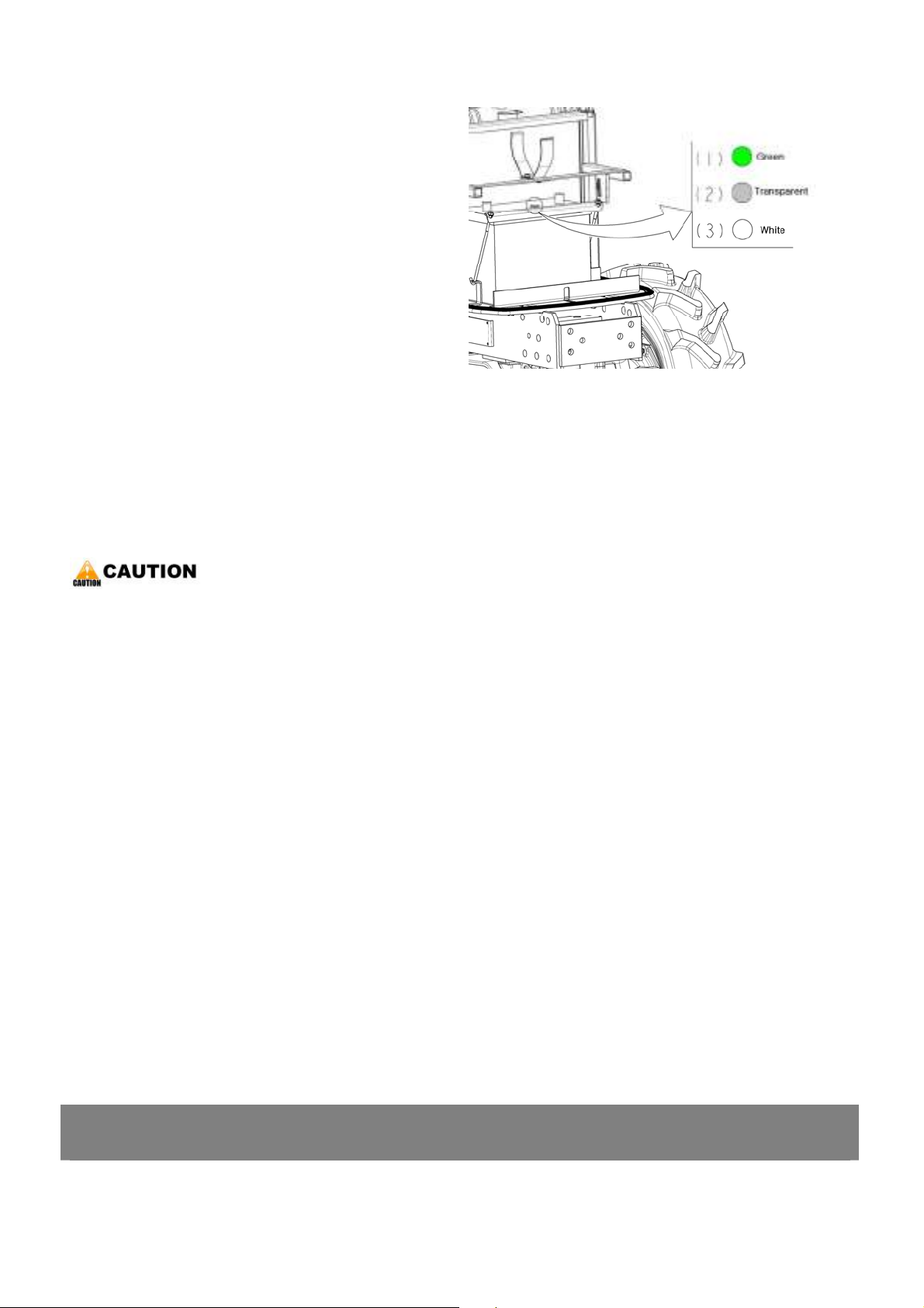
< Replacing engine oil filter cartridge >
▶ Be sure to stop the engine before changing oil
filter cartridge.
1. Remove the oil filter cartridge with the filter
wrench.
2. Apply a slight coat of oil onto the cartridge
GENERAL
gasket.
3. To install the new cartridge, screw it in by hand.
Over tightening may cause deformation of
rubber gasket.
4. After the new cartridge has been replaced, the
engine oil normally decrease a little. Thus see
that the engine oil does not leak through the
seal and be sure to read the oil level on the
dipstick. Then, replenish the engine oil up to the
specified level.
◈ Important
¾ To prevent serious damage to the engine,
replacement element must be highly efficient.
Use only a Branson genuine filter.
*. PART NAME
1) Engine oil filter
7. DISASSEMBLING AND SERVICING
KUKJE MACHINERY CO., LTD.
16
< Changing transmission fluid >
▶ Be sure to stop the engine before checking and
changing the transmission fluid.
1. Place an oil pan under the tractor.
2. Remove the drain plugs(1) at the bottom of the
rear axle cases, transmission case and front
transmission case.
3. Drain the transmission fluid.
4. After draining, screw in the four drain plugs.
5. Fill new oil from filling port after removing the
filling plug(2), up to the upper notch on the
dipstick.
6. After running the engine for a few minuets, stop
it and check the oil level again, if low, add oil to
proper level.
(1)
(1)
GENERAL
◈ Important
¾ Use only multi-grade transmission oil. Use of
other oils may damage the transmission of
hydraulic system.
¾ Never work the tractor immediately after
changing the transmission oil. Keep the engine
at medium speed for a few minutes to prevents
damage to the transmission.
2100
2400
Transmission
2800
fluid capacity
2400h
2800h
Front case 3L (0.79gal)
Rear case 13L (3.43gal)
Front case 3L (0.79gal)
Rear case 15L (3.96gal)
*. PART NAME
1) Drain plug 2) Filling plug
(1)
(3)
3) Dipstick
7. DISASSEMBLING AND SERVICING
KUKJE MACHINERY CO., LTD.
17
< Replacing hydraulic oil filter cartridge >
▶ Be sure to stop the engine before changing the
oil filters.
1. Drain the transmission fluid.
2. Remove the oil filter cartridge by using a filter
wrench.
3. Apply a slight coat of oil onto the cartridge
gasket.
4. To install the new cartridge, screw it in by hand.
Over tightening may cause deformation of
rubber gasket.
5. After the new cartridge has been replaced, the
transmission fluid level will normally decrease
slightly. Make sure that the transmission fluid
GENERAL
(1)
does not leak through the seal. Check the fluid
level.
◈ Important
¾ To prevent serious damage to the hydraulic
system. Use only a genuine Branson filter.
< Cleaning transmission oil strainer (HST) >
1. Clean the strainer with nonflammable solvent.
▶ NOTE
1) When changing the transmission fluid,
disassemble and rinse the strainer with
nonflammable solvent to completely clean off
filings. When reassembling, be careful not to
damage the parts.
2) Since the fine filings in the oil could impair the
component parts of the hydraulic system which
is precision built to withstand high pressure, the
suction line end is provided with an oil strainer.
(2)
*. PART NAME
1) Hydraulic oil filter (HST) 2) Hydraulic oil filter
3) Please do the replacing, of the oil filter cartridge
and the cleaning oil strainer at the same time.
And when replacing, reinstall the oil strainer first.
7. DISASSEMBLING AND SERVICING
KUKJE MACHINERY CO., LTD.
18
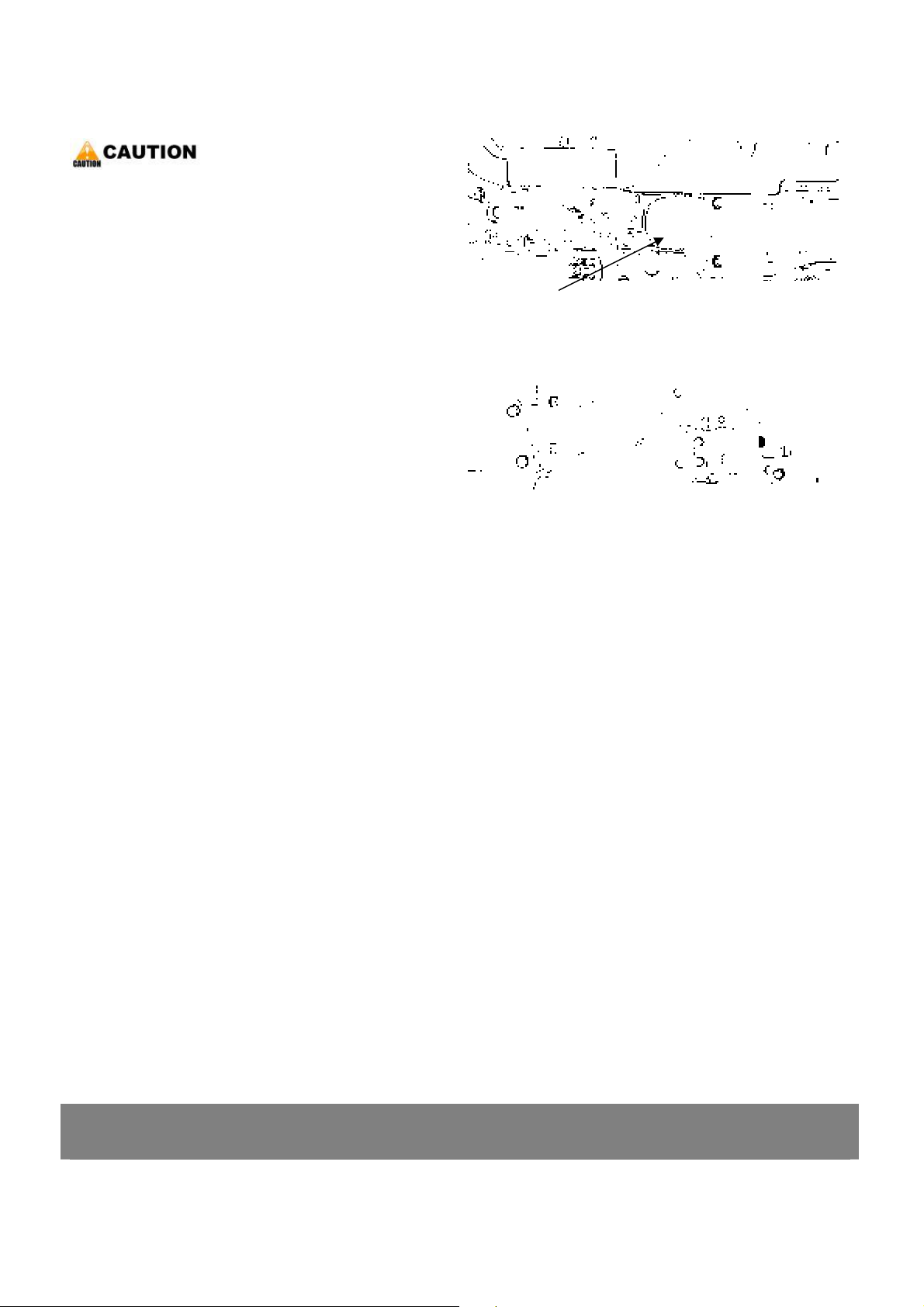
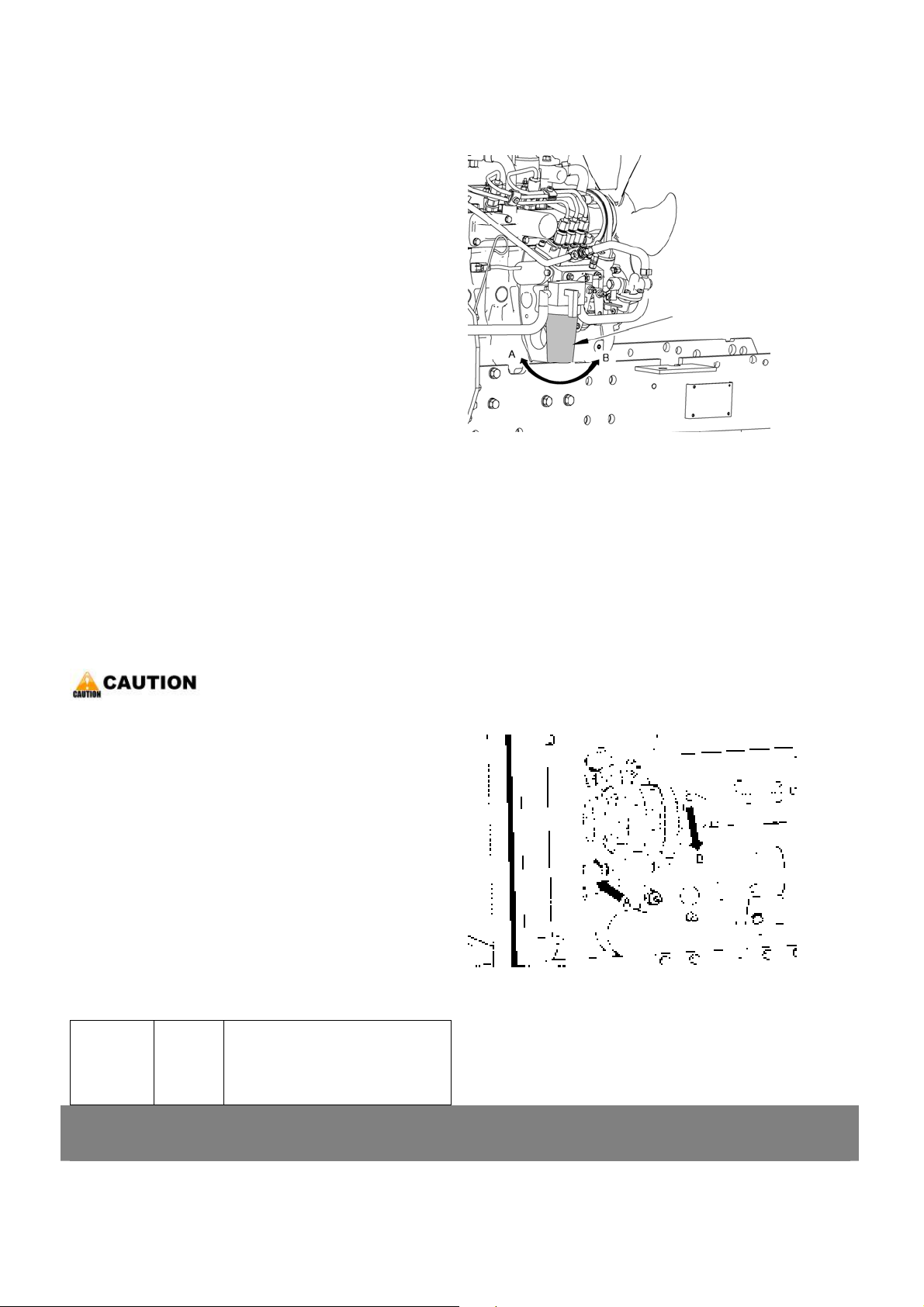
< Checking clutch pedal free travel >
▶ When checking, park the tractor on flat ground,
apply the parking brake, stop the engine and
remove the key.
1. Slightly depress the clutch pedal and measure
stroke “A” at top of stopper bolt(1).
2. If the measurement is not within the factory
specifications, loosen the lock nut and adjust the
clutch pedal rod(2) length.
3. After adjusting it, measure total stroke “B”
between stopper bolt(1) and clutch housing(4).
GENERAL
4. If the measurement is not within the factory
specifications, adjust it with the clutch pedal
stopper bolt(1).
5. And at the same time, adjust the clearance “C”
between safety switch(5) and clutch rod(6).
▶ NOTE
1) After adjustment, secure the stopper bolt with
the lock nut(3).
Clutch pedal free travel on
stopper bolt stroke “A”
Reference :
Clutch pedal free travel “L”
on top of clutch pedal.
Clearance “B”
Factor y
spec.
Factor y
spec.
7.0 to 9.0 mm
0.28 to 0.35 in.
25.0 to 35.0 mm
0.98 to 1.38 in.
1.5 to 2.0 mm
0.06 to 0.08 in.
L
*. PART NAME
1) Stopper bolt 2) Clutch pedal rod
3) Lock nut for stopper bolt 4) Clutch housing
5) Satety switch 6) Clutch rod
7. DISASSEMBLING AND SERVICING
<3> CHECK POINTS OF EVERY 50 HOURS
KUKJE MACHINERY CO., LTD.
19
GENERAL
< Checking engine start system >
▶ Do not allow anyone near the tractor while
testing.
▶ If the tractor does not pass the test do not
operate the tractor.
▷ Preparation before testing
1. Sit on operator’s seat.
2. Set the parking brake and stop the engine.
3. HST type
-. Shift the range gear shift lever to “Neutral”
position.
-. Place the speed control pedal in “Neutral”
position.
Manual transmission type
-. Shift the main gear shift lever in “Neutral”
position.
4. Shift the PTO gear shift lever to “Neutral”
position.
5. Fully depress the clutch pedal.
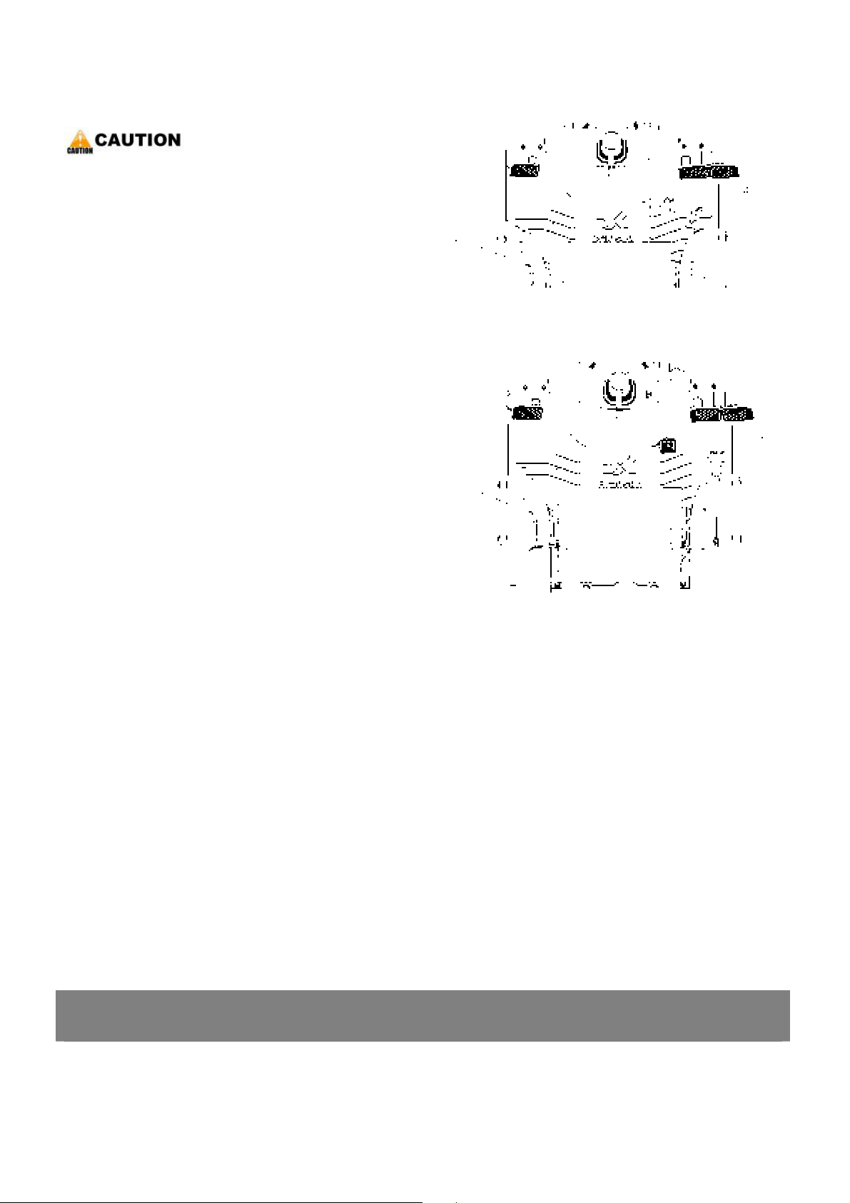
▷ Test 1 : Safety switch for clutch pedal
1. Place the speed control pedal in “Neutral”
position for a HST type or shift the main gear
shift lever for a Manual transmission type to
“Neutral” position.
2. Release the clutch pedal.
3. Turn the key to “Start” position.
4. The engine must not crank.
*. PART NAME
1) Clutch pedal 2) Range shift
3) PTO gear shift 4) Speed control pedal
5) Main gear shift
7. DISASSEMBLING AND SERVICING
KUKJE MACHINERY CO., LTD.
20

▷ Test 2 : Safety switch for HST of main gear
1. Fully depress the clutch pedal.
2. Depress the speed control pedal HST type or
shift the main gear shift lever Manual
GENERAL
transmission type to “Desired” position.
3. Turn the key to “Start” position.
4. The engine must not crank.
▷ Test 3 : Safety switch for PTO
1. Fully depress the clutch pedal.
2. Place the speed control pedal in “Neutral”
position HST type or shift the main gear shift
lever Manual transmission type to “Neutral”
position.
3. Shift the PTO gear shift lever to “On”(Engaged)
position.
4. Turn the key to “Start” position.
5. The engine must mot crank.
▷ Test 4 : Seat switch
1. Sit on operator’s seat.
2. Start the engine.
3. Fully depress the clutch pedal.
4. Shift the PTO gear shift lever to “On”(Engaged)
(1)
(2)
(4)
(3)
position.
5. Stand up. (Do not get off the machine.)
6. The engine must shut off after approximately 1
second.
7. If it does not stop, consult your local Branson
Dealer for this service.
▶ NOTE
1) If the engine cranks during nay of these tests,
adjust or replace the required safety switch.
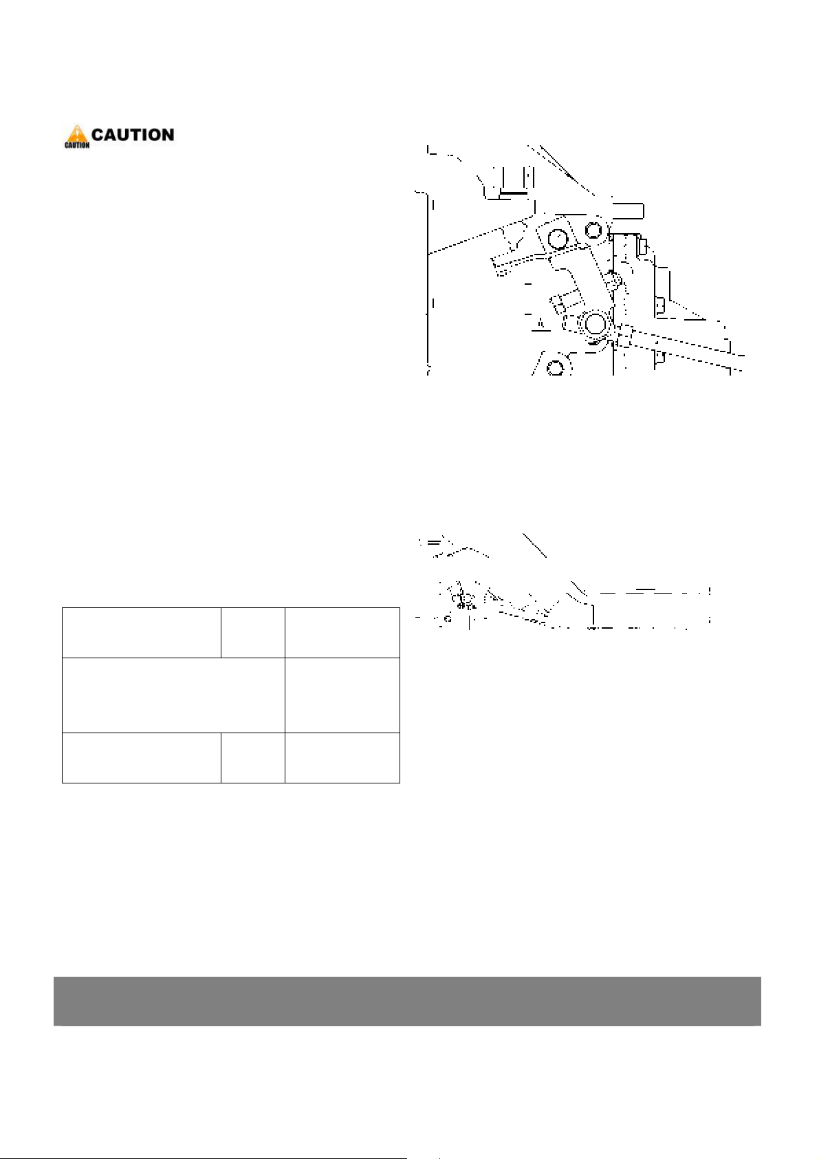
< Greasing >
1. Apply the grease to the following position as
figures.
7. DISASSEMBLING AND SERVICING
(5)
*. PART NAME
1) Grease fitting(HST pedal) 2) Battery terminals
3) Grease fitting (Lifting rod RH)
4) Grease fitting (Top link)
5) Front axle tie rod
KUKJE MACHINERY CO., LTD.
21
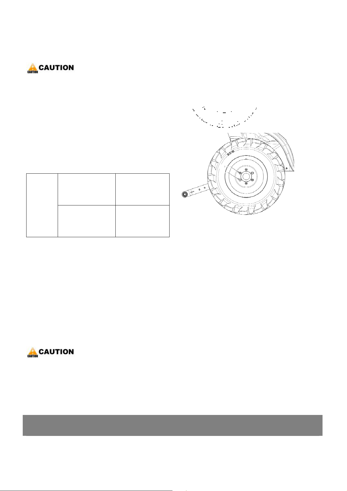
< Checking wheel mounting screws and nuts
tightening torque >
▶ Never operate tractor with a loose rim, wheel,
or axle.
▶ Any time bolts and nuts are loosened,
retighten to specified torque.
GENERAL
▶ Check all bolts and nuts frequently
and keep them tight.
1. Check wheel bolts and nuts regularly especially
when new. If there are loosened, tighten as
follows.
Front wheel mounting
bolt
Tightening
torque
Rear wheel mounting
Nut / bolt
77 to 90 Nm
7.9 to 9.2 kgfm
57.2 to 66.5 ft-lbs
108 to 125 Nm
11.0 to 12.8 kgfm
80 to 93 ft-lbs
<4> CHECK POINTS OF EVERY 100 HOURS
< Changing engine oil >
(2)
(3)
*. PART NAME
1) Front wheel mounting bolt
2) Rear wheel mounting bolt
3) Rear wheel mounting nut
-. Reference the page. 14.
< Checking clutch pedal free travel >
-. Reference the page. 18.
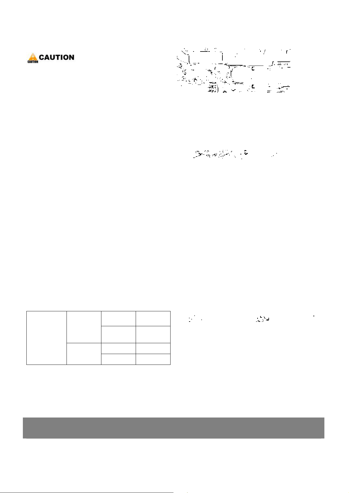
< Checking battery condition >
▶ Never remove the vent plugs
while the engine is running.
7. DISASSEMBLING AND SERVICING
KUKJE MACHINERY CO., LTD.
22
▶ Keep electrolyte away from eyes, hands and
clothes. If you are spattered with it, wash it
away completely with water immediately
and get medical attention.
▶ Wear eye protection and rubber gloves
when working around battery.
1. Mishandling the battery shortens the service life
and adds to maintenance costs.
2. The original battery is a maintenance free type,
but stills needs some servicing. If the battery is
GENERAL
weak, the engine is difficult to start and the
lights become dim. It is important check the
battery periodically.
< Battery charging >
▶ When the battery is being activated, hydrogen
and oxygen gases in the battery are extremely
explosive. Keep open sparks and flames away
from the battery at all times, especially when
charging the battery.
▶ When charging battery, remove battery vent
plugs.
▶ When disconnecting the cable from the battery,
start with the negative terminal first. When
*. PART NAME
1) Good 2) Charge
3) Change
connecting the cable to the battery, start with the
positive terminal first.
▶ Never check battery charge by placing a metal
object across the posts. Use a voltmeter or
hydrometer.
7. DISASSEMBLING AND SERVICING
KUKJE MACHINERY CO., LTD.
23

GENERAL
1. Make sure each electrolyte level is to the bottom
of vent wells, if necessary add distilled water in a
well-ventilated area.
2. The water in the electrolyte evaporates during
recharging. Liquid shortage damages the battery.
Excessive liquid spills over and damages the
tractor body.
3. To slow charge the battery, connect the battery
positive terminal to the charger positive terminal
and the negative to the negative, then recharge
in the standard fashion.
4. A boost charge is only for emergencies. It will
partially charges the battery at a high rate and in
a short time. When using a boost-charged
battery, it is necessary to recharge the battery as
early as possible. Failure to do this will shorten
the battery’s service life.
5. When the specific gravity of electrolyte become
between 1.27 and 1.29 charge has completed.
6. When exchanging an old battery for a new one,
use battery of equal specification.
◆ Direction for storage
1. When storing the tractor for long periods of
time, remove the battery from tractor, adjust the
electrolyte to the proper level and store in a dry
place out of direct sunlight.
2. The battery self-discharges while it is stored.
Recharge it once every three months in hot
seasons and once every six months in cold
seasons.
Battery
Type
BX50S 12 40 90 480 4.5
Vol t s
(V)
Capacity
at 5H.R
(A.H.)
Reserve
Capacity
(min.)
Cold
Cranking
Amps
Normal
Charging
Rate(A)
7. DISASSEMBLING AND SERVICING
KUKJE MACHINERY CO., LTD.
24
GENERAL
< Cleaning air cleaner element >
1. Remove the air cleaner cover(1) and primary
element(2).
2. Cleaning the primary element :
▷ When dry dust adheres to the element, blow
compressed air from the inside turning the
element. Pressure of compressed air must be
under 205kPa (2.1 kgf/㎠, 30 psi).
▷ When carbon or oil adheres to the element,
soak the element in detergent for 15 minutes
then wash it several times in water, rinse with
clean water and dry it naturally. After the
element is fully dried, inspect inside of the
element with a light and check if it is damaged
or not.
3. When to replace the air cleaner primary
element(2) : Once a year or after every six times
*. PART NAME
1) Cover 2) Primary element
3) Evacuator valve
of cleaning, whichever comes first.
◈ Important
¾ The air cleaner uses a dry element, never apply
oil.
¾ Do not run the engine with the filter element
removed.
¾ Be sure to refit the dust cup with the arrow↑(on
the rear of cup) upright. If the dust cup is
improperly fitted, evacuator valve will not
function and dust will adhere to the element.
¾ Do not touch the secondary element except in
cases where replacing is required.
◆ Evacuator valve
Open the evacuator valve once a week under
ordinary conditions or daily when used in a dusty
place to get rid of large particles of dust and dirt.
7. DISASSEMBLING AND SERVICING
KUKJE MACHINERY CO., LTD.
25
GENERAL
< Cleaning fuel filter >
This job should not be done in the field, but in a
clean place.
1. Loosen and remove the fuel filter bowl(2), and
rinse the inside with kerosene.
2. Take out the filter element(4) and dip it in the
kerosene to rinse.
3. After cleaning, reassemble the fuel filter, keeping
out dust and dirt.
4. Bleed the fuel system.
▶ NOTE
1) When the fuel filter bowl has been removed, fuel
stops flowing from the fuel tank. If the fuel tank
is almost full, however, the fuel will flow back
from the fuel return pipe to the fuel filter. Before
checking the above, mark sure the fuel tank is
less than half-full.
(2)
*. PART NAME
1) Filter bracket
2) Fuel filter bowl
3) O-ring
4) Filter element
5) O-ring
< Checking fan belt tension >
▶ Be sure to stop engine before checking belt
tension.
1. Stop the engine and remove the key.
2. Apply moderate thumb pressure to the belt
between pulleys.
3. If the tension is incorrect, loosen the alternator
mounting bolts and, using a lever placed
between the alternator and the engine block,
pull the alternator out until the deflection of the
belt falls within acceptable limits.
4. Replace fan belt if it is damaged.
Fan belt
tension
Factor y
spec.
A deflection of between 7 to 9mm
(0.28 to 0.34 in.) when the belt is
pressed in the middle of the span.
A) Loosen
B) Tighten
*. PART NAME
1) Adjusting screw 2) Tension bolt
A) Check the belt tension B) To tighten
7. DISASSEMBLING AND SERVICING
KUKJE MACHINERY CO., LTD.
26
< Adjusting brake pedal free travel >
▶ Stop the engine and chock the wheels before
checking the brake pedal.
▶ The difference between the right and left pedal
free travel must be less than 4.0 mm (0.16 in.).
1. Release the parking brake.
2. Slightly depress the brake pedals and measure
GENERAL
the free travel at the top of the pedal stroke.
3. If the measurement is not within the factory
specifications, loosen the lock nut and turn the
turnbuckle to adjust the brake rod length.
4. Retighten the lock nut securely.
5. Keep the free travel in the right and left brake
pedals equal.
Brake pedal
Factor y spec.
free travel (L)
▶ NOTE
30 to 40 mm
1.18 to 1.57 in.
1) After checking brake pedal free travel, be sure to
engage the parking brake lever fully and check
to see that the brake pedals are securely locked.
*. PART NAME
1) Brake pedal 2) Turnbuckle
3) Lock nut
L : Free travel
7. DISASSEMBLING AND SERVICING
KUKJE MACHINERY CO., LTD.
27
GENERAL
< Checking fuel line >
▶ Stop the engine when attempting the check and
change prescribed below.
▶ Remember to check the fuel line periodically.
The fuel line is subject to wear and aging, fuel
may leak out onto the running engine, causing
a fire.
1. Check to see that all line and hose clamps are
tight and not damaged.
2. If hoses and clamps are found worn or damaged,
replace or repair them at once.
3. The fuel line is made of rubber and ages
regardless of period of service. Replace the fuel
pipe together with the clamp every two years
and securely tighten.
4. However if the fuel pipe and clamp are found
*. PART NAME
1) Fuel hoses 2) Hose clamps
damaged or deteriorated earlier than two years,
then change or repair.
5. After the fuel line and clamp have been
changed, bleed the fuel system.
◈ Important
¾ When the fuel line is disconnected for change,
close both ends of the fuel line with a piece of
clean cloth of paper to prevent dust and dirt
from entering. Entrance of dust and dirt causes
malfunction of the fuel injection pump. In
addition, particular care must be taken not to
admit dust and dirt into the fuel pump.
7. DISASSEMBLING AND SERVICING
<5> CHECK POINTS OF EVERY 200 HOURS
KUKJE MACHINERY CO., LTD.
28
< Replacing engine oil filter cartridge >
-. Reference the page 15.
< Checking intake air line >
1. Check to see that hoses and hose clamps are
tight and not damaged.
2. If hoses and clamps are found worn or damaged,
replace or repair them at once.
< Checking radiator hose and hose clamp >
GENERAL
▶ Check to see if radiator hoses are properly fixed
every 200 hours of operation or six months,
whichever comes first.
1. If hose clamps are loose or water leaks, tighten
bands securely.
2. Replace hoses and tighten hose clamps securely,
if the radiator hoses are swollen, hardened or
cracked. Replace hoses and hose clamps every 2
years or earlier if checked and found that hoses
are swollen, hardened or cracked.
◆ Precaution at overheating
Take the following actions in the event the coolant
temperature is near or more than the boiling point,
which is called “Overheating”.
1. Stop the machine operation in a safe place and
keep the engine unloaded idling.
2. Don’t stop the engine suddenly, but stop it after
*. PART NAME
1) Hose 2) Hose clamps
*. PART NAME
1) Hose 2) Clamp
about 5 minutes of unloaded idling.
3. Keep yourself well away from the machine for
another 10 minutes or while the steam has
blown out.
4. Checking that there gets on danger such as
burn, get rid of the causes of overheating
according to the manual and start again the
engine.
7. DISASSEMBLING AND SERVICING
<6> CHECK POINTS OF EVERY 300 HOURS
KUKJE MACHINERY CO., LTD.
29

< Changing transmission fluid >
-. Reference the page 16.
< Cleaning transmission oil strainer >
-. Reference the page 17.
< Replace hydraulic oil filter cartridge >
-. Reference the page 17.
< Changing front axle case oil >
1. Place the oil pans underneath the front axle case.
2. Remove the both right and left hand side drain
plugs(2) and filling plug(1) to drain the oil.
3. After draining, reinstall the drain plugs(2).
4. Fill with new oil up to the upper notch on the
dipstick.
GENERAL
◈ Important
¾ After ten minutes, check the oil level again, add
oil to proper level.
¾ Use Branson genuine fluid.
Front axle case
2100
2400(h)
oil capacity
2800(h)
3.0 L
3.17 U.S.qts
0.79 gal
*. PART NAME
1) Filling plug with dipstick 2) Drain plug
A) Oil level is acceptable within this range
7. DISASSEMBLING AND SERVICING
<7> CHECK POINTS OF EVERY 400 HOURS
KUKJE MACHINERY CO., LTD.
30

< Front axle rocking force >
1. Jack up the front side of tractor.
2. Set a spring balance to the front axle flange.
3. Measure the front axle rocking force.
4. If the measurement is not within the factory
specifications, adjust by the adjusting screw(1).
5. Tighten the lock nut(2) firmly.
GENERAL
Front axle
Factor y spec.
rocking force
*. PART NAME
1) Adjusting screw 2) Lock nut
49.0 to 98.1 N
5.0 to 10.0 kgf
11.0 to 22.1 lbs
< Replace fuel filter element >
1. The fuel filter element should be replaced every
400 hours.
*. PART NAME
1) Filter bracket 2) Fuel filter bowl
3) O-ring 4) Filter element
5) O-ring
<8> CHECK POINTS OF EVERY 800 HOURS
< Checking valve clearance >
-. Reference the engine service manual.
<9> CHECK POINTS OF EVERY 1500 HOURS
< Checking fuel injection nozzle injection pressure >
-. Reference the engine service manual.
<10> CHECK POINTS OF EVERY 3000 HOURS
< Checking injection pump >
-. Reference the engine service manual.
<11> CHECK POINTS OF 1 YEAR
< Replace air cleaner primary element and secondary element >
-. Reference the page 24.
7. DISASSEMBLING AND SERVICING
<12> CHECK POINTS OF 2 YEARS
KUKJE MACHINERY CO., LTD.
31

GENERAL
< Replacing radiator hose (Water pipes) >
1. Replace the hoses and clamps.
-. Reference the page 28.
< Replacing fuel hose >
1. Replace the fuel hoses and clamps.
-. Reference the page 27.
< Replacing intake air line >
1. Replace the hoses and clamps, if necessary.
-. Reference the page 28.
< Flush cooling system and changing coolant >
▶ Do not remove the radiator cap when the engine
is hot. Then loosen cap slightly to the stop to
relieve any excess pressure before removing cap
completely.
1. Stop the engine and let cool down.
2. To drain the coolant, open the radiator drain
cock, and remove radiator cap. The radiator cap
must be removed to completely drain the
coolant.
3. After all coolant is drained, close the drain plug.
4. Fill with clean water and cooling system cleaner.
5. Follow directions of the cleaner instruction.
6. After flushing, fill with clean water and anti-
freeze until the coolant level is just below the
port.
7. Start and operate the engine for few minutes.
8. Stop the engine. Check coolant level and add
coolant if necessary.
9. Install the radiator cap securely.
*. PART NAME
1) Radiator cap 2) Recovery tank
3) Drain cock
7. DISASSEMBLING AND SERVICING
KUKJE MACHINERY CO., LTD.
32

GENERAL
◈ Important
¾ Do not start the engine without coolant.
¾ Use clean, fresh water and anti-freeze to fill the
radiator.
¾ When the anti-freeze is mixed with water, the
anti-freeze mixing ratio must be less than 50%.
¾ Securely tighten radiator cap. If the cap is loosen
or improperly fitted, water may leak out and the
engine could overheat.
Coolant
capacity(with
recover y tank)
2100
2400(h)
2800(h)
3.8 L
4.0 U.S.qts
1.0 gal
< Flush cooling system and changing coolant
(Continued) >
◆ Anti-freeze
If it freezes, cooling water can damage the
cylinders and radiator. When it may be necessary the
ambient temperature falls below 0℃(32℉) to remove
coolant water after operating or to add anti-freeze to
it.
1. There are two types of anti-freeze available; use
the permanent type for this engine.
2. Before adding anti-freeze for the first time, clean
the radiator interior by pouring fresh water and
draining it a few times.
3. The procedure for mixing the water and anti-
freeze differs according to the make of the anti-
freeze and the ambient temperature.
7. DISASSEMBLING AND SERVICING
KUKJE MACHINERY CO., LTD.
33

GENERAL
4. Mix the anti-freeze with water, and then fill in to
the radiator.
Freezing point Boiling point Vol %
Anti-freeze
40 -24 -12 106 222
50 -37 -34 108 226
℃ ℉ ℃ ℉
* At 760 mmHg pressure (atmospheric). A higher
boiling point is obtained by using a radiator
pressure cap which permits the development of
pressure within the cooling system.
▶ NOTE
1) The above data represents industry standards
that necessitate the minimum glycol content in
the concentrated anti-freeze.
2) When the coolant level drops due to
evaporation, add water only. In the case of
leakage, add anti-freeze and water in the
specified mixing ratio.
3) Anti-freeze absorbs moisture. Keep unused anti-
freeze in a tightly sealed container.
4) Do not use radiator cleaning agent when anti-
freeze had been added to the coolant. (Anti-
freeze contains an anti-corrosive agent, which
will react with the radiator cleaning agent
forming sludge which will affect the engine
parts.)
7. DISASSEMBLING AND SERVICING
<13> OTHERS
KUKJE MACHINERY CO., LTD.
34

GENERAL
< Bleeding fuel system >
Air must removed :
1. When the fuel filter or lines are removed.
2. When tank is completely empty.
3. After the tractor has not been used for a long
period of time.
Bleeding procedure is as follows :
1. Fill the fuel tank with fuel.
2. Start the engine and run for about 30 second,
and then stop the engine.
< Replacing fuse >
1. The tractor electrical system is protected from
potential damage by fuses. A blown fuse
indicates that there is an overload or short
somewhere in the electrical system.
2. If any of the fuses should blow, replace with a
new one of the same capacity.
◈ Important
¾ Before replacing a blown fuse, determine why
the fuse blew and make any necessary repairs.
Failure to follow this procedure may result in
serious damage to the tractor electrical system.
< Replacing light bulb >
1. Head light
Take the bulb out of the light body and replace
with a new one.
2. Other lights
Detach the lens and replace the bulb.
Light Capacity
Head light 55W
Tail light 10W
Turn signal / Hazard light 21W / 21W
Instrument panel light 1.7W
*. PART NAME
A) Fuse box B) Main fuse
Hazard light switch indicator 0.6W
KUKJE MACHINERY CO., LTD.
35

CLUTCH
CONTENTS 2. (CLUTCH)
1. LINKAGE MECHANISM …………………………………………………………………………………………….. 036
2. SERVICING SPECIFICATIONS …………………………………………………………………………………….. 037
3. TIGHTENING TORQUES ……………………………………………………………………………………………. 038
4. CHECKING, DISASSEMBLING AND SERVICING
<1> CHECKING AND ADJUSTING ……………………………………………………………………………. 039
<2> PREPARATION
1) SEPARATING ENGINE FROM CLUTCH HOUSING ……………………………………………… 040
<3> DISASSEMBLING AND ASSEMBLING ………………………………………………………………… 045
<4> SERVICING ……………………………………………………………………………………………………... 046
35
KUKJE MACHINERY CO., LTD.

1. LINKAGE MECHANISM
CLUTCH
1) Engine Flywheel 2) Clutch Disc 3) Clutch Cover
4) Pressure Plate 5) Diaphragm Spring 6) Clutch Rod
7) Clutch Release Fork 8) Clutch Adjusting Bolt 9) Clutch Pedal
10) Clutch Release Hub 11) Clutch Release Bearing 12) Clutch Shaft
13) Pressure Plate Assembly
Engine torque is transmitted to the pressure plate assembly(13) via the flywheel(1) which is connected to
the engine crankshaft. Therefore, the clutch cover constantly runs with the engine. The clutch disc(2) is
located between the flywheel(1) and the pressure plate(4) in the pressure plate assembly. Torque is
transmitted to the clutch disc(2) by the pressure created by the diaphragm spring(5) installed in the pressure
plate assembly. Then, the torque is transmitted to the transmission via the clutch shaft(12).
When the clutch pedal(9) is depressed, the clutch release hub(10) and the clutch release bearing(11) move
towards the flywheel and push the fingers of the diaphragm spring(5). In other words, this movement pulls
the pressure plate(4) up and disengages the clutch.
36
KUKJE MACHINERY CO., LTD.

2. SERVICING SPECIFICATIONS
Item Factory Specification Allowable Limit
CLUTCH
Clutch Pedal
Clutch pedal stopper bolt
Safety switch setting position
Clutch disc
Clutch disc boss to gear shaft
Pressure plate Flatness -
(Reference)
On Clutch Pedal
Clearance “A”
between Stopper Bolt
and Clutch Housing
Clearance “B” of
Safety Switch when
Clutch Pedal Released
Disc Surface to
Rivet Top (Depth)
Backlash
(Displacement
Around Disc Edge)
20.0 to 30.0 mm
0.8 to 1.2 in.
7.0 to 9.0 mm
0.28 to 0.35 in.
1.5 to 2.5 mm
0.059 to 0.098 in.
-
-
-
0.3 mm
-
0.012 in.
2.0 mm
-
0.079 in.
0.2 mm
0.008 in.
37
KUKJE MACHINERY CO., LTD.

CLUTCH
3. TIGHTENING TORQUES
Tightening torque of screws, bolts and nuts on the table below are especially specified.
Item N·m kgf·m ft-lbs
Steering wheel mounting nut 48.1 to 55.9 4.9 to 5.7 35.4 to 41.2
Delivery pipe nut for HST 34.3 to 39.2 3.5 to 4.0 25 to 28
Oil cooler pipe nut 50.0 to 57.9 5.1 to 5.9 36.9 to 42.8
Delivery pipe nut for power steering 64.7 to 75.5 6.6 to 7.7 47.9 to 55.3
Clutch housing and engine mounting screw (M8) 25.5 to 27.5 2.4 to 2.8 17.4 to 20.2
Clutch housing and engine mounting screw (M10) 48.1 to 55.8 4.9 to 5.7 35.5 to 41.2
Clutch cover mounting screw 23.5 to 27.5 2.4 to 2.8 17.4 to 20.2
38
KUKJE MACHINERY CO., LTD.

4. CHECKING, DISASSEMBLEING AND SERVICING
<1> CHECKING AND ADJUSTING
CLUTCH
< Checking clutch pedal free travel >
When checking, park the tractor on flat ground,
apply the parking brake, stop the engine and
remove the key.
1. After adjusting it, measure total stroke “A”
between stopper bolt(1) and clutch housing(4).
2. If the measurement is not within the factory
specifications, adjust it with the clutch pedal
stopper bolt(1).
3. And at same the time, adjust the clearance “B”
between safety switch(5) and clutch rod(6).
▶ NOTE
1) After adjustment, secure the stopper bolt with
the lock nut(3).
Clutch pedal free travel “L” on top of
25 to 35 mm
clutch pedal.
Clutch pedal total stroke “A”
Clearance “B”
*. PART NAME
1) Stopper bolt
2) Clutch pedal rod
3) Lock nut for stopper bolt
4) Clutch housing
5) Safety switch
6) Clutch rod
Factor y
spec.
Factor y
spec.
0.98 to 1.38 in.
7.0 to 9.0 mm
0.31 to 0.35 in.
1.5 to 2.5 mm
0.06 to 0.08 in.
L
39
KUKJE MACHINERY CO., LTD.

4. CHECKING, DISASSEMBLEING AND SERVICING
<2> PREPARATION
1) Separating Engine From Clutch Housing.
< Draining transmission fluid >
1. Place and oil pan underneath the transmission
case, and remove the drain plugs(1).
2. Drain the transmission fluid.
3. Reinstall the drain plug.
▷ Refilling
9 Fill new oil from filling port after removing the
filling plug(2) up to the upper notch on the
dipstick(3).
9 After running the engine for a few minutes, stop
it and check the oil level again, if low, add oil to
(1)
CLUTCH
the proper level.
◈ Important
¾ Use only multi-grade transmission oil. Use of
other oils may damage the transmission or
hydraulic system.
¾ Never work the tractor immediately after
changing the transmission oil. Keep the engine
at medium speed for a few minutes to prevent
damage to the transmission.
¾ Do not mix different brands of oil together.
13.00 L
3.43 U.S.gals
2.90 lmp.gals
15.00 L
3.96 U.S.gals
3.30 lmp.gals
Transmission fluid
Capacity
2100
2400
2800
2100h
2400h
2800h
(2)
(1)
(1)
(3)
*. PART NAME
1) Drain plug
2) Filling plug
3) Dipstick
40
KUKJE MACHINERY CO., LTD.

4. CHECKING, DISASSEMBLING AND SERVICING
CLUTCH
< Hood and battery cord >
1. Open the hood(1).
2. Disconnect the battery grounding cord(2).
3. Disconnect the head light connectors and
remove the hood(1).
▶ NOTE
1) When disconnecting the battery cords,
disconnect the grounding cord first. When
connecting the battery cords, connect the
positive cord first.
*. PART NAME
1) Hood
2) Battery grounding cord
< Steering wheel >
1. Remove the steering wheel cap.
2. Remove the steering wheel mounting nut and
remove the steering wheel with a steering wheel
puller.
Tightening
Torq u e
Steering wheel
mounting nut
48.1 to 55.9 Nm
4.9 to 5.7 kgfm
35.1 to 41.2 ft-lbs
< Meter panel and panel under cover >
1. Tap out the spring pin and remove the hand
accelerator lever(7).
2. Remove the panel under cover(6).
3. Open the meter panel(1) and disconnect the
meter panel connector(2).
4. Disconnect the combination switch connector(3),
main switch connector(4), hazard switch
connector(5), light switch(8) and emergency stop
switch(9). And then remove the meter panel.
*. PART NAME
1) Meter panel 2) Meter panel connector
3) Combination switch connector
4) Main switch connector 5) Hazard switch connector
6) panel under cover 7) Hand accelerator lever
8) light switch 9) Emergency stop switch
41
KUKJE MACHINERY CO., LTD.

4. CHECKING, DISASSEMBLING AND SERVICING
CLUTCH
< Fuel tank >
1. Disconnect the fuel house(1) at the fuel filter
side, then drain fuel completely.
2. Disconnect the hazard unit, controller, starter
relay and regulator connectors and remove the
lead wire for fuel gauge.
3. Disconnect the overflow hoses(5) of fuel line.
4. Loosen the steering bracket(7).
5. Remove the tank frame(2) with fuel tank(3).
6. Remove the battery.
7. Disconnect the hydraulic pipes(6) and remove
the battery stay with oil cooler(4).
▶ NOTE
1) For fastening hydraulic pipe nut, use two
wrenches. Hold the fitting with a wrench, turn
the pipe nut with another wrench to avoid
damage at fitting installed part.
(7)
(2)
(3)
(5)
(6)
(1)
*. PART NAME
1) Fuel hose 2) Fuel tank frame
3) Fuel tank 4) Oil cooler
5) Overflow hose 6) Hydraulic hose
7) Steering bracket
(4)
34.3 to 39.2 Nm
3.5 to 4.0 kgfm
25.3 to 28.9 ft-lbs
50.0 to 57.9 Nm
5.1 to 5.9 kgfm
36.9 to 42.8 ft-lbs
64.7 to 75.5 Nm
6.6 to 7.7 kgfm
47.9 to 55.3 ft-lbs
Tightening
Torq u e
Delivery pipe
nut for HST
Oil cooler
pipe nut
Delivery pipe
nut for power
steering
< Propeller shaft cover and coupling >
1. Loosen the clamp and slide the propeller shaft
cover(1) to the rear.
2. Ta p o ut th e s pr in g p in (2) and then slide the
coupling(3) to the rear.
▷ Reassembling
Apply grease to the spline of the propeller shaft
and coupling.
*. PART NAME
1) Propeller shaft cover 2) Spring pin
3) Coupling
42
KUKJE MACHINERY CO., LTD.

4. CHECKING, DISASSEMBLEING AND SERVICING
< Universal joint and bearing holder >
1. Loosen the clamp and slide the universal joint
cover(1) to the rear.
2. Remove the bearing holder(4) with the propeller
shaft and universal joint.
3. Tap out the spring pins(3) and then slide the
universal joint(2) to the rear.
▷ Reassembling
9 Apply grease to the spline of the propeller shaft
and universal joint.
(4)
(3)
(2)
CLUTCH
(1)
9 When inserting the spring pins(3), face their
splits in the direction parallel to the universal
joint as shown in the figure.
9 Assemble the universal joint cover(1) so that the
water drain hole may become downward.
9 Arrange the position of the clamp at side as
shown in the figure.
< Hydraulic hose >
1. Remove the hydraulic hose(1) from the front
cylinder assy(2).
*. PART NAME
*. PART NAME
1) Universal joint cover
2) Universal joint
3) Spring pin
4) Bearing holder
1) Hydraulic hose 2) Front cylinder assy
43
KUKJE MACHINERY CO., LTD.

4. CHECKING, DISASSEMBLING AND SERVICING
CLUTCH
< Separating the engine from clutch housing >
1. Disconnect the connector for the engine stop
solenoid(4)
2. Disconnect the three point hitch delivery pipe(3),
suction house(2) and PST delivery pipe(1).
3. Disconnect the glow plug lead wire and thermo
sensor lead wire. And then disconnect the
connector for dynamo and starter motor lead
wire.
4. Disconnect the accelerator rod(5).
5. Place the jack under the center frame.
6. Hoist the engine by the chain at the engine
hook.
7. Remove the engine mounting screws and
separate the engine from the clutch housing.
▷ Reassembling
9 Apply liquid gasket to join face of the engine
(5)
(3)
(1)
*. PART NAME
1) Power steering delivery pipe
2) Suction hose
3) Delivery pipe
4) Engine stop solenoid
5) Accelerator rod
(2)
(4)
and clutch housing.
Tightening
Torq u e
Engine
mounting
screw
M8
M10
17.7 to 26.6 Nm
1.8 to 2.1 kgfm
13.0 to 15.2 ft-lbs
48.1 to 55.8 Nm
4.9 to 5.7 kgfm
35.5 to 41.2 ft-lbs
44
KUKJE MACHINERY CO., LTD.

4. CHECKING, DISASSEMBLEING AND SERVICING
<3> DISASSEMBLING AND ASSEMBLING
CLUTCH
< Separating the clutch assembly >
1. Remove the clutch assembly(2) from the
flywheel.
▷ Reassembling
9 Direct the shorter end of the clutch disc boss
toward the flywheel.
9 Apply molybdenum disulphide to the spline of
clutch disc boss.
9 Install the pressure plate, noting the position of
straight pins.
◈ Important
¾ Align the center of clutch disc and flywheel by
inserting the clutch center tool.
▶ NOTE
1) Do not allow grease and oil on the clutch disc
facing.
Tightening
Torq u e
Clutch mounting
screw
23.5 to 27.5 Nm
2.4 to 2.8 kgfm
17.4 to 20.2 ft-lbs
(1)
(3)
(2)
(4)
*. PART NAME
1) Clutch disc 2) Clutch assembly
< Clutch rod and clutch release fork >
1. Remove the clutch pedal rod.
2. Remove the external snap ring at the end of
clutch rod(1) and remove the clutch release
fork(2) and release bearing(3) with release hub.
▷ Reassembling
9 Set the clutch release fork and release hub with
set spring(4) in the correct direction.
*. PART NAME
1) Clutch rod
2) Clutch release fork
3) Release bearing 4) Set spring
3) Clutch cover 4) Clutch shaft
(2)
(1)
(3)
(4)
45
KUKJE MACHINERY CO., LTD.

4. CHECKING, DISASSEMBLEING AND SERVICING
<4>SERVICING
< Backlash between clutch disc and clutch shaft >
1. Mount the clutch disc onto the propeller shaft.
2. Hold the propeller shaft so that it does not
rotate.
3. Slightly move the disc and measure the
displacement around disc edge.
4. If the measurement exceeds the allowable limit,
replace clutch disc.
CLUTCH
Displacement around
disc edge
Allowable
limit
2.0 mm
0.079 in.
< Clutch disc wear >
1. Measure the depth from clutch disc surface to
the top of rivet at least 10 point with a depth
gauge.
2. If the depth is less than the allowable limit,
replace the disc.
3. If oil is sticking to the clutch disc, or disc surface
is carbonized, replace the clutch disc.
Disc surface to
rivet top (Depth)
Allowable
limit
0.3 mm
0.012 in.
< Clutch disc wear >
1. Place a straightedge on the pressure plate and
measure clearance with a feeler gauge at several
points.
2. If the clearance exceeds the allowable limit,
replace it.
3. When the pressure plate is worn around its
outside and its inside surface only is in contact
with the straightedge, replace even if the
clearance is within allowable limit.
Clearance between
pressure plate and
straightedge
Allowable limit
0.2 mm
0.008 in.
46
KUKJE MACHINERY CO., LTD.

4. CHECKING, DISASSEMBLEING AND SERVICING
< Checking pressure plate and diaphragm >
1. Check the pressure plate and if it is scratched
on its surface, correct with sandpaper or replace
it.
2. Check the diaphragm for crack and scratches. If
defects are found, replace it.
CLUTCH
< Checking clutch release bearing >
1. Check the clutch release bearing. If the surface
is worn excessively, or abnormal sounds occur,
replace it.
47
KUKJE MACHINERY CO., LTD.

FRONT AXLE
CONTENTS 3. (FRONT AXLE)
1. STRUCTURE ……………………………………………………………………………………………………………. 049
2. SERVICING SPECIFICATIONS …………………………………………………………………………………….. 050
3. TIGHTENING TORQUES ……………………………………………………………………………………………. 051
4. CHECKING, DISASSEMBLING AND SERVICING
<1> CHECKING AND ADJUSTING ……………………………………………………………………………. 052
<2> DISASSEMBLING AND ASSEMBLING
1) SEPARATING FRONT AXLE …………………………………………………………………………….. 053
2) DISASSEMBLING FRONT AXLE ………………………………………………………………………. 055
<3> SERVICING ……………………………………………………………………………………………………... 059
48
KUKJE MACHINERY CO., LTD.

1. STRUCTURE
FRONT AXLE
(20)
(21)
1) Axle 2) Axle Flange 3) Bevel Gear
4) Bevel Gear 5) Bevel Gear Case 6) Bevel Gear
7) Differential Yoke Shaft, LH 8) Front Axle Case 9) Differential Gear Assembly
10) Differential Pinion Gear 11) Spiral Bevel Gear 12) Collar
13) Front Axle Bracket, Front 14) Differential Yoke Shaft, RH 15) Front Axle Bracket, Rear
16) Coupling 17) Propeller Shaft 18) Spiral Bevel Pinion Shaft
19) Differential Side Gear 20) Bevel Gear Shaft 21) Bevel Gear Case
The front axle of the 4WD is constructed as shown above. Power is transmitted from the transmission case
through the propeller shaft(17) to the spiral bevel pinion shaft(18), then to the spiral bevel gear(11) and to
the differential side gear(19).
The power through the differential side gear is transmitted to the differential yoke shaft(7), (14), and to the
bevel gear shaft(20) through the bevel gears(4), (6) in the bevel gear case(5).
The revolution is greatly reduced by the bevel gears(21), (3), then the power is transmitted to the axle(1).
The differential system allows each wheel to rotate at a different speed to make turning easier.
49
KUKJE MACHINERY CO., LTD.

2. SERVICING SPECIFICATIONS
Item Factory Specification Allowable Limit
FRONT AXLE
Front wheel alignment Toe-in
Front axle Rocking force
Clearance
Differential case to differential
Differential case(I.D.)
pinion
Differential case(O.D.)
Spiral bevel pinion shaft Turning torque
Spiral bevel pinion shaft to spiral
Backlash
bevel gear
0.0 to 8.0 mm
0.0 to 0.315 in.
49.0 to 98.1 N
5.0 to 10.0 kgf
11.0 to 22.1 lbs
0.032 to 0.068 mm
0.00126 to 0.00268 in.
15.000 to 15.018 mm
0.59055 to 0.59126 in.
14.950 to 14.968 mm
0.5885 to 0.58929 in.
0.8 to 1.0 Nm
0.08 to 0.10 kgfm
0.59 to 0.73 ft-lbs
0.1 to 0.3 mm
0.004 to 0.012 in.
-
-
0.2 mm
0.0079 in.
-
-
-
-
10T Bevel gear to 16T Bevel gear Backlash
Clearance
Front axle case boss to bracket
bushing(Front)
Front axle case boss to bracket
bushing
Front axle case
boss(O.D.)
Bracket bushing(I.D.)
Clearance
Front axle case
boss(O.D.)
Bracket bushing(I.D.)
0.1 to 0.3 mm
0.004 to 0.012 in.
0.125 to 0.280 mm
0.0049 to 0.0110 in.
49.950 to 49.975 mm
1.9665 to 1.9675 in.
50.10 to 50.23 mm
1.9722 to 1.9774 in.
0.090 to 0.250 mm
0.0035 to 0.0098 in.
64.94 to 64.97 mm
2.5567 to 2.5579 in.
65.06 to 65.19 mm
2.5614 to 2.5665 in.
-
0.45 mm
0.018 in.
-
-
0.45 mm
0.018 in.
-
-
50
KUKJE MACHINERY CO., LTD.

FRONT AXLE
3. TIGHTENING TORQUES
Item N·m kgf·m ft-lbs
Drag link slotted nut 17.7 to 34.5 1.8 to 3.5 13.0 to 25.3
Front wheel bracket mounting screw 77.5 to 90.1 7.9 to 9.2 57.1 to 66.5
Front axle bracket mounting screw 124.0 to 147.0 12.6 to 15.0 91.0 to 108.0
Bevel gear case mounting screw 77.5 to 90.1 7.9 to 9.2 57.1 to 66.5
Knuckle arm mounting screw (M10) 48.0 to 56.0 4.9 to 5.7 35.5 to 41.2
Knuckle arm mounting screw (M12) 103.0 to 117.7 10.5 to 12.0 76.0 to 86.8
Axle flange mounting screw 48.1 to 55.9 4.9 to 5.7 35.5 to 41.2
51
KUKJE MACHINERY CO., LTD.

4. CHECKING, DISASSEMBLING AND SERVICING
<1> CHECKING AND ADJUSTING
FRONT AXLE
< Measuring toe-in >
1. Park the tractor on a flat surface.
2. Inflate the tires to the specified pressure.
3. Turn steering wheel so front wheels are in the
straight ahead position.
4. Lower the implement, lock the parking brake
and stop the engine.
5. Measure distance between tire beads at front of
tire hub height.
6. Measure distance between tire beads at rear of
tire hub height.
7. Front distance should be 0 to 8mm (0.0 to 0.315
in.) less than rear distance.
8. If the measurement is not within the factory
specifications correct the length(B-A) of tire rod
and correct toe-in to be in for factory spec.
A
B
(B-A) Length of tie rod
Toe-in(B-A) Factory spec.
0.0 to 8.0 mm
0.0 to 0.315 in.
< Front axle rocking force >
1. Jack up the front side of tractor.
2. Set a spring balance to the front axle flange.
3. Measure the front axle rocking force.
4. If the measurement is not within the factory
specifications, adjust with the adjusting screw(1).
5. Tighten the lock nut(2) firmly.
Front axle
rocking force
*. PART NAME
1) Adjusting screw 2) Lock nut
Factor y spec.
49.0 to 98.1 N
5.0 to 10.0 kgf
11.0 to 22.1 lbs
(2)
(1)
52
KUKJE MACHINERY CO., LTD.

4. CHECKING, DISASSEMBLING AND SERVICING
<2> DISASSEMBLING AND ASSEMBLING
1) Separating Front Axle
< Draining front axle case oil >
1. Place the oil pan underneath the front axle case.
2. Remove the both the right and left hand side
drain plugs(2) and filling plug(1) to drain the oil.
3. After draining, reinstall the drain plugs(2).
▷ Refilling
9 Fill with new oil up to the upper notch on the
dipstick.
FRONT AXLE
9 After fifteen minutes, check the oil level again,
add oil to proper level.
< Disconnecting propeller shaft >
1. Loosen the clamps and slide the propeller shaft
cover(1) to the rear.
2. Tap out the spring pin(2) and slide the
coupling(3) to the rear.
▷ Reassembling
9 Apply grease to the spline of the propeller shaft.
< Hydraulic hose >
1. Remove the hydraulic hose(1) from the front
cylinder assy(2).
*. PART NAME
1) Filling plug with dipstick 2) Drain plug
(3)
(2)
(1)
*. PART NAME
1) Propeller shaft cover 2) Spring pin
3) Coupling
*. PART NAME
1) Hydraulic hose 2) Front cylinder assy
53
KUKJE MACHINERY CO., LTD.

4. CHECKING, DISASSEMBLING AND SERVICING
< Front axle assembly >
1. Lift up the front side of tractor and place the
disassembling stand under the front axle frame.
2. Remove the front wheels.
3. Place the disassembling stand under the front
axle.
4. Remove the front axle brackets (Front and rear)
mounting screws.
5. Separate the front axle from the front axle frame.
▷ Reassembling
FRONT AXLE
9 After mounting the front axle assembly to the
front axle frame, be sure to adjust the front axle
rocking force.
Front wheel
mounting nut
Tightening
torque
Front axle bracket
mounting screw
77.5 to 90.1 Nm
7.9 to 9.2 kgfm
57.1 to 66.5 ft-lbs
124 to 147 Nm
12.6 to 15.0 kgfm
91 to 108 ft-lbs
54
KUKJE MACHINERY CO., LTD.

4. CHECKING, DISASSEMBLING AND SERVICING
2) Disassembling Front Axle
< Tie-rod and axle bracket >
1. Remove the slotted nut and remove the tie-
rod(3).
2. Remove the front axle brackets(1),(2).
▷ Reassembling
9 Apply grease to the thrust collars(4),(9), o-
FRONT AXLE
ring(6),(7) and oil seal(10).
9 After tightening the slotted nut to the specified
torque, install the cotter pin as shown in the
figure.
*. PART NAME
1) Assy holder(F) 2) Assy holder(R)
3) Tie-rod 4) Thrust collar
5) Bushing 6) O-ring
7) O-ring 8) Bush
9) Thrust collar 10) Oil seal
< Bevel gear case and front gear case >
1. Remove the bevel gear case mounting screws.
2. Remove the bevel gear case(1) and front gear
case(4) as a unit from the front axle case(3).
▷ Reassembling
9 Apply grease to the O-ring(2) and take care not
to damage it.
9 Do not interchange right and left bevel gear case
assemblies and right and left gear case
assemblies.
Tightening
torque
Bevel gear case
mounting screw
77.5 to 90.1 Nm
7.9 to 9.2 kgfm
57.1 to 66.5 ft-lbs
*. PART NAME
1) Bevel gear case 2) O-ring
3) Front axle case 4) Front gear case RH
55
KUKJE MACHINERY CO., LTD.

4. CHECKING, DISASSEMBLING AND SERVICING
< Front gear case >
1. Remove the knuckle arm(Left side only).
2. Remove the axle flange(2).
3. Remove the external snap ring(3).
4. Remove the bevel gear case(4) from front gear
case(1).
5. Remove the oil seal(5).
FRONT AXLE
6. Remove the ball bearing(6).
7. Remove the internal snap ring(7) and remove the
ball bearing(8).
8. Remove the bevel gear shaft(9) with ball bearing.
▷ Reassembling
9 Apply liquid gasket to joint face of the axle
flange(2) and front gear case(1) after removing
the water, oil and stuck liquid gasket.
9 Tighten the axle flange mounting screws and
nuts diagonally in several steps.
9 Install the oil seal(5) of bevel gear case, noting
its direction as shown in the figure.
(5)
(4)
(3)
Tightening
torque
Knuckle arm
M10
mounting
screw
M12
Axle flange mounting
screw
(6)
(1)
48.0 to 56.0 Nm
4.9 to 5.7 kgfm
35.5 to 41.2 ft-lbs
103.0 to 117.7 Nm
10.5 to 12.0 kgfm
76.0 to 86.8 ft-lbs
48.1 to 55.9 Nm
4.9 to 5.7 kgfm
35.5 to 41.2 ft-lbs
*. PART NAME
1) Front gear case 2) Cover gear case
3) External snap ring 4) Bevel gear case
5) Oil seal 6) Ball bearing
7) Internal snap ring 8) Ball bearing
9) Bevel gear shaft
56
KUKJE MACHINERY CO., LTD.

4. CHECKING, DISASSEMBLING AND SERVICING
< Bevel gear case and front gear case >
1. Remove the internal snap ring(1).
2. Take out the bevel gears(4),(5) with ball
FRONT AXLE
bearings(3),(6) and shims(2).
▷ Reassembling
9 Install the shims(2) to their original position.
▷ Reference
9 Thickness of adjusting shims:
0.8mm (0.031in.)
1.0mm (0.039in.)
1.2mm (0.47in.)
1.4mm (0.055in.)
< Axle >
1. Remove the bearing(1).
2. Take out the bevel gear(2).
3. Take out the collar(3).
4. Tap out the axle(4).
▷ Reassembling
9 Install the oil seal(7) of axle flange(6), noting its
(4)
*. PART NAME
1) Internal snap ring 2) Shim
3) Ball bearing 4) Bevel gear
5) Bevel gear 6) Ball bearing
7) Bevel gear case
(2)
(1)
(4)
(5)
(3)
(3)
(6)
direction as shown in the figure.
9 Install the shims(8),(9) to their original position.
▷ Reference
9 Thickness of adjusting shims(8) :
0.8mm (0.031in)
1.0mm (0.039in.)
1.2mm (0.47in.)
1.4mm (0.055in.)
9 Thickness of adjusting shims(9) :
0.8mm (0.031in)
1.0mm (0.039in.)
1.2mm (0.47in.)
(6)
(7)
(4)
(8)
*. PART NAME
1) Ball bearing 2) Bevel gear
3) Collar 4) Axle
5) Ball bearing 6) Axle flange
7) Oil seal 8) Shim
9) Shim
57
KUKJE MACHINERY CO., LTD.
(9)

4. CHECKING, DISASSEMBLING AND SERVICING
< Spiral bevel pinion shaft and differential gear
assembly >
1. Remove the internal snap ring(1).
2. Tap put the spiral bevel pinion shaft(2) by the
brass rod and hammer.
FRONT AXLE
3. Take out the differential gear assembly(3) with
differential yoke shafts, from right side of front
axle case(4).
4. Remove the lock nut(7).
5. Remove the taper roller bearings(6).
▷ Reassembling
9 Apply gear oil to the taper roller bearings(6) and
install them correctly, nothing their direction.
9 Replace the lock nut(7) with new ones.
9 After tightening the lock nut(7).
9 Install the adjusting collars(5) to their original
position.
▷ Reference
9 Thickness of adjusting collars :
3.4mm (0.134in.)
3.6mm (0.142in.)
(1)
(4)
(3)
(2)
(5)
3.8mm (0.150in.)
3.9mm (0.154in.)
4.0mm (0.157in.)
4.1mm (0.161in.)
4.2mm (0.165in.)
4.4mm (0.173in.)
4.5mm (0.177in.)
4.6mm (0.181in.)
*. PART NAME
1) Internal snap ring 2) Spiral bevel pinion shaft
3) Differential gear assembly
4) Front axle case 5) Adjusting collar
6) Taper roller bearing 7) Lock nut
8) Collar
58
KUKJE MACHINERY CO., LTD.

4. CHECKING, DISASSEMBLING AND SERVICING
FRONT AXLE
< Differential gear >
1. Tap out the spring pins(5) and remove the
external snap ring(2), and then pull out both of
the differential yoke shafts(1),(9).
2. Remove the differential side gears(4).
3. Remove the differential pinions(6).
4. Remove the spiral bevel gear(8), and
bearings(7),(11).
▶ NOTE
1) Arrange the parts to their original position.
▷ Reassembling
9 Apply molybdenum disulfide to the inner
circumferential surface of the differential side
gears(4) and differential pinions(6).
9 Be sure to install the spring pins(5) as shown in
the figure.
(8)
(1)
(11)
(2)
(10)
(3)
(4) (6)
(5)
(6)
(4)
(3)
(7)
(9)
(4)
(5)
*. PART NAME
1) Differential yoke shaft RH
2) External snap ring 3) Thrust collar
4) Differential side gear 5) Spring pin
6) Differential pinion 7) Ball bearing
<3> SERVICING
< Turning torque of spiral bevel pinion shaft >
1. Cramp the spiral bevel pinion shaft assembly to
the vise and tighten the lock nut.
2. Measure the turning torque of bevel pinion shaft.
3. If the turning torque is not within the factory
specifications, adjust with the lock nut.
Tightening
Factor y spec.
torque
▶ NOTE
0.8 to 1.0 Nm
0.08 to 0.10 kgfm
0.59 to 0.73 ft-lbs
8) Spiral bevel gear
9) Differential yoke shaft LH
10) Differential case 11) Ball bearing
1) After turning force adjustment, be sure tighten
the lock nut.
59
KUKJE MACHINERY CO., LTD.

4. CHECKING, DISASSEMBLING AND SERVICING
FRONT AXLE
< Clearance between differential case and
differential pinion >
1. Measure the differential pinion boss O.D. with an
outside micrometer.
2. Measure the differential case bore I.D. with a
cylinder gauge, calculate the clearance.
3. If the clearance exceeds the allowable limit,
replace faulty parts.
Clearance between
differential case and
differential pinion
Factor y spec.
Allowable
limit
0.032 to 0.068 mm
0.00126 to 0.00268 in.
0.2 mm
0.0079 in.
Differential case
Factor y spec.
bore I.D.
Differential
Factor y spec.
pinion O.D.
15.000 to 15.018 mm
0.59055 to 0.59126 in.
14.950 to 14.968 mm
0.58858 to 0.58929 in.
< Backlash between 10T bevel gear and 16T bevel
gear >
1. Stick a strip of fuse to three sports on the 16T
bevel gear(1) with grease.
2. Fix the front axle case, bevel gear case and front
gear case.
3. Turn the axle.
4. Remove the bevel gear case from front axle case
and measure the thickness of the fuses with an
outside micrometer.
5. If the backlash is not with in the factory
specifications, adjust with shim(3).
Backlash between
10T bevel gear and
16T bevel gear
Factor y spec.
0.1 to 0.3 mm
0.2 0.004 to 0.012 in.
9 Tooth contact : More than 35%
9 Thickness of adjusting shims (3) :
0.8mm(0.031in.), 1.0mm(0.039in.),
1.2mm(0.047in.), 1.4mm(0.055in.)
*. PART NAME
1) 16T Bevel gear 2) 10T Bevel gear
3) Shim
60
KUKJE MACHINERY CO., LTD.

4. CHECKING, DISASSEMBLING AND SERVICING
< Turning torque of spiral bevel pinion shaft >
1. Install the spiral bevel pinion shaft assembly only
to the front axle case.
2. Measure the turning torque of the spiral bevel
pinion shaft.
3. If the turning torque is not with in the factory
specifications, adjust with lock nut.
FRONT AXLE
Turning torque of
spiral bevel pinion
shaft
▶ NOTE
Factor y spec.
0.8 to 1.0 Nm
0.08 to 0.10 kgfm
0.59 to 0.74 ft-lbs
1) After turning torque adjustment, be sure tighten
the lock nut.
< Backlash between spiral bevel pinion shaft and
spiral bevel gear >
1. Set a dia gauge(lever type) with its finger on the
spline of spiral bevel pinion shaft.
2. Measure the backlash be moving the spiral bevel
pinion shaft by hand lightly.
3. If the backlash is not within the factory
specifications, select the adjusting collar(3).
4. Adjust the backlash properly by repeating the
*. PART NAME
1) Collar 2) Lock nut
above procedures.
Backlash between spiral
bevel pinion shaft and
spiral bevel gear
Factor y
spec.
0.1 to 0.3 mm
0.004 to 0.012 in.
▷ Reference
9 Above factory specification should be measured
on the tooth of spiral bevel pinion. When
measuring the backlash on the spline of its shaft,
factory specification will be 0.0571 to 0.1714mm
(0.00225 to 0.00675 in.)
9 Thickness of adjusting collars :
3.4mm(0.134in.), 3.6mm(0.142in.)
3.8mm(0.150in.), 3.9mm(0.154in.)
4.0mm(0.157in.), 4.1mm(0.161in.)
4.2mm(0.165in.), 4.4mm(0.173in.)
4.5mm(0.177in.), 4.6mm(0.181in.)
*. PART NAME
1) Spiral bevel gear 2) Spiral bevel pinion shaft
3) Adjusting collar
61
KUKJE MACHINERY CO., LTD.

4. CHECKING, DISASSEMBLING AND SERVICING
FRONT AXLE
< Clearance between front axle case bosses and
bracket bushing >
1. Measure the front axle case bosses O.D. with an
outside micrometer.
2. Measure the bracket bushing I.D. with a cylinder
gauge, and calculate the clearance.
3. If the clearance exceeds the allowable limit
replace the bracket bushing.
4. If the clearance still exceeds the allowable limit
replace the front axle case.
Clearance between
front axle case
boss(front) and
bracket bushing(front)
Factor y
spec.
Allowable
limit
0.125 to 0.280 mm
0.0049 to 0.0110 in.
0.45 mm
0.018 in.
Front axle case
Factor y
49.950 to 49.975 mm
boss(front) O.D.
Bracket
bushing(front) I.D.
spec.
Factor y
spec.
1.9665 to 1.9675 in.
50.10 to 50.23 mm
1.9722 to 1.9774 in.
Clearance between
front axle case
boss(rear) and
bracket bushing(rear)
Factor y
spec.
Allowable
limit
0.090 to 0.250 mm
0.0035 to 0.0098 in.
0.45 mm
0.018 in.
Front axle case
boss(rear) O.D.
Bracket
bushing(rear) I.D.
▶ Press-fitting bushing
Factor y
spec.
Factor y
spec.
64.94 to 64.97 mm
2.5567 to 2.5579 in.
65.06 to 65.19 mm
2.5614 to 2.5665 in.
z When replacing the bushing, press-fit it until
bushing contact to inside to front axle bracket.
62
KUKJE MACHINERY CO., LTD.

TRANSMISSION
CONTENTS 4. (TRANSMISSION)
1. POWER TRAIN FOR TRAVELING SYSTEM
<1> MAIN GEAR SHAFT SECTION (MANUAL TRANSMISSION TYPE) …………………………... 064
<2> HI-LO GEAR SHIFT SECTION …………………………………………………………………………….. 065
<3> FRONT WHEEL DRIVE SECTION ………………………………………………………………………… 065
2. POWER TRAIN FOR PTO GEAR
<1> REAR PTO SHIFT SECTION
1) MANUAL TRANSMISSION TYPE ………………………………………………………………………. 066
2) HST TYPE ……………………………………………………………………………………………………… 067
3. SERVICING SPECIFICATIONS …………………………………………………………………………………….. 068
4. TIGHTENING TORQUES ……………………………………………………………………………………………. 070
5. CHECKING, DISASSEMBLING AND SERVICING
<1> CHECKING AND ADJUSTING ……………………………………………………………………………. 072
<2> PREPARATION
1) SEPARATING HOUSING ………………………………………………………………………………….. 076
2) SEPARATING CENTER FRAME AND TRANSMISSION CASE …………………………………. 082
3) SEPARATING HST (HST TYPE) …………………………………………………………………………. 086
<3> DISASSEMBLING AND ASSEMBLING
1) DISASSEMBLING CLUTCH HOUSING ………………………………………………………………... 087
2) DISASSEMBLING HST (HST TYPE) ……………………………………………………………………. 088
3) DISASSEMBLING TRANSMISSION CASE (HST TYPE) ………………………………………….. 089
4) DISASSEMBLING TRANSMISSION CASE (MANUAL TRANSMISSION TYPE) …………... 092
5) DISASSEMBLING DIFFERENTIAL GEAR CASE …………………………………………………….. 096
<4> SERVICING
1) CLUTCH HOUSING …………………………………………………………………………………………. 098
2) TRANSMISSION CASE …………………………………………………………………………………….. 099
3) DIFFERENTIAL GEAR ………………………………………………………………………………………. 101
63
KUKJE MACHINERY CO., LTD.

1. POWER TRAIN FOR TRAVELING SYSTEM
<1> MAIN GEAR SHAFT SECTION (MANUAL TRANSMISSION TYPE)
TRANSMISSION
1) Gear shaft
2) Gear reverse
3) Gear
4) Gear shaft
A : Front cover
B : Transmission case
1) Ball joint shaft
2) Gear shaft
3) Gear shaft
4) Gear
5) Gear shaft
64
KUKJE MACHINERY CO., LTD.

1. POWER TRAIN FOR TRAVELING SYSTEM
<2> HI-LO GEAR SHIFT SECTION
TRANSMISSION
A
A
1
1
B
B
2
2
1) Gear shaft
2) 19T gear
3) 13T, 32T gear
4) Counter shaft
5) Front cover
4
4
A : Front cover
L
H
H
L
B : Transmission case
C : Diff. gear case
3
3
C
C
<3> FRONT WHEEL DRIVE SECTION
1) Counter Shaft
2) 4wd gear
3) 4wd gear
4) Front wheel drive shaft
65
KUKJE MACHINERY CO., LTD.

2. POWER TRAIN FOR PTO GEAR
<1> REAR PTO SHIFT SECTION
1) Manual Transmission Type
TRANSMISSION
1) Gear shaft 2) Gear 3) Cam, one way clutch
4) Gear shaft 5) Gear A : Rear cover
① : Low (540 rpm) ② : High (960 / 2500rpm)
66
KUKJE MACHINERY CO., LTD.

2. POWER TRAIN FOR PTO GEAR
2) HST Type
TRANSMISSION
1) HST pump shaft 2) Gear shaft 3) Shaft
4) Coupling 5) Gear shaft 6) Shaft PTO
① : Low (540 rpm) ② : High (960 / 2500 rpm)
67
KUKJE MACHINERY CO., LTD.

3. SERVICING SPECIFICATIONS
Item Factory Specification Allowable Limit
TRANSMISSION
Check and high pressure relief
valve
Charge relief valve Setting pressure
Shift fork to shift gear groove Clearance
16T-20T Gear to front wheel drive
shaft
Setting pressure
(Relief valve)
Clearance
Front wheel drive shaft
(O.D.)
16T-20T Gear (I.D.)
Needle (O.D.)
30.9 to 31.9 MPa
315.0 to 325.0 kgf/㎠
4480 to 4622 psi
392.0 to 490.0 MPa
4.0 to 5.0 kgf/㎠
56.9 to 71.1 psi
0.10 to 0.35 mm
0.004 to 0.014 in.
0.027 to 0.067 mm
0.0011 to 0.0025 in.
21.967 to 21.980 mm
0.8648 to 0.8654 in.
28.007 to 28.021 mm
1.1024 to 1.1032 in.
2.996 to 3.000 mm
0.1179 to 0.1181 in.
-
-
0.50 mm
0.020 in.
0.10 mm
0.0039 in.
-
-
-
Clearance
11T Gear, 0ne-way clutch cam
and Mid-PTO shaft
Spiral bevel pinion Side clearance
Spiral bevel pinion to spiral bevel
gear
Mid-PTO shaft (O.D.)
11T Gear and one-way
clutch (I.D.)
Needle (O.D.)
Backlash
Adjusting shim
(Thickness)
0.020 to 0.026 mm
0.0008 to 0.0010 in.
19.989 to 20.000 mm
0.7869 to 0.7874 in.
24.007 to 24.020 mm
0.9452 to 0.9457 in.
1.997 to 2.000 mm
0.0786 to 0.0787 in.
Less than 0.15 mm
Less than 0.0059 in.
0.10 to 0.30 mm
0.0039 to 0.012 in.
0.2 mm, 0.008 in. -
0.5 mm, 0.020 in. -
0.10 mm
0.0039 in.
-
-
-
-
0.4 mm
0.016 in.
68
KUKJE MACHINERY CO., LTD.

3. SERVICING SPECIFICATIONS
Item Factory Specification Allowable Limit
TRANSMISSION
Differential pinion to differential
side gear
Differential case to differential
side gear
Backlash
Adjusting shim
(Thickness)
Clearance
Differential case (I.D.)
Spiral bevel gear (I.D.)
Differential side gear
(O.D.)
Clearance
0.1 to 0.3 mm
0.004 to 0.012 in.
0.8 mm, 0.0315 in. -
1.0 mm, 0.0394 in. -
1.2 mm, 0.0472 in. -
0.025 to 0.066 mm
0.0016 to 0.0029 in.
32.000 to 32.025 mm
1.2598 to 1.2608 in.
32.000 to 32.025 mm
1.2598 to 1.2608 in.
31.959 to 31.975 mm
1.2598 to 1.2608 in.
0.016 to 0.045 mm
0.0006 to 0.0018 in.
0.4 mm
0.016 in.
0.30 mm
0.0118 in.
0.30 mm
0.0118 in.
-
-
-
Differential pinion shaft to
differential pinion
Differential pinion
shaft (O.D.)
Differential pinion (I.D.)
15.982 to 16.0 mm
-
0.6292 to 0.6299 in.
16.000 to 16.018 mm
-
0.6299 to 0.6306 in.
69
KUKJE MACHINERY CO., LTD.

TRANSMISSION
4. TIGHTENING TORQUES
Tightening torque of screws, bolts and nuts on the table below are especially specified.
Item N·m kgf·m ft-lbs
Rear wheel bolt and nut 108.0 to 125.0 11.0 to 12.7 79.0 to 92.2
3-Point hitch shaft setting screw 14.7 to 19.6 1.5 to 2.0 10.8 to 14.5
3-Point hitch shaft setting screw lock nut 43.0 to 47.0 4.4 to 4.8 31.7 to 35.4
Drawbar frame mounting screw 77.5 to 90.2 7.9 to 9.2 57.1 to 66.5
ROPS frame and frame top connecting bolt and nut 274.6 to 318.7 28.0 to 32.5 202.5 to 235.1
ROPS connecting plate mounting screw 123.6 to 147.0 12.6 to 15.0 91.1 to 108.5
ROPS frame mounting screw 77.5 to 90.1 7.9 to 9.2 57.2 to 66.5
Steering wheel mounting nut 48.1 to 55.9 4.9 to 5.7 35.4 to 41.2
Delivery pipe nut for HST 34.3 to 39.2 3.5 to 4.0 25.3 to 28.9
Oil cooler pipe nut 50.0 to 57.9 5.1 to 5.9 36.9 to 42.8
Delivery pipe nut for power steering 64.7 to 75.5 6.6 to 7.7 47.9 to 55.3
Power steering assembly mounting screw 48.1 to 55.9 4.9 to 5.7 35.4 to 41.2
Clutch housing and engines mounting screw (M8) 23.5 to 27.5 2.4 to 2.8 17.4 to 20.3
Clutch housing and engines mounting screw (M10) 48.1 to 55.8 4.9 to 5.7 35.5 to 41.2
Clutch housing and center frame mounting screw and
nut
Clutch housing rear cover mounting screw 23.5 to 27.5 2.4 to 2.8 17.4 to 20.3
Speed control rod screw 23.5 to 27.5 2.4 to 2.8 17.4 to 20.3
3-Point hitch delivery pipe joint bolt 34.3 to 39.2 3.5 to 4.0 25.1 to 28.7
HST (Transmission case) and center frame mounting
screw and nut
Spring holder mounting screw 39.2 to 44.1 4.0 to 4.5 28.9 to 32.5
Connecting plate mounting screw 39.2 to 44.1 4.0 to 4.5 28.9 to 32.5
77.5 to 90.2 7.9 to 9.2 57.1 to 66.5
77.5 to 90.2 7.9 to 9.4 57.1 to 66.5
Top link bracket mounting screw 77.5 to 90.1 7.9 to 9.2 57.2 to 66.5
Hydraulic cylinder mounting screw and nut 48.1 to 55.9 4.9 to 5.7 35.4 to 41.2
70
KUKJE MACHINERY CO., LTD.

TRANSMISSION
4. TIGHTENING TORQUES
Item N·m kgf·m ft-lbs
Rear axle case mounting screw 48.1 to 55.9 4.9 to 5.7 35.4 to 41.2
Transmission case mounting screw and nut 48.1 to 55.9 4.9 to 5.7 35.4 to 41.2
Mid-PTO case mounting screw 48.1 to 55.9 4.9 to 5.7 35.4 to 41.2
Mid-PTO rear cover mounting screw 23.5 to 27.5 2.4 to 2.8 17.4 to 20.3
Front case mounting screw 48.1 to 55.9 4.9 to 5.7 35.4 to 41.2
Main shift cover mounting screw 23.5 to 27.5 2.4 to 2.8 17.4 to 20.3
Neutral adjuster lock screw 23.5 to 27.5 2.4 to 2.8 17.4 to 20.3
Neutral hold mounting screw 23.6 to 27.4 2.4 to 2.8 17.4 to 20.2
Change pump mounting screw 23.5 to 27.5 2.4 to 2.8 17.4 to 20.3
Center section mounting hex. socket screw 48.1 to 55.8 4.9 to 5.7 35.5 to 41.2
Check and high pressure relief valve plug 118.0 to 147.0 12.0 to 15.0 86.8 to 108.5
Neutral valve cap screw 58.8 to 68.6 6.0 to 7.0 43.4 to 50.6
Bearing holder mounting screw 50.0 to 55.0 5.1 to 5.6 36.9 to 40.1
Rear PTO cover mounting screw 48.1 to 55.9 4.9 to 5.7 35.4 to 41.2
Differential gears bearing holder mounting screw 23.5 to 27.5 2.4 to 2.8 17.4 to 20.3
Spiral bevel gear UBS screw 29.4 to 34.3 3.0 to 3.5 21.7 to 25.3
71
KUKJE MACHINERY CO., LTD.

5. CHECKING, DISASSEMBLING AND SERVICING
<1> CHECKING AND ADJUSTING
TRANSMISSION
< Adjusting maximum speed (HST Type) >
1. Depress the speed control pedal(1) all the way
and measure the tractor speed.
2. If the measurement is not within factory
specification, loosen the lock nut(3) and adjust
with bolt(2).
15.5 to 17.0 km/h
9.6 to 10.6 mph
9.3 to 10.0 km/h
5.8 to 6.2 mph
Maximum speed
with AG tire
(at 2600 rpm)
2100h
2400h
2800h
Forward
Reverse
▷ Reference
9 Length “A” : 15 to 17 mm (0.59 to 0.67 in.)
< Adjusting neutral (HST Type) >
1. Disengage the front wheel drive lever. (Drive only rear
wheels.)
A
(2) (3)
*. PART NAME
1) Speed control pedal (HST pedal)
2) Adjusting bolt
3) Lock nut
(1)
2. Lift the rear of the tractor so that the rear wheels are
off the ground and run the engine at low idling and
drive only rear wheels.
3. Slightly loosen the neutral adjuster setting screw(1).
4. Rotate the neutral adjuster(2) clockwise so the rear
wheels turn reverse.
5. Then rotate it counterclockwise until wheels stop
completely.
6. Put a mark on the center frame aligning the
groove(3) on neutral adjuster.
7. Rotate the neutral adjuster(2) counterclockwise so the
rear wheels turn forward.
8. Then rotate it clockwise until wheels stop completely.
9. Put a mark on the center frame aligning the grove(3)
on neutral adjuster.
10. Hold the neutral adjuster so its groove is at the
middle of the marks and tighten the setting screw(1).
*. PART NAME
1) Neutral adjuster setting screw
2) Neutral adjuster
3) Groove
72
KUKJE MACHINERY CO., LTD.

5. CHECKING, DISASSEMBLING AND SERVICING
TRANSMISSION
▶ NOTE
1) When the wheels tend to turn forward, rotate
neutral adjuster clockwise.
2) When the wheels tend to turn reverse, rotate
neutral adjuster counterclockwise.
< Charge relief pressure and high relief pressure >
When checking, park the tractor on flat ground
and fully engage the parking brake.
1. Remove the lowering speed adjusting knob and
dipstick, then remove the seat under cover.
2. Assemble the HST adaptor (Tool for pressure
test) and threaded joint with O-ring and back
up ring.
◎ Charge relief pressure
1. Remove the neutral valve assembly one side
(forward(1) or reverse(2)) then install the
assembled HST adaptor (Tool for pressure test)
(2)
(1)
*. PART NAME
1) Neutral valve (Forward)
2) Neutral valve (Reverse)
to its neutral valve port.
2. Install the cable and low pressure gauge to HST
adaptor (Tool for pressure test).
3. Change the range gear shift lever to Low
position.
4. Start the engine and run it at the maximum
speed.
5. Read the low pressure gauge to measure the
charge relief pressure.
6. If the measurement is not the same as the
factory specification, check the charge relief
valve and related hydraulic components.
73
KUKJE MACHINERY CO., LTD.

5. CHECKING, DISASSEMBLING AND SERVICING
TRANSMISSION
◎ High relief pressure
1. Remove the neutral valve assembly forward(1),
then install the assembled HST adaptor (Tool for
pressure test) to its neutral valve port.
2. Install the cable and high pressure gauge to HST
adaptor (Tool for pressure test).
3. Change the range gear shift lever to High
position.
4. Start the engine and run it at the maximum speed.
5. Depress the speed control pedal forward and read
the high pressure gauge to measure the forward
high relief pressure.
6. Stop the engine. Change the installation of HST
adaptor (Tool for pressure test) and pressure
gauge from forward neutral valve port to reverse.
7. Start engine and repeat above method(4 and 5) to
measure the reverse high relief pressure.
8. If the measurement is not same as factory
specification, check the high pressure relief valve
and related hydraulic components.
Charge relief
Factor y spec.
(Oil temperature
pressure
at 50℃, 122℉)
Factor y spec.
High relief
(Oil temperature
pressure
at 50℃, 122℉)
392.0 to 490.0 kPa
4.0 to 5.0 kgf/㎠
56.9 to 71.1 psi
30.9 to 31.9 kPa
315.0 to 325 kgf/㎠
4480 to 4622 psi
Tightening
Torq u e
Neural valve
cap screw
58.8 to 68.6 kPa
6.0 to 7.0 kgf/㎠
43.4 to 50.6 psi
◈ Important
¾ Measure quickly so that the high pressure
relief valve is not be in operation more than
10 seconds.
▶ NOTE
1. High pressure gauge is 40 ㎫ (400 kgf/㎠,
5800 psi) full scale.
2. Low pressure gauge is 2 ㎫ (20 kgf/㎠, 290
psi) full scale.
3. When reinstalling the neutral valve, take care
not to damage the O-ring.
74
KUKJE MACHINERY CO., LTD.

5. CHECKING, DISASSEMBLING AND SERVICING
TRANSMISSION
< Neutral valve actuation test >
To avoid personal injury :
Do not operate if tractor moves on level ground
with foot off speed control pedal.
When checking, park the tractor on flat ground,
apply the parking brake.
1. Disengage the front wheel drive lever.
2. Disconnect the brake rod or one side.
3. Lift the rear of tractor, one side.
4. Set the engine speed to 1500 rpm.
5. Shift the range gear shift lever to High position.
(2)
(1)
*. PART NAME
1) Neutral valve (Forward)
2) Neutral valve (Reverse)
6. Move the HST pedal from the forward to the
neutral position make sure that the tire comes to
a stop. Check the same way for the movement
from rearward to the neutral potion. In this time,
make sure that the neutral range of HST.
7. If the tire fail to stop or neutral range is, check
the each neutral valve.
75
KUKJE MACHINERY CO., LTD.

5. CHECKING, DISASSEMBLING AND SERVICING
<2> PREPARATION
1) Separating Housing
< Draining transmission fluid >
1. Place an oil pan underneath the transmission
case, and remove the drain plugs(1).
2. Drain the transmission fluid.
3. Reinstall the drain plug.
▷ Refilling
9 Fill new oil from filling port after removing the
filling plug(2) up to the upper notch on the
dipstick(3).
9 After running the engine for few minutes, stop it
and check the oil level again, if low, add oil to
TRANSMISSION
(1)
proper level.
◈ Important
9 Use only multi-grade transmission oil. Use of
other oils may damage the transmission or
hydraulic system.
9 Never work the tractor immediately after
changing the transmission oil. Keep the engine
at medium speed for a few minutes to prevent
damage to the transmission.
9 Do not mix different brands oil together.
3.0 L
0.79 U.S.gals
0.66 lmp.gals
13.0 L
3.43 U.S.gals
2.86 lmp.gals
15.0 L
3.96 U.S.gals
3.3 lmp.gals
Transmission
Fluid capacity
2100
2400
2800
HST
Front
Case
Rear
case
Rear
case
(2)
(1)
(1)
(3)
*. PART NAME
1) Drain plug 2) Filling plug
3) Dipstick
76
KUKJE MACHINERY CO., LTD.

5. CHECKING, DISASSEMBLING AND SERVICING
< Hood, side cover and battery cord >
1. Open the hood(1) and remove.
2. Disconnect the battery grounding cable(2).
3. Disconnect the head light connectors and
remove the hood(1).
▶ NOTE
1) When disconnecting the battery cables,
disconnect the grounding cable(-) first.
TRANSMISSION
(1)
(2)
2) When connecting, positive cable(+) first.
< Steering wheel >
1. Remove the steering wheel cap.
2. Remove the steering wheel mounting nut and
remove the steering wheel.
▷ Reassembling
Tightening torque
Steering wheel
mounting nut
48.1 to 55.9 Nm
4.9 to 5.7 kgfm
35.4 to 41.2 ft-lbs
< Meter panel and panel under cover >
1. Tap out the spring pin and remove the hand
accelerator lever(7).
*. PART NAME
1) Hood
2) Battery grounding cord
(1)
(2)
(6)
(4)
(9)
(8)
(5)
(7)
(4)
2. Remove the panel under cover(6).
3. Open the meter panel(1) and disconnect the
meter panel connector(2).
4. Disconnect the combination switch connector(3),
main switch connector(4) and hazard switch
connector(5).
*. PART NAME
1) Meter panel 2) Meter panel connector
3) Combination switch connector
4) Main switch connector 5) Hazard switch connector
6) Panel under cover 7) Hand accelerator lever
8) Light switch 9) Emergency stop S/W
77
KUKJE MACHINERY CO., LTD.

5. CHECKING, DISASSEMBLING AND SERVICING
TRANSMISSION
< Fuel tank >
1. Disconnect the fuel hose(1) at the fuel filter side,
then drain fuel completely.
2. Disconnect the hazard unit, controller, starter
relay and regulator connectors and remove the
cable wire for fuel gauge.
3. Disconnect the overflow house(5) of fuel line.
4. Loosen the steering bracket(7).
5. Remove the tank frame(2) with fuel tank(3).
6. Remove the battery.
7. Disconnect the hydraulic hose(6) and remove
the battery stay with oil cooler(4).
▶ NOTE
1. For fastening hydraulic pipe nut, use two
wrenches. Hold the fitting with a wrench, turn
the pipe nut with another wrench to avoid
damage at fitting installed part.
(2)
(7)
(3) (5)
(6)
(1)
*. PART NAME
1) Fuel hose 2) Fuel tank frame
3) Fuel tank 4) Oil cooler
5) Overflow hose 6) Hydraulic hose
7) Steering bracket
(4)
Delivery pipe nut for
HST
Tightening
Oil cooler pipe nut
torque
Delivery pipe nut for
power steering
34.3 to 39.2 Nm
3.5 to 4.0 kgfm
25.3 to 28.9 ft-lbs
50.0 to 57.9 Nm
5.1 to 5.9 kgfm
36.9 to 42.8 ft-lbs
64.7 to 75.5 Nm
6.6 to 7.7 kgfm
47.9 to 55.3 ft-lbs
< Propeller shaft cover and coupling >
1. Loosen the clamp and slide the propeller shaft
cover(1) to the rear.
2. Tap out the spring pin(2) and then slide the
coupling(3) to the rear.
▷ Reassembling
9 Apply grease to the spline of the propeller shaft
and coupling.
(3)
(2)
(1)
*. PART NAME
1) Propeller shaft cover
2) Spring pin 3) Coupling
78
KUKJE MACHINERY CO., LTD.

5. CHECKING, DISASSEMBLING AND SERVICING
< Universal joint and bearing holder >
1. Loosen the clamp and slide the universal joint
cover(1) to the rear.
2. Remove the bearing holder(4) with propeller
shaft and universal joint.
3. Tap out the spring pins(2) and then slide the
universal joint(3) to the rear.
▷ Reassembling
9 Apply grease to the spline of the propeller shaft
and universal joint.
9 When inserting the spring pins(2), face their
splits in the direction parallel to the universal
joint as shown in the figure.
(4)
(2)
TRANSMISSION
(3) (1)
9 Assemble the universal joint cover(1) so that the
water drain hole may become downward.
9 Arrange the position of the clamp at side as
shown in figure.
< Hydraulic hose >
1. Remove the hydraulic hose(1) from the front
cylinder assy(2).
*. PART NAME
1) Hydraulic hose 2) Front cylinder assy
*. PART NAME
1) Universal joint cover 2) Spring pin
3) Universal joint 4) Bearing holder
79
KUKJE MACHINERY CO., LTD.

5. CHECKING, DISASSEMBLING AND SERVICING
TRANSMISSION
< Steering assembly >
1. Remove the seat under cover, rubber mat and
side step LH.
2. Disconnect the accelerator rod(4).
3. Disconnect the speed set rod(5) and parking
brake rod(2).
4. Remove the power steering delivery pipe(3) and
disconnect the power steering return pipe(6).
5. Remove the power steering assembly from the
center frame.
▶ NOTE
1) For fastening hydraulic pipe nut, use two
wrenches. Hold the fitting with a wrench, turn
the pipe nut with another wrench to avoid
damage at fitting installed part.
Delivery pipe nut
for power steering
Tightening
64.7 to 75.5 Nm
6.6 to 7.7 kgfm
47.9 to 55.3 ft-lbs
(5) (4)
(3) (2)
(1)
*. PART NAME
1) Power steering delivery pipe
2) Parking brake rod
3) Accelerator rod
4) Speed set rod
5) Power steering return pipe
torque
Power steering
assembly mounting
screw
77.5 to 90.1 Nm
7.9 to 9.2 kgfm
57.2 to 66.5 ft-lbs
80
KUKJE MACHINERY CO., LTD.

5. CHECKING, DISASSEMBLING AND SERVICING
TRANSMISSION
< Separating the engine from clutch housing >
1. Disconnect the three point hitch delivery pipe
and suction hose.
2. Disconnect the glow plug lead wire and heat
sensor lead for alternator connector and starter
motor cable.
3. Place the jack under the center frame.
4. Hoist the engine by the chain at the engine
hook.
5. Remove the engine mounting screws and
separate the engine from the clutch housing.
▷ Reassembling
9 Apply liquid gasket to joint face of the engine
and clutch housing.
23.5 to 27.5 Nm
M8
Tightening
Engine
mounting
torque
screw
2.4 to 2.8 kgfm
17.4 to 20.3 ft-lbs
48.1 to 55.8 Nm
M10
4.9 to 5.7 kgfm
35.5 to 41.2 ft-lbs
< Separating clutch housing >
1. Remove the clutch pedal rod(1).
2. Loosen the clamp and disconnect connecting
hose(2).
3. Separate the clutch housing from center frame.
4. Remove the hydraulic pipe(3).
▷ Reassembling
9 Apply grease to the spline of propeller shaft and
ball joint.
Tightening
Clutch housing
mounting screw
torque
and nut
*. PART NAME
1) Clutch pedal rod 2) Connecting hose
3) Hydraulic pipe
77.5 to 90.2 Nm
7.9 to 9.2 kgfm
57.1 to 66.5 ft-lbs
(3)
(1)
(2)
(2)
81
KUKJE MACHINERY CO., LTD.

5. CHECKING, DISASSEMBLING AND SERVICING
2) Separating Center Frame and Transmission Case
< Draining transmission fluid >
TRANSMISSION
-. Reference the page 76.
< Battery connector >
1. Open the hood(1).
2. Disconnect the battery ground cord(2).
3. Disconnect the head light connectors and
remove the hood(1).
▶ NOTE
1) When disconnecting the battery cords,
disconnect the grounding cord first.
When connecting, the positive cord first.
< Roll-Over protective structures (ROPS) and 3
Point hitch >
1. Disconnect the wire harness and remove the tail
(1)
(2)
*. PART NAME
1) Hood 2) Battery cord
(4)
(5)
(6)
lamps(6).
2. Remove the hazard lamps(5).
3. Remove the ROPS frame top mounting bolts and
nuts and remove the ROPS frame top(4).
4. Remove the lower link(1) and the collar from the
3-point hitch shaft(2).
5. Remove the ROPS frames(3) and 3-point hitch
shaft(2).
Connecting plate
mounting screw
ROPS frame and frame
Tightening
top mounting
torque
bolt and nut
ROPS frame mounting
screw
123.6 to 147.0 Nm
12.6 to 15.0 kgfm
91.1 to 108.5 ft-lbs
274.6 to 318.7 Nm
28.0 to 32.5 kgfm
202.5 to 235.1 ft-lbs
77.5 to 90.1 Nm
7.9 to 9.2 kgfm
57.2 to 66.5 ft-lbs
(3)
(7)
(2)
(1)
*. PART NAME
1) Lower link 2) 3-Point hitch shaft
3) ROPS frame 4) ROPS frame, Top
5) Direction lamp 6) Tail lamp
7) PTO shaft cover
23.5 to 27.5 Nm
2.4 to 2.8 kgfm
17.4 to 20.3 ft-lbs
43.0 to 47.0 Nm
4.4 to 4.8 kgfm
31.7 to 35.4 ft-lbs
torque
3-Point hitch shaft
setting screw
3-Point hitch shaft
setting screw lock nut
Tightening
82
KUKJE MACHINERY CO., LTD.

5. CHECKING, DISASSEMBLING AND SERVICING
< Seat, panel, step, rear wheel and others >
1. Remove the seat(2), seat under cover and rubber
mat(3).
2. Remove the tool box(7).
3. Disconnect the 2P connectors from the seat
switches, and then remove the seat stay(1).
4. Remove the steering wheel(4), panel(5) and panel
under cover(6). (Reference the page 77.)
5. Remove the fuel tank frame set screws and fuel
tank stay.
6. Disconnect the springs and rods from steps, and
then, remove the steps while lifting the fuel tank
frame.
TRANSMISSION
7. Place the jack under the transmission case and
remove the rear wheels, and then support the
both rear axles by stands.
◈ Important
¾ When refitting or adjusting a wheel, tighten the
bolts to the following torques then recheck after
driving the tractor 200m (200yards) and there
after daily check service.
▷ Reassembling
Tightening
torque
Rear wheel
bolt and nut
108.0 to 125.0 Nm
11.0 to 12.7 kgfm
79.0 to 92.2 ft-lbs
< Shaft levers and fenders >
1. Remove the all lever grips.
2. Remove the lever guide LH(3) and remove the
fender LH.
3. Remove the main shift lever(2) and remove the
*. PART NAME
1) Seat stay 2) Seat
3) Rubber mat 4) Steering wheel
5) Meter panel 6) Panel under cover
7) Tool box 8) Bolt
9) Nut
(1) (2)
*. PART NAME
1) Hydraulic control
lever
2) Main shift lever
3) Lever guide LH
lever guide RH (Manual transmission type only).
4. Remove the hydraulic control lever(1) and
remove the fender RH.
83
(3)
KUKJE MACHINERY CO., LTD.

5. CHECKING, DISASSEMBLING AND SERVICING
TRANSMISSION
< Propeller shaft cover and coupling >
-. Reference the page 78.
< Universal joint and bearing holder >
-. Reference the page 79.
< HST Pedal >
1. Remove the brake rod RH(1).
2. Remove the damper(4) and speed control rod
assembly(3).
3. Remove the HST pedal(5).
4. Remove the speed control rod screw(2) from the
neutral holder.
▷ Reassembling
9 Apply liquid lock to the speed control rod
screw(2).
Tightening
torque
Speed control
rod screw
39.2 to 44.1 Nm
4.0 to 4.5 kgfm
28.9 to 32.5 ft-lbs
*. PART NAME
1) Brake rod RH
2) Speed control rod screw
3) Speed control rod assembly
4) Damper
5) HST pedal
84
KUKJE MACHINERY CO., LTD.

5. CHECKING, DISASSEMBLING AND SERVICING
< Delivery pipes and HST safety switch holder >
TRANSMISSION
1. Remove the pipe clamps and delivery pipe joint
bolt(1).
2. Disconnect the differential lock rod.
3. Remove the accelerator rod and pedal, and then
remove the delivery pipe.
4. Remove the HST neutral bracket holder with
neutral rod(2).
5. Disconnect the HST delivery pipe(4)
◈ Important
¾ When HST safety switch(5) has been removed, be
sure to adjust the length A.
¾ Length A : 8 to 9 mm (0.31 to 0.35 in.)
Joint bolt (3P
delivery pipe)
Tightening
torque
HST delivery
pipe nut
23.5 to 27.5 Nm
2.4 to 2.8 kgfm
17.4 to 20.3 ft-lbs
34.3 to 39.2 Nm
3.5 to 4.0 kgfm
25.1 to 28.7 ft-lbs
(1)
(5)
*. PART NAME
1) Pipe joint bolt
(3)
(7)
(6)
(2)
(4)
< Hydraulic pipes and others >
1. Remove the brake rod LH(1).
2. Remove the connecting pipe(2).
3. Remove the HST suction pipe(3). (HST type only)
4. Remove the hydraulic oil filter assembly(4) and
pipe(5),(6). (HST type only)
*. PART NAME
1) Brake rod LH 2) Connecting pipe
3) HST suction pipe 4) Hydraulic oil filter assembly
5) Return pipe
(Oil cooler to filter)
6) Pipe
(Filter to HST)
2) HST safety switch with neutral rod
3) 3P delivery pipe 4) HST delivery pipe
5) HST safety switch 6) Neutral rod
7) Neutral bracket
(2) (3)
(1)
(5) (6)
(4)
85
KUKJE MACHINERY CO., LTD.

4. CHECKING, DISASSEMBLING AND SERVICING
TRANSMISSION
< Separating transmission assembly >
1. Disconnect the suction pipe at the transmission
case side.
2. Separate the transmission case from center
frame.
▷ Reassembling
Tightening
torque
HST and center
frame mounting bolt
77.5 to 90.2 Nm
7.9 to 9.4 kgfm
57.1 to 66.5 ft-lbs
3) Separating HST (HST Type)
< Separating transmission case and hydrostatic
transmission(HST) >
1. Tap out the spring pins and remove the universal
joint(4) with front wheel drive propeller shaft(5).
2. Remove the HST delivery pipe(3).
3. Remove the neutral spring(2) and remove the
(A)
(A) HST Type
(B) Manual transmission type
(1)
(B)
(2)
(3)
(4)
(5)
spring holder(1).
4. Separate the HST from transmission case.
▷ Reassembling
9 Apply gasket to joint face of the HST and
transmission case.
9 When inserting the spring pins, face their splits
in the direction at a right angle to the universal
joint and propeller shaft as shown in the figure.
9 Apply grease to the spline of the HST pump
shaft, front wheel propeller shaft, universal joint
and ball coupling.
▶ NOTE
1) When reassembling the spring holder, spring
hook(6) must be inside as shown in the figure.
Tightening
torque
Spring holder
mounting screw
39.2 to 44.1 Nm
4.0 to 4.5 kgfm
28.9 to 32.5 ft-lbs
(A)
(6)
(1)
*. PART NAME
1) Spring holder 2) Neutral spring
3) HST Delivery pipe 4) Universal joint
5) Front wheel driver propeller
6) Spring hook
A) HST Case side
86
KUKJE MACHINERY CO., LTD.

5. CHECKING, DISASSEMBLING AND SERVICING
<3> DISASSEMBLING AND ASSEMBLING
1) Disassembling Clutch Housing
TRANSMISSION
< Clutch rod and clutch release fork >
1. Remove the external snap ring at the end of
clutch rod.
2. Draw out the clutch rod(1) and remove the
clutch release fork(2).
3. Take out the release hub with release bearing(3).
▷ Reassembling
9 Set the clutch release fork and release hub with
set spring(4) in the correct direction.
< Clutch housing rear cover >
1. Remove the clutch housing rear cover(1).
▷ Reassembling
9 Apply the gasket to the joint face of clutch
housing and rear cover(1).
< Clutch shaft and others >
1. Pull out the clutch shaft assembly(1).
2. Pull out the 2
nd
gear shaft, front assembly(2)
(HST Type).
3. Pull out the 2
nd
shaft, front assembly(3)
(Manual transmission type).
4. Pull out the 3
rd
shaft, front assembly(4)
*. PART NAME
1) Clutch rod
2) Clutch release fork
3) Release bearing
4) Set spring
(4)
(2)
(3)
(1)
(A)
(B)
(1)
*. PART NAME
1) Clutch housing rear cover
A) HST Type B) Manual transmission type
(A)
(1)
(2)
(5)
(1)
(HST Type).
▷ Reassembling
9 Apply small amount of the grease to the oil
seal(5).
*. PART NAME
1) Clutch shaft assembly
2) 2nd gear shaft, front assembly
3) 2nd shaft, front assembly 4) 3rd shaft, front assembly
5) Oil seal
A) HST Type B) Manual transmission type
87
(B)
(4)
(1)
(3)
(5)
KUKJE MACHINERY CO., LTD.

5. CHECKING, DISASSEMBLING AND SERVICING
2) Disassembling HST (HST Type)
TRANSMISSION
< Neutral holder and neutral holder arm >
1. Place parting marks on the neutral adjuster(3)
and the neutral holder arm(2).
2. Remove the neutral holder arm(2) with neutral
adjuster(3).
3. Remove the screw and pull out the neutral
holder(1).
▷ Reassembling
9 Align the parting marks and install the neutral
adjuster and the neutral holder arm.
9 Be sure to install the spacer(4).
Neutral adjuster
lock screw
Tightening
torque
Neutral holder
mounting screw
23.6 to 27.4 Nm
2.4 to 2.8 kgfm
17.4 to 20.3 ft-lbs
23.6 to 27.4 Nm
2.4 to 2.8 kgfm
17.4 to 20.2 ft-lbs
(1)
(3)
(2)
(2)
(3)
(4)
*. PART NAME
1) Neutral holder 2) Neutral holder arm
3) Neutral adjuster 4) Spacer
< Charge pump >
1. Remove the charge pump mounting screws, and
remove the charge pump assembly(1) from the
HST housing.
▶ NOTE
1) Take care not to damage the O-ring.
Tightening
torque
Charge pump
mounting screw
23.5 to 27.5 Nm
2.4 to 2.8 kgfm
17.4 to 20.3 ft-lbs
(1)
*. PART NAME
1) Charge pump assembly
88
KUKJE MACHINERY CO., LTD.

5. CHECKING, DISASSEMBLING AND SERVICING
3) Disassembling Transmission Case (HST Type)
< Separating hydraulic cylinder, rear axle cases and
others >
1. Remove the external snap ring and remove the
PTO shift lever(7) and range gear shift lever(8).
2. Remove the front wheel driver lever(1).
3. Remove the differential lock pedal support(2).
4. Remove the top link bracket(3) and remove the
hydraulic cylinder(4).
5. Remove the rear axle case(5) and drawbar
frame(6).
▷ Reassembling
TRANSMISSION
1. Apply gasket to joint face of the differential case
to hydraulic cylinder and rear axle.
48.1 to 55.9 Nm
4.9 to 5.7 kgfm
35.4 to 41.2 ft-lbs
48.1 to 55.9 Nm
4.9 to 5.7 kgfm
35.4 to 41.2 ft-lbs
Tightening
torque
Hydraulic cylinder
mounting screw
and nut
Rear axle case
mounting screw
< Separating mid-PTO case, transmission case and
differential case >
1. Remove the mid-PTO case mounting screws and
separate the mid-PTO case(3) and transmission
case(1).
2. Remove the transmission case mounting screws
and nuts and separate the differential case(2)
and transmission case(1).
*. PART NAME
1) Front wheel drive lever
2) Differential lock pedal support
3) Top link bracket 4) Hydraulic cylinder
5) Rear axle case 6) Drawbar frame
7) PTO shift lever 8) Range gear shift lever
▷ Reassembling
9 Apply gasket to joint face of the transmission
case to differential case and mid-PTO case to
transmission case.
Tightening
torque
Transmission case
mounting screw
and nut
48.1 to 55.9 Nm
4.9 to 5.7 kgfm
38.4 to 41.2 ft-lbs
*. PART NAME
1) Transmission case 2) Differential case
3) Mid-PTO case
89
KUKJE MACHINERY CO., LTD.

5. CHECKING, DISASSEMBLING AND SERVICING
< 4th Gear shaft and spiral bevel pinion shaft >
1. Remove the spiral bevel pinion shaft(3) with 15T-
29T shifter gear(2), 13T gear(8) and shift fork(4).
2. Remove the 4
▷ Reassembling
9 When installing the spiral bevel pinion shaft, be
sure to install the shims(7).
9 Install the shift fork(4), so that the fork rod(9) of
the shift rod(5) faces rearward.
◈ Important
th
gear shaft(1) with 18T gear.
TRANSMISSION
¾ When disassembling the spiral bevel pinion
shaft(3), be sure to replace the external snap
ring(6) with new one.
*. PART NAME
1) Gear shaft 2) Shifter gear
3) Spiral bevel pinion shaft 4) Shift fork
5) Shift fork rod 6) External snap ring
7) Shim 8) 13T gear
9) Fork rod
A) Rear
< Bearing holder >
1. Remove the external snap ring and remove the
27T gear(1).
2. Remove the bearing holder mounting screws and
remove the bearing holder(2).
(5)
(4)
(9)
(3) (6)
(7)
(8) (2)
*. PART NAME
1) 27T Gear
2) Bearing holder
▷ Reassembling
Tightening
torque
Bearing holder
mounting screw
50 to 55 Nm
5.1 to 5.6 kgfm
36.9 to 40.1 ft-lbs
90
(1)
(2)
KUKJE MACHINERY CO., LTD.

5. CHECKING, DISASSEMBLING AND SERVICING
< 2nd Gear shaft and middle shaft >
1. Remove the 2
2. Remove the 3
fork(3) with shift rod.
3. Remove the middle shaft(4) and 19T gear with
nd
gear shaft(1) with bearings.
rd
shaft assembly(2) and shift
TRANSMISSION
(1)
(2)
bearing.
▷ Reassembling
9 When assembling the 19T gear(5), face the
chamber side to the front.
9 Install the shift fork(3), so that the snap ring(7) of
the shift rod(6) faces rearward.
*. PART NAME
1) 2nd gear shaft 2) 3rd shifter assembly
3) Shaft fork 4) Middle shift
5) 19T Gear 6) Shift fork rod
7) External snap ring
A) Rear
< Front wheel drive shaft >
1. Remove the external snap ring and remove the
20T shifter gear(1).
2. Draw out the front wheel drive shaft(2) to the
front.
(6) (7)
(3)
(3)
(4)
(5)
(6)
(1)
(2)
*. PART NAME
1) 20T Shifter gear 2) Front wheel drive shaft
< Mid-PTO shaft >
1. Remove the oil seal(1) and internal snap ring(2).
2. Remove the mid-PTO shaft(3) with bearing(4).
▷ Reassembling
9 Apply grease to lip and out of oil seal.
*. PART NAME
1) Oil seal 2) Internal snap ring
3) Mid-PTO Shaft 4) Bearing
91
(1)
(3)
(1)
(2)
(4)
(3) (4)
KUKJE MACHINERY CO., LTD.

5. CHECKING, DISASSEMBLING AND SERVICING
4) Disassembling Transmission Case (Manual transmission Type)
< Separating hydraulic cylinder and main shift
cover >
1. Remove the connecting pipe and propeller shaft.
2. Tap out the spring pins and remove the universal
joint(2) with front wheel drive propeller shaft.
3. Remove the external snap ring and remove the
PTO shift lever(4) with rod and range gear shift
lever(5).
4. Remove the top link bracket(8).
5. Remove the connecting plate(6) and hydraulic
cylinder mounting screws and remove the
hydraulic cylinder assembly(7).
6. Remove the main shift cover mounting screws
and remove the main shift cover(3) with
differential lock pedal.
(6)
(5)
TRANSMISSION
(4)
(7) (8)
▷ Reassembling
9 When inserting the spring pins, face their splits
in the direction parallel to the universal joint as
shown in the figure below.
9 Apply gasket to joint face of the main shift cover
to transmission case and differential case to the
hydraulic cylinder.
9 Apply grease to the spline of the front wheel
drive propeller shaft, universal joint and ball
coupling.
9 Reinstall the connecting pipe with O-ring and
back-up ring securely.
48.1 to 55.9 Nm
4.9 to 5.7 kgfm
35.4 to 41.2 ft-lbs
77.5 to 90.1 Nm
7.9 to 9.2 kgfm
57.2 to 66.5 ft-lbs
Tightening
torque
Connecting plate
mounting screw
Top link bracket
mounting screw
Tightening
torque
*. PART NAME
1) Front wheel drive propeller shaft
2) Universal joint
Main shift cover
mounting screw
23.5 to 27.5 Nm
2.4 to 2.8 kgfm
17.4 to 20.3 ft-lbs
Hydraulic cylinder
mounting screw
48.1 to 55.9 Nm
4.9 to 5.7 kgfm
35.4 to 41.2 ft-lbs
3) Main shift cover 4) PTO Shift lever
5) Range gear shift lever 6) Connecting plate
7) Hydraulic cylinder assembly 8) Top link bracket
92
KUKJE MACHINERY CO., LTD.

5. CHECKING, DISASSEMBLING AND SERVICING
< Separating rear axle case, mid-PTO case,
drawbar frame and transmission case >
1. Remove the front wheel drive lever(3).
2. Remove the rear axle cases(5) from differential
case.
3. Remove the mid-PTO case(1) from transmission
case.
4. Remove the drawbar frame(6).
5. Separate the transmission case(2) and differential
case(4).
▷ Reassembling
9 Apply gasket to the face of the rear axle cases,
mid-PTO case and transmission case to
TRANSMISSION
differential case.
77.5 to 90.2 Nm
7.9 to 9.2 kgfm
57.1 to 66.5 ft-lbs
48.1 to 55.9 Nm
4.9 to 5.7 kgfm
35.4 to 41.2 ft-lbs
48.1 to 55.9 Nm
4.9 to 5.7 kgfm
35.4 to 41.2 ft-lbs
48.1 to 55.9 Nm
4.9 to 5.7 kgfm
35.4 to 41.2 ft-lbs
Tightening
torque
Drawbar frame
mounting screw
Mid-PTO case
mounting screw
Transmission case
mounting screw
and nut
Rear axle case
mounting screw
< Front cover >
1. Remove the front cover mounting screw and
*. PART NAME
1) Mid-PTO case 2) Transmission case
3) Front wheel drive lever 4) Differential case
5) Rear axle case 6) Drawbar frame
remove the front cover(1).
▷ Reassembling
9 Apply liquid gasket to joint face of the front
cover to transmission case.
Tightening
torque
Front case
mounting screw
48.1 to 55.9 Nm
4.9 to 5.7 kgfm
35.4 to 41.2 ft-lbs
*. PART NAME
1) Front cover
93
KUKJE MACHINERY CO., LTD.

5. CHECKING, DISASSEMBLING AND SERVICING
< 4th gear shaft >
1. Remove the bearing, 30T shifter gear and 13T-
17T shifter gear.
2. Draw out the 4
rearward.
*. PART NAME
1) 4th Gear shaft
th
gear shaft(1) with 19T gear
TRANSMISSION
(1)
< Spiral bevel pinion shaft and 20T shifter gear >
1. Remove the external snap ring(1) and one-way
clutch cam(2).
2. Remove the spiral bevel pinion shaft(3) with 13T-
32T shifter gear(4), 13T gear(5), and shift fork
with shift rod.
3. Remove the external snap ring and remove the
20T shifter gear(6).
▷ Reassembling
9 When installing the spiral bevel pinion shaft, be
sure to install the shim(7).
*. PART NAME
1) External snap ring 2) One-way clutch cam
3) Spiral bevel pinion shaft 4) 13T-32T Shifter gear
5) 13T Gear 6) 20T Shifter gear
7) Shim (1.8T)
< 2nd gear shaft and front wheel drive shaft >
1. Remove the 2
nd
gear shaft(1) with bearing.
2. Draw out the front wheel drive shaft(2) with 16T-
20T gear(3).
▷ Reassembling
9 When installing the needle bearing into the 16T-
20T gear, apply transmission oil to the needle
bearings.
*. PART NAME
nd
Gear shaft 2) Front wheel drive shaft
1) 2
3) 16T-20T Gear
94
KUKJE MACHINERY CO., LTD.

5. CHECKING, DISASSEMBLING AND SERVICING
< Middle shaft and 3rd shaft >
1. Tap out the middle shaft(1) and remove the 19T
gear with bearing.
2. Draw out the 3
rd
shaft(2) with 13T-17T shifter
(3)
(2)
TRANSMISSION
gear(3) and shift fork(4) with shift rod.
▷ Reassembling
9 Install the shift fork(4) and shift rod(5) as shown
in the figure.
*. PART NAME
1) Middle shaft 2) 3rd Shaft
3) 13T-17T Shifter gear 4) PTO Shifter fork
5) Shifter fork rod
A) Front B) Rear
< Mid-PTO shaft and one-way clutch >
1. Remove the mid-PTO case rear cover mounting
screws and separate the rear cover(1).
2. Remove the bearing(2) and remove the friction
plates, brake discs(10) and spring(9).
3. Remove the external snap ring and remove the
(1)
A B
(3)
(4) (5)
(4)
(6)
(4)
(5)
(5)
(2) (1)
(7)
(8)
(9) (2)
spring(11) and one-way clutch cam(8).
4. Remove the oil seal(4) and internal snap ring(5).
5. Remove the mid-PTO shaft(3) with bearing(13),
11T gear(6) and coupling(7).
▷ Reassembling
9 Apply grease to lip and outer of oil seal.
9 When installing the needle bearings(12) into the
11T gear and one-way clutch cam, apply
transmission oil to the needle bearings.
9 Install the longer needle bearing to front side.
Tightening
torque
Mid-PTO rear
cover mounting
screw
23.5 to 27.5 Nm
2.4 to 2.8 kgfm
17.4 to 27.3 ft-lbs
(12) (11) (10)
*. PART NAME
1) Mid-PTO case rear cover 2) Bearing
3) Mid-PTO Shaft 4) Oil seal
5) Internal snap ring 6) 11T Gear
7) Coupling 8) One-way clutch cam
9) Spring
10) Friction plate and brake disc
11) Spring 12) Needle spring
13) Bearing
95
KUKJE MACHINERY CO., LTD.

5. CHECKING, DISASSEMBLING AND SERVICING
< Main gear shift fork >
1. Remove the cotter pin(1) and remove the
spring(2) and ball(3).
2. Draw out the shift rod(4) and remove the 1
reverse gear shift fork(5).
3. Remove the 2
way as the 1
nd-3rd
gear shift fork(6), in the same
st
-reverse shift fork removing
procedure.
4. Take out the interlocker(7) and slide the shift arm
stopper(8) and then remove the shift arm(9).
5. Remove the shift shaft(10).
6. When remove the differential lock pedal
shaft(11) draw out the dowel pin(12) first.
st
-
TRANSMISSION
*. PART NAME
1) Cotter pin 2) Spring
3) Ball 4) Shift rod
5) 1st-Reverse gear shift fork 6) 2nd-3rd Gear shift fork
7) Interlocker 8) Shift arm stopper
9) Shift arm 10) Shift shaft
11) Differential lock pedal shaft
12) Dowel pin
5) Disassembling Differential Gear Case
< PTO shaft >
1. Remove the PTO cover mounting screws and
remove the PTO cover assembly.
▷ Reassembling
9 Apply gasket to joint face of differential gear
case and PTO cover.
Tightening
torque
PTO cover
mounting screw
48.1 to 55.9 Nm
4.9 to 5.7 kgfm
35.4 to 41.2 ft-lbs
96
KUKJE MACHINERY CO., LTD.

4. CHECKING, DISASSEMBLING AND SERVICING
TRANSMISSION
< Differential gear assembly >
1. Remove the bearing holder mounting screws and
remove the bearing holder(1).
2. Take out the differential gear assembly(3).
▷ Reassembling
9 Install the differential gear assembly, noting the
number of shims(2) in the differential case left
side and bearing holder side.
Tightening
Differential gears
bearing holder
torque
mounting screw
23.5 to 27.5 Nm
2.4 to 2.8 kgfm
17.4 to 27.3 ft-lbs
< Bearing >
1. Remove the right and left bearings from in the
differential case.
< Spiral bevel gear >
1. Remove the spiral bevel gear UBS screws(1).
2. Remove the spiral bevel gear(2) from differential
case(3).
▷ Reassembling
9 Apply liquid lock to the spiral bevel gear UBS
screws.
(2)
(3)
(2)
(1)
*. PART NAME
1) Bearing holder 2) Adjusting shim
3) Differential gear assembly
*. PART NAME
(1)
(2)
(3)
1) Spiral bevel
gear UBS screw
2) Spiral bevel gear
3) Differential case
Tightening
torque
Spiral bevel gear
UBS screw
29.4 to 34.3 Nm
3.0 to 3.5 kgfm
21.7 to 25.3 ft-lbs
< Differential side gear and differential pinion >
1. Put parting marks on the differential
pinion(1) and the differential side gear(2).
2. Tap out the dowel pin(3).
3. Remove the differential pinion shaft.
4. Remove the differential pinion(4), differential
side gear(2) and shim(5).
▷ Reassembling
9 Install the differential pinion and differential side
gear, aligning the parting marks.
*. PART NAME
1) Differential pinion 2) Differential side gear
3) Dowel pin 4) Differential pinion
5) Shim
97
KUKJE MACHINERY CO., LTD.

5. CHECKING, DISASSEMBLING AND SERVICING
<4> SERVICING
1) Clutch Housing
TRANSMISSION
< Checking bearing >
1. Hold the inner race, and push and pull the outer
race in all directions to check for wear and
roughness.
2. Apply transmission fluid to the bearing, and hold
the inner race. Then turn the outer race to check
rotation.
3. If there is any defect, replace it.
< Checking propeller shaft ball coupling >
1. Hold the ball coupling outer, and push and pull,
and rotate the ball coupling inner in all
directions to check for wear and roughness.
2. If there is any defect, replace it.
▷ Reassembling
9 Apply grease to the inner parts of ball coupling
and spline of ball coupling inner.
9 When replacing the ball coupling assembly,
install the ball coupling inner(1) with balls so that
its ball position inside of ball coupling outer(2)
as shown in the figure.
*. PART NAME
1) Inner, Coupling 2) Outer, Coupling
98
KUKJE MACHINERY CO., LTD.
 Loading...