


Product Manual:
Sales Order
Customer
Create Date 11-23-2009 By MGD
Last Rev Date 12-27-2013 By LAW
Manual Include Instruction Sets Description
DCM01241-XX Special Information
|------------> DCM00003 General Information
|------------> DCM00056 MWX100
|------------> DCM00002 TouchScreen Controller
Special Actuator Controller
BRANSON Ultrasonics Corporation
41 Eagle Road
Danbury, Connecticut 06813-1961 U.S.A.
(203) 796-0400
http://www.bransonultrasonics.com
Instruction Set for Special Information Page 1 of 8

BRANSON Metal Welding
Product Manual- Special Information
Table of contents
Product Manual:……………………………………………………………………………….1
Table of Contents:…………………………………………………………..…………………2
Introduction:…………………………………………………………………………………...3
Using This Manual:……………………………………………………………………………4
Classification of Hazards:…..…………………………………………………… ……………4
System Specification Sheet:…..……………………………………………………………….5
Parameter Preset Information:…..……………………………………………………………..6
File Attachments:………………………………………………………………………………7
Special Instructions:……………………………………………………………………………8
Instruction Set for Special Information Page 2 of 8
BRANSON Metal Welding
Product Manual- Special Information
Introduction:
This is the product manual for your BRANSON Metal Welding ultrasonic welding system.
Several combined Instruction Sets form the contents of this manual. This section contains
information which relates most uniquely to you as the customer, your particular system and
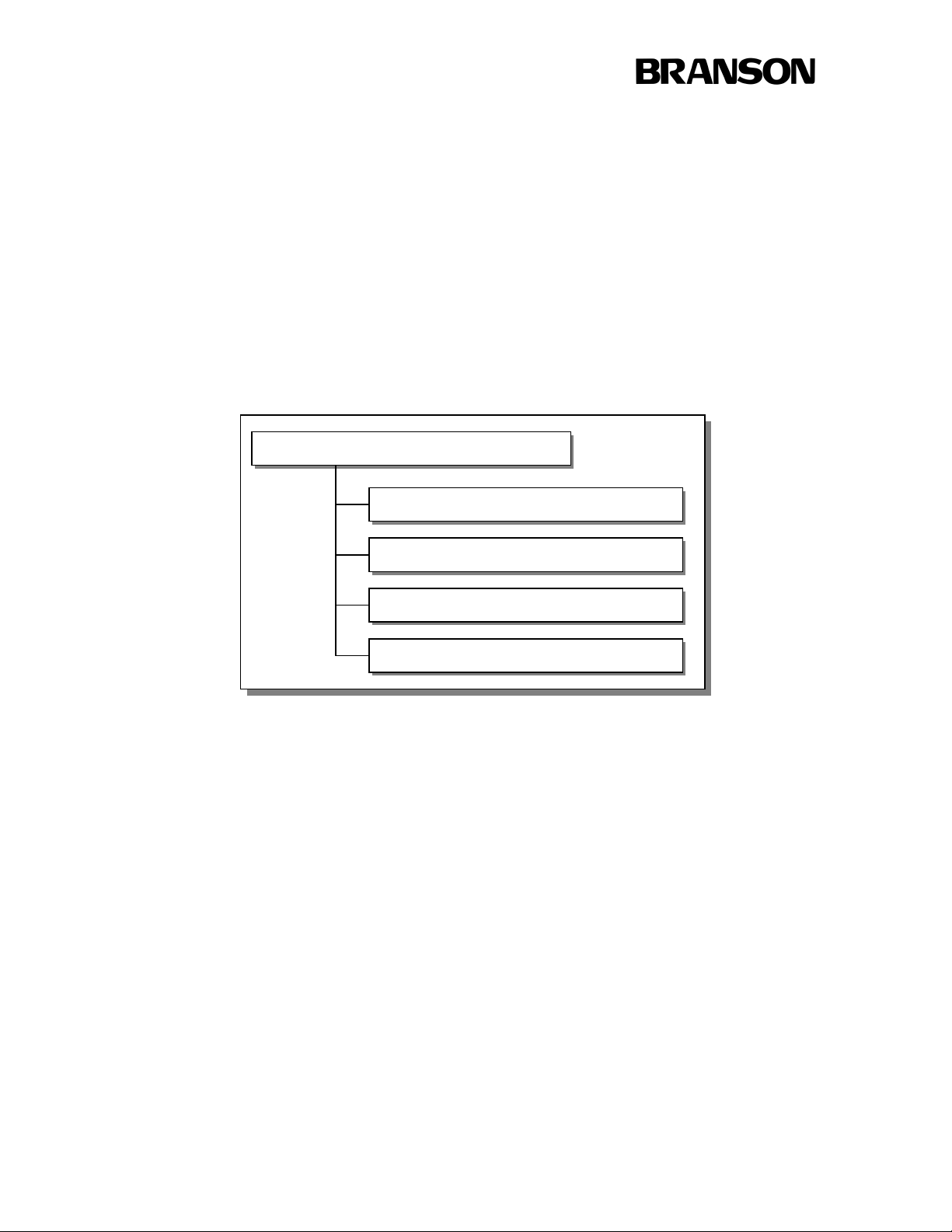
application. It also documents other Instruction Sets used in the manual. The figure below
illustrates how the manual is organized.
BRANSON Metal Welding Product Manual
Special Information Instruction Set
General Information Instruction Set
Actuator Instruction Set
Controller Instruction Set
(Other) Instruction Set (s)
Instruction Set for Special Information Page 3 of 8

BRANSON Metal Welding
Product Manual- Special Information
Using this manual:
It is highly recommended that you read and understand the contents of this manual prior to
operating your BRANSON Metal Welding system. Each Instruction Set has a table of contents
and is intended to logically group information in a manner which the user will find convenient.
Classification of Hazards:
The safety indications in this manual are divided into different classes. The figure below shows
the assignment of symbols (pictograms) and signal words to the specific hazards and its potential
consequence.
PICTOGRAM SIGNAL
WORD
ATTENTION !
DANGER !
NOTE
A potentially dangerous situation
that could cause injury to persons
and serious damage to equipment.
A situation that may cause damage
to the equipment
Useful information, an application
hint or other important or useful
information.
DEFINITION
Instruction Set for Special Information Page 4 of 8
BRANSON Metal Welding
Actuator
Shuttle
Controller
Power Supply
PLC
Product Manual- Special Information
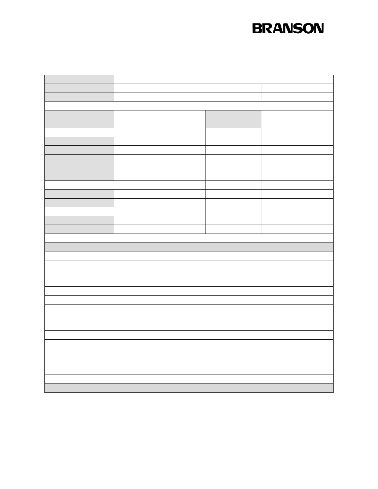
System Specification Sheet:
Sales Order
Customer
Create Date
Type
Serial Number Program No N/A
Type TouchScreen
Serial No
Firmware Type Welder
Firmware Version
Firmware Lang Multi Lingual
Type N/A
Serial Number N/A
Type N/A
Program Number N/A
Part Number Description
101-135-067R Converter
Horn
Tip
Tip Nut
Anvil
See Table 1 Booster, High Gain
To serve you better, please be aware of the following:
All tools have a 5 to 6 week lead time.
Prices are subject to change without notice.
An additional fee may be charged for expedited service.
MWX100
Type N/A
Instruction Set for Special Information Page 5 of 8
BRANSON Metal Welding
Product Manual- Special Information
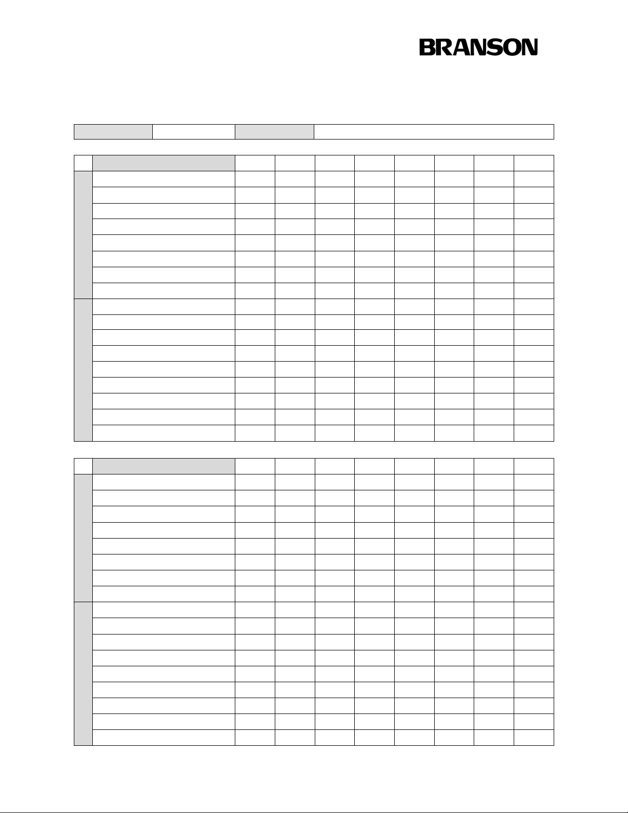
Parameter Preset Information
Sales Order «SalesOrder»
Customer
«Customer»
Name or preset Number
Energy (joules)
Force (psi/bar)
Pressure (psi/bar)
Amplitude (microns)
Squeeze Time (ms)
Pre-Burst (ms)
Hold Time (ms)
Welding Parameters
After Burst Delay (ms)
After Burst Duration (ms)
Weld Time Min. (ms)
Weld Time Max. (ms)
Weld Power Min. (watts)
Weld Power Max. (watts)
Pre-Height Min. (mm)
Pre-Height Max.(mm)
Post Height Min.(mm)
Quality Monitoring
Post Height Max. (mm)
Instruction Set for Special Information Page 6 of 8
BRANSON Metal Welding
Product Manual- Special Information
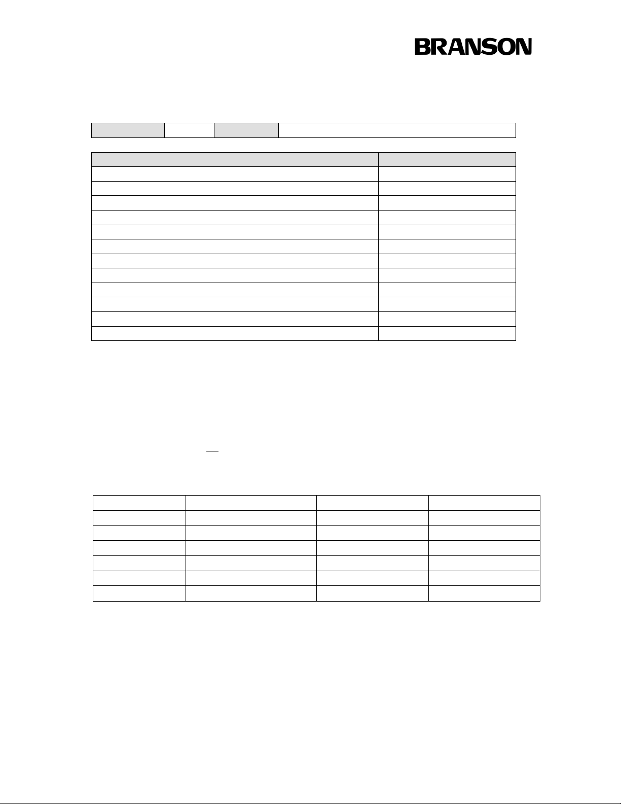
File Attachments:
Sales Order Customer
Description File
Assembly Drawing 159-132-341
File Attachments are included at the end of this instruction set.
Tooling Table:
The (computer) file name of this manual contains a two digit suffix number.
Example: DCM01241- ##. PDF
Use the suffix number from Table 1 to determine the Booster used on your welder.
DCM01241- Booster Type, Color Part Number Gain (ref only)
-01
-02
-03
-04
-05
-06
Super High Gain, Silver
High Gain, Gold
Medium High Gain, Blue
One-to-One, Red
Medium Low Gain, Blue
Low Gain, Black
Table 1
17100-00-416 2:1
17100-00-216 1.67:1
17100-00-316 1.17:1
17100-00-016 1:1
17100-00-516 0.75:1
17100-00-116 0.5:1
Instruction Set for Special Information Page 7 of 8

BRANSON Metal Welding
Product Manual- Special Information
Special Instructions:
Instruction Set for Special Information Page 8 of 8

BRANSON Metal Welding
Product Manual- General Information
General Information and Instructions
Document Number DCM00003
Last revised 03/27/2012 LAW
Use of this document is intended for use with all Branson Metal Welding products.
Branson Ultrasonics Corporation
41 Eagle Road
Danbury, Connecticut 06813-1961 U.S.A.
(203) 796-0400
(203) 796-0810 FAX
http://www.bransonultrasonics.com
This document is intended for use in conjunction with others to form a complete manual
for your Branson system.
Introduction:
This Instruction Set includes common information which relates to Branson products. It will help
you in setting up your system and to understand the fundamentals of the ultrasonic metal welding
process.
Portions of this section may be superseded by more specific and detailed information
provided in other Instruction Sets.
Instruction Set for General Information Page 1 of 30

BRANSON Metal Welding
Product Manual- General Information
Table of Contents
Introduction: ...............................................................................................................................1
Table of Contents ........................................................................................................................2
Thank You: .................................................................................................................................3
Warranty: ....................................................................................................................................4
Intended Use: ..............................................................................................................................5
Safety, Personal: .........................................................................................................................5
Safety Devices .........................................................................................................................5
Emergency Stops: ....................................................................................................................5
Safety Guidelines: ....................................................................................................................5
Maintenance Safety:.................................................................................................................6
Safety, System: ...........................................................................................................................6
System Protection Monitoring (SPM) ......................................................................................6
Thermal Switch........................................................................................................................6
Daily Functional Safety Checks: ..............................................................................................6
Unpacking, Handling & Installation: ...........................................................................................7
If damage has occurred: ...........................................................................................................7
System Location: .....................................................................................................................7
System Assembly: ...................................................................................................................7
Operating the System: .................................................................................................................8
Troubleshooting: .........................................................................................................................9
Weld Overload .........................................................................................................................9
Low Air Pressure .....................................................................................................................9
Ready Check ............................................................................................................................9
Troubleshooting Guide .......................................................................................................... 10
Periodic Maintenance ................................................................................................................ 13
Contacting Branson: .................................................................................................................. 14
Spare Parts & Replacement Tooling: ...................................................................................... 14
Questions or Problems: .......................................................................................................... 14
Returning Equipment: ............................................................................................................ 15
Return Authorization Form ................................................................................................. 16
New Applications: ................................................................................................................. 17
Evaluation Request Form .................................................................................................... 18
Terminology: ............................................................................................................................ 19
Ultrasonic Theory: .................................................................................................................... 24
What Is An Ultrasonic Weld?................................................................................................. 24
How Does It Work? ............................................................................................................... 24
Instruction Set for General Information Page 2 of 30

BRANSON Metal Welding
Product Manual- General Information
Thank You:
Thank you, and congratulations on selecting Branson MWX100/ ULTRASPLICE Systems for
your welding production. This system has been developed to produce the highest quality welds at
the lowest cost per weld.
If you should experience difficulty or have any recommendations for improvement, please do not
hesitate to contact us.
Please be advised that the MWX100/ ULTRASPLICE machine is protected under the United
States and International patents listed below. This operator’s manual is also protected by
copyright and may not be copied without prior written permission by Branson.
Trademarks
MWX100 and
ULTRASPLICE
Copyright
MWX100 Computer Software
and the MWX100 Manual
are registered trademarks of
Branson Ultrasonics Corporation
are copyrighted 1994,1995,1996,1997 by
Branson Ultrasonics Corporation
Instruction Set for General Information Page 3 of 30

BRANSON Metal Welding
Product Manual- General Information
Warranty:
Branson Ultrasonics warrants this equipment to be free from defects in material and
workmanship for one (1) year from date of original delivery by Branson or by an authorized
representative when used in accordance with written instructions. Any unit which proves
defective during this period will be repaired or replaced free of charge at the sole discretion of
Branson Ultrasonics, F.O.B. Danbury, Connecticut or an authorized repair station as advised by
Branson. This is the buyer’s sole and exclusive remedy. The defective unit must be returned
properly packed with all transportation charges prepaid.
Expendable tooling produced by Branson such as the horn, tip and anvil will wear at varying
rates depending upon the application and duty cycle. For this reason, Branson warrants that all
tooling complies with specifications on design and materials but cannot guarantee its useful life
for a fixed period of time.
The warranty provisions contained herein are expressly in lieu of all other warranties, express or
implied. THERE ARE NO IMPLIED WARRANTIES OF MERCHANTABILITY OR
FITNESS FOR A PARTICULAR PURPOSE MADE IN CONNECTION WITH THE
EQUIPMENT TO BE DELIVERED THEREUNDER.
This warranty is limited to the original purchaser and is not transferable.
BRANSON Ultrasonics will not be liable for any consequential damages claimed in relation to
the purchase or warranty of the equipment to be delivered thereunder. Branson will not be liable
for any injury to persons or property caused directly or indirectly by the use of the equipment
delivered thereunder.
Horns fabricated by Branson for use in Branson equipment are manufactured to exacting
parameters and tuned to vibrate at the equipment’s ultrasonic operating frequency. An
improperly tuned horn can cause undue stress or damage to the converter and power supply.
Contact your Branson representative or Branson’s world headquarters in Danbury, Connecticut,
should you have any questions concerning horn qualifications.
Authorization to return equipment for repair is required. A Return Authorization Number must
be obtained from Branson’s Service Department. Equipment being returned for repair must be
packaged in the original carton(s) to protect it from damage and returned freight prepaid. Any
damage that is sustained as a result of improper packaging may void the warranty and is the
sole responsibility of the customer.
For questions relating to warranty or repair please contact our Repair Department.
Instruction Set for General Information Page 4 of 30

BRANSON Metal Welding
Product Manual- General Information
.
Intended Use:
This equipment is for the joining of metal parts using ultrasonic energy. A complete system
includes an actuator, controller and tooling (which delivers mechanical energy to the work
pieces). Some systems also include special fixturing and machine automation. Branson systems
may only be utilized to weld soft, ductile, metal parts together with Branson-supplied weld
tooling (such as horns, tips, anvils, and converters) unless an explicit, written, contrary
agreement between the ordering party and Branson has been consummated.
Safety, Personal:
Safety Devices
The removal, bridging or disabling of safety devices is not condoned for production operation.
Individual safety devices mentioned below may only be disabled if super-ordinate safety devices
are employed in their place.
Emergency Stops:
In case of danger, hit the red, emergency stop which is found on the red, top portion of the foot
pedal. The actuator, power supply and related fixturing are returned to the “Home” position. If
dual anti-tie start buttons are used, there must be a red emergency stop associated in line. Free
access to the emergency stop button must be maintained.
Controller Cover
The power supply is equipped with a top cover which should only be removed for maintenance
and installation purposes.
Safety Guidelines:
For operating safety, please observe the following precautions:
• Plug the power supply into a grounded electrical supply to avoid electrical shock.
• Ensure that no one is in contact with system moving parts when operating.
• Keep hands away from the horn tip as high force and ultrasonic vibration can cause injury to
hands and fingers.
• Do not test ultrasonics when the converter is removed from the actuator. Without the
converter there is the danger of damage or shock.
• Before adjusting or repairing the ultrasonic stack or power supply, disconnect the line power.
• Any unauthorized modification of the units control circuitry or wiring may cause a
malfunction, which could result in injury to operating personnel.
• Do not operate the equipment until repairs and adjustments have been made and the
equipment is in good working order.
Instruction Set for General Information Page 5 of 30

BRANSON Metal Welding
Product Manual- General Information
Maintenance Safety:
Safety devices, especially covers, guards and ground cables should only be removed when it is
absolutely essential for the completion of maintenance work. If safety devices were removed
prior to starting maintenance work, be sure to re-install those devices after finishing the
maintenance work. The following installation and maintenance operations must be performed
prior to any disassembly of equipment:
• All system components must be disconnected from the main electrical supply
• Remove the plug from the main electrical supply and secure it from being re-inserted
accidentally.
• All system components must be disconnected from the main air supply
• Disconnect the air hose from the main air supply and release system air pressure via the
pressure regulator.
Safety, System:
System Protection Monitoring (SPM)
The SPM (System Protection Monitoring) stops ultrasonics when the power supply has been
overloaded or when inappropriate or defective horns are used.
Thermal Switch
A thermal switch is contained within the power supply to automatically disconnect power to the
machine if the unit gets too hot. This will occur if the exhaust fans from the generator are
inadvertently blocked or clogged.
Daily Functional Safety Checks:
• Check the machine tip and anvil for any signs of grinding, cracking, or galling that could be
the result of misalignment or tooling contact. Replace tooling that has excessive wear.
• Check for any loose material or debris in the welding cavity, cleaning it out.
• Check all parameter settings on the controller to ensure they are properly set for the weld to
be made.
• Drain water and contaminants from the airline filters as necessary
Instruction Set for General Information Page 6 of 30

BRANSON Metal Welding
Product Manual- General Information
Unpacking, Handling & Installation:
Unpack the Actuator and Touchscreen Controller. Remove the top cover of the power supply
and check if any components became loose during shipment.
If damage has occurred:
Notify the shipping company immediately. Retain packaging materials for inspection and
possible re-use.
System Location:
Locate the Touchscreen Controller in an area away from radiators or heating vents. Allow
sufficient clearance in back of the controller to access the connectors. Observe the following:
• Do not block the exhaust or air intake areas. Proper air circulation is necessary to maintain a
safe operating temperature.
• Only operate the controller within an ambient temperature range of 41°F to 122°F (5°C to
50°C).
• Verify that neither dust nor dirt are allowed to restrict the flow of air exhaust or air intake.
Clean the air ports as necessary.
If the temperature of the power supply exceeds the recommended operating range, a thermal
switch will stop ultrasonics and the power supply will display an Overload alarm. Ultrasonics
will remain off until the power supply cools to a safe operating temperature and the RESET
button is pressed.
If the environment is excessively dirty or oily, contact Branson for assistance. Special
Touchscreen Controller enclosures, filters (i.e. filter/separator/regulator), and other equipment
are available.
System Assembly:
Connect the actuator system per the Hookup diagram contained in the Special Information
Instruction Set. Verify that connections are complete and correct before proceeding. Plug the
Controller into a proper power source. See the Touchscreen Controller Instruction Set for power
specifications, plugs and receptacles used.
To prevent the possibility of an electrical shock, always plug the power supply into a
grounded power source. Be sure the power switch is in the Off position before making any
electrical connections.
Connect the system to a clean (5 micron air filter with 0.5 micron mist separator), dry, 80 psig
(5.5 bar) minimum air supply. See the Actuator Instruction Set for information on the set up of
application tooling and the use of this equipment for ultrasonic welding.
Instruction Set for General Information Page 7 of 30

BRANSON Metal Welding
Product Manual- General Information
Crash Gap Adjustment:
In most applications, adjustment of the gap between the ultrasonic Horn Tip and the Anvil is
factory set to prevent these surfaces from contacting each other when no parts to be welded are
present and the foot pedal is depressed. A poorly adjusted crash gap can cause serious damage to
the tooling. See the Actuator Instruction Set for proper setup instructions.
Operating the System:
With all proper connections made and with tooling properly set up, welding may be performed.
In most instances it is likely that Branson has developed weld settings for your application and
stored them as presets in the controller prior to shipping. See the Touchscreen Controller
Instruction Set for information on retrieving presets. For other weld parameter information
pertaining to your system, see the parameter preset page included in the Special Information
Instruction Set.
Instruction Set for General Information Page 8 of 30

BRANSON Metal Welding
Product Manual- General Information
Troubleshooting:
This section shows how to fix some of the possible errors and problems which may occur in
normal use of the MWX100/ Ultrasplice system.
Weld Overload
Weld overloads are premature shut downs of the power supply. Overloads signify excessive
loads and must be corrected if continued reliability of the equipment is to be maintained.
Hardware internal to the supply are controlling this function and it can not be defeated.
The control system analyzes the end of weld characteristics to check for overloads. If the system
determines an overload an alarm occurs. The control halts action until the system is reset.
Some of the possible causes for overloads are:
• The tool clearances are too small, horn and anvil touch during welding
• Excessive air pressure with low amplitude
• Defective Stack assembly
• Defective Power Transistors in power supply
Low Air Pressure
The control system and its components were designed to run with a clean air supply of from 90
to 120 psi. The control system monitors the air pressure from the low air pressure switch
(optional). The low pressure threshold is set from the controller. An alarm occurs when
incoming line pressure the drops below the set pressure.
Ready Check
The system undergoes a Ready Check operation at every startup, the end of every weld, and at
the exit of Setup mode. This procedure checks the height encoder position. If an incorrect height
value is returned, an alarm occurs.
Some of the possible causes of a Ready Check alarm are:
• The horn is stuck in the closed position
• Maintenance has moved the height encoder to an out of limit condition
• Defective encoder or electronics
• Encoder not plugged in to its connector
Instruction Set for General Information Page 9 of 30

BRANSON Metal Welding
Product Manual- General Information
Troubleshooting Guide
PROBLEM SOLUTION
System will not turn on. Power cable plugged in.
Power turned on at the outlet.
Check internal fuses on the Controller Line
Board.
Plant fuse fails or circuit breaker trips
when plugging the unit into an electrical
outlet.
Plant fuse fails or circuit breaker trips
during weld cycle
Line fuse fails. Check fuse current rating, replace if
Horn will not move down or up. System not connected to air supply.
Get Emergency Stop when system is
turned on.
No Sonics when test button is pressed. RF Cable connected.
No sonics during weld cycle Check all cable connections.
Overloads when welding Stack not tuned properly.
When touching the system you get a
slight electrical shock.
Inspect power cord, replace if shorted.
Check line filter, replace if failed.
Check current rating of the plant fuse or the
circuit breaker, replace if failed.
incompatible.
Check fan motor, replace if failed.
Air not turned on.
Check Emergency Stop Switch.
All cables properly connected.
Press red switch on foot pedal. (if system is
equipped with one)
Check RF cable for broken wire.
Ribbon cable in power supply between SPM and
programmer unplugged.
Check start cable for broken wires.
Check inside power supply for loose start cable
from rear of unit to programmer board.
Check thermo switch in power supply.
Tooling not set up properly.
Crash gap not set properly.
Tip nut cracked, replace if needed.
Check weld parameters.
Check stack interfaces for fretting.
Check for loose or failed horn or booster, tighten
or replace as necessary.
Inspect power cord, replace if needed.
Inspect system ground, repair if needed.
Instruction Set for General Information Page 10 of 30

BRANSON Metal Welding
Product Manual- General Information
Tooling heats up after machine runs a
while.
Low weld strength. Check weld parameters.
Excessive welding. Reset parameters.
Time limit error or peak power error
displayed after weld cycle.
Squealing sound during welding or when
test key is depressed
Weld heights are inconsistent Re-calibrate encoders with 1mm gauge.
Horn is stuck in down position Check air pressure.
Air leaking from machine. Ensure all air line connections are tight.
Unusual sound during weld cycle. Check tooling gap.
Cooling air is not turned on or is not on long
enough.
Cooling air is not directed at tooling.
Check tooling gaps.
Check knurl on tooling. If worn replace
tooling.
Increase Energy.
Check the Down stop adjustment.
Check for part contamination.
Ensure all hardware is tight.
Reset amplitude.
Reset pressure.
Measure and re-calibrate amplitude display.
Reset limits.
Check tip, rotate or replace if worn.
Check anvil for wear, rotate or replace if worn.
Check air pressure setting.
Check up stop for proper adjustment.
Process settings have to be opened up due to
part variance or limits should be adjusted
according to the part/wire being run.
Check anvil clamp for proper torque.
Check plate screws and tighten or replace.
Check cover plate screws and tighten.
Reset gaps.
Re-square horn/tip and reset gaps.
Reset horn tip and gap.
Ensure the connector for the encoder is tightly
plugged into the actuator card.
Ensure air lines are installed properly.
Check for kinks in air lines.
Check for cracked or broken air lines.
Check converter.
Check stack assembly.
Instruction Set for General Information Page 11 of 30

BRANSON Metal Welding
Product Manual- General Information
Squealing sound from power supply when
unit is turned on.
Maintenance counter alarm. Reset maintenance counter.
Actuator arm moves sluggish Check air lines for contamination.
System has READY CHECK message The horn is stuck in the closed position.
Time, height and energy inconsistent. Switch to energy mode & open height window.
Check cooling fans in rear of unit
NOTE: Air must be filtered to 5 microns and be
oil and water free.
Check solenoid valve, replace if needed.
Check air regulator.
Maintenance has moved the height encoder to
an out of limit condition.
Defective encoder or electronics.
Encoder not plugged into the actuator card.
Make some sample welds. Check the time and
the height of the welds for consistency. If the
time or weld thickness varies greatly, check the
air regulator.
Instruction Set for General Information Page 12 of 30

BRANSON Metal Welding
Product Manual- General Information
Periodic Maintenance
In order to maintain optimum operating conditions, it is important to perform various
maintenance and equipment inspections at periodic intervals. Please observe the following
recommendations.
Daily:
• Drain water and contaminants from the airline filters, if required.
Every Tool Rotation:
• Inspect the clamping surfaces of the Tip, the Tip Nut
and the Horn for fretting.
• Vacuum and clean out any copper residue or dirt in the actuator.
After one million cycles:
• Vacuum and clean inside of power supply
• Calibrate pressure regulator.
• Clean and torque the stack interface.
• Calibrate amplitude.
FSR Assembly
Air Filter/Separator/Regulator (Optional Branson Part #207-020) should be serviced after 1 year
or when a pressure drop of 15 psi is reached.
• Disconnect the air supply.
• Remove and clean out filter bowl with a clean rag.
• Replace the white filter element and re-assemble.
• Remove and clean out separator bowl with a clean rag.
• Replace brass-colored filter element and reassemble.
• Reconnect air supply.
Do not use solvent to clean filter bowls
Clean the air filter bowl with a mild household soap only. The bowl is made from a
polycarbonate material, which can rupture if exposed to synthetic lubricating oils solvents or
harsh chemicals. The bowl is rated for a maximum line pressure of 140 psig (1043 kPa) and a
maximum temperature of 120°F (49°C).
Instruction Set for General Information Page 13 of 30

BRANSON Metal Welding
Product Manual- General Information
Contacting Branson:
Spare Parts & Replacement Tooling:
Spare parts or replacement tooling for the ultrasonic welding system may be ordered directly
from Branson. A spare tooling specification sheet is included in the Special Information
Instruction Set. Additional part listings are contained in the Actuator and Touchscreen
Controller Instruction Set sections of this manual.
Branson will work with you and recommend components you need and should carry in inventory
based upon your manufacturing philosophy and or production needs. We will quote price,
delivery and can coordinate special arrangements such as expedited service or blanket orders.
When Ordering Spare or Replacement Parts have the purchasing agent Fax the order to us with
the following information provided:
• Purchase Order Number,
• Branson Part Number, Quantity, and Date Required,
• Ship To Information, (including “Ship to the Attention of”)
• Bill To Information
• Shipping Instructions, (such as air freight, truck, etc.)
• Special Instructions, (such as “Hold at Pick-Up Counter and Call” -- Be sure to provide a
name and a phone number)
Questions or Problems:
If you have any questions or are experiencing a problem, call the local Branson field sales and/or
service representative. He or she will be familiar with your equipment and application and, in
most cases, will be able to help you. He or she may have the replacement part you need, in
stock, that will return your system to operation in the shortest possible time.
If necessary, the representative will contact Branson for additional service and, in some cases,
will put you into contact with the appropriate personnel. If the local representative is unavailable,
please call us directly.
Before you call, take the following steps:
• Have this manual with you.
• Know how your system has been set up and equipped, including your MBOS version.
• Be able to describe the situation or problem.
• Have a list of steps that you have already taken.
• Have a list of spare parts in your inventory
• Have the name and phone number of the Local Branson Representative
Instruction Set for General Information Page 14 of 30

BRANSON Metal Welding
Product Manual- General Information
Returning Equipment:
In order to properly and efficiently handle an equipment return to Branson, the following
procedure must be followed. Contact your Local Sales Manager or Branson Customer Service
for assistance. Proper handling and identification of your equipment will expedite servicing
and/or return.
Using the Return Authorization Form, (next page), complete the following:
• Customer Information Section
• Description of Problem
• Equipment Information
Call Branson and Receive a Return Authorization Number (RA#) from Branson Customer
Service.
• Properly package the equipment to prevent damage
• Clearly mark the RA# on the outside of the package
• Include a copy of the completed Return Authorization Form inside the package
• Return general repairs by any convenient method. Send priority repairs via Air Freight
• Prepay the transportation charges, (FOB Danbury, CT)
Instruction Set for General Information Page 15 of 30

BRANSON Metal Welding
Product Manual- General Information
Return Authorization Form
Customer Information Authorization Information
Customer name: Return Authorization No:
Address:
Contact:
Phone:
Fax:
Description of Problem:
Equipment Information:
Machine Type:
Machine Serial Number:
Date of Original Purchase:
Part Number of Component:
PO Number for Repair:
Do not ship to Branson without an RA
number. Mark the RA number on the shipping
label. Please fax a copy of this completed
form to Branson Customer Service prior to
Shipping.
Assigned By:
Special Instructions:
For Branson Use Only
Under Warranty
Billable Repair
Charge Repair to Sales
Sold Replacement Part
Instruction Set for General Information Page 16 of 30

BRANSON Metal Welding
Product Manual- General Information
New Applications:
Branson is always eager to work with you on a new ultrasonic application. Whether it be a
manual workstation, a semi or fully automated system, Branson has the personnel and technical
competence to support your requirements. Branson’s application laboratory, product and
automation engineering, customer service and manufacturing capabilities are second to none.
Branson is the world leader in ultrasonic metal welding and our business philosophy is practiced
to assure customer success.
Application assistance is always available. For initial application review, contact your Local
Sales Manager who can indicate initial feasibility and assist you in completing the Ultrasonic
Weld Evaluation Request Form, (next page). Please complete one (1) request form for each
application.
Please copy the attached Ultrasonic Evaluation Request Form (next page), complete the
customer and application information section and forward it to Branson along with enough
component material to produce 24 assemblies, (if this is not practical please advise). A
feasibility evaluation will be performed and samples returned, for review, along with a system
quotation/ proposal. Be sure to include drawings of the completed assembly and include the
electrical, mechanical, and production requirements. Complete the form as completely as
possible. The Branson Sales Representative can assist you.
Instruction Set for General Information Page 17 of 30

BRANSON Metal Welding
Product Manual- General Information
Evaluation Request Form
Lab Application No: Date:
Please fill out this form with at least 24 samples parts for an ultrasonic weld analysis
Name:
Company:
Address:
City:
Telephone:
Component Description:
Part 1 Part 2
Material:
Hardness:
Plating:
Insulation:
Application Requirements:
Production Rate: (parts/hr)
Location tolerance: (in)
Is weld appearance important:
Pull Strength (lbs)
Drawing Notes:
This information to be completed by Branson
Representative:
Telephone:
Return samples to: Representative Customer
Sales Engineer:
Applications Engineer:
Instruction Set for General Information Page 18 of 30

BRANSON Metal Welding
Product Manual- General Information
Terminology:
Actuator: A mechanical device which houses the converter/booster/horn (stack) assembly in a
rigid mounting and is utilized to move the stack up or down. This allows for precise control of
welding pressure for efficient while delivering mechanical vibrations from the ultrasonic stack to
the work piece(s).
After Burst: A short duration (burst) of ultrasonic energy that begins after completion of the
AFTER BURST DELAY. (Also See: AFTER BURST DELAY & AFTER BURST
DURATION)
After Burst Delay: The amount of time, in seconds, between the completion of the ultrasonic
welding cycle and the start of the AFTER BURST. (Also See: AFTER BURST & AFTER
BURST DURATION)
After Burst Duration: The amount of time, in seconds, that AFTER BURST energy is
delivered. (Also See: AFTER BURST & AFTER BURST DELAY)
Amplitude: Amplitude is the peak-to-peak displacement of mechanical motion as measured at
the face of the horn tip. Amplitude is measured in thousandths of an inch or in microns. (i.e. A
standard 40 kHz converter produces approximately .0004” or 10 microns of amplitude), Inches x
25,400 = microns. -- With ‘Advanced Power Supply’ this is adjustable depending on system
frequency and application tooling.
Anti-Node: The anti-node is the area of the horn and booster that exhibits maximum
longitudinal displacement and where the internal dynamic forces are equal to zero. This area is
at the face and back surface on half-wave technology.
Anvil: A device specially designed to grip the lower component and hold it stationary against
the energy of vibration(s) which allows a weld to be created.
Baud Rate: A communications measure describing the speed at which signals are transmitted
serially (the number of signal events per second).
BBRAM: Nonvolatile random access memory (battery back-up random access memory).
Equipped with long life built in batteries, this memory area preserves weld parameters and menu
settings when the system is powered off. (also known as BBR)
Booster: The central component of an ultrasonic stack assembly. A device which transfers
mechanical energy from the converter to the ultrasonic horn. The booster will, depending on
design, increase, decrease, or maintain the specific energy (amplitude) as received from the
converter.
Calibration: The process of adjusting a device to a known position for purposes of inspection
and/or monitoring position, direction, speed, and/or velocity.
Instruction Set for General Information Page 19 of 30

BRANSON Metal Welding
Product Manual- General Information
Clock: An electronic circuit that generates timing pulses to synchronize the operations of
various other circuits in a device(s).
Communications: Transmission of information between points of origin and reception without
alteration of the sequence and or structure of that information content.
Consumable Spare Tooling: The tooling portion of the ultrasonic system that wears and
requires replacement due to production use. This includes but is not limited to ultrasonic horns,
replaceable tips, anvil, and positioning mask. A Spare Tooling Specification Sheet is included
within the Operation Manual to document the spare tooling for a specific metal welding
application.
Continuous Sonics Mode: A system setting in which the power supply will deliver ultrasonic
electrical energy until the start signal is terminated.
Controller: The portion of the welding system that provides specific settings & instruction(s) to
the overall welding system.
Converter: A device which utilizes a lead-zirconate-titanate electrorestrictive element to
change high frequency electrical energy into high frequency mechanical energy.
Counter: A programmable device used to monitor system cycles and alert personnel when
specific conditions are met.
Data: Any representation(s) of instructions, characters, information, or analog quantities to
which meaning may be assigned
Default: A chosen system setting or parameter in which the system does not require external
data input. In some cases the default value will be changed based upon equipment use.
Dynamic Spring: An, adjustable, energy storage mechanism (shock absorber) which allows for
stack follow through upon engagement of application tooling with the work pieces to be welded.
Energy: Energy is the area beneath the ultrasonic power curve and is calculated in joules,
(Watts X Seconds = Joules). When the ultrasonic welding system is setup in the “Weld In
Energy” mode the system will deliver the amount of energy as programmed. NOTE: The
maximum (default) time allowed for delivering ultrasonic energy is five (5) seconds.
Energy Mode: A welding method in which the ultrasonic power supply is active until the
required amount of energy is delivered (See ENERGY)
Fixture: A device for positioning and or holding a component for assembly.
Force: The amount of mechanical pressure that is used to deliver, (bring down) the mechanical
actuator. This programmed force is also called TRIGGER FORCE and is used to engage the
knurl pattern into the component part(s) prior to the initiation of ultrasonic energy.
Instruction Set for General Information Page 20 of 30

BRANSON Metal Welding
Product Manual- General Information
Frequency: The number of complete oscillations per second expressed in Hertz (Hz) or
kilohertz (1 kilohertz = 1000 Hz). Typically 20 kHz or 40 kHz.
Gain: The ratio of the amplitude of motion produced by the converter and delivered by the horn
is called the gain. It is determined by the difference in mass on either side of the nodal point.
Hand Shaking: The procedure (signal exchange) when a connection is established between two
electronic devices. A common example is the signal exchange between a terminal and a
MODEM. These signals (hardware and software) are used to control the flow of data (start/stop)
between devices.
Height: A display value, in millimeters (mm), as registered by a linear encoder upon completion
of an ultrasonic welding cycle. -- Programmable, in millimeters, with Upper Control Limit &
Lower Control Limit
Height Encoder: A device utilized to monitor position, direction, speed, and/or velocity.
Horn: An acoustically designed metal tool that delivers mechanical energy from the converter/
booster into the work piece. Most applications utilize half wave technology, (40 kHz = 2.2” ±,
20 kHz = 5.5” ±).
Hold Time: The amount of time after delivery of ultrasonic energy until the stack tooling begins
to retract from the component material(s).
Joint: The welded surfaces
Linear Height Encoder: (See: Height Encoder)
Loading Meter: A meter which indicates the power drawn from the ultrasonic power supply.
Maintenance Counter: A programmable device used to alert production personnel of the need
to review/ inspect application tooling and/or the ultrasonic system for preventive maintenance
purposes. The device increments one (1) count for each system cycle. (See: Counters)
Mode: The method of operating the system (also see WELDING MODE)
Node: The node is the area of the horn, (and booster), that exhibits no longitudinal displacement
and where the internal dynamic forces are at the maximum. This area is in the center location on
half-wave technology.
Parameter(s): Programmable units used to control and or monitor the ultrasonic process. -Include but not limited to ENERGY, FORCE, PRESSURE, AMPLITUDE
Parts Counter: A programmable device used to monitor system cycles and alert personnel
when specific conditions are met. (See: Counters)
Instruction Set for General Information Page 21 of 30

BRANSON Metal Welding
Product Manual- General Information
Peak Power: Peak power is the maximum amount of power in watts that was required to keep
the ultrasonic stack in motion during the weld cycle.
Power: Power, measured in watts, is a function of pressure and amplitude. The amount of
power, (watts) required to keep the ultrasonic stack in motion is monitored and used to develop a
power curve. This power curve is used to calculate the amount of energy delivered/ dissipated,
(Watts = Joules / Time). The power as displayed on the control box is peak power.
Power Supply (Ultrasonic): An electronic device that converts 50/60 cycle electrical current
into 40 kHz, (40,000) or 20 kHz, (20,000) cycles per second high frequency electrical energy.
Power Supply Overload (Ultrasonic): The point or limit at which the amount of power in
watts, required to keep the ultrasonic stack in motion, exceeds the available power from the
power supply. The system will go into an overload condition in order to prevent system damage.
Preheight: A pre-sonic inspection display, in millimeters (mm), as registered by a linear
encoder prior to initiation of the ultrasonic welding cycle. -- Programmable, in millimeters, with
Upper Control Limit & Lower Control Limit
Presets: System memory available for storage and retrieval of welding parameters.
Pressure: The amount of mechanical pressure supplied to the ultrasonic stack assembly while
delivering ultrasonic energy to the components.
Quality Widows & Limits: Programmable values used by the system to compare actual
process data. Actual process data must be within limits or an alarm condition will exist.
Setup Mode: The condition the control box must be in prior to adjusting parameters, quality
windows, and/or any others settings except those contained within the Command Mode.
Squeeze Time : The amount of time after the ultrasonic tooling engages the component(s) and
before delivery of ultrasonic energy. -- Adjustable from 0 - 0.5 seconds
Stress: Stress is the amount of dynamic force per cross sectional area.
Time : Time is the duration of the ultrasonic, mechanical, activity. Time is a component used to
calculate the amount of ultrasonic energy delivered during a weld cycle, (Time = Joules / Watts).
Tip: Device specially designed to grip the upper component, to be welded, and to direct the
ultrasonic energy into the work piece, (Also: Horn Tip & Replaceable Horn Tip).
Tip Nut: Device specially designed to securely clamp a replaceable tip onto the horn.
Trigger Force: (See: Force)
Instruction Set for General Information Page 22 of 30

BRANSON Metal Welding
Product Manual- General Information
Tuning: Adjusting to optimize power supply performance according to resonance frequency,
especially with regard to the horn and converter.
Velocity: The rate of motion at a specific time [velocity = distance / time] (also referred to as
speed)
Weld Mode:
• Weld In Energy: System delivers ultrasonic energy until a predetermined amount of energy,
in joules is dissipated. The system determines energy by calculating the area beneath the
power curve -- Watts x Time = Joules (1 watt per second = 1 joule).
• Weld In Height: System delivers ultrasonic energy until the ultrasonic tooling reaches a
predetermined position.
• Weld In Time: System delivers ultrasonic energy for a predetermined amount of time.
• Welding Parameters: (See: Parameters)
Instruction Set for General Information Page 23 of 30

BRANSON Metal Welding
Product Manual- General Information
Ultrasonic Theory:
What Is An Ultrasonic Weld?
Ultrasonic welding joins metal parts by applying the energy of high frequency vibrations onto the
interface area between the parts to be welded.
How Does It Work?
Electrical Energy is transformed into high frequency mechanical vibration. This mechanical
vibration is transferred to a welding tip through an acoustically tuned horn (Figure 1). The parts
are “scrubbed” together under pressure at 20,000 or 40,000 cycles per second. This high
frequency vibration, applied under force, disperses surface films and oxides, creating a clean,
controlled, diffusion weld (Figure 2). As the atoms are combined between the parts to be
welded, a true, metallurgical bond is produced.
Figure 1 Figure 2
Benefits of Ultrasonic Welding
Ultrasonic metal welding exhibits unique welding properties that include:
• Excellent electrical, mechanical, and thermal connections between similar and dissimilar
metals.
• Low heat build up during the ultrasonic process (no annealing of materials).
• Compensation for normal surface variations of the material.
• Ability to clean surface oxides and contaminants prior to welding.
• Ability to weld large areas using minimal energy.
• Ability to weld thin materials to thick materials.
• Low cost per weld.
Instruction Set for General Information Page 24 of 30

BRANSON Metal Welding
Product Manual- General Information
How Is An Ultrasonic Weld Made?
Although the theoretical process of producing an ultrasonic weld is uncomplicated, the
interactions of the various weld parameters are important and should be understood. When
producing an ultrasonic weld, there are three primary variables that interact; they are:
Time: The duration of applied ultrasonic vibration
Amplitude: The longitudinal displacement of the vibration
Force: The compressive force applied perpendicular (normal) to the direction of vibration
Power required to initiate and maintain vibration (motion) during the weld cycle can be defined
as:
P = F x A
Where:
• P = Power (watts)
• F = Force * (psi)
• A = Amplitude (microns)
*Note:
Force is determined by multiplying:
Force = (Surface Area of the Cylinder) X ( Air Pressure) X ( Mechanical Advantage)
Energy is calculated as:
E = P x T
Where:
• E = Energy (joules)
• P = Power (watts)
• T = Time (seconds)
Thus the complete ‘Weld To Energy’ process would be defined as:
E = ( F x A ) x T
A well designed ultrasonic metal welding system will compensate for normal variations in the
surface conditions of the metals by delivering the specified energy value. This is achieved by
allowing Time (T) to adjust to suit the condition of the materials and deliver the desired energy.
Instruction Set for General Information Page 25 of 30

BRANSON Metal Welding
Product Manual- General Information
Welding To Energy - Why?
Most metal welding applications are produced by ‘Welding To Energy’ in order to compensate
for the various surface oxides and contaminants associated with the metals being joined. In a
few applications ‘Welding To Time’ or ‘Welding To Height’ will yield better results. Since the
majority of all metal welds are produced using energy as the controlling factor we will confine
our discussion to that condition.
Welding to energy is necessary because of the non-metallic oxides that form on the metal’s
surface as well as other contaminates such as grease and dirt. To producing quality welds
reliably it is necessary that the surfaces to be joined are clean. The high frequency scrubbing
action, combined with pressure, cleans the weld interface at the beginning of the weld process.
The following graph (Figure 3) illustrates a weld produced. The weld ‘power graph’ is
sometimes referred to a weld ‘footprint’. It can be used to visualize the weld cycle and assists in
parameter optimization. Graphs from consecutive welds will vary slightly as the system
dynamically adjusts time to accommodate varying surface conditions. The weld power data is
gathered by sampling the power used in 5 millisecond intervals.
Instruction Set for General Information Page 26 of 30

BRANSON Metal Welding
Product Manual- General Information
Power
The converter/ booster/ horn, (stack assembly), requires minimal electrical power to initiate and
maintain motion (vibration) at a ‘no-load’ condition. As the mechanical load increases, the
power required to maintain the mechanical vibration also increases. The maximum power
required during a weld cycle is ‘Peak Power’.
Figure 3
By increasing Pressure and maintaining all other parameters, the mechanical load or force on the
weld joint increases, therefore, the amount of Power required to maintain the vibration of the
stack increases. Subsequently, because of the increased Power Level, less time is required deliver
the same amount of Energy. This relationship is illustrated in the following diagram (Figure 4):
Figure 4
The difference in the appearance of each of the above weld graphs is the result of increased
Power loading. Based upon an increase in Pressure, additional Power is required to maintain the
motion of vibration. Thus, the same amount of energy is delivered in less time. This approach is
typically used to raise the loading of the power supply during a weld cycle to the desired level as
determined by the application.
Instruction Set for General Information Page 27 of 30

BRANSON Metal Welding
Product Manual- General Information
Time:
The time required to deliver the necessary energy is defined as the Weld Time. For most welds,
the time required will be less than one second. If more energy is required and all other weld
parameters are maintained, the weld time will increase (Figure 5).
Figure 5
Amplitude:
An ultrasonic tool is a resonant acoustical device. The term Amplitude is used to describe the
amount of longitudinal expansion and contraction that the tooling endures as it vibrates (Figure
6). The amplitude correlates to the scrubbing action at the weld interface. This scrubbing action
combined with pressure is what advances the weld by a diffusing or mixing of the base materials.
Figure 6
Instruction Set for General Information Page 28 of 30

BRANSON Metal Welding
Product Manual- General Information
As previously mentioned, the converter/ booster/ horn, (stack assembly), requires minimal
electrical power to initiate and maintain vibration in a ‘no-load’ condition. As the amplitude
increases, the power required to maintain the increased velocity of vibration also increases.
Subsequently, because of the increased Power less time is required deliver the same amount of
Energy. This relationship is illustrated in the power diagram (Figure 7):
Figure 7
Resonant Frequency:
The ultrasonic tooling acts as a spring having node points and anti-node points. The mechanical
energy used to vibrate the tool is created by the converter. As the vibrations are propagated
through the acoustical tool, a harmonic resonance is established consisting of nodes and antinodes. This action results in a resonant wave being transferred through the tooling (Figure 8).
The efficiency of the resonant wave transfer depends on the natural resonant frequency of the
horn and is determined by two factors:
• The speed of sound through the material
• The geometric shape of the object
Figure 8
Instruction Set for General Information Page 29 of 30

BRANSON Metal Welding
Product Manual- General Information
Avoiding An Overload Condition: It is possible to increase the Amplitude and or the Pressure
to a point where the power available is not adequate to initiate or maintain vibration under the
given mechanical load. At this point, the power supply will stall resulting in an Overload
condition. Electronic circuits in the system will protect the power supply if this condition exists.
Welding To Time: In specific applications, ‘Welding To Time’ may be desired. As previously
mentioned, there are three primary variables that interact; they are:
• TIME: The duration of applied ultrasonic vibration.
• AMPLITUDE: The longitudinal displacement of the vibration.
• FORCE: The compressive force applied perpendicular (normal) to the direction of vibration.
Generally, welding for a specific time will produce acceptable results when:
• The equipment is installed on an automated production line and each station must complete
its process within a certain time limit.
• Very small low energy welds on clean components are being made.
Welding Temperature: Ultrasonic welding produces a localized temperature rise from the
combined effects of elastic hysteresis, interfacial slip and plastic deformation. The weld
interfaces reach approximately 1/3 the temperatures needed to melt the metals. Since the
temperature does not reach the melting point of the material, the physical properties of the
welded material are preserved. As the ultrasonic welding process is an exothermic reaction, as
welding time increases so does weld temperature.
Instruction Set for General Information Page 30 of 30

Branson Product Manual - Actuator Information
MWX100
Actuator Information and Instructions
Document Number: DCM00056
Last revised: 03/27/2012 LAW
Branson Ultrasonics Corporation
41 Eagle Rd
Danbury, Connecticut 06810 U.S.A.
(203) 796-0400
(800) 888-6089
(203) 796-0380 FAX
http://www.bransonultrasonics.com
This document is intended for use in conjunction with others to form a complete manual
for your BRANSON Metal Welding system.
Introduction:
This Instruction Set includes information for the BRANSON MWX100 actuator. This actuator is
intended for use with a BRANSON controller.
Portions of this section may be superseded by more specific and detailed information
provided in other Instruction Sets.
Instruction Set for Actuator Information Page 1 of 23

Branson Product Manual - Actuator Information
MWX100
Table of Contents
Introduction: ...............................................................................................................................1
Table of Contents ........................................................................................................................2
Mechanical Actuator System .......................................................................................................4
Ultrasonic Stack Assembly ......................................................................................................5
Converter ..............................................................................................................................5
Booster .................................................................................................................................5
Horn .....................................................................................................................................6
Welding Tip (Replaceable Tip Tooling) ................................................................................6
Tip Nut (Replaceable Tip Tooling) .......................................................................................6
Polar Shell & Ultrasonic Stack. .............................................................................................7
Anvil .......................................................................................................................................7
Actuator ...................................................................................................................................7
Application Tooling ....................................................................................................................8
Controls and Adjustments ...........................................................................................................9
Speed Up .................................................................................................................................9
Speed Down ............................................................................................................................9
Cooling Air ..............................................................................................................................9
Adjustment of the Down Stop ................................................................................................ 10
Adjustment of the Up Stop ..................................................................................................... 10
Tool Gap Requirements............................................................................................................. 12
Knurl Pattern Imprint Evaluation............................................................................................... 13
Torque Check............................................................................................................................ 14
Check Welder Performance ....................................................................................................... 14
Establishing Weld Parameters ................................................................................................... 14
Ultrasonic Stack Disassembly ................................................................................................... 15
Ultrasonic Stack Assembly ........................................................................................................ 16
Encoder Board Calibration ........................................................................................................ 19
Calibrate Height ..................................................................................................................... 19
Height Span Adjustment ........................................................................................................ 20
Slide Maintenance ..................................................................................................................... 21
File Attachments ....................................................................................................................... 23
Recommended Spare Components List ..................................................................................... 23
Instruction Set for Actuator Information Page 2 of 23

Branson Product Manual - Actuator Information
MWX100
List of Figures
Figure 1: Equipment Specifications .............................................................................................4
Figure 2: Ultrasonic Stack Assembly ...........................................................................................5
Figure 3: Actuator Slide Mechanism ...........................................................................................8
Figure 4: Speed Controls and Cooling Knob Location .................................................................9
Figure 5: Up/Down Stop Locations ........................................................................................... 11
Figure 6: Tool Gap .................................................................................................................... 12
Figure 7: Knurl Pattern Imprint Evaluations .............................................................................. 13
Figure 8: Cleaning object mating surface direction .................................................................... 16
Figure 9: Exploded Ultrasonic Stack Assembly ......................................................................... 17
Figure 10: Tool Cleaning .......................................................................................................... 18
Instruction Set for Actuator Information Page 3 of 23

Branson Product Manual - Actuator Information
MWX100
Mechanical Actuator System
The MWX100 system is comprised of a power supply and control box, ultrasonic stack
assembly, application tooling, and mechanical actuator. The mechanical actuator is the system
that rigidly holds and moves the converter, booster, and horn assembly known as the ultrasonic
stack. A pneumatic cylinder drives the actuator to apply a precise pressure to the parts to be
welded during the weld cycle.
Specifications
Length
Height
Width
Stroke
Weight
Figure 1: Equipment Specifications
Instruction Set for Actuator Information Page 4 of 23
18.4in (467mm)
14.7in (373mm)
8.5in (216mm)
0.98in (25mm)
49 lbs (22kg)

Branson Product Manual - Actuator Information
Diaphragm
MWX100
Ultrasonic Stack Assembly
Converter
Figure 2: Ultrasonic Stack Assembly
Converter
The 40 kHz electrical energy from the power supply is applied to the transducer element
or converter, which transforms the high frequency electric current into high frequency
mechanical vibrations at the same frequency. The heart of the converter is a leadzirconate-titanate electrostrictive element that, when subjected to an alternating voltage
expands and contracts. The converter’s efficiency of changing electrical energy to
mechanical vibrations exceeds ninety-five percent.
Booster
A booster couples the converter to the horn and helps determine the amplitude of
vibration produced at the face of the horn. The booster is a resonant half-wave metal
device made of titanium or aluminum and is designed to resonate at the same frequency
as the converter with which it is to be used.
A booster has two functions:
1. A rigid mounting for the converter/booster/horn stack
2. An amplitude-of-vibration increaser or decreaser as ultrasonic energy is
transmitted from the converter through the booster to the horn. The ratio of
input to output amplitude is called the gain.
Booster Horn Tip
Springs
Instruction Set for Actuator Information Page 5 of 23

Branson Product Manual - Actuator Information
MWX100
Horn
The horn is a half-wave length resonant metal device that transfers the ultrasonic
vibrations from the booster to the weld tip. The horn is made of steel (titanium for
replaceable tip tooling) and is designed to resonate at 40 kHz. The acoustical efficiency
of the steel and titanium helps to maintain constant amplitude throughout the operating
temperature of the welder. Since the horn is a vital part of the ultrasonic assembly
system, it should not be altered without proper training and advice from BRANSON
Metal Welding. Depending upon the particular application at hand, the horn may be
either a solid horn as shown in Figure 2a, or a Horn with a replaceable tip that can be
rotated or replaced as shown in Figure 2b.
Figure 2a Figure 2b
Welding Tip (Replaceable Tip Tooling)
The welding tip is designed to grip the upper component of the part to be welded, and to
couple the ultrasonic vibrations through that element into the bonding area. Welding tips
are fabricated from high-speed tool steel and heat-treated to precise specifications to
provide maximum life. The tip is coated to further enhance tool life and to provide
corrosion resistance. The patented tip design offers multiple weld surfaces by indexing
the tip on the horn to a new weld area.
Tip Nut (Replaceable Tip Tooling)
The tip nut is made of titanium and is designed to securely clamp the tip onto the horn.
The horn-welding tip-tip nut assembly is an efficient system for transmitting ultrasonic
vibration to the parts to be welded and offers an interchangeable tool at a low cost.
Instruction Set for Actuator Information Page 6 of 23

Branson Product Manual - Actuator Information
MWX100
Polar Shell & Ultrasonic Stack.
The converter-booster-horn assembly, or ultrasonic stack, is supported in a steel Polar
Shell by means of two diaphragm springs. The diaphragm springs are mounted at either
end of the booster and are securely bolted to the Polar Shell. The diaphragm shaped
springs are made from titanium and are acoustically tuned at the 40 kHz operating
frequency. This system permits efficient transmission of ultrasonic vibration along the
axis of the ultrasonic stack while providing rigid mounting.
Anvil
The anvil is made of high-grade tool steel and coated for maximum wear and corrosion
resistance. The patented tool design allows it to be rotated to present multiple weld
surfaces.
Actuator
The ultrasonic stack is mounted into a steel polar block and securely clamped in place.
The polar block is mounted to a crossed roller recirculating bearing which provides
precise vertical travel of the stack assembly, while providing excellent rigidity to resist
any loss of ultrasonic energy in the horizontal direction of sonic vibrations. See Figure 3.
Instruction Set for Actuator Information Page 7 of 23

Branson Product Manual - Actuator Information
Tip
Anvil
Anvil Clamp
Anvil Holder
MWX100
Application Tooling
Application tooling is designed and manufactured to position and weld component
materials to meet customer specifications. Application tooling typically consists of a
horn / tip / tip nut, anvil, anvil clamp, anvil holder, and tool support. See Figure 3.
Tip Nut
Tool Support
Horn
Figure 3: Actuator Slide Mechanism
Instruction Set for Actuator Information Page 8 of 23

Branson Product Manual - Actuator Information
MWX100
Controls and Adjustments
Speed Up
The Speed Up knob, located on the rear of the actuator, controls the upward speed of the
ultrasonic stack. This is useful for raising the stack quickly for other mechanism actions
and for quick part removal.
To DECREASE the upward speed, turn the indicated knob clockwise.
To INCREASE the upward speed, turn the indicated knob counter-clockwise.
Speed Down
The Speed Down knob, located on the side of the actuator, controls the downward speed
of the ultrasonic stack. This is useful to prevent damaging the parts to be welded,
increasing/decreasing cycle times to get better weld results.
To DECREASE the downward speed, turn the indicated knob clockwise.
To INCREASE the downward speed, turn the indicated knob counter-clockwise.
Cooling Air
Do not turn cooling air off completely using the cooling air adjustment knob.
Doing so may damage the converter.
Cooling air is designed to keep the weld area and the converter cooled to a reasonable
temperature during welding.
To INCREASE cooling airflow rate, turn the cooling air control knob counter-clockwise.
To DECREASE cooling airflow rate, turn the cooling air control knob clockwise.
Speed Down
Cooling
Speed Up
Figure 4: Speed Controls and Cooling Knob Location
Instruction Set for Actuator Information Page 9 of 23

Branson Product Manual - Actuator Information
MWX100
Adjustment of the Down Stop
See Figure 5 for location.
The down stop is used as a safety to prevent contact between the Horn and Anvil if the
welder is cycled without the part(s) to be welded. Unless otherwise specified, a 0.004”
(0.10 mm) gap between the Horn and Anvil is recommended.
To adjust the down stop:
1. Loosen the M10 Hex Nut on top of the weld cylinder.
2. Turn the Down Stop Knob counter-clockwise to increase the maximum
downward travel end position.
3. Turn the Down Stop Knob clockwise to decrease the maximum downward travel
end position.
4. Tighten theM10 Hex Nut when the desired down travel location is achieved.
Adjustment of the Up Stop
See Figure 5 for location.
The up stop is used to limit the upward travel of the Horn. Two examples for the use of
the up stop are limiting the upward travel to quicken cycle times and for easier loading
and unloading of components
To adjust the down stop:
1. Loosen the M6 set screw (accessed through the front plate) so that the up stop
screw moves smoothly.
2. Using a long wrench or T-handle, turn the M10 Set Screw counter-clockwise to
increase the maximum upward travel end position.
3. Using a long wrench or T-handle, turn the M10 Set Screw clockwise to decrease
the maximum upward travel end position.
4. Tighten the M6 set screw when the desired upward travel location is achieved.
Instruction Set for Actuator Information Page 10 of 23

Branson Product Manual - Actuator Information
Down Stop
Down Stop
U
p Stop
Up Stop
Up Stop
MWX100
Wrench
Access Hole
M10 Hex Nut
Adjustment
Knob
M10 Set Screw
M6 Set Screw
Figure 5: Up/Down Stop Locations
Instruction Set for Actuator Information Page 11 of 23

Branson Product Manual - Actuator Information
MWX100
Tool Gap Requirements
Tooling includes the Horn (or Horn Tip), Anvil and all surfaces that contact the weld
nugget during processing. The tooling should be inspected to confirm a gap as per the
application tooling set up sheet. If the tooling is in contact during the application of
ultrasonic energy, severe damage may result to the tooling and power supply
This test should be checked whenever the tooling is changed. Also perform this test
whenever you suspect tool contact.
Most tooling that contacts the weld nugget is designed with several weld surfaces. When
one surface is worn and no longer useful, an alternate surface may be used resulting in
extended tool life.
To set the Tool Gap set the air regulator at the same pressure as the weld pressure.
Ensure that there are no work pieces between the Horn and Anvil. Press the SETUP
button on the power supply, then press the HORN button, which will cause the Horn to
descend to its stop. Measure this crash gap as per the application tooling setup sheet.
Press the HORN button again to raise the Horn and adjust the down stop screw located on
the top of the actuator.
Figure 6: Tool Gap
The BRANSON Metal Welding MWX100 is capable of accurate height measurements
and can adjust for weld pressure and crash gap settings. All tool setups especially crash
gap must be complete before this procedure.
Instruction Set for Actuator Information Page 12 of 23

Branson Product Manual - Actuator Information
MWX100
Knurl Pattern Imprint Evaluation
The imprint that the tooling creates on the interface is a result in the aligning the welding
tip to the anvil. If the weld appears heavy to a certain side, readjustment of the tooling
will be required to get even weld results across the weld surface. Typically, using carbon
paper will give the best results. Figure 7 shows what typical imprints will look like and
the corrective action to be taken.
Figure 7: Knurl Pattern Imprint Evaluations
Instruction Set for Actuator Information Page 13 of 23

Branson Product Manual - Actuator Information
MWX100
Torque Check
Proper tightness of tooling is critical to assure efficient transmission of ultrasonic energy
into the weld nugget. Please check the tightness of the following areas during a tool
change or whenever looseness is suspected.
Horn to Booster 150 IN-LBS (16.9 N-M)
Converter to Booster 150 IN-LBS (16.9 N-M)
Tip Nut (if used) 100 IN-LBS (11.3 N-M)(Unless otherwise specified)
Check Welder Performance
Ensure that nothing is touching the tip on all four sides. With the tooling disengaged and
unloaded, press the “TEST” button on the power supply for no longer than one second. If
there is a loud squealing noise, the problem may be in the following areas:
1. The Tip may not be secured properly.
2. The Horn may not be secured properly.
3. Tooling may be in contact with each other.
Establishing Weld Parameters
With the tooling properly set up and with the ultrasonic stack tuned, welding may be
performed. Optimize the weld settings in the following manner:
Weld parameters may already be established. Refer to Parameter Preset Information
located in the Special Information Section.
1. Set weld energy and pressure for initial weld trials to minimum values:
50 joules and 15 PSIG for air pressure as a starting point.
2. Place the parts to be welded securely into the fixture.
3. Cycle the welder by actuating the foot switch or the start switches.
4. Inspect the welded joint.
5. Increase/decrease the values for energy and air pressure as necessary to reach an
acceptable level of welding.
Instruction Set for Actuator Information Page 14 of 23

Branson Product Manual - Actuator Information
MWX100
Ultrasonic Stack Disassembly
See Figure 9 for item listings.
The transmission of ultrasonic energy along the stack requires a tight and clean interface
between the Converter, Booster, Diaphragm Springs and Horn.
Please remove the stack and check the interfaces after one million cycles or whenever a
problem is suspected. The procedure is as follows:
1. Be sure that the power supply is off to prevent any possible electrical shock from the
high voltage contact on the converter.
2. Disconnect the cable at the rear of the Converter (Item 8).
3. Remove the Tip Nut and Tip (applicable to replaceable tip horns only).
Check the Tip and Nut to be sure that the clamp surfaces are clean and smooth.
Follow the instructions in Figure 10.
Clean only the clamp surface, not the knurl area.
4. Using the torque wrench and the Torque Wrench Adapter, remove the Horn (Item 6)
from the Stack Assembly.
5. Remove the eight M3 SHCS’s (Item 9), the Clamp Ring (Item 1) and the Front
Diaphragm Spring (Item 2).
6. Remove the eight M3 SHCS’s (Item 9) from the back end of the Polar Shell (Item 4).
7. The Converter (Item 8), Clamp Ring (Item 1), Rear Diaphragm Spring (Item 3) and
Booster (Item 7) can now be slipped out of the Polar Shell (Item 4) towards the rear
of the actuator.
Instruction Set for Actuator Information Page 15 of 23

Branson Product Manual - Actuator Information
MWX100
8. With two spanner wrenches carefully separate the Booster from the Converter.
Check and clean the mating surfaces of these components with an oilstone or 600-grit
paper as shown below.
a. Place 600 grit emery on a hard, flat surface. Place component on emery with
the mating side you wish to clean face down.
b. Do not press down. Using only the weight of the converter, booster, or horn
as downward pressure, drag the component across the emery in a single,
straight, long stroke (see Figure 8).
Figure 8: Cleaning object mating surface direction
c. Turn the component 90 degrees and repeat step 2. Repeat this procedure until
all mating surfaces are clean.
9. Clean and then polish away any roughness on the Diaphragm Spring.
10. Assemble the stack per the steps in the next section.
Ultrasonic Stack Assembly
Object
See Figure 9 for item listings.
1. Clean Horn, Converter, Booster and diaphragm surfaces with solvent to remove all
contaminants and previously used paste.
2. Apply an even, light coat of Molykote G-n paste (about equal in size to half a paper
match head) to the mating surfaces of the Converter, Booster and Horn. Do NOT
apply paste to threaded opening or to stud threads or to diaphragm. Do NOT use
silicone grease.
3. Place the Rear Diaphragm Spring (Item 3 – 0.316”φ center hole) and Clamp Ring
(Item 1) onto the studded end of the Booster (Item 7). Then thread the Booster into
the Converter. Be careful to center the Diaphragm Spring on the Booster and then
torque Booster and Converter to 150 IN.-LBS (16.9 N-m) using two spanner
wrenches. Do not clamp on the Converter.
Instruction Set for Actuator Information Page 16 of 23

Branson Product Manual - Actuator Information
MWX100
4. Slide the Booster/Converter subassembly in through the rear of the Polar Shell.
Assemble the eight M3 SHCS’s to fasten in an alternating pattern the Clamp Ring to
the rear of the Polar Shell.
5. Place a Clamp Ring and the Front Diaphragm Spring (Item 2 – 0.500"φ center hole)
onto the studded end of the Horn (Item 6). Then thread the Horn into the Booster.
Assemble the eight M3 SHCS’s to fasten in an alternating pattern the Clamp Ring to
the front of the Polar Shell. Be careful to center the Diaphragm Spring on the Horn
and then torque Booster and Horn to 150 IN.-LBS (16.9 N-m).
6. Replace the Tip and loosely thread on the Tip Nut. (applicable to replaceable Tip
Horns only) The Tip (or Horn blade) will have to be made square and parallel to the
Anvil prior to welding.
Do not operate ultrasonics while the tip is loose.
Do not operate ultrasonics without connecting the converter lead wire and ground.
Figure 9: Exploded Ultrasonic Stack Assembly
Instruction Set for Actuator Information Page 17 of 23

Branson Product Manual - Actuator Information
MWX100
Figure 10: Tool Cleaning
Instruction Set for Actuator Information Page 18 of 23

Branson Product Manual - Actuator Information
HGT ZERO
HGT CAL
Center pin on connector
for Height
MWX100
voltage calibration
Encoder Board Calibration
Encoder board calibration is factory set and generally does not need to be changed. Any
calibration required due to tool wear or adjustment is built into the controller software and may
be accomplished using touchscreen commands (refer to the Touchscreen Controller Instruction
Set). If a new encoder board is installed it will be necessary to calibrate Height and Width as
follows. If a new width encoder belt is installed, follow the procedures for Width only.
Calibrate Height
• From the controller, lower the horn (step reference- Menu >Maintain >Height > Horn)
• Remove the top cover from the actuator and locate the actuator board.
• With digital voltmeter measure dc voltage at center wire of height connector to ground. The
9 pin connector should be used as the ground point.
• Voltage should read + 0.150 vdc. If not turn voltage the HGT ZERO potentiometer until the
voltmeter reads + 0.150 vdc. (The voltage must be positive)
• From the controller raise the horn (step reference- Horn).
Instruction Set for Actuator Information Page 19 of 23

Branson Product Manual - Actuator Information
MWX100
Height Span Adjustment
• Position a 1mm shim on the tip.
• From the controller lower the horn (step reference- Menu >Maintain >Height > Horn)
• From the controller calibrate the height (step reference- Calibrate). The controller will reset
the zero point and the anvil arm will move up.
• Position a 6mm shim on the tip.
• From the controller lower the horn (step reference- Horn)
• Verify that the height reads 6mm. Adjust the HGT CAL potentiometer until a reading of
6mm is obtained.
• Repeat above steps until the height reads 6mm without adjustment at the previous step.
From the controller exit the calibration screen (step reference- Exit)
Instruction Set for Actuator Information Page 20 of 23

Branson Product Manual - Actuator Information
MWX100
Slide Maintenance
Lubrication:
The purpose of lubrication for the linear motion rolling guides is to prevent direct metalto-metal contact of the raceways and rolling elements, thereby reducing friction, wear,
and heat generation. When an adequate grease film is formed between the raceways and
rolling elements at the rolling contact area, the contact stresses due to weld loading can
be moderated.
A quality lithium-soap base grease containing extreme pressure additives (Alvania EP
Grease 2 (SHELL)) is pre-packed in the recirculation crossed roller slide. However, the
quality of any grease will gradually deteriorate over time Periodic re-lubrication is
essential. The re-lubrication interval varies depending on the operating conditions of the
rolling guides. A six-month interval is generally recommended. If the machine operates at
a high cycle rate (i.e. 42 cycles/min = 100,000 cycles a week, 40 hrs/wk) and/or short
strokes, re-lubrication every three months is recommended. A grease nipple is provided at
the slide unit for re-lubrication.
Access to the grease fitting is achieved in two ways depending on revision of actuator:
1. Remove the black cover plate on the side of the actuator. Once removed, there is
an access point in the steel housing to insert the grease nozzle onto the fitting.
2. Remove the front plate of the actuator. Once removed the grease fitting is located
in the upper left corner of the actuator. Insert the grease nozzle to apply the grease
New grease must be supplied through the grease fitting until the old grease is discharged.
After the grease is replenished, cycling the actuator will cause the excess grease to be
discharged from the inside of the rolling guide. Discharged grease must then be removed
before starting regular operation. Generally, immediately after grease is replenished,
frictional resistance tends to increase. If cycling the actuator is performed for 10 to 20
cycles after excess grease is discharged, frictional resistance becomes small and stable.
Instruction Set for Actuator Information Page 21 of 23

Branson Product Manual - Actuator Information
MWX100
Lubrication Schedule:
Actual lubrication interval is under the influence of each application and environment.
When re-mounting the slide block to the rail for any reason, care must be taken to avoid
dislodging rollers from the tracks within the slide block.
BRANSON Metal Welding recommends the following schedule as an initial plan to
follow:
1. After 1 month of normal operation:
a. Inspect interior of actuator for possible grease discharge.
b. Re-lubricate slide with specified grease until slide reservoir is full (minimum of
0.6 CC).
c. Allow full travel of the slide unit inside the actuator.
d. Cycle the slide 10-20 to re-circulate the grease.
2. After 3 months of normal operation:
a. Inspect interior of actuator for possible grease discharge.
b. Re-lubricate slide with specified grease until slide reservoir is full (minimum of
0.6 CC).
c. Allow full travel of the slide unit inside the actuator.
d. Cycle the slide 10-20 to re-circulate the grease.
3. After 6 months of normal operation:
a. Remove slide assembly from actuator.
b. Inspect the slide block and rail for damage or unusual wear.
c. Re-lubricate slide with specified grease until slide reservoir is full (minimum of
0.6 CC).
d. If slide is damaged or wear is apparent, contact BRANSON Metal Welding
Customer Service.
e. Using a setup rail (BRANSON Metal Welding #105-355); slide the block the full
length of the rail 5-10 times manually to re-circulate the rollers through the grease
reservoir.
f. Re-assemble the slide assembly within the actuator.
If, after the 1st and 2nd inspections, the slide grease is abnormally low, has discoloration,
or there is dust/dirt in the slide block, more frequent inspections will be required.
Lubrication used: Alvania EP Grease 2 (Shell) – Extreme Pressure Grease
Grease fitting on slide: IKO #B-M4 (BRANSON Metal Welding #209-336)
Supply Nozzle: IKO #A-8120V (BRANSON Metal Welding #209-337)
Instruction Set for Actuator Information Page 22 of 23

Branson Product Manual - Actuator Information
MWX100
File Attachments
Description Files
Tool Kit R3A00A68
Assembly Drawing (Manufacturing & Commercial) 159-134-341
These file attachments are included at the end of this instruction set.
Recommended Spare Components List
Primary Spare Items:
Items that are highly recommended to have readily available to prevent extended equipment
down time and/or setup time.
Part Number Part Description Additional Information
102-242-632R PC Board
100-143-172 Linear Encoder 25mm Stroke
100-095-168 Spring, Front Diaphragm
100-095-169 Spring, Rear Diaphragm
Secondary Spare Items (optional items):
Items that are recommended to have readily available to prevent extended equipment down time
and/or setup time when maintenance is required.
Part Number Part Description Additional Information
100-143-171 Valve Assembly
100-246-1445P Electronic Pressure Regulator
200-095-167 Spring, Extension
100-034-088 Cylinder
100-003-087 Slide Rail and Block
Instruction Set for Actuator Information Page 23 of 23

ORIGINAL INSTRUCTIONS
Welder Touchscreen Controller
Instruction Manual
DCM00002
Rev. 5
BRANSON Ultrasonics Corporation
41 Eagle Road
Danbury, Connecticut 06813-1961 U.S.A.
(203) 796-0400
http://www.bransonultrasonics.com
DOC EXPIRES 12/12/2013 1:36:18 PM. Article or Material must comply with the
requirements stipulated by RoHS in its current version

DOC EXPIRES 12/12/2013 1:36:18 PM. Article or Material must comply with the
requirements stipulated by RoHS in its current version

Touchscreen Controller
Instruction Manual
Manual Change Information
At Branson, we strive to maintain our position as the leader in ultrasonics metal welding, plastics joining,
ultrasonic cleaning, and related technologies by continually improving our circuits and components in our
equipment. These improvements are incorporated as soon as they are developed and thoroughly tested.
Information concerning any improvements will be added to the appropriate technical documentation at its
next revision and printing. Therefore, when requesting service assistance for specific units, note the revision
information found on the cover of this document, and refer to the printing date which appears at the bottom
of this page.
Copyright and Trademark Notice
Copyright © 2011 Branson Ultrasonics Corporation.
All rights reserved.
Contents of this publication may not be reproduced in any form without the written permission of Branson
Ultrasonics Corporation.
WD-40 is a registered trademark of WD-40 Manufacturing Company Corporation.
Windows is a registered trademark of Microsoft Corporation.
Other trademarks and service marks mentioned herein are held by their respective owners.
May 2013
DOC EXPIRES 12/12/2013 1:36:18 PM. Article or Material must comply with the
requirements stipulated by RoHS in its current version

ii DCM00002 Rev. 5
DOC EXPIRES 12/12/2013 1:36:18 PM. Article or Material must comply with the
requirements stipulated by RoHS in its current version

Welder Touchscreen Controller
NOTICE
Instruction Manual
Foreword
Congratulations on your choice of a Branson Metal Welding system!
The Branson T ouchscreen system is a process equipment for the joining of metal parts using ultrasonic
energy. It is the newest generation of product using this sophisticated technology for a variety of customer
applications. This Instruction Manual is part of the documentation set for this system, and should be kept
with the equipment.
Thank you for choosing Branson!
Introduction
This manual is arranged into several structured chapters which will help you find the information you may
need to know to safely handle, install, set up, program, operate, and/or maintain this product. Please refer
to the T able of Cont ents
the event you require additional assistance or information, please contact our Product Support department
(see Section 1.4, "
local Branson Metal Welding representative.
This document is intended for use with the following Branson p roducts: Touchscreen Controller with a Welder.
This Instruction Set includes information for the Touchscreen Controller and actuator. Please refer to the
Table of Contents of this Instruction Set to find specific information.
DCM00002 Rev. 5 iii
DOC EXPIRES 12/12/2013 1:36:18 PM. Article or Material must comply with the
and/or the Index of this manual to find the information you may be looking for. In
How to Contact Branson" on page 1-6 for information on how to contact them) or your
requirements stipulated by RoHS in its current version

iv DCM00002 Rev. 5
DOC EXPIRES 12/12/2013 1:36:18 PM. Article or Material must comply with the
requirements stipulated by RoHS in its current version

Welder Touchscreen Controller
Instruction Manual
Table of Contents
Chapter 1: Safety and Support
1.1 Safety Requirements and Warnings - - - - - - - - - - - - - - - - - - - - - - - 1-2
1.1.1 Symbols found in this Manual- - - - - - - - - - - - - - - - - - - - - - - - - - 1-2
1.1.2 Symbols found on the Product - - - - - - - - - - - - - - - - - - - - - - - - - 1-2
1.2 General Precautions - - - - - - - - - - - - - - - - - - - - - - - - - - - - - - - 1-3
1.2.1 Intended Use of the System - - - - - - - - - - - - - - - - - - - - - - - - - - 1-3
1.2.2 Regulatory Compliance- - - - - - - - - - - - - - - - - - - - - - - - - - - - - 1-4
1.3 Warranty Statement, Disclaimer - - - - - - - - - - - - - - - - - - - - - - - - - 1-5
1.3.1 TERMS AND CONDITIONS OF SALE - - - - - - - - - - - - - - - - - - - - - 1-5
1.4 How to Contact Branson - - - - - - - - - - - - - - - - - - - - - - - - - - - - - 1-6
1.4.1 Before Calling Branson for Assistance - - - - - - - - - - - - - - - - - - - - - 1-7
1.5 Returning Equipment for Repair - - - - - - - - - - - - - - - - - - - - - - - - - 1-8
1.5.1 Get an RGA Number - - - - - - - - - - - - - - - - - - - - - - - - - - - - - - 1-9
1.5.2 Record information about the Problem - - - - - - - - - - - - - - - - - - - - - 1-9
1.5.3 Contact Information - - - - - - - - - - - - - - - - - - - - - - - - - - - - - -1-10
1.5.4 Pack and Ship the Equipment - - - - - - - - - - - - - - - - - - - - - - - - -1-11
1.6 Ob t ai ni n g Rep l ac ement Parts- - - - - - - - - - - - - - - - - - - - - - - - - - -1-11
Chapter 2: The Branson Touchscreen Controller
2.1 Model Covered - - - - - - - - - - - - - - - - - - - - - - - - - - - - - - - - - - 2-2
2.2 Overview of this Model - - - - - - - - - - - - - - - - - - - - - - - - - - - - - - 2-2
2.3 Compatibility with Branson Products- - - - - - - - - - - - - - - - - - - - - - - 2-6
2.4 Ultrasonic Theory - - - - - - - - - - - - - - - - - - - - - - - - - - - - - - - - - 2-7
2.4.1 What Is An Ultrasonic Weld? - - - - - - - - - - - - - - - - - - - - - - - - - - 2-7
2.4.1.1 How Does It Work?- - - - - - - - - - - - - - - - - - - - - - - - - - - - - - 2-7
2.4.2 Benefits of Ultrasonic Welding - - - - - - - - - - - - - - - - - - - - - - - - - 2-7
2.4.3 How Is An Ultrasonic Weld Made? - - - - - - - - - - - - - - - - - - - - - - - 2-8
2.4.4 Welding To Energy - Why? - - - - - - - - - - - - - - - - - - - - - - - - - - - 2-9
2.4.5 Power - - - - - - - - - - - - - - - - - - - - - - - - - - - - - - - - - - - - -2-10
2.4.6 Time - - - - - - - - - - - - - - - - - - - - - - - - - - - - - - - - - - - - - -2-11
DCM00002 Rev. 5 v
DOC EXPIRES 12/12/2013 1:36:18 PM. Article or Material must comply with the
requirements stipulated by RoHS in its current version

2.4.7 Amplitude - - - - - - - - - - - - - - - - - - - - - - - - - - - - - - - - - - -2-11
2.4.8 Amplitude Stepping- - - - - - - - - - - - - - - - - - - - - - - - - - - - - - -2-12
2.4.9 Resonant Frequency - - - - - - - - - - - - - - - - - - - - - - - - - - - - - -2-14
2.4.10 Avoiding An Overload Condition - - - - - - - - - - - - - - - - - - - - - - - -2-14
2.4.11 Welding To Time - - - - - - - - - - - - - - - - - - - - - - - - - - - - - - - -2-14
2.4.12 Welding Temperature - - - - - - - - - - - - - - - - - - - - - - - - - - - - -2-15
2.5 Terminology- - - - - - - - - - - - - - - - - - - - - - - - - - - - - - - - - - - -2-15
Chapter 3: Shipping and Handling
3.1 Shipping and Handling - - - - - - - - - - - - - - - - - - - - - - - - - - - - - - 3-2
3.1.1 Environmental Specifications - - - - - - - - - - - - - - - - - - - - - - - - - - 3-2
3.2 Receiving - - - - - - - - - - - - - - - - - - - - - - - - - - - - - - - - - - - - - 3-3
3.3 Unpacking- - - - - - - - - - - - - - - - - - - - - - - - - - - - - - - - - - - - - 3-4
3.4 Returning Equipment - - - - - - - - - - - - - - - - - - - - - - - - - - - - - - - 3-4
Chapter 4: Technical Specifications
4.1 Environmental Requirements- - - - - - - - - - - - - - - - - - - - - - - - - - - 4-1
4.2 Electrical Requirements - - - - - - - - - - - - - - - - - - - - - - - - - - - - - 4-2
4.3 Pneumatic Requirements - - - - - - - - - - - - - - - - - - - - - - - - - - - - - 4-2
Chapter 5: Operation
5.1 Run Screen - - - - - - - - - - - - - - - - - - - - - - - - - - - - - - - - - - - - 5-4
5.2 Menu Options Screen - - - - - - - - - - - - - - - - - - - - - - - - - - - - - - - 5-6
5.3 Weld Settings Screen - - - - - - - - - - - - - - - - - - - - - - - - - - - - - - - 5-8
5.4 Weld Mode Screen - - - - - - - - - - - - - - - - - - - - - - - - - - - - - - - -5-10
5.5 Advanced Weld Settings Screen - - - - - - - - - - - - - - - - - - - - - - - - -5-12
5.6 Preset Menu Screen- - - - - - - - - - - - - - - - - - - - - - - - - - - - - - - -5-14
5.7 Preset Name Screen - - - - - - - - - - - - - - - - - - - - - - - - - - - - - - -5-15
5.8 Preset Library Screen- - - - - - - - - - - - - - - - - - - - - - - - - - - - - - -5-16
5.9 Maintenance Menu Screen - - - - - - - - - - - - - - - - - - - - - - - - - - - -5-17
5.10 Height Calibration Screen- - - - - - - - - - - - - - - - - - - - - - - - - - - - -5-19
5.11 Sonic Generator Screen - - - - - - - - - - - - - - - - - - - - - - - - - - - - -5-20
5.12 Printing Screen - - - - - - - - - - - - - - - - - - - - - - - - - - - - - - - - - -5-21
5.13 Maintenance Counters and Limits Screen - - - - - - - - - - - - - - - - - - - -5-23
5.14 Weld Limits Screen - - - - - - - - - - - - - - - - - - - - - - - - - - - - - - - -5-24
5.15 Sequence Menu Screen- - - - - - - - - - - - - - - - - - - - - - - - - - - - - -5-25
5.16 Sequence Name and Edit Screen - - - - - - - - - - - - - - - - - - - - - - - - -5-26
vi DCM00002 Rev. 5
DOC EXPIRES 12/12/2013 1:36:18 PM. Article or Material must comply with the
requirements stipulated by RoHS in its current version

Welder Touchscreen Controller
Instruction Manual
5.17 Sequence Steps Screen- - - - - - - - - - - - - - - - - - - - - - - - - - - - - -5-27
5.18 Sequence Library Screen - - - - - - - - - - - - - - - - - - - - - - - - - - - - -5-28
5.19 Height Adjustment Screen - - - - - - - - - - - - - - - - - - - - - - - - - - - -5-29
5.20 System Configuration Screen- - - - - - - - - - - - - - - - - - - - - - - - - - -5-30
5.21 Cooling Screen - - - - - - - - - - - - - - - - - - - - - - - - - - - - - - - - - -5-31
5.22 Teach Mode Setup Screen - - - - - - - - - - - - - - - - - - - - - - - - - - - -5-32
5.23 System Configuration Screen (Next) - - - - - - - - - - - - - - - - - - - - - - -5-34
5.24 Actuator Selection Screen - - - - - - - - - - - - - - - - - - - - - - - - - - - -5-36
5.25 Password Changing Screen - - - - - - - - - - - - - - - - - - - - - - - - - - -5-38
5.26 Low Air Alarm Screen- - - - - - - - - - - - - - - - - - - - - - - - - - - - - - -5-40
5.27 System Configuration Screen (Next, Next ) - - - - - - - - - - - - - - - - - - - -5-41
5.28 Transducer Configuration Screen - - - - - - - - - - - - - - - - - - - - - - - -5-42
5.29 Sequence Error Screen - - - - - - - - - - - - - - - - - - - - - - - - - - - - - -5-43
5.30 Diagnostic Screen - - - - - - - - - - - - - - - - - - - - - - - - - - - - - - - -5-44
5.31 Serial Port Diagnostic Screen- - - - - - - - - - - - - - - - - - - - - - - - - - -5-45
5.32 Cycles Screen- - - - - - - - - - - - - - - - - - - - - - - - - - - - - - - - - - -5-46
5.33 Typical Keypad Entry Screen - - - - - - - - - - - - - - - - - - - - - - - - - - -5-47
5.34 Advanced Function Switch Select - - - - - - - - - - - - - - - - - - - - - - - -5-48
5.35 Saving/Transferring Preset and Sequence Information - - - - - - - - - - - - -5-49
5.36 Safety Circuit Alarms - - - - - - - - - - - - - - - - - - - - - - - - - - - - - - -5-51
Chapter 6: Maintenance
6.1 Preventive Maintenance - - - - - - - - - - - - - - - - - - - - - - - - - - - - - 6-2
6.1.1 Periodically Clean the Equipment- - - - - - - - - - - - - - - - - - - - - - - - 6-2
6.1.2 Routine Component Replacement - - - - - - - - - - - - - - - - - - - - - - - 6-3
6.1.3 Parts Replacement- - - - - - - - - - - - - - - - - - - - - - - - - - - - - - - 6-3
6.2 P a rt s L ist - - - - - - - - - - - - - - - - - - - - - - - - - - - - - - - - - - - - - 6-4
DCM00002 Rev. 5 vii
DOC EXPIRES 12/12/2013 1:36:18 PM. Article or Material must comply with the
requirements stipulated by RoHS in its current version

viii DCM00002 Rev. 5
DOC EXPIRES 12/12/2013 1:36:18 PM. Article or Material must comply with the
requirements stipulated by RoHS in its current version

Welder Touchscreen Controller
Instruction Manual
List of Tables
tab. 1.1 Warranty Period - - - - - - - - - - - - - - - - - - - - - - - - - - - - - - - - - - - - 1-5
tab. 1.2 Branson Key Contacts - - - - - - - - - - - - - - - - - - - - - - - - - - - - - - - - -1-10
tab. 2.1 Touchscreen Controller compatibility with Branson Metal Welding Converters - - - - - - 2-6
tab. 2.2 Calculating Power - - - - - - - - - - - - - - - - - - - - - - - - - - - - - - - - - - - 2-8
tab. 2.3 Calculating Energy- - - - - - - - - - - - - - - - - - - - - - - - - - - - - - - - - - - 2-8
tab. 3.1 Environmental Requirements- - - - - - - - - - - - - - - - - - - - - - - - - - - - - - 3-2
tab. 4.1 Environmental Requirements- - - - - - - - - - - - - - - - - - - - - - - - - - - - - - 4-1
tab. 4.2 Electrical Input Operating Voltages- - - - - - - - - - - - - - - - - - - - - - - - - - - 4-2
tab. 4.3 Input Current and Fuse Requirements - - - - - - - - - - - - - - - - - - - - - - - - - 4-2
tab. 5.1 Advanced Function Switch Select Table - - - - - - - - - - - - - - - - - - - - - - - -5-48
tab. 6.1 Suggested spares - - - - - - - - - - - - - - - - - - - - - - - - - - - - - - - - - - - 6-4
DCM00002 Rev. 5 ix
DOC EXPIRES 12/12/2013 1:36:18 PM. Article or Material must comply with the
requirements stipulated by RoHS in its current version

x DCM00002 Rev. 5
DOC EXPIRES 12/12/2013 1:36:18 PM. Article or Material must comply with the
requirements stipulated by RoHS in its current version

Welder Touchscreen Controller
Instruction Manual
List of Figures
fig. 1.1 Safety Labels found on the power supply- - - - - - - - - - - - - - - - - - - - - - - - 1-2
fig. 1.2 CE Mark- - - - - - - - - - - - - - - - - - - - - - - - - - - - - - - - - - - - - - - - 1-4
fig. 2.1 Metal Welding Power Supply- - - - - - - - - - - - - - - - - - - - - - - - - - - - - - 2-2
fig. 2.2 The CPU Board - - - - - - - - - - - - - - - - - - - - - - - - - - - - - - - - - - - - 2-5
fig. 2.3 How does Ultrasonic Welding Work?- - - - - - - - - - - - - - - - - - - - - - - - - - 2-7
fig. 2.4 Weld Power Graph for Clean Components, Dirty Components, and when Part is
Missing. - - - - - - - - - - - - - - - - - - - - - - - - - - - - - - - - - - - - - - - - 2-9
fig. 2.5 Pressure Variable with Increased Power - - - - - - - - - - - - - - - - - - - - - - - -2-10
fig. 2.6 Pressure Variable with Increased Time- - - - - - - - - - - - - - - - - - - - - - - - -2-11
fig. 2.7 Scrubbing Action on Weld Interface - - - - - - - - - - - - - - - - - - - - - - - - - -2-11
fig. 2.8 Amplitude’s Influence on Weld Power and Time - - - - - - - - - - - - - - - - - - - -2-12
fig. 2.9 Amplitude Stepping Profile- - - - - - - - - - - - - - - - - - - - - - - - - - - - - - -2-13
fig. 2.10 Harmonic Resonance on Ultrasonic Tooling. - - - - - - - - - - - - - - - - - - - - - -2-14
fig. 5.1 Advanced Functions Dip Switch - - - - - - - - - - - - - - - - - - - - - - - - - - - -5-48
fig. 6.1 Touchscreen Controller - Top view with cover removed - - - - - - - - - - - - - - - - - 6-5
DCM00002 Rev. 5 xi
DOC EXPIRES 12/12/2013 1:36:18 PM. Article or Material must comply with the
requirements stipulated by RoHS in its current version

xii DCM00002 Rev. 5
DOC EXPIRES 12/12/2013 1:36:18 PM. Article or Material must comply with the
requirements stipulated by RoHS in its current version

Welder Touchscreen Controller Chapter 1: Safety and Support
Instruction Manual
Chapter 1: Safety and Support
1.1 Safety Requirements and Warnings - - - - - - - - - - - - - - - - - - - - - - - 1-2
1.1.1 Symbols found in this Manual- - - - - - - - - - - - - - - - - - - - - - - - - - 1-2
1.1.2 Symbols found on the Product - - - - - - - - - - - - - - - - - - - - - - - - - 1-2
1.2 General Precautions - - - - - - - - - - - - - - - - - - - - - - - - - - - - - - - 1-3
1.2.1 Intended Use of the System - - - - - - - - - - - - - - - - - - - - - - - - - - 1-3
1.2.2 Regulatory Compliance- - - - - - - - - - - - - - - - - - - - - - - - - - - - - 1-4
1.3 Warranty Statement, Disclaimer - - - - - - - - - - - - - - - - - - - - - - - - - 1-5
1.3.1 TERMS AND CONDITIONS OF SALE - - - - - - - - - - - - - - - - - - - - - 1-5
1.4 How to Contact Branson - - - - - - - - - - - - - - - - - - - - - - - - - - - - - 1-6
1.4.1 Before Calling Branson for Assistance - - - - - - - - - - - - - - - - - - - - - 1-7
1.5 Returning Equipment for Repair - - - - - - - - - - - - - - - - - - - - - - - - - 1-8
1.5.1 Get an RGA Number - - - - - - - - - - - - - - - - - - - - - - - - - - - - - - 1-9
1.5.2 Record information about the Problem - - - - - - - - - - - - - - - - - - - - - 1-9
1.5.3 Contact Information - - - - - - - - - - - - - - - - - - - - - - - - - - - - - -1-10
1.5.4 Pack and Ship the Equipment - - - - - - - - - - - - - - - - - - - - - - - - -1-11
1.6 Obtaining Replacement Parts- - - - - - - - - - - - - - - - - - - - - - - - - - - 1-11
This chapter contains an explanation of the different Safety Notice symbols and icons found both in this
manual and on the product itself and provides additional safety information for ultrasonic welding. This
chapter also describes how to contact Branson for assistance.
DCM00002 Rev. 5 1-1
DOC EXPIRES 12/12/2013 1:36:18 PM. Article or Material must comply with the
requirements stipulated by RoHS in its current version

Chapter 1: Safety and Support
NOTICE
CAUTION
!
WARNING!
Safety Requirements and Warnings
1.1 Safety Requirements and Wa rnings
1.1.1 Symbols found in this Manual
Three symbols used throughout the manual warrant special attention:
A Note contains important information. It does not alert the user to p otential injury, but only to
a situation that might eventually require additional work or modification if you ignore it initially.
A Caution indicates a potentially hazardous situation, which, if not avoided, can result in minor
or moderate injury . It can also alert the user to unsafe practice s or conditions that can damage
equipment if not corrected.
A Warning indicates a hazardous situation or prac tice that, if not avoided, can result in serious
injury or death.
1.1.2 Symbols found on the Product
The T ouchscreen Controller has several warning labels on it to indicate the presence of hazardous voltages
inside the unit.
Figure 1.1 Safety Labels found on the power supply
Warning.
Ground unit before operating.
High voltage. Risk of electric shock or burn.
Do not remove cover. Refer service to qualified personnel only.
1-2 DCM00002 Rev. 5
DOC EXPIRES 12/12/2013 1:36:18 PM. Article or Material must comply with the
requirements stipulated by RoHS in its current version

Welder Touchscreen Controller Chapter 1: Safety and Support
WARNING!
NOTICE
Instruction Manual General Precautions
1.2 General Precautions
Take the following precautions before servicing the Touchscreen:
• Be sure the power switch is in the Off position before making any electrical connections.
• To prevent the possibility of an electrical shock, always plug the Touchscreen into a grounded power
source.
• Power supplies produce high voltage. Before working on the Touchscreen module, do the following:
• Turn off the Touchscreen;
• Unplug main power; and
• Allow at least 2 minutes for capacitors to discharge.
• High voltage is present in the Touchscreen Controller. Do not operate with the cover removed.
• High line voltages exist in the ultrasonic Touchscreen module. Common points are tied to circuit reference, not chassis ground. Therefore, use only non-grounded , battery-powered multimeters when testing
these modules. Using other types of test equipment can present a shock hazard.
• Be sure power is disconnected from the Touchscreen before setting a DIP switch.
• Keep hands away from horn. Force (pressure) and ultrasonic vibrations can cause injury.
• Do not cycle the welding system if either the RF cable or converter is disconnected.
Sound level emissions of up to 84.9 dB have been measured using a standard test load. To
prevent the possibility of hearing loss, use appropriate hearing protection.
Sound level and frequency of the noise emitted during the ultrasonic assembly process may
depend upon a. type of application, b. size, shape and composition of the material being
assembled, c. shape and material of the holding fixture, d. welder setup parameters and e.
tool design. Some parts vibrate at an audible frequency during the process. Some or all of
these factors may result in sound levels of up to 84.9 dB. In such cases operators may need
to be provided with personal protective equipment. See 29 CFR (Code of Federal Regulations) 1910.95 Occupational Noise Exposure. For all other countries, follow your local r egulations.
1.2.1 Intended Use of the System
The Branson Touchscreen Controller and Actuator are components of an ultrasonic weldin g system. These
are designed for a wide variety of welding or processing applications. Branson is not liable for damages that
arise due to non-intended use.
DCM00002 Rev. 5 1-3
DOC EXPIRES 12/12/2013 1:36:18 PM. Article or Material must comply with the
requirements stipulated by RoHS in its current version

Chapter 1: Safety and Support
General Precautions
1.2.2 Regulatory Compliance
The Branson products (Touchscreen Controllers, Welders and Splicers) are designed to be in compliance
with the following U.S. regulatory and agency guidelines and standards:
• ANSI Z535.1 Safety Color Code
• ANSI Z535.3 Criteria for Safety Symbols
• ANSI Z535.4 Product Safety Signs and Labels
• ANSI Z535.6 Product Safety Information in Product Manuals, instructions, and other collateral materials
• NFPA 70 National Electric Code Article 670 Industrial Machinery
• NFPA 79 Electrical Standard for Industrial Machinery
• UL 61010-1
• CSA 22.2 No. 61010-1
• 29 CFR 1910.212 OSHA General Requirements for all machines
• 47 CFR Part 18 Federal Communications Commission
Branson products (Touchscreen Controllers, Welders and Splicers) are designed to be in compliance with
the following listed European standards as specified by the Directives issued by the European Parliament
and The Council of the European Union:
• Machinery Directive 2006/42/EC
• Low Voltage Directive 2006/95/EC as amended
• EMC Directive 2004/108/EC as amended
• BS EN ISO 12100-1, -2 Safety of Machinery - Basic concepts, general guidelines for design
• BS EN ISO 13850 Safety of Machinery - Emergency stop equipment, Functional aspects - Principles for design
• EN 574 (ISO 13851) Safety of Machinery - Two-hand control devices - Functional aspects - Principles for design
• EN 13849-1 Safety of Machinery - Safety of related parts of control systems
• EN ISO 14121-1 Safety of Machinery - Risk assessment - Part 1: Principles
• EN 55011 Limits and methods of measurement of radio disturbance of industrial, scientific and medical radio-frequency equipment
• EN 60204-1 Safety of Machinery - Electrical Equipment of machines
• EN 60529 Degrees of protection provided by enclosure
• EN 60664-1 Insulation coordination for equipment within low-voltage systems
• EN 61000-3-2 Electromagnetic Compatibility - Limits for harmonic emissions (For European products that draw less
than 1000 watts from the line at full rated power)
• EN 61000-3-3 Electromagnetic Compatibility - Limitations of voltage fluctuations and flicker in low voltage supply
systems (For European products that draw less than 1000 watts from the line at full rated power)
• EN 61000-6-1 Electromagnetic Compatibility - Generic standards - Immunity for residential, commercial and lightindustrial environments (For European products that draw less than 1000 watts from the line at full rated power)
• EN 61000-6-2 Electromagnetic Compatibility - Generic standards - Immunity for industrial environments
• EN 61310-2 Safety of Machinery - Indication, marking, actuation
Figure 1.2 CE Mark
1-4 DCM00002 Rev. 5
DOC EXPIRES 12/12/2013 1:36:18 PM. Article or Material must comply with the
requirements stipulated by RoHS in its current version

Welder Touchscreen Controller Chapter 1: Safety and Support
Instruction Manual Warranty Statement, Disclaimer
1.3 Warranty Statement, Disclaimer
The following excerpts from the “Terms and Conditions of Sale” (found on the back of your Invoice) are
essential guidelines for the product W arranty issued with yo ur Branson ultrasonic welding components. The
items listed in this section specifically address issues involving the delivery , shipment, and warranty period
provided. If you have any questions, please refer to the back of the Invoice included with your system, which
lists all of the Terms and Conditions of Sale, or contact your Branson Metal Welding representative.
1.3.1 TERMS AND CONDITIONS OF SALE
BRANSON Ultrasonics Corporation (Branson) is herein referred to as the “Seller” and the customer or person or entity purchasing products (“Products”) from Seller is referred to as the “Buyer”. Buyer’ s acceptance
of the Products will manifest Buyer’s assent to these Terms and Conditions.
1.3.2 NORTH AMERICAN WARRANTY POLICY
ULTRASONIC JOINING EQUIPMENT
Each product manufactured by Branson is guaranteed to be free from defects in material and workmanship
for a period of time specified in Table 1.1
Table 1.1 Warranty Period
Branson Touchscreen Controller 12 months
Actuators 12 months
Accessories 12 months
Converters 12 months (limited to one-time replacement)
Non-Branson equipment
(i.e. printers, terminals)
Boosters 12 months
Rental Equipment 6 months
Expendable tooling produced by Branson such as the horn, tip and anvil will wear at varying rates depending
upon the application and duty cycle. For this reason, Branson warrants that all tooling complies with specifications on design and materials but cannot guarantee its useful life for a fixed period of time.
The warranty does not apply to:
• any product which has been subject to misuse, misapplication, neglect (including without limitation inadequate maintenance), accident or improper installation, modification or adjustment.
• non-Branson equipment (i.e., horns, boosters, converters) or improperly tuned horns.
• Set up/installation of eq uip m en t an d so ftware upda te s .
from the date of invoice.
warranted by the manufacturer
DCM00002 Rev. 5 1-5
DOC EXPIRES 12/12/2013 1:36:18 PM. Article or Material must comply with the
requirements stipulated by RoHS in its current version

Chapter 1: Safety and Support
How to Contact Branson
Warranty Service covers the following:
Repair service at Branson Danbury or a regional office
• Includes parts and labor performed at Branson authorized repair facilities. The customer must
return the equipment properly packed with all shipping charges prepaid.
Repair service at the customer site
• Includes parts and labor at the customer site performed by a Bran son Metal Welding technician.
The customer is responsible for all travel-related charges.
Additional Warranty Notes
• Components replaced during in-warranty repair carry the remainder of the original warranty.
• Serialized assemblies replaced during the repair of out-of-warranty equipment are warranted fo r
a period of 12 months.
If you have any questions concerning the warranty coverage (including coverage outside of North America),
please contact your Branson Metal Welding representative or Branson Customer Support.
1.4 How to Contact Branson
Branson is here to help you. W e appreciate your business and are interested in helping you successfully use
our products. To contact Branson for help, use the fo llowing telephon e numbers, or contact the fiel d office
nearest you.
•Danbury Main Number (all Departments): (203) 796-0400 (Eastern T ime Zone ) Refer to Table 1.2 for
specific Branson contact information.
•
Parts Store: Direct Number for Parts Store in Danbury (203) 796-9807.
Tell the operator which product you have and which person or depa rtment you need (See Table 1.2, "Bran-
son Key Contacts" on page 1-10). If after hours, please leave a voice message with your name and return
telephone number.
1-6 DCM00002 Rev. 5
DOC EXPIRES 12/12/2013 1:36:18 PM. Article or Material must comply with the
requirements stipulated by RoHS in its current version

Welder Touchscreen Controller Chapter 1: Safety and Support
Instruction Manual How to Contact Branson
1.4.1 Before Calling Branson for Assistance
This manual provides information for troubleshooting and resolving problems that could occur with the
equipment (see Chapter 6, "
to help you. T o help identify the problem, use the following questionnaire which lists the common questions
you will be asked when you contact the Product Support department.
Before calling, determine the following information:
1. Your company name and location.
2. Your return telephone number.
3. Have your manual with you.
4. Know your equipment model and serial numbe rs ( foun d on a gray d ata label on the units). Informa tion
about the Horn (part number, gain, etc.) or other tooling may be etched into the tooling. Software- or
firmware-based systems may provide a BIOS or software version number, which may be required.
5. What tooling (horn) and booster are being used?
6. What are the setup parameters and mode?
7. Is your equipment in an automated system? If so, what is supplying the “start” signal?
8. Describe the problem; provide as much detail as possible. For example, is the problem intermittent?
How often does it occur? How long before it occurs if you are just powering up? If an error is occur ring,
which error (give error number or name)?
9. List the steps you have already taken.
10. What is your application, including the materials being processed?
11. Have a list of service or spare parts you have on hand (tips, horns, etc.)
12. Notes: __________________________________________________________________
_______________________________________________________________________
_______________________________________________________________________
Maintenance"). If you still require assistance, Branson Product Support is here
DCM00002 Rev. 5 1-7
DOC EXPIRES 12/12/2013 1:36:18 PM. Article or Material must comply with the
requirements stipulated by RoHS in its current version

Chapter 1: Safety and Support
NOTICE
Returning Equipment for Repair
1.5 Returning Equipment for Repair
T o return equipment to Branson, you must first obtain an RGA number from a Branson Metal
Welding representative, or the shipment may be delayed or refused.
If you are returning equipment to Branson for repair, you must first call the Repair department to obtain a
Returned Goods Authorization
Goods Authorization form to fill out and return with your equipment.)
Branson Metal Welding Repair Department
41 Eagle Road
Danbury, Connecticut 06810 U.S.A.
direct telephone number: (203) 796-0807
fax number: (203) 796-0574
• Provide as much information as possible that will help identify the need for repair.
• Carefully pack the equipment in original packing cartons.
• Clearly label all shipping cartons with the RGA number on the outside of cartons as well as on your packing slip, along with the reason for return.
• Return general repairs by any convenient method. Send priority repairs by air freight.
• You must prepay the transportation charges FOB Danbury, Connecticut, U.S.A.
(RGA) number. (If you request it, the repair department will fax a Returned
1-8 DCM00002 Rev. 5
DOC EXPIRES 12/12/2013 1:36:18 PM. Article or Material must comply with the
requirements stipulated by RoHS in its current version

Welder Touchscreen Controller Chapter 1: Safety and Support
Instruction Manual Returning Equipment for Repair
1.5.1 Get an RGA Number
RGA# _____________
If you are returning equipment to Branson, please call the Repair Department to obtain a Returned Goods
Authorization (RGA) number . (At your request, the Repair Department will fax an RGA form to fill out and
return with the equipment.)
1.5.2 Record information about the Problem
Before sending equipment for repair, record the following information and send a copy of it with the equipment. This will greatly increase Branson’s ability to address the problem.
1. Describe the problem; provide as much detail as possible.
For example, is the problem intermittent? How often does it occur? How long before it occur s after
powering up?
________________________________________________________________________
________________________________________________________________________
________________________________________________________________________
________________________________________________________________________
2. Is your equipment in an automated system? NO / YES
3. If the problem is with an external signal, which signal? ______________________
If known, include plug/pin # (e.g., P29, pin #3) for that signal: _________________
4. What are the Weld Parameters?
________________________________________________________________________
________________________________________________________________________
5. What is your application? (Type of weld, metal material, etc.)
________________________________________________________________________
6. Name and phone number of the person most familiar with the problem:
________________________________________________________________________
________________________________________________________________________
7. Contact the Branson Metal Welding office prior to shipping the equipment.
8. For equipment not covered by warranty, to avoid delay, include a Purchase Order.
Send a copy of this page with the equipment being returned for repair.
DCM00002 Rev. 5 1-9
DOC EXPIRES 12/12/2013 1:36:18 PM. Article or Material must comply with the
requirements stipulated by RoHS in its current version

Chapter 1: Safety and Support
Returning Equipment for Repair
1.5.3 Contact Information
Call your local Branson Metal W elding Representative, or contact Branson by calling (203) 796-0400, and
asking for the appropriate department as indicated in Table 1.2
Table 1.2
Branson Key Contacts
For information about... Department Extension
New welding systems or components
Welding system application and setup Welding Applications Lab 828
Horn and Tooling application assistance Welding Applications Lab 828
Welding system technical support Welding Product Support 405
Horn and Tooling technical support Branson Engineering 467
Ordering new parts Parts Store 807
RGA’s, Request for Repair, Status of a Repair Welding Repair Department 807
System Automation/Hookup Information Product Support 473
Branson Local Representative or
Customer Service
below.
807
My Local Branson Representative's name is:
__________________________________________________
I can reach this representative at:
___________________________________________________________________
1-10 DCM00002 Rev. 5
DOC EXPIRES 12/12/2013 1:36:18 PM. Article or Material must comply with the
requirements stipulated by RoHS in its current version

Welder Touchscreen Controller Chapter 1: Safety and Support
NOTICE
Instruction Manual Obtaining Replacement Parts
1.5.4 Pack and Ship the Equipment
1. Carefully pack the system in original packing material to avoid shipping damage. Plainly show the
RGA number on the outside of cartons as well as inside the carton along with the re ason for return.
Make a list of all components packed in the box. KEEP YOUR MANUAL.
2. Return general repairs by any convenient method. Send priority repairs by air freight. Prepay the
transportation charges FOB the repair site (either the Branson field of fice or Danbury, Connecticut
USA location).
Items that are sent Freight Collect will be refused.
1.6 Obtaining Replacement Parts
You can reach the Branson Parts Store at the following telephone numbers:
• Direct Telephone Number: (203) 796-9807
• Fax number: (203) 926-2678
Many parts can be shipped the same day if ordered before 2:30 p.m., Eastern time.
A parts list is found in Chapter 6, "
Maintenance" of this manual, listing descriptions and EDP part numbers.
If you need replacement parts, coordinate the following with your purchasing agent:
• Purchase order number
• ‘Ship to’ information
• ‘Bill to’ information
• Shipping instructions (air freight, truck, etc.)
• Any special instructions (for example, “Hold at the airport and call”). Be sure to give a name and phon e
number
• Contact name information
DCM00002 Rev. 5 1-11
DOC EXPIRES 12/12/2013 1:36:18 PM. Article or Material must comply with the
requirements stipulated by RoHS in its current version

Chapter 1: Safety and Support
Obtaining Replacement Parts
1-12 DCM00002 Rev. 5
DOC EXPIRES 12/12/2013 1:36:18 PM. Article or Material must comply with the
requirements stipulated by RoHS in its current version

Welder Touchscreen Controller Chapter 2: The Branson Touchscreen Controller
Instruction Manual
Chapter 2: The Branson Touchscreen Controller
2.1 Model Covered - - - - - - - - - - - - - - - - - - - - - - - - - - - - - - - - - - 2-2
2.2 Overview of this Model - - - - - - - - - - - - - - - - - - - - - - - - - - - - - - 2-2
2.3 Compatibility with Branson Products- - - - - - - - - - - - - - - - - - - - - - - 2-6
2.4 Ultrasonic Theory - - - - - - - - - - - - - - - - - - - - - - - - - - - - - - - - - 2-7
2.4.1 What Is An Ultrasonic Weld? - - - - - - - - - - - - - - - - - - - - - - - - - - 2-7
2.4.2 Benefits of Ultrasonic Welding - - - - - - - - - - - - - - - - - - - - - - - - - 2-7
2.4.3 How Is An Ultrasonic Weld Made? - - - - - - - - - - - - - - - - - - - - - - - 2-8
2.4.4 Welding To Energy - Why? - - - - - - - - - - - - - - - - - - - - - - - - - - - 2-9
2.4.5 Power - - - - - - - - - - - - - - - - - - - - - - - - - - - - - - - - - - - - -2-10
2.4.6 Time - - - - - - - - - - - - - - - - - - - - - - - - - - - - - - - - - - - - - -2-11
2.4.7 Amplitude - - - - - - - - - - - - - - - - - - - - - - - - - - - - - - - - - - -2-11
2.4.8 Amplitude Stepping- - - - - - - - - - - - - - - - - - - - - - - - - - - - - - -2-12
2.4.9 Resonant Frequency - - - - - - - - - - - - - - - - - - - - - - - - - - - - - -2-14
2.4.10 Avoiding An Overload Condition - - - - - - - - - - - - - - - - - - - - - - - -2-14
2.4.11 Welding To Time - - - - - - - - - - - - - - - - - - - - - - - - - - - - - - - -2-14
2.4.12 Welding Temperature - - - - - - - - - - - - - - - - - - - - - - - - - - - - -2-15
2.5 Terminology- - - - - - - - - - - - - - - - - - - - - - - - - - - - - - - - - - - -2-15
This manual provides detailed instructions for the setup, operation, and maintenance of the Branson Touchscreen Controller. For detailed information on operation and maintenance of other components connected
to the Controller, refer to appropriate Actuator instruction manual.
The Touchscreen Controller contains a microprocessor-based controller that provides for control and monitoring of welding operations.
DCM00002 Rev. 5 2-1
DOC EXPIRES 12/12/2013 1:36:18 PM. Article or Material must comply with the
requirements stipulated by RoHS in its current version

Chapter 2: The Branson Touchscreen Controller
Model Covered
2.1 Model Covered
This document is intended for use with an actuator. This document is intended for use in conjunction with
others to form a complete manual for your Branson Metal W elding system. Please refer to the Table of Contents and Index of this Instruction Set to find specific information.
2.2 Overview of this Model
Figure 2.1 Metal Welding Power Supply
The Branson welder generates ultrasonic electrical energy through an ultrasonic converter for welding metals. Several models are available, depending on the desired frequency (for example, 20 kHz) or the desired
power range (for example, 2.2 kW). The T ouchscreen also contains a microprocessor-based controller module that provides for control and monitoring of welding operations.
Ultrasonic Power Supply Module
Generates ultrasonic energy at the resonant frequency of the Converter-Booster-Horn Stack. The Ultrasonic
Power Supply Module contains five main circuits as follows:
• 320VDC Power Supply: converts AC line voltage to +320VDC for the output power devices.
• FET bridge- switches the 320 vdc into ultrasonic pulses at the resonant frequency.
2-2 DCM00002 Rev. 5
DOC EXPIRES 12/12/2013 1:36:18 PM. Article or Material must comply with the
requirements stipulated by RoHS in its current version

Welder Touchscreen Controller Chapter 2: The Branson Touchscreen Controller
Instruction Manual Overview of this Model
• Output circuit – matches the impedance of the output power device to the Converter-BoosterHorn St ack; and provides feedback to the Control circuit.
DCM00002 Rev. 5 2-3
DOC EXPIRES 12/12/2013 1:36:18 PM. Article or Material must comply with the
requirements stipulated by RoHS in its current version

Chapter 2: The Branson Touchscreen Controller
Overview of this Model
• Control circuits: perform the following functions:
• Provide drive signal to output power device.
• Determine true percentage of ultrasonic power used over a range of amplitudes.
• Allows control of the resonant frequency.
• Control starting amplitude.
• System Protection: Protects the Power Supply by providing five levels of protection:
• Voltage
• Current
•Phase
• Temperature
•Power
Line Board Module
Performs the dual function of providing RFI filtering for the line voltage input to the power supply , and controlling the electrical current surge to the ultrasonic Power Supply Module at power up until the inrush cur rent limiter relay engages. The filtering also blocks ultrasonic signals from entering the AC main line.
Additionally, the Line Board contains a soft start circuit module which limits the effects of current inrush.
DC Power Module- rectifies, filters, and regulates the AC voltages from the Line
into DC voltages for the CPU Board. These two circuits are described below:
• 5VDC output: provides +5VDC for the analog and digital circuitry on the CPU Board.
• 24VDC output: provides +24VDC for the CPU Board control signal and user I/O voltage.
The DC Power Supply is mounted to the rear of the Power Supply case. It is mounted so it will swivel up
to service the DC Power Supply, Line Board, and fuses.
Machine Controller Board
Provides a standard interface for automation and is accessed on the rear of the power supply. It gives the
customer the ability to make their own interface for automation or special control and/or special reporting
needs. It is mounted to the CPU Board on standoffs, and is connected to the rear of the controller case by
its end panel.
2-4 DCM00002 Rev. 5
DOC EXPIRES 12/12/2013 1:36:18 PM. Article or Material must comply with the
requirements stipulated by RoHS in its current version

Welder Touchscreen Controller Chapter 2: The Branson Touchscreen Controller
U15 U3
BBRAM
Instruction Manual Overview of this Model
CPU Board
Controls the following functions of the Power Supply:
• Responding to start and stop signals
• Responding to alarm and reset signals
• Responding to user input from the front panel
• Activating and monitoring ultrasonics
• Provides information for Front Panel Displays
• Generate alarms
• Activate printing
• Control commu nic at ion s
This board mounted to the bottom of the power supply box on standoffs and is connected to the rear of the
controller case by its end panel. T o access this board removal of the Machine Controller Board is required.
The system software EPROMs reside in sockets U15 and U3 as shown in Figure 2.2
ram (BBRAM ) is located next to the eproms and saves stored information when power is removed from the
system.
. The battery backup
Figure 2.2 The CPU Board
DCM00002 Rev. 5 2-5
DOC EXPIRES 12/12/2013 1:36:18 PM. Article or Material must comply with the
requirements stipulated by RoHS in its current version

Chapter 2: The Branson Touchscreen Controller
Compatibility with Branson Products
Front Touchscreen Panel and Bezel Assembly
It is held by four upper screws which are accessible from inside the enclosure and four lower screws which
are accessible from outside the enclosure through the ventilation slots in the bezel. Removal of the front
bezel allows access to the following components which are housed inside it:
• Touchpanel- The sensing element which provides the user interface with the controller.
•
LCD screen- The visual display through which instructions a re communicated to th e user. It is
mounted directly behind the touchpanel.
•
Display Board- Contains the video control circuits for the LCD Screen. This b oard is mounted
directly behind the LCD controller.
•
Front Panel Board- Houses the alarm beeper and the fo ur diagnostic lights which are located
to the right of the touchscreen on the front bezel.
•
Power Switch- Used to turn the Controller on and off.
Motor Control Board
Contains the control circuit for controlling actuators which are equipped with a stepper motor driven gather
mechanism.
Pneumatic Kit
Refer to the Special Information Instruction Set.
2.3 Compatibility with Branson Products
The Branson Touchscreen Controller is designed to be used with:
• Branson Metal Welding Actuators: Ultraweld 20, Ultraweld 40, MTS 20, Ultrasplice 40, ST 40.
• Branson Metal Welding converters: see Table 2.1
Table 2.1 Touchscreen Controller compatibility with Branson Metal Welding Converters
Branson Model Converter
20 kHz/3300 W
20 kHz/4000 W
40 kHz/800 W 4TJ, 4TR, 4TH
502, 105
below.
2-6 DCM00002 Rev. 5
DOC EXPIRES 12/12/2013 1:36:18 PM. Article or Material must comply with the
requirements stipulated by RoHS in its current version

Welder Touchscreen Controller Chapter 2: The Branson Touchscreen Controller
HORN
FORCE
VIBRATION
WELD INTERFACE
Instruction Manual Ultrasonic Theory
2.4 Ultrasonic Theory
2.4.1 What Is An Ultrasonic Weld?
Ultrasonic welding joins metal parts by applying the energy of high frequency vibrations onto the interface
area between the parts to be welded.
2.4.1.1 How Does It Work?
Electrical Energy is transformed into high frequency mechanical vibration. This mechanical vibration is
transferred to a welding tip through an acoustically tuned horn. The parts are “scrubbed” together under
pressure at 20,000 or 40,000 cycles per second. This high frequency vibration, applied under force, disperses surface films and oxides, creating a clean, controlled, diffusion weld. As the atoms are combined
between the parts to be welded, a true, metallurgical bond is produced.
Figure 2.3 How does Ultrasonic Welding Work?
2.4.2 Benefits of Ultrasonic Welding
Ultrasonic metal welding exhibits unique welding properties that include:
• Excellent electrical, mechanical, and thermal connections between similar and dissimilar metals.
• Low heat build up during the ultrasonic process (no annealing of materials).
• Compensation for normal surface variations of the material.
• Ability to clean surface oxides and contaminants prior to welding.
• Ability to weld large areas using minimal energy.
• Ability to weld thin materials to thick materials.
• Low cost per weld.
DCM00002 Rev. 5 2-7
DOC EXPIRES 12/12/2013 1:36:18 PM. Article or Material must comply with the
requirements stipulated by RoHS in its current version

Chapter 2: The Branson Touchscreen Controller
Ultrasonic Theory
2.4.3 How Is An Ultrasonic Weld Made?
Although the theoretical process of producing an ultrasonic weld is uncomplicated, the interactions of the
various weld parameters are important and should be understood. When producing an ultrasonic weld, there
are three primary variables that interact; they are:
• Time: The duration of applied ultrasonic vibration.
• Amplitude: The longitudinal displacement of the vibration.
• Force: The compressive force applied perpendicular (normal) to the direction of vibration.
The power required to initiate and maintain vibration (motion) during the weld cycle can be defined as:
Table 2.2 Calculating Power
Where:
• P = Power (watts)
P = F x A x f
• F = Force * (N)
• A = Amplitude (microns)
• f = Frequency (Hertz)
*Note: Force = (Surface Area of the Cylinder) X (Air Pressure) X (Mechanical Advantage)
Energy is calculated as;
Table 2.3 Calculating Energy
Where:
E = P x T
Thus the complete ‘Weld To Energy’ process would be defined as:
• E = Energy (joules)
• P = Power (watts)
• T = Time (seconds))
E = (F x A x f) x T
A well designed ultrasonic metal welding system will compensate for normal variations in the surface conditions of the metals by delivering the specified energy value. This is achieved by allowing Time (T) to
adjust to suit the condition of the materials and deliver the desired energy.
2-8 DCM00002 Rev. 5
DOC EXPIRES 12/12/2013 1:36:18 PM. Article or Material must comply with the
requirements stipulated by RoHS in its current version

Welder Touchscreen Controller Chapter 2: The Branson Touchscreen Controller
Instruction Manual Ultrasonic Theory
2.4.4 Welding To Energy - Why?
Most metal welding applications are produced by ‘Welding To Energy’ in order to compensate for the various surface oxides and contaminants associated with the metals being joined. In a few applications ‘Welding To Time’ or ‘Welding To Height’ will yield better results. Since the majority of all metal welds are
produced using energy as the controlling factor we will confine our discussion to that condition.
Welding to energy is necessary because of the non-metallic oxides that form on the metal’s surface as well
as other contaminates such as grease and dirt. To producing quality welds reliably it is necessary that the
surfaces to be joined are clean. The high frequency scrubbing action, combined with pressure, cleans the
weld interface at the beginning of the weld process.
The following graph (Figure 2.4
referred to a weld ‘footprint’. It can be used to visualize the weld cycle and assist s in parameter optimization.
Graphs from consecutive welds will vary slightly as the system dynamically adjusts time to accommodate
varying surface conditions. The weld power data is gathered by sampling the power used in 5 millisecond
intervals.
) illustrates a weld produced. The weld ‘power graph’ is sometimes to
Figure 2.4 Weld Power Graph for Clean Components, Dirty Components, and when Part is Missing.
DCM00002 Rev. 5 2-9
DOC EXPIRES 12/12/2013 1:36:18 PM. Article or Material must comply with the
requirements stipulated by RoHS in its current version

Chapter 2: The Branson Touchscreen Controller
Ultrasonic Theory
2.4.5 Power
The converter/ booster/ horn, (stack assembly), requires minimal electrical power to initiate and maintain
motion (vibration) at a ‘no-load’ condition. As the mechanical load increases, the power required to maintain the mechanical vibration also increases. The maximum power required during a weld cycle is ‘Peak
Power.
By increasing Pressure and maintaining all other parameters, the mechanical load or force on the weld joint
increases, therefore, the amount of Power required to maintain the vibration of the stack increases. Subsequently , because of the increased Power Level, less time is required deliver the same amount of Energy . This
relationship is illustrated on Figure 2.5
Figure 2.5 Pressure Variable with Increased Power
.
The difference in the appearance of each of the above weld graphs is the result of increased Power loading.
Based upon an increase in Pressure, additional Power is required to maintain the motion of vibration. Thus,
the same amount of energy is delivered in less time. This approach is typically used to raise the loading of
the power supply during a weld cycle to the desired level as determined by the application.
2-10 DCM00002 Rev. 5
DOC EXPIRES 12/12/2013 1:36:18 PM. Article or Material must comply with the
requirements stipulated by RoHS in its current version

Welder Touchscreen Controller Chapter 2: The Branson Touchscreen Controller
Instruction Manual Ultrasonic Theory
2.4.6 Time
The time required to deliver the necessary energy is defined as the Weld Time. For most welds, the time
required will be less than one second. If more energy is required and all other weld parameters are maintained, the weld time will increase (Figure 2.6
Figure 2.6 Pressure Variable with Increased Time
).
2.4.7 Amplitude
An ultrasonic tool is a resonant acoustical device. The term Amplitude is used to describe the amount of
longitudinal expansion and contraction that the tooling endures as it vibrates (Figure 2.7
correlates to the scrubbing action at the weld interface. This scrubbing action combined with pressure is
what advances the weld by a diffusing or mixing of the base materials.
Figure 2.7 Scrubbing Action on Weld Interface
). The amplitude
DCM00002 Rev. 5 2-11
DOC EXPIRES 12/12/2013 1:36:18 PM. Article or Material must comply with the
requirements stipulated by RoHS in its current version

Chapter 2: The Branson Touchscreen Controller
Ultrasonic Theory
As previously mentioned, the converter/ booster/ horn, (stack assembly), requires minimal electrical power
to initiate and maintain vibration in a ‘no-load’ condition. As the amplitude increases, the power required
to maintain the increased velocity of vibration also increases. Subsequently, because of the increased Power
less time is required deliver the same amount of Energy. This relationship is illustrated in the following
power diagram (Figure 2.8
Figure 2.8 Amplitude’s Influence on Weld Power and Time
):
2.4.8 Amplitude Stepping
In standard practice, the scrubbing amplitude at the weld interface is maintained constant during a weld
cycle. Recent advances in technology have made it possible to change the amplitude of the horn face during
the weld cycle. This is known as Amplitude Profiling. Figure 2.9
amplitude is reduced during the cycle. This type of profile is used mostly with welding aluminum to increase
weld strength and to help prevent sticking to the tooling.
illustrates a typical profile where the
2-12 DCM00002 Rev. 5
DOC EXPIRES 12/12/2013 1:36:18 PM. Article or Material must comply with the
requirements stipulated by RoHS in its current version

Welder Touchscreen Controller Chapter 2: The Branson Touchscreen Controller
Amp A
100
80
0.5 1.0 1.5
60
40
0
0
Power - %
Time - seconds
Step Point
Amp B
Instruction Manual Ultrasonic Theory
Figure 2.9
Amplitude Stepping Profile
DCM00002 Rev. 5 2-13
DOC EXPIRES 12/12/2013 1:36:18 PM. Article or Material must comply with the
requirements stipulated by RoHS in its current version
 Loading...