


100-412-203 - REV. 04
DCX Web Page
Interface
Instruction Manual
Branson Ultrasonics Corporation
41 Eagle Road
Danbury, CT 06813-1961 USA
(203) 796-0400
http://www.bransonultrasonics.com

Manual Change Information
At Branson, we strive to maintain our position as the leader in ultrasonics plastics joining,
metal welding, cleaning and related technologies by continually improving our circuits and
components in our equipment. These improvements are incorporated as soon as they are
developed and thoroughly tested.
Information concerning any improvements will be added to the appropriate technical
documentation at its next revision and printing. Therefore, when requesting service
assistance for specific units, note the Revision information found on the cover of this
document, and refer to the printing date which appears at the bottom of this page.
Copyright and Trademark Notice
Copyright © 2015 Branson Ultrasonics Corporation. All rights reserved. Contents of this publication may not be
reproduced in any form without the written permission of Branson Ultrasonics Corporation.
Mylar is a registered trademark of DuPont Teijin Films.
Loctite is a registered trademark of Loctite Corporation.
WD-40 is a registered trademark of WD-40 Company.
Windows 7, Windows Vista, and Windows XP are registered trademarks of Microsoft Corporation
Other trademarks and service marks mentioned herein are held by their respective
owners.
ii 100-412-203 REV. 04

Foreword
Congratulations on your choice of a Branson Ultrasonics Corporation system!
The Branson DCX Web Page system is process equipment for the joining of plastic parts
using ultrasonic energy. It is the newest generation of product using this sophisticated
technology for a variety of customer applications. This Instruction Manual is part of the
documentation set for this system, and should be kept with the equipment.
Thank you for choosing Branson!
Introduction
This manual is arranged into several structured chapters which will help you find the
information you may need to know to safely handle, install, set up, program, operate,
and/or maintain this product. Please refer to the Table Of Contents and/or the Index of
this manual to find the information you may be looking for. In the event you require
additional assistance or information, please contact our Product Support department (see
1.3 How to Contact Branson for information on how to contact them) or y our local Branson
representative.
100-412-203 REV. 04 iii

iv 100-412-203 REV. 04

Table Of Contents
Chapter 1:Safety and Support
1.1 Safety Requirements and Warnings . . . . . . . . . . . . . . . . . . . . . . . . . . . . . . . . . . . 2
1.2 General Precautions. . . . . . . . . . . . . . . . . . . . . . . . . . . . . . . . . . . . . . . . . . . . . . 3
1.3 How to Contact Branson. . . . . . . . . . . . . . . . . . . . . . . . . . . . . . . . . . . . . . . . . . . 5
Chapter 2:The Web Page Interface
2.1 Introduction . . . . . . . . . . . . . . . . . . . . . . . . . . . . . . . . . . . . . . . . . . . . . . . . . . . 8
2.2 Models Covered. . . . . . . . . . . . . . . . . . . . . . . . . . . . . . . . . . . . . . . . . . . . . . . . . 9
Chapter 3:Connecting to the Web Page Interface
3.1 Locating the Ethernet Port . . . . . . . . . . . . . . . . . . . . . . . . . . . . . . . . . . . . . . . . .12
3.2 System Requirements . . . . . . . . . . . . . . . . . . . . . . . . . . . . . . . . . . . . . . . . . . . .17
3.3 Point to Point Connection (Windows Vista and Windows 7) . . . . . . . . . . . . . . . . . . .18
3.4 Point to Point Connection (Windows XP). . . . . . . . . . . . . . . . . . . . . . . . . . . . . . . .21
Chapter 4:The Web Page Interface
4.1 Web Page Interface Overview . . . . . . . . . . . . . . . . . . . . . . . . . . . . . . . . . . . . . . .26
4.2 Login . . . . . . . . . . . . . . . . . . . . . . . . . . . . . . . . . . . . . . . . . . . . . . . . . . . . . . . .28
4.3 Setup Menu . . . . . . . . . . . . . . . . . . . . . . . . . . . . . . . . . . . . . . . . . . . . . . . . . . .29
4.4 View Menu . . . . . . . . . . . . . . . . . . . . . . . . . . . . . . . . . . . . . . . . . . . . . . . . . . . .36
4.5 Diagnostics Menu . . . . . . . . . . . . . . . . . . . . . . . . . . . . . . . . . . . . . . . . . . . . . . .44
4.6 Configuration Menu . . . . . . . . . . . . . . . . . . . . . . . . . . . . . . . . . . . . . . . . . . . . . .54
Appendix A:Ultrasonic Welding
A.1 Resonance . . . . . . . . . . . . . . . . . . . . . . . . . . . . . . . . . . . . . . . . . . . . . . . . . . . .66
A.2 The Principle and the Components of Ultrasonic Welding . . . . . . . . . . . . . . . . . . . .67
A.3 Resonance Analysis . . . . . . . . . . . . . . . . . . . . . . . . . . . . . . . . . . . . . . . . . . . . . .70
A.4 Graphics of a Weld . . . . . . . . . . . . . . . . . . . . . . . . . . . . . . . . . . . . . . . . . . . . . .74
100-412-203 REV. 04 v

vi 100-412-203 REV. 04

List Of Figures
Chapter 1:Safety and Support
Chapter 2:The Web Page Interface
Chapter 3:Connecting to the Web Page Interface
Figure 3.1 Ethernet Port Location (Vertical) . . . . . . . . . . . . . . . . . . . . . . . . . . . . . . . . . . . . .12
Figure 3.2 Ethernet Port Location (Horizontal) . . . . . . . . . . . . . . . . . . . . . . . . . . . . . . . . . . .12
Figure 3.3 Ethernet Port Location (Back) . . . . . . . . . . . . . . . . . . . . . . . . . . . . . . . . . . . . . . .13
Figure 3.4 Ethernet Port Location (Vertical) . . . . . . . . . . . . . . . . . . . . . . . . . . . . . . . . . . . . .13
Figure 3.5 Ethernet Port Location (Horizontal) . . . . . . . . . . . . . . . . . . . . . . . . . . . . . . . . . . .14
Figure 3.6 Ethernet Port Location (Back) . . . . . . . . . . . . . . . . . . . . . . . . . . . . . . . . . . . . . . .14
Figure 3.7 Ethernet Port Location (Vertical) . . . . . . . . . . . . . . . . . . . . . . . . . . . . . . . . . . . . .15
Figure 3.8 Ethernet Port Location (Horizontal) . . . . . . . . . . . . . . . . . . . . . . . . . . . . . . . . . . .15
Figure 3.9 Ethernet Port Location (Back) . . . . . . . . . . . . . . . . . . . . . . . . . . . . . . . . . . . . . . .16
Chapter 4:The Web Page Interface
Figure 4.1 Web Page Interface Overview . . . . . . . . . . . . . . . . . . . . . . . . . . . . . . . . . . . . . . .26
Figure 4.2 Login . . . . . . . . . . . . . . . . . . . . . . . . . . . . . . . . . . . . . . . . . . . . . . . . . . . . . . . .28
Figure 4.3 Weld . . . . . . . . . . . . . . . . . . . . . . . . . . . . . . . . . . . . . . . . . . . . . . . . . . . . . . . .29
Figure 4.4 Amplitude. . . . . . . . . . . . . . . . . . . . . . . . . . . . . . . . . . . . . . . . . . . . . . . . . . . . .31
Figure 4.5 Save/Recall Presets . . . . . . . . . . . . . . . . . . . . . . . . . . . . . . . . . . . . . . . . . . . . . .32
Figure 4.6 Limit/Cutoff . . . . . . . . . . . . . . . . . . . . . . . . . . . . . . . . . . . . . . . . . . . . . . . . . . .33
Figure 4.7 Seek/Power Up . . . . . . . . . . . . . . . . . . . . . . . . . . . . . . . . . . . . . . . . . . . . . . . . .34
Figure 4.8 System Info . . . . . . . . . . . . . . . . . . . . . . . . . . . . . . . . . . . . . . . . . . . . . . . . . . .36
Figure 4.9 Alarm Log. . . . . . . . . . . . . . . . . . . . . . . . . . . . . . . . . . . . . . . . . . . . . . . . . . . . .37
Figure 4.10 Event Log. . . . . . . . . . . . . . . . . . . . . . . . . . . . . . . . . . . . . . . . . . . . . . . . . . . . .39
Figure 4.11 History. . . . . . . . . . . . . . . . . . . . . . . . . . . . . . . . . . . . . . . . . . . . . . . . . . . . . . .40
Figure 4.12 Weld Graphs. . . . . . . . . . . . . . . . . . . . . . . . . . . . . . . . . . . . . . . . . . . . . . . . . . .42
Figure 4.13 Seek . . . . . . . . . . . . . . . . . . . . . . . . . . . . . . . . . . . . . . . . . . . . . . . . . . . . . . . .44
Figure 4.14 Horn Signature . . . . . . . . . . . . . . . . . . . . . . . . . . . . . . . . . . . . . . . . . . . . . . . . .46
Figure 4.15 User I/O. . . . . . . . . . . . . . . . . . . . . . . . . . . . . . . . . . . . . . . . . . . . . . . . . . . . . .48
Figure 4.16 Fieldbus (EtherNet/IP) . . . . . . . . . . . . . . . . . . . . . . . . . . . . . . . . . . . . . . . . . . . .50
Figure 4.17 Fieldbus Test (EtherNet/IP) . . . . . . . . . . . . . . . . . . . . . . . . . . . . . . . . . . . . . . . .52
Figure 4.18 Fieldbus Test (PROFIBUS DP) . . . . . . . . . . . . . . . . . . . . . . . . . . . . . . . . . . . . . . .53
Figure 4.19 System . . . . . . . . . . . . . . . . . . . . . . . . . . . . . . . . . . . . . . . . . . . . . . . . . . . . . .54
Figure 4.20 User I/O. . . . . . . . . . . . . . . . . . . . . . . . . . . . . . . . . . . . . . . . . . . . . . . . . . . . . .57
Figure 4.21 Communication (EtherNet/IP). . . . . . . . . . . . . . . . . . . . . . . . . . . . . . . . . . . . . . .58
Figure 4.22 Passcodes. . . . . . . . . . . . . . . . . . . . . . . . . . . . . . . . . . . . . . . . . . . . . . . . . . . . .60
Figure 4.23 Alarms . . . . . . . . . . . . . . . . . . . . . . . . . . . . . . . . . . . . . . . . . . . . . . . . . . . . . . .62
Figure 4.24 RF Switch. . . . . . . . . . . . . . . . . . . . . . . . . . . . . . . . . . . . . . . . . . . . . . . . . . . . .63
Appendix A:Ultrasonic Welding
Figure A.1 The components of an ultrasonic welding system . . . . . . . . . . . . . . . . . . . . . . . . .67
Figure A.2 Amplitude Transformation Via the Booster . . . . . . . . . . . . . . . . . . . . . . . . . . . . . .68
Figure A.3 Commonly used horn shapes . . . . . . . . . . . . . . . . . . . . . . . . . . . . . . . . . . . . . . .69
Figure A.4 Getting Scan Data. . . . . . . . . . . . . . . . . . . . . . . . . . . . . . . . . . . . . . . . . . . . . . .70
Figure A.5 Graphics of a scan. . . . . . . . . . . . . . . . . . . . . . . . . . . . . . . . . . . . . . . . . . . . . . .71
Figure A.6 Horn Scan, Possible Defective Converter . . . . . . . . . . . . . . . . . . . . . . . . . . . . . . .72
Figure A.7 Horn Scan, Open RF Cable . . . . . . . . . . . . . . . . . . . . . . . . . . . . . . . . . . . . . . . . .73
100-412-203 REV. 04 vii

Figure A.8 Getting Weld Data . . . . . . . . . . . . . . . . . . . . . . . . . . . . . . . . . . . . . . . . . . . . . . 74
Figure A.9 Graphical Display of the Weld Curves.. . . . . . . . . . . . . . . . . . . . . . . . . . . . . . . . . 75
Figure A.10 Weld Graph, Defective Horn. . . . . . . . . . . . . . . . . . . . . . . . . . . . . . . . . . . . . . . . 76
Figure A.11 Weld Graph, Defective Converter . . . . . . . . . . . . . . . . . . . . . . . . . . . . . . . . . . . . 77
Figure A.12 Weld Graph, Open RF Cable. . . . . . . . . . . . . . . . . . . . . . . . . . . . . . . . . . . . . . . . 78
viii 100-412-203 REV. 04

List Of Tables
Chapter 1:Safety and Support
Chapter 2:The Web Page Interface
Chapter 3:Connecting to the Web Page Interface
Chapter 4:The Web Page Interface
Table 4.1 Web Page Interface Overview . . . . . . . . . . . . . . . . . . . . . . . . . . . . . . . . . . . . . . .27
Table 4.2 Weld Options . . . . . . . . . . . . . . . . . . . . . . . . . . . . . . . . . . . . . . . . . . . . . . . . . .29
Table 4.3 Amplitude Options. . . . . . . . . . . . . . . . . . . . . . . . . . . . . . . . . . . . . . . . . . . . . . .31
Table 4.4 Save/Recall Preset Options. . . . . . . . . . . . . . . . . . . . . . . . . . . . . . . . . . . . . . . . .32
Table 4.5 Limit/Cutoff Options. . . . . . . . . . . . . . . . . . . . . . . . . . . . . . . . . . . . . . . . . . . . . .33
Table 4.6 Seek/Power Up Options . . . . . . . . . . . . . . . . . . . . . . . . . . . . . . . . . . . . . . . . . . .34
Table 4.7 System Info Options . . . . . . . . . . . . . . . . . . . . . . . . . . . . . . . . . . . . . . . . . . . . .36
Table 4.8 Alarm Log Options. . . . . . . . . . . . . . . . . . . . . . . . . . . . . . . . . . . . . . . . . . . . . . .37
Table 4.9 Event Log Options . . . . . . . . . . . . . . . . . . . . . . . . . . . . . . . . . . . . . . . . . . . . . . .39
Table 4.10 History. . . . . . . . . . . . . . . . . . . . . . . . . . . . . . . . . . . . . . . . . . . . . . . . . . . . . . .40
Table 4.11 History Options . . . . . . . . . . . . . . . . . . . . . . . . . . . . . . . . . . . . . . . . . . . . . . . . .41
Table 4.12 Weld Graphs Options . . . . . . . . . . . . . . . . . . . . . . . . . . . . . . . . . . . . . . . . . . . . .42
Table 4.13 Seek Options . . . . . . . . . . . . . . . . . . . . . . . . . . . . . . . . . . . . . . . . . . . . . . . . . .45
Table 4.14 Horn Signature Options . . . . . . . . . . . . . . . . . . . . . . . . . . . . . . . . . . . . . . . . . . .47
Table 4.15 User I/O Options . . . . . . . . . . . . . . . . . . . . . . . . . . . . . . . . . . . . . . . . . . . . . . . .48
Table 4.16 Fieldbus Options . . . . . . . . . . . . . . . . . . . . . . . . . . . . . . . . . . . . . . . . . . . . . . . .50
Table 4.17 System Options. . . . . . . . . . . . . . . . . . . . . . . . . . . . . . . . . . . . . . . . . . . . . . . . .54
Table 4.18 Copy System and Restore System Data . . . . . . . . . . . . . . . . . . . . . . . . . . . . . . . .56
Table 4.19 Communication Options . . . . . . . . . . . . . . . . . . . . . . . . . . . . . . . . . . . . . . . . . . .58
Table 4.20 Passcodes Options. . . . . . . . . . . . . . . . . . . . . . . . . . . . . . . . . . . . . . . . . . . . . . .60
Table 4.21 Alarm Options. . . . . . . . . . . . . . . . . . . . . . . . . . . . . . . . . . . . . . . . . . . . . . . . . .62
Table 4.22 RF Switch Options . . . . . . . . . . . . . . . . . . . . . . . . . . . . . . . . . . . . . . . . . . . . . . .63
Appendix A:Ultrasonic Welding
Table A.1 The components of an Ultrasonic Welding System. . . . . . . . . . . . . . . . . . . . . . . . .67
Table A.2 Commonly used horn shapes . . . . . . . . . . . . . . . . . . . . . . . . . . . . . . . . . . . . . . .69
100-412-203 REV. 04 ix

x 100-412-203 REV. 04

Chapter 1: Safety and Support
1.1 Safety Requirements and Warnings. . . . . . . . . . . . . . . . . . . . . . . . . . . 2
1.2 General Precautions . . . . . . . . . . . . . . . . . . . . . . . . . . . . . . . . . . . . . . . 3
1.3 How to Contact Branson. . . . . . . . . . . . . . . . . . . . . . . . . . . . . . . . . . . . 5
100-412-203 REV. 04 1

1.1 Safety Requirements and Warnings
This chapter contains an explanation of the different safety notice symbols and icons
found in this manual and provides additional safety information for ultrasonic welding.
This chapter also describes how to contact Branson for assistance.
1.1.1 Symbols Found in this Manual
Three symbols used throughout this manual warrant special attention:
WARNING General Warning
WARNING indicates a hazardous situation or practice which, if not
avoided, can result in serious injury or death.
CAUTION General Warning
CAUTION indicates a hazardous situation which, if not avoided, could
result in minor or moderate injury. It can also alert the user to unsafe
practices or conditions that can damage equipment if not corrected.
NOTICE
NOTICE contains important information. It does not alert the user to potential injury,
but only to a situation that might eventually require additional work or modification if
you ignore it initially.
2 100-412-203 REV. 04

1.2 General Precautions
Take the following precautions before servicing the power supply:
• Be sure the power switch is in the Off position before making any electrical connections.
• To prevent the possibility of an electrical shock, always plug the power supply into a grounded
power source.
• Power supplies produce high voltage. Before working on the power supply assembly, do the
following:
• Turn off the power supply;
• Unplug main power; and
• Allow at least 2 minutes for capacitors to discharge.
• High voltage is present in the power supply. Do not operate with the cover removed.
• High line voltages exist in the ultrasonic power supply assembly. Common points are tied to
circuit reference, not chassis ground. Therefore, use only non-grounded, battery-powered
multimeters when testing the power supply assembly. Using other types of test equipment can
present a shock hazard.
• Keep hands from under the horn. Down force (pressure) and ultrasonic vibrations can cause
injury.
• Do not cycle the welding system if either the RF cable or converter is disconnected.
• When using larger horns, avoid situations where fingers could be pinched between the horn and
the fixture.
CAUTION Loud Noise Hazard
Sound level and frequency of the noise emitted during the ultrasonic
assembly process may depend upon a. type of application, b. size,
shape and composition of the material being assembled, c. shape and
material of the holding fixture, d. welder setup parameters and e.
tool design.
Some parts vibrate at an audible frequency during the process. Some
or all of these factors may result in an uncomfortable noise being
emitted during the process.
• In such cases operators may need to be provided with personal protective
equipment. See 29 CFR (Code of Federal Regulations) 1910.95
Occupational Noise Exposure.
1.2.1 Intended Use of the System
The DCX Power Supply and components are designed to be used as part of an ultrasonic
welding system. These are designed for a wide variety of welding or processing
applications.
The system can be used to perform ultrasonic welding, inserting, staking, spot welding,
swaging, degating, and continuous ultrasonic operations. It is designed for automated,
semi-automated and/or manual production operations.
1.2.2 Emissions
When being processed, certain plastic materials can emit toxic fumes, gases or other
emissions that can be hazardous to the operator’s health. Where such materials are
100-412-203 REV. 04 3

processed, proper ventilation of the workstation is required. Check your materials
suppliers for recommended protection when processing their materials.
WARNING Corrosive Material Hazard
Processing of many materials, such as PVC, can be hazardous to an
operator’s health and could cause corrosion/damage to the
equipment. Use proper ventilation and take protective measures.
4 100-412-203 REV. 04

1.3 How to Contact Branson
For additional assistance, please refer to the DCX AF Series Power Supply Instruction
Manual.
100-412-203 REV. 04 5

6 100-412-203 REV. 04

Chapter 2: The Web Page Interface
2.1 Introduction . . . . . . . . . . . . . . . . . . . . . . . . . . . . . . . . . . . . . . . . . . . . . 8
2.2 Models Covered . . . . . . . . . . . . . . . . . . . . . . . . . . . . . . . . . . . . . . . . . . 9
100-412-203 REV. 04 7

2.1 Introduction
The DCX Web Page Interface provides access, via Ethernet connection, to web pages
containing power supply information, diagnostics tools, and configuration options.
Communication can be established point-to-point or through a local area network. On the
web page interface you can access:
• 4.3 Setup Menu
4.3.1 Weld
4.3.2 Amplitude
4.3.3 Save/Recall Preset
4.3.4 Limit/Cutoff
4.3.5 Seek/Power Up
4.4 View Menu
•
4.4.1 System Info
4.4.2 Alarm Log
4.4.3 Event Log
4.4.4 History
4.4.5 Weld Graphs
4.5 Diagnostics Menu
•
4.5.1 Seek
4.5.2 Horn Signature
4.5.3 User I/O
4.5.4 Fieldbus
4.5.5 Fieldbus Test Menu
4.6 Configuration Menu
•
4.6.1 System
4.6.2 User I/O
4.6.3 Communication
4.6.4 Passcodes
4.6.5 Alarms
4.6.6 RF Switch
8 100-412-203 REV. 04

2.2 Models Covered
This manual applies to the web page interface of DCX AF Series power supplies.
2.2.1 DCX AF Series Manual Set
The following documentation is available in electronic format for the Branson DCX AF
Series power supplies.
• DCX A Series Power Supply Instruction Manual
• DCX F EIP Series Power Supply Instruction Manual
• DCX F DP Series Power Supply Instruction Manual
• DCX AF Series Web Page Instruction Manual
100-412-203 REV. 04 9

10 100-412-203 REV. 04

Chapter 3: Connecting to the Web Page Interface
3.1 Locating the Ethernet Port . . . . . . . . . . . . . . . . . . . . . . . . . . . . . . . . . 12
3.2 System Requirements . . . . . . . . . . . . . . . . . . . . . . . . . . . . . . . . . . . . 17
3.3 Point to Point Connection (Windows Vista and Windows 7) . . . . . . . 18
3.4 Point to Point Connection (Windows XP). . . . . . . . . . . . . . . . . . . . . . 21
100-412-203 REV. 04 11

3.1 Locating the Ethernet Port
3.1.1 DCX A Ethernet Port Location
Figure 3.1 Ethernet Port Location (Vertical)
Figure 3.2 Ethernet Port Location (Horizontal)
12 100-412-203 REV. 04

Figure 3.3 Ethernet Port Location (Back)
3.1.2 DCX F EIP Ethernet Port Location
Figure 3.4 Ethernet Port Location (Vertical)
100-412-203 REV. 04 13

Figure 3.5 Ethernet Port Location (Horizontal)
Figure 3.6 Ethernet Port Location (Back)
14 100-412-203 REV. 04

3.1.3 DCX F DP Ethernet Port Location
Figure 3.7 Ethernet Port Location (Vertical)
Figure 3.8 Ethernet Port Location (Horizontal)
100-412-203 REV. 04 15

Figure 3.9 Ethernet Port Location (Back)
16 100-412-203 REV. 04

3.2 System Requirements
To connect to the DCX Web Page Interface you will need a PC running a Windows®
operating system with an Internet Explorer®* web browser software (versions 8 and up).
*Windows, and Internet Explorer are registered trademarks of Microsoft Corporation.
NOTICE
The DCX Power Supply is not compatible with network scanning software. If your local
network uses these types of programs, the DCX Power Supply IP address must be
placed in an exclusion list.
NOTICE
A shielded Ethernet cable should be used to connect to the DCX Power Supply W eb Page
Interface to prevent possible EMI (Electromagnetic Interference) issues.
100-412-203 REV. 04 17

3.3 Point to Point Connection (Windows Vista and Windows 7)
To connect directly to the DCX Power Supply Web Page Interface using a PC with
Windows Vista®* or Windows 7®* operating system, complete the following steps:
*Windows Vista and Windows 7 are registered trademarks of Microsoft Corporation.
1. Connect the power supply to a computer via the Ethernet port.
2. Turn on the power supply.
3. On your PC, click on the Windows logo on the task bar and select Control Panel.
4. Select View Large Icons on the top right corner.
5. Select Network and Sharing Center.
6. Select Change adapter settings.
7. Right click on Local Area Connection and select Properties to bring up the Networking tab.
18 100-412-203 REV. 04

8. Highlight Internet Protocol Version 4 (TCP/IPv4) from the list and click on Properties.
9. Use the following IP address:
IP address: 192.168.10.101
Subnet mask: 255.255.255.0
10.Click OK. Close the rest of the dialog boxes.
11.Open the Internet Explorer web browser (version 8 and up).
12.In the address bar type the following address:
13.This will bring up the DCX Web Page Interface.
http://192.168.10.100. Press Enter.
100-412-203 REV. 04 19

14.Enter a User ID that is alphanumeric an up to 12 characters long. The passcode is numeric only
and is 9 digits long
20 100-412-203 REV. 04

3.4 Point to Point Connection (Windows XP)
To connect directly to the DCX Power Supply Web Page Interface using a PC with
Windows XP®* operating system, complete the following steps:
*Windows XP is a registered trademark of Microsoft Corporation.
1. Connect the power supply to a computer via the Ethernet port.
2. Turn on the power supply.
3. On your PC, select Start > Control Panel.
4. Select Switch to Classic View on the top left corner.
5. Select Network Connections.
6. Right click on Local Area Connection and select Properties to bring up the General tab.
100-412-203 REV. 04 21

7. Highlight Internet Protocol (TCP/IP) from the list and click on Properties.
8. Use the following IP address:
IP address: 192.168.10.101
Subnet mask: 255.255.255.0
9. Click OK. Close the rest of the dialog boxes.
10.Open the Internet Explorer web browser (version 8 and up).
11.In the address bar type the following address:
12.This will bring up the DCX Web Page Interface.
http://192.168.10.100. Press Enter.
22 100-412-203 REV. 04

13.Enter a User ID that is alphanumeric an up to 12 characters long. The passcode is numeric only
and is 9 digits long.
100-412-203 REV. 04 23

24 100-412-203 REV. 04

Chapter 4: The Web Page Interface
4.1 Web Page Interface Overview . . . . . . . . . . . . . . . . . . . . . . . . . . . . . . 26
4.2 Login. . . . . . . . . . . . . . . . . . . . . . . . . . . . . . . . . . . . . . . . . . . . . . . . . . 28
4.3 Setup Menu. . . . . . . . . . . . . . . . . . . . . . . . . . . . . . . . . . . . . . . . . . . . . 29
4.4 View Menu . . . . . . . . . . . . . . . . . . . . . . . . . . . . . . . . . . . . . . . . . . . . . 36
4.5 Diagnostics Menu . . . . . . . . . . . . . . . . . . . . . . . . . . . . . . . . . . . . . . . . 44
4.6 Configuration Menu . . . . . . . . . . . . . . . . . . . . . . . . . . . . . . . . . . . . . . 54
100-412-203 REV. 04 25

4.1 Web Page Interface Overview
The DCX Power Supply Web Page Interface allows you to set a weld preset, diagnose and
configure the power supply I/O, perform horn scans and seeks, view system information,
and to view and download the system alarms, history and events logs.
Figure 4.1 Web Page Interface Overview
B
A
C
26 100-412-203 REV. 04

Table 4.1 Web Page Interface Overview
Item Name Description
The menu navigation tabs are always displayed on the upper
section of the web pages. Each menu navigation tab includes a
sub-menu that will be displayed when the cursor is positioned
over a tab. They provide access to the following menu options:
4.3 Setup Menu
4.3.1 Weld
4.3.2 Amplitude
4.3.3 Save/Recall Preset
4.3.4 Limit/Cutoff
4.3.5 Seek/Power Up
4.4 View Menu
4.4.1 System Info
4.4.2 Alarm Log
4.4.3 Event Log
Menu
A
Navigation
Tabs
4.4.4 History
4.4.5 Weld Graphs
4.5 Diagnostics Menu
4.5.1 Seek
4.5.2 Horn Signature
4.5.3 User I/O
4.5.4 Fieldbus
4.5.5 Fieldbus Test Menu
4.6 Configuration Menu
4.6.1 System
4.6.2 User I/O
4.6.3 Communication
4.6.4 Passcodes
4.6.5 Alarms
4.6.6 RF Switch
B
Menu
Display
Displays the contents of the currently selected menu option.
Different command buttons allow to save settings, cancel
changes, restore default settings, and to perform other
C
Command
Buttons
functions specific to each menu.
Save, Cancel, and Restore Defaults is page specific. They only
operate on the page displayed.
100-412-203 REV. 04 27
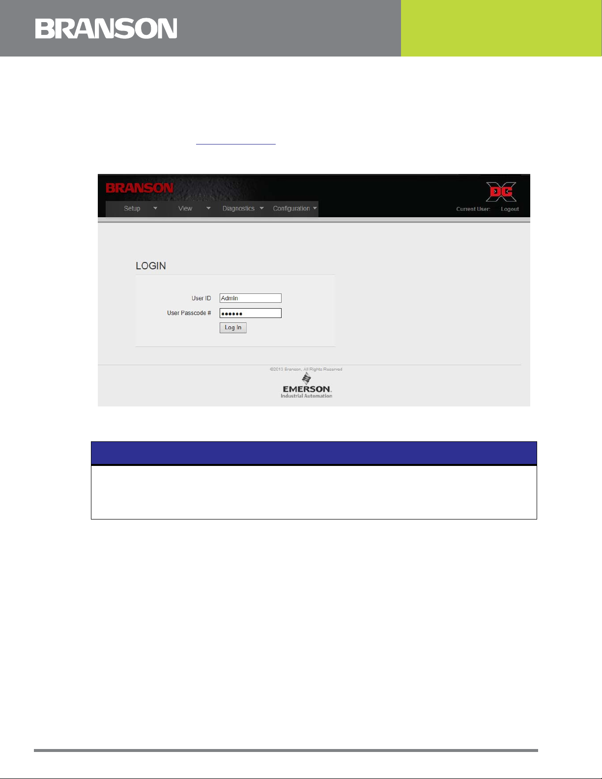
4.2 Login
When connection is established with the DCX Web Page Interface, the Login page will
display. Enter a unique User ID and a numeric password. The User ID is alphanumeric an
up to 12 characters long. The passcode is numeric only and is 9 digits long. This User ID/
Passcode combination allows for restricting access as specified on the Configuration >
Passcode menu. See
Figure 4.2 Login
4.6.4 Passcodes for more information.
NOTICE
Initial Login
• User ID: Admin
User Passcode #: 999999
28 100-412-203 REV. 04

4.3 Setup Menu
Use this menu to set weld parameters, amplitude, save/recall presets, limits and cutoffs,
seek options, and power-up actions. Use the command buttons on the bottom to save
settings, cancel changes, or to restore to factory default settings.
4.3.1 Weld
Use this menu to set weld parameters.
Figure 4.3 Weld
Table 4.2 Weld Options
Name Description
MODE
Continuous Weld mode changes to Continuous after pressing save button.
Time Weld mode changes to Time after pressing save button.
Weld mode changes to Energy after pressing save button.
Energy
Peak Power Weld mode changes to Peak Power after pressing save button.
100-412-203 REV. 04 29
NOTICE
Values above 1000.0 J will be rounded up.

Table 4.2 Weld Options
Name Description
Ground Detect Weld mode changes to Ground Detect after pressing save button.
AFTERBURST
Delay Sets the delay time in seconds if afterburst is turned on.
Time Sets the afterburst time if afterburst is turned on.
FREQUENCY
Digital Tune Starting frequency set from horn signature or manually entered.
Internal Offset
Sets the frequency offset from the Web P age as either a positiv e or
negative value offset from digital tune.
External Offset Frequency is set from 26-pin user I/O connector or fieldbus.
End of Weld
Store
Clear Memory
with Reset
Clear Memory
before Seek
Set with Horn
Scan
Select to save the frequency at the end of the weld as the starting
frequency for the following weld.
Select to clear memory with reset. Memory offset will be set to 0
when a Reset is applied. Reset can come from external I/O, front
panel or web page interface (seek or horn scan).
Select to clear memory before seek. Memory offset will be set to 0
before Seek is applied.
Select to set Digital Tune frequency with a successfully completed
horn scan.
OTHER
Energy Brake
Enables energy brake. When enables, the power supply has some
time to reduce the amplitude before the sonics are shut off.
Hold Time Enter hold time value if operating in cycle mode.
30 100-412-203 REV. 04

4.3.2 Amplitude
Use this menu to set amplitude parameters.
Figure 4.4 Amplitude
Table 4.3 Amplitude Options
Name Description
WELD AMPLITUDE
Fixed @ Amplitude 1 Select for constant amplitude.
External Analog In
Step @ Time (s) Set the step time interval in seconds.
Step @ Energy (J)
Step @ Power (%) Set the step power interval in percentage.
Step @ External
Amplitude 1 (%) Set the amplitude in percentage.
Amplitude 2 (%) Set the amplitude in percentage.
AMPLITUDE RAMP
When selected, Weld Amplitude text box inputs will be disabled.
Set the amplitude externally using the user I/O connector.
Set the step energy in joules.
NOTICE
Values above 1000.0 J will be rounded up.
When selected, it allows a digital input to choose between
Amplitude 1 and Amplitude 2.
Ramp Time Sets time for amplitude ramp from 0 to 100% amplitude.
100-412-203 REV. 04 31

Table 4.3 Amplitude Options
Name Description
TEST AMPLITUDE
Same as Amplitude 1
or External Analog in
Test Amplitude (%) Manually set the value for the test amplitude.
OTHER AMPLITUDE
Scrub Amplitude (%)
Afterburst Amplitude
(%)
When selected, test amplitude value will match the value set in
amplitude 1 or External Analog In, depending on which one is
selected in Weld Amplitude container.
Sets the scrub amplitude in percentage when ground detect
mode is selected.
Sets the afterburst amplitude in percentage when afterburst
mode is selected.
4.3.3 Save/Recall Preset
Use this menu to save and recall stored presets.
Figure 4.5 Save/Recall Presets
Table 4.4 Save/Recall Preset Options
Name Description
WELD PRESETS
Save
Recall Click to recall the highlighted preset.
Select Horn Preset
Clear Memory
Counter
32 100-412-203 REV. 04
Click to save current settings. You can save the preset with an
alphanumeric description up to 24 characters.
Click to select one of the 16 available horn presets, including a
default option.
Click to clear the memory frequency for selected horn in Selected
Horn Preset menu.

Table 4.4 Save/Recall Preset Options
Name Description
Restore Defaults Click to restore highlighted preset to default parameters.
Reset Cycle Run
Counter
4.3.4 Limit/Cutoff
Use this menu to set limits and cutoffs.
Figure 4.6 Limit/Cutoff
Click to reset the cycle run counter for highlighted preset.
Table 4.5 Limit/Cutoff Options
Name Description
LIMITS
Off Select to disable limits.
100-412-203 REV. 04 33

Table 4.5 Limit/Cutoff Options
Name Description
If selected, you can set minus and plus limits for time, energy and peak
power in seconds, joules, and percentage respectively.
On
NOTICE
For Energy (J), values above 1000.0 J will be rounded up.
CUTOFFS
Off Select to disable cutoffs.
If selected, you can set the cutoff for time, energy and peak power in
seconds, joules, and percentage respectively. You can set cutoffs for Custom
On
Input1 and Custom Input2 in voltage, which are custom analog inputs or
fieldbus. User can also set cut off for Frequency High and Frequency Low in
Hertz as an offset to the midband.
Restore
Defaults
Click to restore default limits and cutoff settings.
4.3.5 Seek/Power Up
Use this menu to set seek options and power up actions.
Figure 4.7 Seek/Power Up
Table 4.6 Seek/Power Up Options
Name Description
SEEK
Seek Time (s) Sets the seek time in seconds.
Seek Ramp (s) Sets the seek ramp time in seconds.
Frequency Offset (Hz) Sets the frequency offset in Hertz.
POWER UP
Off Select to disable seek and scan during power up.
34 100-412-203 REV. 04

Table 4.6 Seek/Power Up Options
Name Description
Seek Select to enable seek during power up.
Scan Select to enable scan during power up.
Restore Defaults Click to restore default seek and power up settings.
100-412-203 REV. 04 35

4.4 View Menu
Use this menu to view information and log files about your DCX Power Supply. Have the
information on this screen available when calling Branson for troubleshooting help.
4.4.1 System Info
Use this menu to view information about your DCX Power Supply. Have the information on
this screen available when calling Branson for troubleshooting help.
Figure 4.8 System Info
Table 4.7 System Info Options
Name Description
SYSTEM INFORMATION
System WC
Display
DCP
Web Page This field lists the current version of the web page.
Boot Loader DCP
Boot Loader WC
Controller This field lists the version number for the FPGA software.
Display the power supply type (A or F) and the serial number of the
unit.
This will list either “OK” if a display is found or “Not Detected” if no
display is found.
This field lists the power level and frequency as reported by the DCP
board. If the DCP board is not detected at power up then “Not
Detected” is shown.
This field lists the version number and CRC for the boot loader
software that resides on the DCP board.
This field lists version number and CRC for the boot loader software
that resides on the WC board.
36 100-412-203 REV. 04

Table 4.7 System Info Options
Name Description
Actuator Detect
Fieldbus
4.4.2 Alarm Log
Use this screen to view the DCX Power Supply alarm history. The alarms can be sorted by
alarm number or alarm type. Alarms can be exported to an Excel file.
NOTICE
Only the last 100 alarms are stored in memory.
Figure 4.9 Alarm Log
This field lists “Yes” if the actuator connected pin is 24 V at power
up. Otherwise, it will list “No”.
If the unit is programmed as a Fieldbus unit, this field will show the
type of Fieldbus found or “Not Detected” if a Fieldbus was not
found. Otherwise, this field will not be shown.
Table 4.8 Alarm Log Options
Name Description
Alarm #
100-412-203 REV. 04 37
A unique alarm identification number. This number will
reset to zero if the alarm log is cleared.

Table 4.8 Alarm Log Options
Name Description
The DCX AF units feature an integrated real time clock.
Date & Time
Alarm date and time reflect the real date and time as set
on the 4.6.1 System page.
Cycle Num Displays the cycle number.
Alarm Displays the alarm description.
Alarm Code Displays the alarm code.
ALARM DESCRIPTIONS
Frequency - High Seek
Limit
Frequency - Low Seek
Limit
Frequency - High Weld
Limit
Frequency - Low Weld
Limit
Frequency reached high end limit: 20 kHz: 20.450 kHz,
30 kHz: 30.750 kHz, 40 kHz: 40.900 kHz.
Frequency reached low end limit: 20 kHz: 19.450 kHz,
30 kHz: 29.250 kHz, 40 kHz: 38.900 kHz.
Frequency reached high end limit: 20 kHz: 20.450 kHz,
30 kHz: 30.750 kHz, 40 kHz: 40.900 kHz.
Frequency reached low end limit: 20 kHz: 19.450 kHz,
30 kHz: 29.250 kHz, 40 kHz: 38.900 kHz.
Overload - Current RF current peak limit reached.
Frequency reached high or low end limit. Frequency
Overload - Frequency
numbers are the same as above depending on the system
(20 kHz, 30 kHz, 40 kHz).
Overload - Power Limit Power supply reached 115% rated power.
Overload - Temperature IGBT heat sink temperature limit is reached.
Overload - Voltage RF voltage peak limit reached.
Phase Limit Time Error
When power supply out of tune phase limit error is reached
after 500ms (default).
ALARM LOG
Clear Log Click to clear the alarm log.
Export to Excel Click to export the data to an Excel sheet.
38 100-412-203 REV. 04
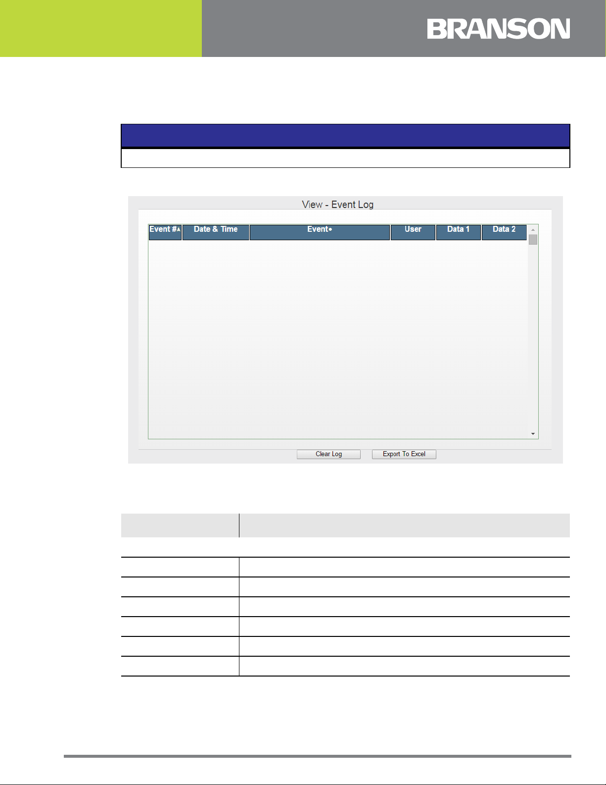
4.4.3 Event Log
Use this screen to view the DCX Power Supply event history. The events can be sorted by
event number, date/time or event type. Events can be exported to an Excel file.
NOTICE
Only the last 500 events are stored in memory.
Figure 4.10Event Log
Table 4.9 Event Log Options
Name Description
EVENT LOG
Event # Event number.
Date & Time Date and time when event has logged.
Event Event description.
User User ID at the time of event.
Clear Log Click to clear the event log.
Export to Excel Click to export the data to an Excel sheet.
100-412-203 REV. 04 39

4.4.4 History
Use this screen to view the DCX Power Supply weld history. The weld history can be sorted
by cycle number or date/time. Weld history can be exported to an Excel file.
NOTICE
Only the last 50 weld history entries are stored in memory.
Figure 4.11History
Table 4.10 History
DATA
Cycle # Date & Time
Weld Mode Weld Time
Weld Energy Peak Power
Amplitude 1 Amplitude 2
Preset # Start Frequency
Stop Frequency Frequency Change
Alarm Code CustomIn1
CustomIn2 Cycle Time
40 100-412-203 REV. 04

Table 4.11 History Options
Name Description
HISTORY
Clear History Click to clear the weld history.
Export to Excel Click to export the data to an Excel sheet.
100-412-203 REV. 04 41

4.4.5 Weld Graphs
Use this menu to view and export the weld graph. The weld graph is provided with 6
available parameters: Phase, Current, Amplitude, Power, PWM Amplitude, and Frequency.
Each parameter has a checkbox to the left of its name. Only checked parameters will be
displayed. While in this menu, if the W eld is being run from external I/O or the front panel
interface, the graph can be also displayed on the screen by using the “Update Graph”
button.
Figure 4.12Weld Graphs
Table 4.12 Weld Graphs Options
Name Description
WELD GRAPHS
Click to get the value of all the parameter and draw the graph
Update Graph
Export Graph Data Click to export the data to an Excel sheet.
Redraw Graph
Set Default
42 100-412-203 REV. 04
for Phase, Current, Amplitude, Power, and Frequency
parameters vs Time on the Y axis.
Click to redraw the same graph with those parameters which
are checked with the Time parameter on Y axis.
Click to restore the settings on the “Draw from”, “Graph
Selection”, “X Value” and “Y Value” fields.

Table 4.12 Weld Graphs Options
Name Description
Click to get the value for any parameter for any time by setting
Update Value
the parameter in the drop down list for a graph selection field
and by setting value in the X value and Y value field.
100-412-203 REV. 04 43
4.5 Diagnostics Menu
Use this menu to test your DCX AF Power Supply.
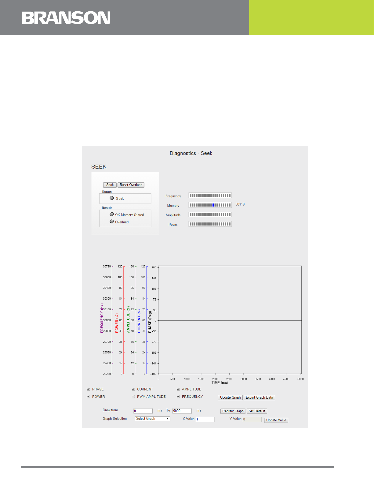
4.5.1 Seek
This feature allows you to capture seek data which you can both view and export. The
Weld Data Graph is provided with 6 available parameters: Phase, Current, Amplitude,
Power, PWM Amplitude, and Frequency. Each parameter has a check box to the left of its
name. Only checked parameters will be displayed. While in this menu, if the Weld is being
run from external I/O or the front panel interface, the graph can be also displayed on the
screen by using the “Update Graph” button.
Figure 4.13Seek
44 100-412-203 REV. 04

Table 4.13 Seek Options
Name Description
SEEK
Seek Click to perform a seek cycle.
Reset Overload Click to reset an overload condition.
Seek
OK - Memory
Stored
Overload
Indicates that the power supply is running at 10% amplitude for the
purpose of finding the ultrasonic stack resonant frequency.
Indicates that the horn operating frequency was stored in the DCX
Power Supply memory.
Indicates that test resulted in an overload and the memory has
been cleared.
Frequency Monitors the seek operating frequency.
Memory Displays the frequency stored in the DCX Power Supply memory.
Amplitude Displays the percentage of stack amplitude.
Power Displays the percentage of power output.
Update Graph Click to draw the graph of the last seek data.
Export Graph
Data
Redraw Graph
Draw from...
to...
Click to export the Weld Graph data to CSV file.
Click to redraw the same graph with those parameters which are
checked with the Time parameter on Y axis.
Select the “from” and “to” time values to zoom into the desired
graph region.
Graph Selection
Select a parameter and enter a particular X time value to obtain the
corresponding Y value at that particular time.
Update Value Click to update the Y value for the given graph selection.
Set Default
Click to return start time, end time and graph selection to default
settings.
Enter comments to be added at the top of exported data in CSV file.
User Comment
Box
NOTICE
This option is only available after selecting export.
100-412-203 REV. 04 45

4.5.2 Horn Signature
Use this menu to diagnose your ultrasonic horn. When performing a horn scan, ideally,
there will be only one parallel resonant frequency. The Horn Signature Graph is provided
with 3 available parameters: Phase, Current, and Amplitude. The Horn Signature Graph
can be both viewed and exported.
Each parameter has a checkbox to the left of its name. Only checked parameters will be
displayed.
Figure 4.14Horn Signature
46 100-412-203 REV. 04

Table 4.14 Horn Signature Options
Name Description
HORN SIGNATURE
Start Horn Scan Click to initiate the horn scan.
Abort Horn Scan Click to abort the horn scan.
Status Indicates the horn scan progress.
Result
Indicates if the horn scan passed, failed, or if the operation was
aborted.
Displays the parallel resonant frequencies of the ultrasonic
horn. The parallel resonant frequency is the operating frequency
of the ultrasonic stack.
Parallel Resonant
Points
NOTICE
If multiple parallel frequencies are found, they will all be listed.
The frequency at which the ultrasonic stack is running will be
displayed in blue.
Series Resonant
Points
Displays the series resonant frequencies of the ultrasonic horn.
Update Graph Click to draw the graph of the last horn scan.
Export Graph Data
Redraw Graph
Draw from... to...
Graph Selection
Click to export the scan graph data with scan settings to CSV
file.
Click to redraw the same graph with those parameters which
are checked with the Time parameter on Y axis.
Select the “from” and “to” time values to zoom into the desired
graph region.
Select a parameter and enter a particular X time value to obtain
the corresponding Y value at that particular time.
Update Value Click to update the Y value.
Set Default
User Comment Box
Click to return the sample rate, start time, end time and graph
selection to default settings.
Enter comments to be added at the top of exported data in CSV
file.
100-412-203 REV. 04 47

4.5.3 User I/O
Use this menu to monitor and control the DCX Power Supply digital and analog I/O. For
user I/O configuration instructions see 4.5.3 User I/O.
NOTICE
The assigned power supply functions will not be performed by the power supply, only
the signals levels can be controlled and monitored while in this menu.
Figure 4.15User I/O
Table 4.15 User I/O Options
Name Description
USER I/O
Digital Inputs A LED icon will light when that corresponding input is active.
Analog Inputs
Digital Outputs
48 100-412-203 REV. 04
The analog inputs have text boxes that display the actual
voltage being read from the corresponding pins.
Check the digital outputs before selecting Refresh Outputs to
designate which digital outputs they wish to see active.

Table 4.15 User I/O Options
Name Description
Analog Outputs
The analog outputs allows to input a voltage value wanted to
see on the output pin.
These boxes display the information to the user that was
Activity Definition
defined on the I/O Configuration page about how each pin is
defined as far as active high versus active low.
Pressing the Refresh Outputs buttons will read all the check
Refresh Outputs
boxes for digital outputs and all the input text boxes for
analog outputs and output the appropriate values to the
connector.
The stop button will be grayed out until Refresh Outputs is
Stop
pressed. Pressing stop will cause the outputs to revert to the
actual state of the outputs and Refresh Outputs shall become
enabled.
Fan On/Off Click to turn on/off the fan.
100-412-203 REV. 04 49

4.5.4 Fieldbus
Use this menu to check Fieldbus information. See DCX AF Series Power Supply Instruction
Manual for setup and operation.
Figure 4.16Fieldbus (EtherNet/IP)
Table 4.16 Fieldbus Options
Name Description
FIELDBUS INFO
The Fieldbus info box will display all relative information
Fieldbus Info
Slave Status - Offline
Slave Status - Stop
Slave Status - Idle Shows whether the Fieldbus device is in the idle state.
Slave Status - Operate Shows whether the Fieldbus card is in data exchange.
COMMUNICATION STATE
50 100-412-203 REV. 04
regarding high level diagnostic data. Things such as slave
address, on/off and whether an error is present or not are
viewed here.
The Fieldbus card is offline when it does not have a valid
configuration.
The Fieldbus device was stopped by the application program
or it changed to the Stop state because of a bus error.

Table 4.16 Fieldbus Options
Name Description
Ready
This bit is set by the Slave automatically, when the
parameters sent by the master are containing wrong or
insufficient data.
Running
Bus On
Configuration Locked
This shows whether the Fieldbus card has been configured
correctly.
This shows whether the Fieldbus card and WC board are
communicating.
Shows whether the Fieldbus configuration is locked, to avoid
the configuration data are typed over.
This bit is set by the Slave automatically, when the
Parameter Fault
parameters sent by the master are containing wrong or
insufficient data.
Configuration Fault
At startup, if configuration of the master does not match that
of the slave, this bit is set.
CONTROL AND STATUS LEDS
Control Word Status
Word
Control and status LEDs show the binary signals exchange
between master and slave. Green = 1, Gray = 0.
100-412-203 REV. 04 51

4.5.5 Fieldbus Test Menu
Use this menu to perform a Fieldbus test.
4.5.5.1EtherNet/IP
Figure 4.17Fieldbus Test (EtherNet/IP)
Press the Update button to get the Control and Status (STW and ZSW) binary signals
currently being exchanged with the EtherNet/IP master.
Pressing the Update button will also display the last explicit message received from the
master and the reply of the same sent by the WC. CIP Status tells the success or failure of
the processed Explicit message.
52 100-412-203 REV. 04

4.5.5.2PROFIBUS DP
Figure 4.18Fieldbus Test (PROFIBUS DP)
Press the Update button to display the last parameter number accessed by the PROFIBUS
master through the PKW channel and the answer replied by the WC.
100-412-203 REV. 04 53

4.6 Configuration Menu
4.6.1 System
Use this menu to set the date/time of your DCX Power Supply and backup/restore the
system.
Figure 4.19System
Table 4.17 System Options
Name Description
CONFIGURE SYSTEM
System Date & Time
Select Date Format
Select Time Format
Get Time From PC
Backup System
This label updates its value every second from the power
supply with system date and time.
Select the date format. Available formats are MM-DD-YYYY
and DD-MM-YYYY.
Select the time format. Available formats are 12 Hours and 24
Hours.
The time and date will be loaded from the PC. It will be
displayed in the format selected above.
NOTICE
You must click save to confirm the change.
This button will bring up a Windows pop up box to select a
location to save a binary file that contains the contents of
system memory.
54 100-412-203 REV. 04

Table 4.17 System Options
Name Description
Browse
Copy System
Selecting Browse will bring up a Windows pop up for selecting
the location of a backup system file (.cfg) to import. Once the
file has been browsed to, either Copy System or Restore
System can be selected.
Click to copy the system settings of another DCX unit using a
backup system file (.cfg). See 4.6.1.1 Copy System and
Restore System Data for more information.
NOTICE
The backup system file (.cgi) must be from another DCX
system using the same software version. See 4.4.1 System
Info to see the software version.
Click to restore the system with a previously saved backup
system file (.cfg).
Restore System
NOTICE
The backup system file (.cgi) must be from another DCX
system using the same software version. See 4.4.1 System
Info to see the software version.
Load Preset On Start check box will allow the user to turn on
Load Preset On Start
or off automatic loading of preset regardless of the preset
signal on the I/O.
This option configures the “STD-Status” digital output to show
the status of the power supply. The digital output can be
connected to an external device, for example, an external
beeper. When this option is enabled, the user must check
either “Trigger – 1” and/or “Alarm – 3”.
External Status
Enabled
If Trigger - 1 is checked, there will be 1 digital output pulse on
the STD-Status output pin and 0.5 second beep will occur
when trigger is received.
If Alarm - 3 is checked, then when an alarm occurs (e.g.
overload alarm), 3 pulses will be output on the Status pin to
indicate an alarm occurred. Beeps 0.5 seconds on, 0.5
seconds off long are in between each beep.
Restore Defaults Click to restore system configuration default settings.
100-412-203 REV. 04 55

4.6.1.1Copy System and Restore System Data
The following data will be overwritten.
Table 4.18 Copy System and Restore System Data
System Setting
Presets Yes Yes
Horn Presets Yes Yes
Alarm Configuration Yes Yes
Passcode Configuration Yes Yes
User I/O Configuration Yes Yes
Even Log Yes No
Alarm Log Yes No
Weld History Yes No
System Configuration
IP Address
PROFIBUS and EtherNet/IP Address
MAC Address No No
Power Supply Frequency and Power Level No No
Total Alarm Counter Yes Yes
Overwritten
by Restore
Yes No
Overwritten
by Copy
Total Cycle Counter Yes Yes
Hours of Sonics Yes Yes
Power on Hours Yes Yes
Manufacturing Cycle of Parameters and Results Yes Yes
Advanced R&D Parameters Yes Yes
Memory Frequencies
NOTICE
A soft reset of the system is performed after a restore
or copy. Memory frequencies will be adjusted to
midband if they don’t fall within the minimum/
maximum range of the power supply frequency.
Alarm Group Counters Yes Yes
Serial Number Yes No
Control Level Yes No
Yes Yes
56 100-412-203 REV. 04

4.6.2 User I/O
Use this menu to configure the DCX Power Supply I/O according to your specific
interfacing needs. Use the command buttons on the bottom to save settings, cancel
changes, or to restore to factory default settings.
NOTICE
See DCX equipment manual for a list of I/O.
Figure 4.20User I/O
100-412-203 REV. 04 57

4.6.3 Communication
Use this menu to setup the DCX Power Supply’s network settings. The DCX P ower Supply’ s
default IP setting is Static IP with the address shown in the figure below.
Figure 4.21Communication (EtherNet/IP)
Table 4.19 Communication Options
Name Description
IP SETUP
Select this option to manually assign an IP address to the DCX
Static IP
IP Address The IP address assigned to the DCX Power Supply.
Subnet Mask
Gateway
MAC Address Displays the MAC address assigned to the DCX Power Supply.
DHCP Server
Enabled
Power Supply. The DCX Power Supply will alert if an invalid IP
address setting is entered.
The mask used to determine to what subnet the DCX Power Supply’s
address belongs to.
The gateway address assigned to the network for communication
with other computers or networks.
Select this option to have DCX Power Supply assign IP addresses to
any devices connected to it. This facilitates connecting a computer
or laptop point to point (P2P) with the DCX Power Supply.
NOTICE
Connecting a DCX Power Supply with DHCP server enabled to a
network which already has a device working as a DHCP server will
cause connectivity problems.
Select this option to have the DCX Power Supply automatically
DHCP
FIELDBUS
58 100-412-203 REV. 04
request an IP address from a DCHP Server. The IP address will be
grayed out.

Table 4.19 Communication Options
Name Description
The Fieldbus section will only be displayed if the power supply
Fieldbus
version is a DCX F. If Profibus is enabled, then only the Profibus
Address will be displayed. Likewise if it is EtherNet/IP enabled, then
everything but the Profibus Address will be displayed.
NOTICE
All changes on this menu take effect on the next power-up.
At any time you may determine the DCX Power Supply’s IP address by going through the
associated registers using the front panel LCD. A Cold Start can also be performed to take
your power supply back to it’s factory default IP address. For details on navigating the
DCX registers or performing a Cold Start, consult your power supply manual.
NOTICE
Beware that other settings will also be reset to their defaults when a Cold Start is
executed.
100-412-203 REV. 04 59

4.6.4 Passcodes
Use this menu to manage users, passcodes and privileges of each user.
Figure 4.22Passcodes
Table 4.20 Passcodes Options
Name Description
PASSCODES
The user ID is an alphanumeric character string of up to 12
User ID
Passcode
Privilege Click to change user privileges.
60 100-412-203 REV. 04
characters. This is the text that will appear in the logs under the
User column.
The passcode is numeric only and up to 9 characters long. The
passcode is what the user enters along with their User ID when he
logs into the web page. An admin can see everyone's passcode.

Table 4.20 Passcodes Options
Name Description
Only an admin can check or uncheck this box. If passcodes are
required, at least a user must be logged in through the web page
before any changes can be made through the web page. Changes
can always be made through the Fieldbus, if connected. If
unchecked, the User IDs will still display in the logs, but if no User
Passcodes
Required
ID is associated with a passcode, then the passcode is used for the
log.
To access as an admin, use the following information at login:
User ID: Admin
User Passcode #: 999999
100-412-203 REV. 04 61

4.6.5 Alarms
Use this menu to configure the alarms.
Figure 4.23Alarms
Table 4.21 Alarm Options
Name Description
ALARMS
Reset Required
Log Alarm
General Alarm
Custom Alarm
Output
Cycle Counter
This option determines if the alarm is latched or not. Latched
alarms require a reset before another cycle can start.
This option determines whether or not the alarm is entered into a
log. Communication and Hardware alarms will be logged into the
event log.
If selected, this alarm group will activate the general alarm
output, if defined.
If selected, this alarm group will activate the Custom Alarm
output, if defined.
If selected, the cycle will count toward both the preset counter. If
deselected, the preset counter will not count.
62 100-412-203 REV. 04
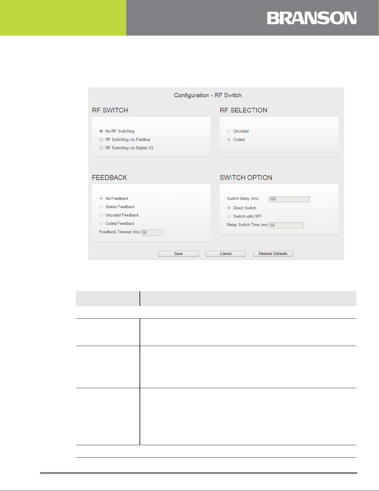
4.6.6 RF Switch
Use this menu to configure the RF Switch options. RF switches are external to the DCX
and control RF output to a stack.
Figure 4.24RF Switch
Table 4.22 RF Switch Options
Name Description
RF SWITCH
If selected, there will be no RF switching using either the Fieldbus
No RF Switching
RF Switching Via
Fieldbus
RF Switching Via
Digital I/O
RF SELECTION
or digital I/O. If this option is selected the rest of the web page is
grayed out and unavailable.
When a preset is recalled through the Fieldbus, after the
appropriate delay a response will be sent back to the PLC with the
stack number. It's up to the PLC to then send the proper command
to the RF switch to select the correct output. This option will not be
available unless the system is defined as an Fieldbus unit.
When a preset is recalled via the user-defined I/O, after the
appropriate delay the user defined outputs will be set to the correct
value to select the correct stack as defined by the recalled preset.
There is a limit of seven stacks that can be supported with digital I/
O. If a stack number greater than 7 is requested an E707 alarm will
be created. Feedback, if enabled, can only occur as a coded value
(4 inputs) or a single input to indicate the selection was made.
100-412-203 REV. 04 63

Table 4.22 RF Switch Options
Name Description
RF Selection will decide the input format for RF selection bits. It will
RF Selection
only be applicable in case of RF switching through IO. User can
decide the coded or uncoded format for RF selection input.
FEEDBACK
This option assumes the correct stack has been selected. No error
No Feedback
checking will be done. The Relay Switch Time must elapse before
sonics can be turned on.
Status Feedback
This option requires a single input pin. The pin must go active
within the Relay Switch Time or an alarm (E705) will be created.
Uncoded
Feedback
This option requires four input pins. The stack number uncoded on
these pins must go active within the Relay Switch Time or an
alarm(E705) will be created.
This option requires four input pins. The stack number encoded in
Coded Feedback
binary must be on these pins at the end of the Relay Switch Time
or an alarm (E705) will be created.
Feedback Timeout
(ms)
If feedback is selected, then this will be the maximum time that
the system will wait before creating an RF Switch Feedback Failure
(E705) alarm.
SWITCH OPTION
Switch Delay
(ms)
Direct Switch
The system will wait this many milliseconds after sonics turns off
before the system will return to the Ready state. RF relays can only
be switched when the system is Ready.
Direct switch changes the relays from one setting to the new
setting.
Switch With Off This setting allows an “OFF” state in between each stack setting.
Relay Switch Time
(ms)
Switch time is the duration of the “OFF” status.
64 100-412-203 REV. 04

Appendix A: Ultrasonic Welding
A.1 Resonance . . . . . . . . . . . . . . . . . . . . . . . . . . . . . . . . . . . . . . . . . . . . . 66
A.2 The Principle and the Components of Ultrasonic Welding . . . . . . . . . 67
A.3 Resonance Analysis . . . . . . . . . . . . . . . . . . . . . . . . . . . . . . . . . . . . . . 70
A.4 Graphics of a Weld . . . . . . . . . . . . . . . . . . . . . . . . . . . . . . . . . . . . . . . 74
100-412-203 REV. 04 65

A.1 Resonance
Every solid body has its natural resonance. This is determined by the material it is made
of and its total mass.
If, for example, a spanner falls on the ground, the typical metallic sound is generated. If
we would measure the tone pitch, we would have determined the natural resonance of the
spanner. Another classic example is the tuning fork. It is designed in a manner that it
exactly vibrates at 440 Hz (philharmonic pitch A).
These are examples for resonance in the audible range (approx. 40 Hz to 16 kHz).
Starting from a frequency of 20 kHz this is referred to as ultrasonics. Also, any
combination of converter, booster, and has its natural resonance.
The aim is to utilize this resonance in order to achieve a maximum effect at lowest
possible energy consumption. This is the case if - to ease the explanation - the vibrating
frequency fed in corresponds to the resonant frequency of the acoustic stack. In this
respect, it is important that an acoustic stack has two resonance points: a serial and a
parallel one. The parallel resonance point is the decisive one.
66 100-412-203 REV. 04

A.2 The Principle and the Components of Ultrasonic
Welding
A.2.1 The Principle
The tool vibrating at ultrasonic frequency is pressed onto the plastic parts to be welded.
The plastic material has the propensity to absorb the vibrations fed in, which results in
heating up of the joints to the melting point. The mechanical pressure exerted generates a
flow of the plasticized material between the two parts.
After cooling down, a virtually homogeneous joint is the result.
A.2.2 The Components
Figure A.1 The components of an ultrasonic welding system
Table A.1 The components of an Ultrasonic Welding System
Item Description
1 Ultrasonic Power Supply
2 Converter
3 Booster
4 Horn
5 Acoustic Stack
The power supply (1) transforms the energy supplied at 50/60 Hz from the mains to an
ultrasonic frequency of 20 kHz, 30 kHz or 40 kHz.
The high-frequency electrical oscillations of the power supply are transformed by the
converter (2) via a piezoelectric oscillator into mechanical vibrations of the same
frequency, i. e. into mechanical vibrations at 20 kHz, 30 kHz or 40 kHz.
100-412-203 REV. 04 67

The mechanical vibrations must be transferred to the plastic part to be welded via an
acoustic tool combination of booster (3) and horn (4). The booster amplifies the amplitude
of the mechanical vibration (amplification factor K1).
The Booster
The booster is a one half wavelength long resonant section made of aluminum or titanium.
It is mounted between the converter and the horn, and modifies the amplitude of vibration
applied to the horn. The amplitude is amplified according to the energy conservation law.
To amplify the amplitude of the vibration the cross-sectional area of the booster is varied.
As the vibratory energy must remain constant over the whole length of the booster
(energy conservation law) the amplitude is amplified proportional to the area ratio. This
process can be illustrated by an undamped spring-mass system. When the spring-mass
system is excited it will emerge that the short thick spring has a shorter elongation
compared to the thin long spring although both spring oscillate at the same frequency. For
the ratio the following formula applies:
Where:
• A
= Input Amplitude
e
= Output Amplitude
A
e Ve Me
F = = =
A
a Va Ma
• A
a
= Input Oscillating Velocity
• V
e
= Output Oscillating Velocity
• V
a
= Input Mass
• M
e
• M
= Output Mass
a
Figure A.2 Amplitude Transformation Via the Booster
Nodal Point
The Horn
The horn (also: welding tool) transmits the mechanical vibrations transformed by the
converter and amplified by the booster to the plastic part.
Not only the booster but also the horn can amplify the amplitude (amplification factor K2).
For calculation of the amplitude ratios almost the same approach applies as for boosters.
68 100-412-203 REV. 04

Figure A.3 Commonly used horn shapes
Table A.2 Commonly used horn shapes
Item Description
1 Rectangular horn
2 Catanoidal horn
3 Exponential horn
4 Step horn
The combination of converter, booster and horn is referred to as acoustic stack.
The prerequisite for a transfer of ultrasonic vibrations to the workpiece without losses is a
transfer of acoustic energy between the individual components of acoustic stack with the
lowest possible amount of reflection. The quality of the transfer essentially depends on the
assembly of the individual components.
100-412-203 REV. 04 69
A.3 Resonance Analysis
The acoustic stack is an acoustic precision tool that, like any other tool, is subject to wear.
Depending on load, maintenance, and conditioning of this tool, defects may occur: the
threaded joints between the components may become loose, deposit may build up at the
mating surfaces, or cracks may be generated in the horn. The result: the resonant
properties of the acoustic stack are impaired. The quality of the weld is reduced, and the
power supply frequently switches to overload state.
For this reason, the DCX W eb P age Interface provides the possibilit y to “scan” the acoustic
stack. This means that ultrasonics is applied, with the ultrasonics frequency going through
a preset frequency range, e. g. 19500 Hz to 20500 Hz. In the course of this, taking preset
values, e. g. for amplitude and step width, into account, important characteristics like
output current and phase are recorded and shown graphically on the display.
The curves of phase, amplitude, and current over the frequency indicate the points of
serial resonance and parallel resonance of the acoustic stack. The parallel resonance
relevant for operation lies at the point at which the algebraic sign of the phase changes
the second time.
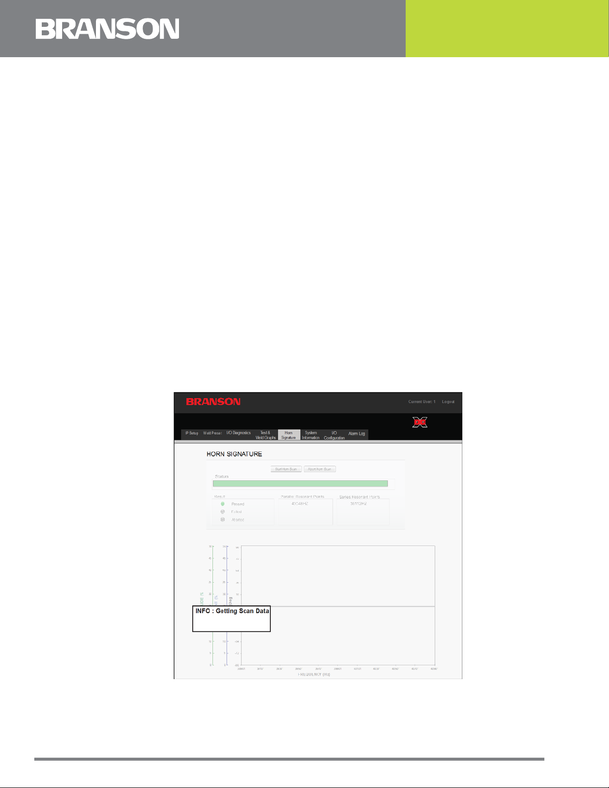
A.3.1 Getting a Horn Scan Data
Click the Start Horn Scan button to initiate the horn scan, the progress of the Scan is
displayed on progress bar. When the Scan is completed, the Scan data is imported. During
import a message appears as shown below. Message is automatically cleared when all
data is received for graph.
Figure A.4 Getting Scan Data
70 100-412-203 REV. 04

A scan is an automatic frequency seek. The values determined are stored and graphically
displayed. The values inform about the resonance properties of the system. When you
compare the curve with other curves you can draw conclusions with respect to the
functioning and the acoustic properties of the acoustic stack.
In the course of the scan, ultrasonics are applied to the acoustic stack (converter/booster/
horn) without load. The stack freely vibrates in the air, starting with a start frequency that
is continually increased up to the adjusted end frequency.
Figure A.5 Graphics of a scan
At the point of resonance, the current falls, the amplitude is at the maximum value, and
the phase changes its sign.
NOTICE
If multiple parallel frequencies are found, they will all be listed under Parallel Resonant
Points. The frequency at which the acoustic stack is running will be shown in blue.
100-412-203 REV. 04 71
A.3.2 Scan Horn Error Analysis
On the following pages, typical sources of error are shown.
Compare your system's curves with these examples to identify some of the possible
problems you may encounter.
Figure A.6 Horn Scan, Possible Defective Converter
72 100-412-203 REV. 04

Figure A.7 Horn Scan, Open RF Cable
100-412-203 REV. 04 73
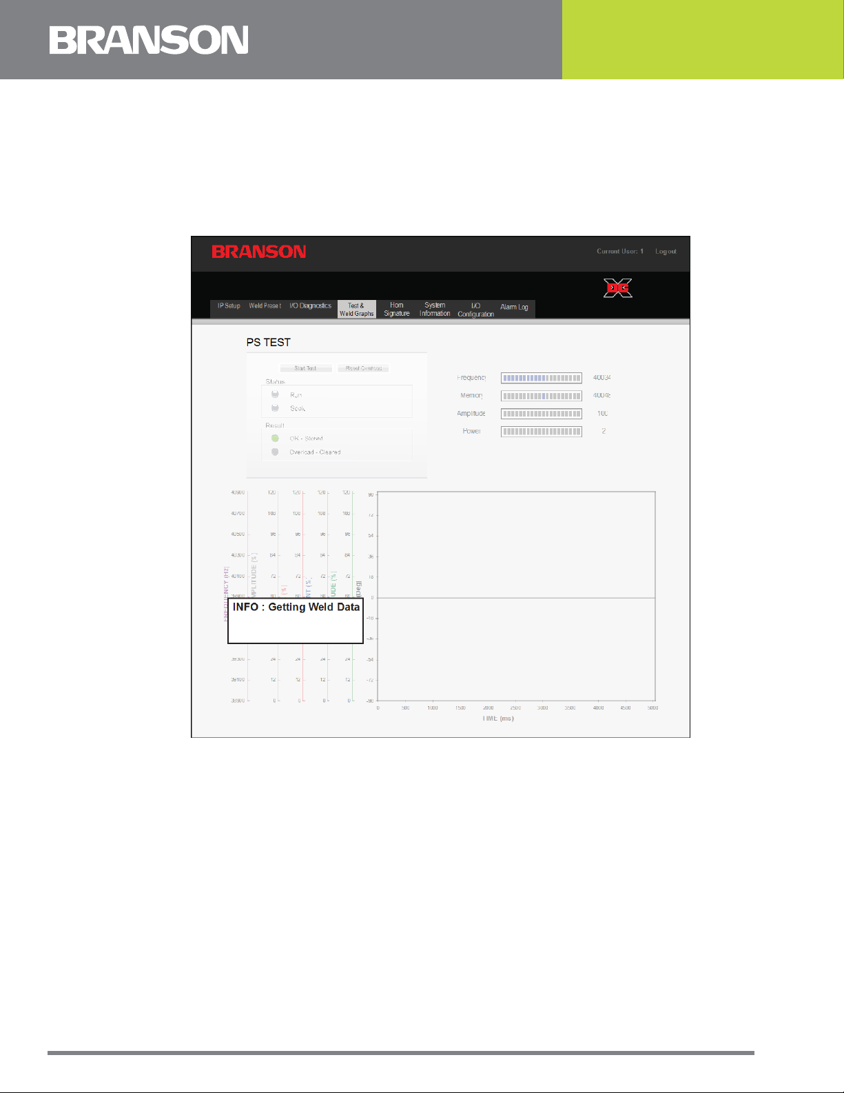
A.4 Graphics of a Weld
Weld Values can also be displayed as curves.
When you click on the Update Graph button, the Weld data is imported. While data is
being transferred a message is appears, as shown below. Message is automatically cleared
when all data is received for graph.
Figure A.8 Getting Weld Data
74 100-412-203 REV. 04

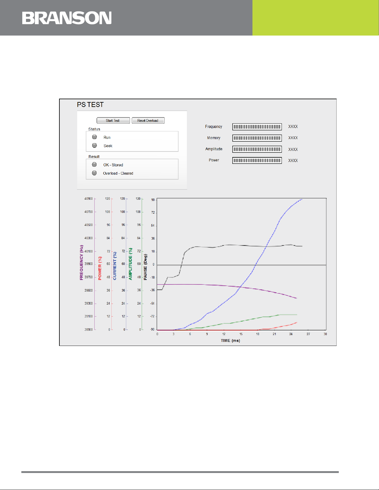
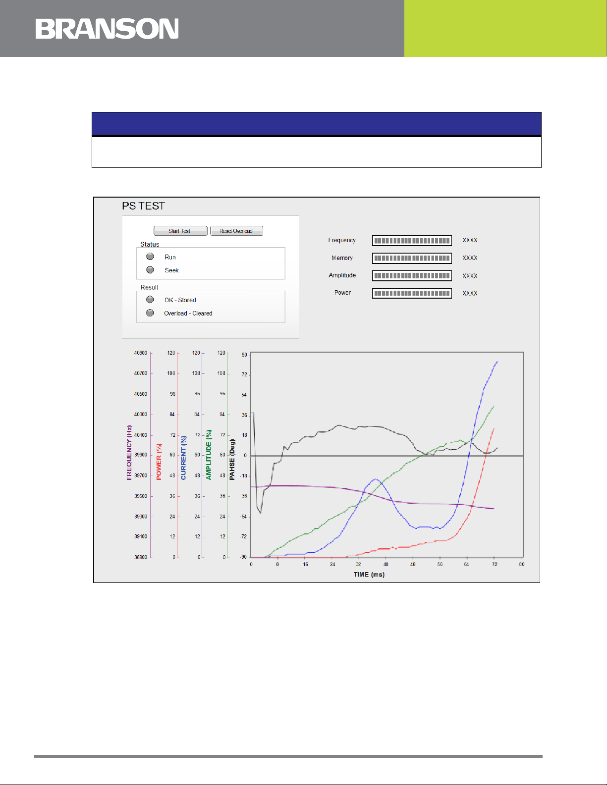
Figure A.9 Graphical Display of the Weld Curves.
At the beginning of the process, the frequency is increased until resonance is reached. At
the point of parallel resonance the weld starts. The following happens:
• The amplitude is controlled to the maximum value, and it remains virtually constant
• The phase changes the polarity
• The current increases to the maximum value and then decreases down to a relatively low
constant value
• The power output increases and then quickly decreases down to a constant value
• The PWM (Pulse Width Modulation) increases and remains constant.
100-412-203 REV. 04 75
A.4.1 Weld Graph Error Analysis
On the following pages, typical sources of error are shown.
NOTICE
Compare your system's curves with these examples to identify some of the possible
problems you may encounter.
Figure A.10Weld Graph, Defective Horn.
This figure resulted in a Overload-Current Alarm.
76 100-412-203 REV. 04
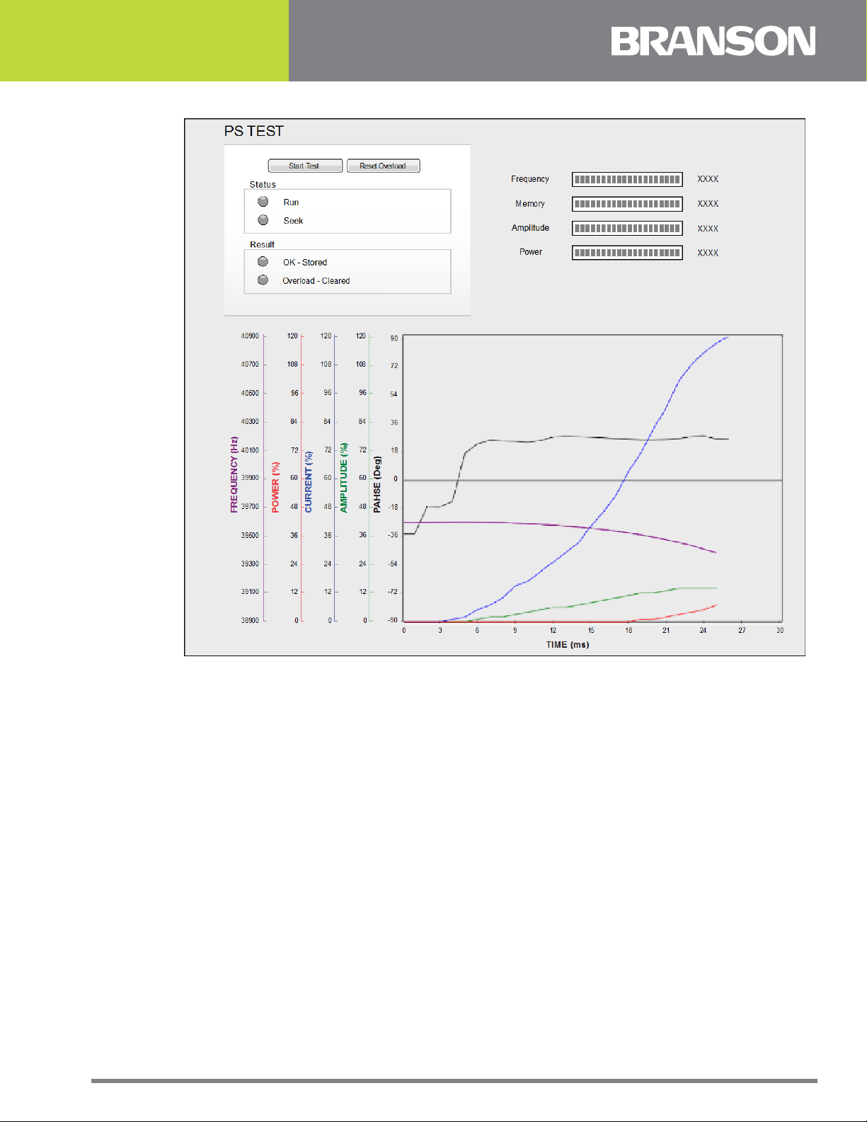
Figure A.11Weld Graph, Defective Converter
This figure resulted in a Overload-Current Alarm.
100-412-203 REV. 04 77
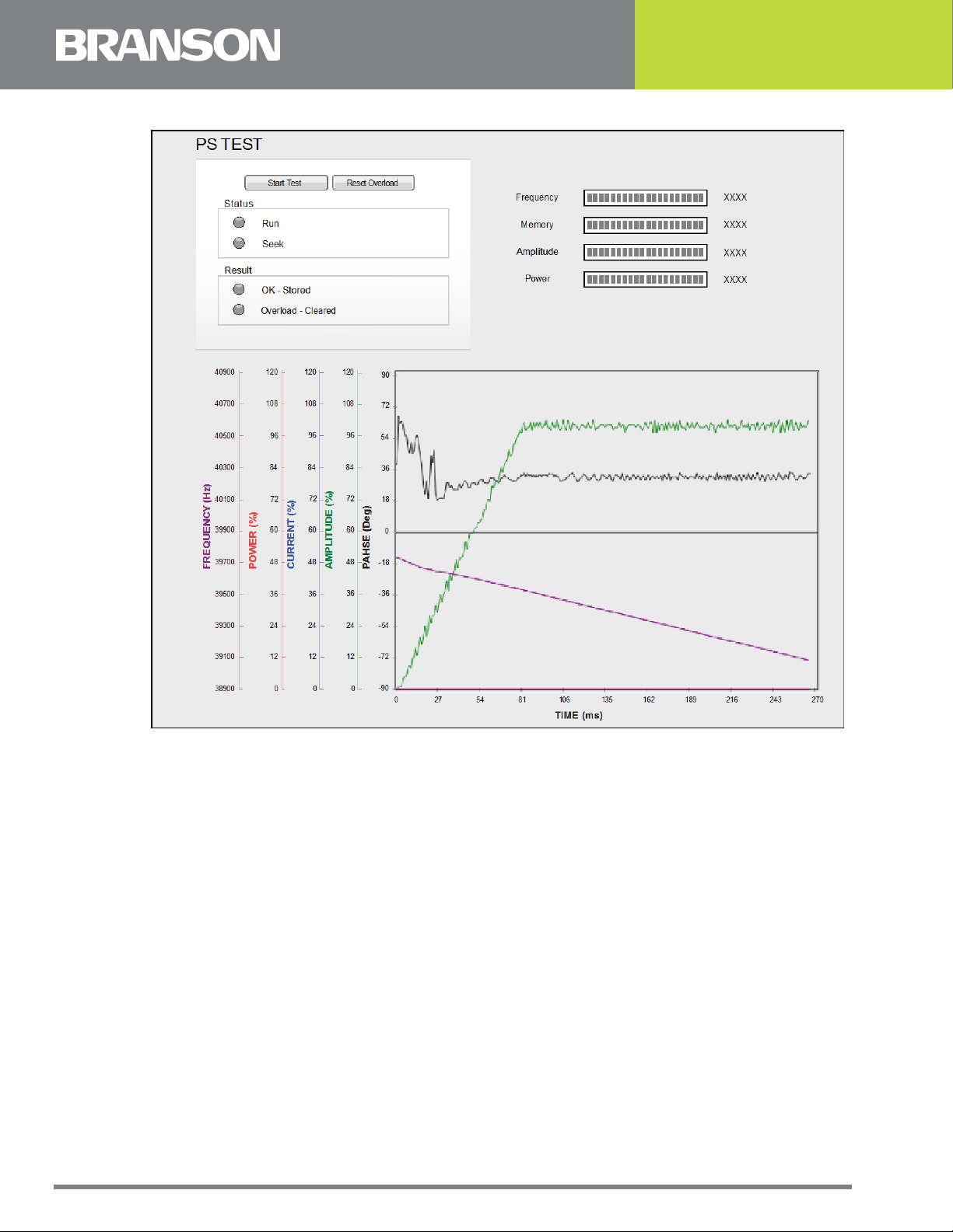
Figure A.12Weld Graph, Open RF Cable.
This figure resulted in a Overload-Frequency Alarm.
78 100-412-203 REV. 04

Index
A
alarm log 37
alarms 62
amplitude 31
B
booster 68
C
coded feedback 64
communication 58
components 67
configuration menu 54
connecting 11
contact Branson 5
D
DCX A ethernet port location 12
DCX F DP ethernet port location 15
DCX F EIP ethernet port location 13
diagnostics menu 44
direct switch 64
E
emissions 3
ethernet port 12
EtherNet/IP 52
event log 39
F
feedback timeout (ms) 64
fieldbus 50
fieldbus test menu 52
G
general precautions 3
graphics of a weld 74
H
history 40
horn 68
horn scan data 70
horn signature 46
I
intended use of the system 3
100-412-203 REV. 04 79

introduction 8
L
limit/cutoff 33
login 28
N
no feedback 64
no RF switching 63
O
overview 26
P
passcode 28
passcodes 60
point to point connection 18, 21
principle 67
profibus DP 53
R
relay switch time (ms) 64
resonance 66
resonance analysis 70
RF selection 64
RF switch 63
RF switching via digital I/O 63
RF switching via fieldbus 63
S
safety and support 1
safety requirements 2
save/recall preset 32
scan horn error analysis 72
seek 44
seek/power up 34
status feedback 64
switch delay (ms) 64
switch with off 64
symbols 2
system 54
system info 36
system requirements 17
U
ultrasonic welding 65
uncoded feedback 64
User I/O 57
user I/O 48
user ID 28
V
view menu 36
80 100-412-203 REV. 04

W
warnings 2
web page interface 7, 25
weld graph error analysis 76
weld graphs 42
Windows 7 18
Windows Vista 18
Windows XP 21
100-412-203 REV. 04 81

82 100-412-203 REV. 04
 Loading...