


BRANSON Automation Guide
EDP 100-214-273
Rev. 1
BRANSON Ultrasonics Corporation
41 Eagle Road
Danbury, Connecticut 06813-1961 U.S.A.
(203) 796-0400
http://www.bransonultrasonics.com

Manual Change Information
At Branson, we strive to maintain our position as the leader in ultrasonics plastics joining,
cleaning and related technologies by continually improving our circuits and components
in our equipment. These improvements are incorporated as soon as they are developed and
thoroughly tested.
Information concerning any improvements will be added to the appropri4ate technical
documentation at its next revision and printing. Therefore, when requesting service
assistance for specific units, note the Revision information found on the cover of this
document.
Foreword
Congratulations on your choice of a Branson Ultrasonics Corporation system!
The Branson 2000-Series system is process equipment for the joining of plastic parts using
ultrasonic energy. It is the newest generation of product using this sophisticated
technology for a variety of customer applications. This Automation Guide is supplemental
to and should be used in conjunction with the documentation set for this system. Thank
you for choosing Branson!

Automation Guide
Table of Contents
1.0- Introduction - - - - - - - - - - - - - - - - - - - - - - - - - - - - - - - - - - 1
2.0- About this Guide - - - - - - - - - - - - - - - - - - - - - - - - - - - - - - - - 1
3.0- Overview of Automation Examples - - - - - - - - - - - - - - - - - - - - - - 2
4.0- Special Features in V9.xx Firmware - - - - - - - - - - - - - - - - - - - - - - 2
5.0- 2000 Series Automation Logic Requirements - - - - - - - - - - - - - - - - - 5
5.1- To Start a Weld Cycle- - - - - - - - - - - - - - - - - - - - - - - - - - - - 6
5.2- Ready Changes State- - - - - - - - - - - - - - - - - - - - - - - - - - - - 6
5.3- Weld (ultrasonics) Finished, Hold Starts - - - - - - - - - - - - - - - - - - - 7
5.4- Hold Finished, Horn Retract Starts - - - - - - - - - - - - - - - - - - - - - 7
5.5- Check for Alarms - - - - - - - - - - - - - - - - - - - - - - - - - - - - - - 7
6.0- Process Flow and Wiring Tables- - - - - - - - - - - - - - - - - - - - - - - - 8
6.1- Actuator with Standard Automation, Process Flow 1 - - - - - - - - - - - - - 9
6.1.1-Wiring Table, Actuator with Standard Automation, Process Flow 1 - - -10
6.1.2-2000 Series Automation Interface, Process Flow 1- - - - - - - - - - -11
6.2- Actuator, External Preset Select, Process Flow 2 - - - - - - - - - - - - - -12
6.2.1-Wiring Table, Actuator, External Preset Select Process Flow 2- - - - -13
6.3- Actuator, Delayed Sonics, Process Flow 3- - - - - - - - - - - - - - - - - -14
6.3.1-Wiring Table, Actuator, Delayed Sonics, Process Flow 3- - - - - - - -15
6.3.2-2000 Series Automation Interface, Process Flow 3- - - - - - - - - - -16
6.4- Actuator, Sonics Disabled, Process Flow 4 - - - - - - - - - - - - - - - - -17
6.4.1-Wiring Table, Actuator, Sonics Disabled, Process Flow 4 - - - - - - -18
6.5- Actuator, Sonics Disabled and Presets, Process Flow 5 - - - - - - - - - - -19
6.5.1-Wiring Table, Actuator, Sonics Disabled and Presets, Process Flow 5 -20
6.6- Actuator, External Preset Select and Delayed Sonics, Process Flow 6 - - - -21
6.6.1-Wiring Table, Actuator External Preset Select and Delayed Sonics, Process Flow 6 - - - - - - - - - - - - - - - - - - - - - - - - - - - - - -22
6.6.2-Wiring Table, Process Flow 6, Required Functions: Logical Sequence -23
6.6.3-Wiring Table, Process Flow 6, PLC Connections- - - - - - - - - - - -24
6.6.4-External Preset Select Binary Table - - - - - - - - - - - - - - - - - -25
6.6.5-Preset Switching Diagrams, 1 of 4- - - - - - - - - - - - - - - - - - -26
3

6.7- Actuator, Delayed Horn Travel, Process Flow 7 - - - - - - - - - - - - - - -30
6.7.1-Wiring Table, Actuator Delayed Horn Travel, Process Flow 7 - - - - -31
6.8- Actuators, Multi-Syncro (simultaneous sonic start), Process Flow 8- - - - - -32
6.9- Interrupting Cycle for Device Position (Hold off on Horn Travel) Externally by PLC
Device, Process Flow 9- - - - - - - - - - - - - - - - - - - - - - - - - - -33
6.9.1-Wiring Table, Interrupting Cycle for Device Position, Process Flow 9 - -34
6.10- Custom Actuator, Process Flow 10- - - - - - - - - - - - - - - - - - - - -35
6.11- Converter Stack, Standard Automation, Process Flow 11 - - - - - - - - - -36
6.11.1-Wiring Table, Converter Stack, Standard Automation, Process Flow 11 -
37
6.11.2-2000 Series Automation, Process Flow 11 (Requires Jumper 100-246-
1178) - - - - - - - - - - - - - - - - - - - - - - - - - - - - - - - - -38
6.12- Converter Stack, External Preset Select, Process Flow 12 - - - - - - - - -39
6.12.1-Wiring Table, Converter Stack, External Preset Select, Process Flow 12
40
7.0- Frequently Asked Questions (FAQ) - - - - - - - - - - - - - - - - - - - - - -41
8.0- Glossary V9.xx - - - - - - - - - - - - - - - - - - - - - - - - - - - - - - - -46
4

Automation Guide Introduction
1.0 Introduction
This guide will help you to better understand the automation features available to you
with the introduction of the version 9.x software to the Branson product line. The major
feature of this software/firmware change is the user-configurable I/O. In the event you
require additional assistance or information, please contact our Product Support department or your local Branson representative.
2.0 About this Guide
This guide describes how to set up some representative automation process options
available with Branson 2000 Series ultrasonic systems that are utilizing software ver
sion 9 or higher.
The information details the wiring hookup to DB9 on the actuator and to J3 on the
power supply that establish the connections needed to accomplish the automation
examples in this guide.
Additionally , detail is given about the use of the newly introduced features available for
configuring the system to perform the desired functions.
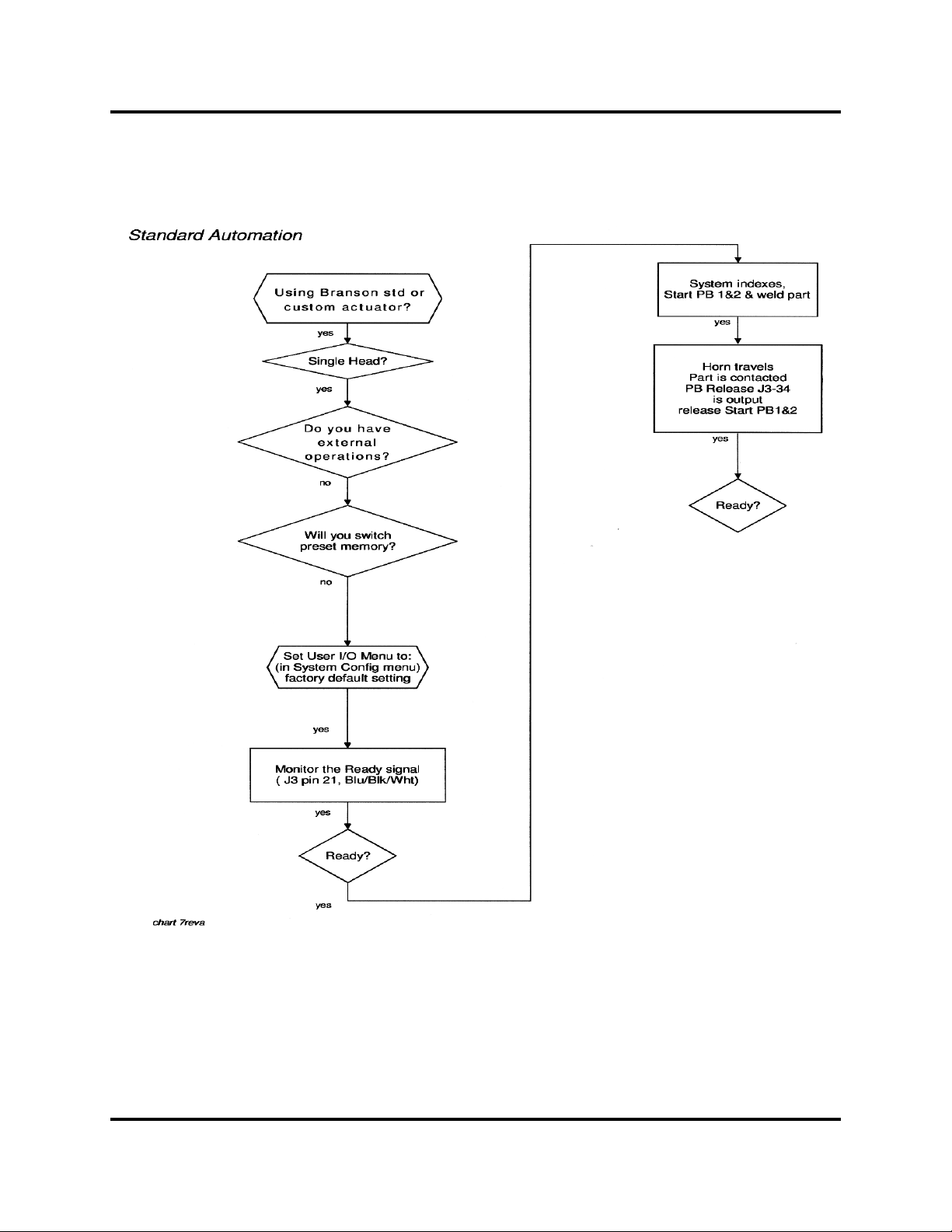
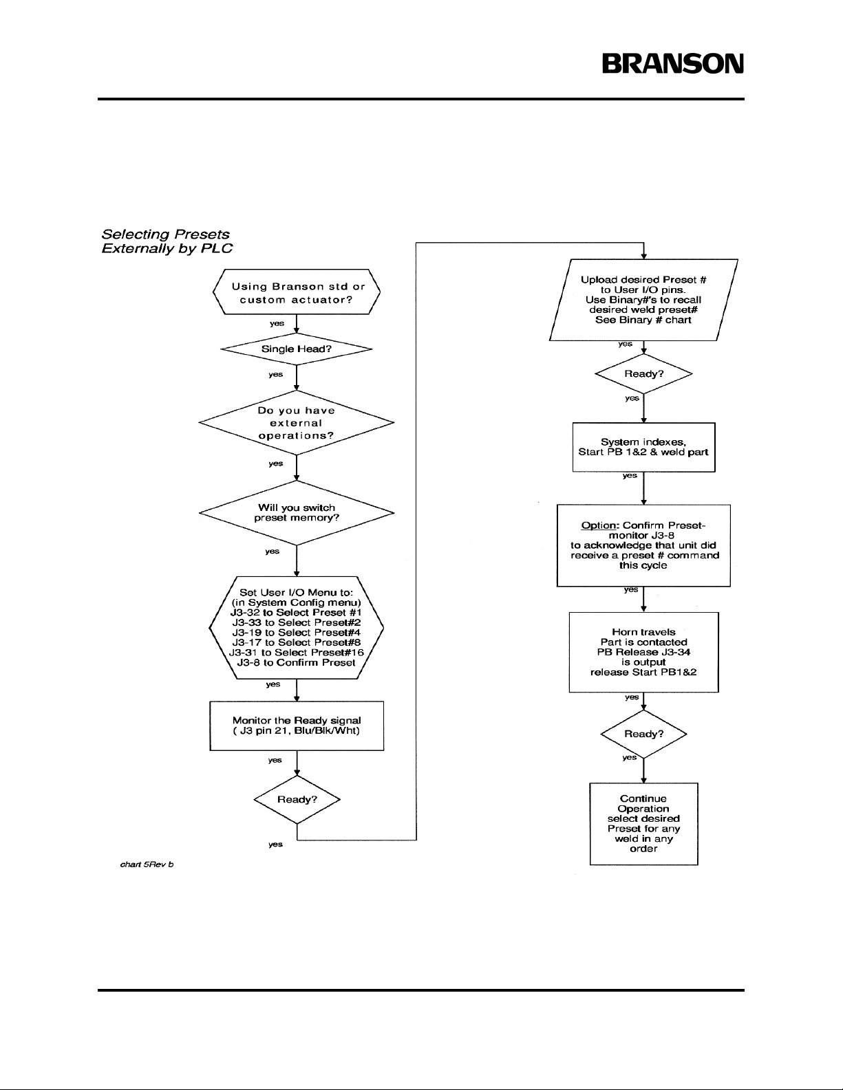
Flow diagrams show the logical sequences for setup that include the wiring steps and
appropriate assignment of menu items with clear and simple content such as; "In Weld
Setup menu turn Ext U/S Delay to On", and "Set User I/O Menu to (in System Config):
J3-32 to Select Preset #1".
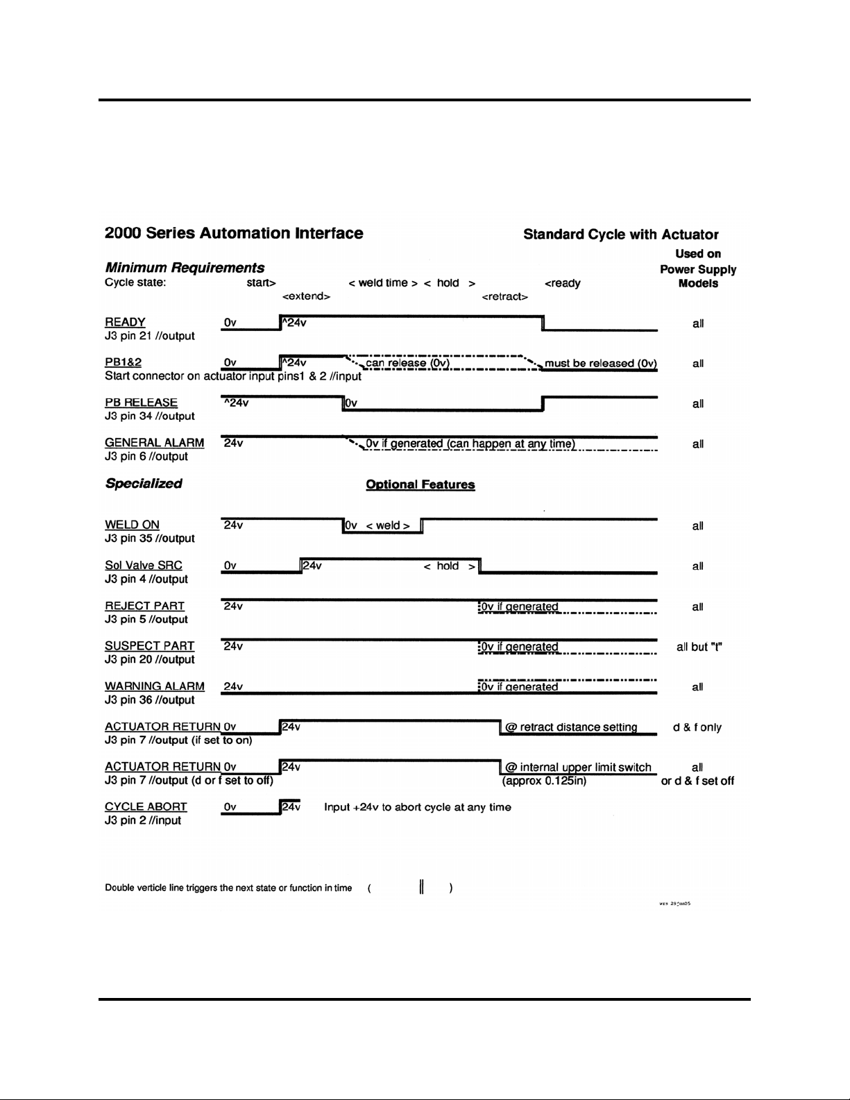
Automation Interface timing diagrams are included for Process Flows 1, 3, 6, and 11.
You can refer to the Frequently Asked Questions (FAQ) Section to enhance your background knowledge about successfully setting up your automation processes.
A Glossary of terminology is also included as an additional useful resource.
This guide is organized into the following sections.
• 3 .0 Overview of Automation Examples: Table lists 12 Automation possibilities, and references their respective Process Flow and Wiring Tables.
• 4.0 Special Features in Ve rsion 9 firmware: Presents and defines Configurable
User Input and Output features.
• 5.0 2000 Series Automation Logic Requirements: Basic minimum system
requirements are presented line by line to run a complete cycle.
• 6.0 Process Flow and Wiring Tables: Defines each of the 12 Automation
examples with complete flow diagrams and wiring tables.
• 7.0 Frequently Asked Questions (FAQ): Lots of useful information relevant
to Branson Automation procedures and processes.
• 8.0 Glossary for Version 9: Definition of terminology used in this Guide.
-
100-214-273 Rev. 1 1

Overview of Automation Examples
3.0 Overview of Automation Examples
This overview shows representative examples of Automation possibilities. Availability is not limited to the
examples shown. Options are shown for use with a Branson actuator, a custom actuator, and a converter
stack. Each Option is referenced to its unique Process Flow diagram and Wiring Table.
.
For Use with a Branson Actuator
Actuator with standard automation Refer to Process Flow 1, Wiring Table 1
Actuator, external preset select Refer to Process Flow 2, Wiring Table 2
Actuator, delayed sonics Refer to Process Flow 3, Wiring Table 3
Actuator, sonics disabled Refer to Process Flow 4, Wiring Table 4
Actuator, sonics disabled, via preset select Refer to Process Flow 5, Wiring Table 5
Actuator, external preset select and delayed sonics. Refer to Process Flow 6, Wiring Table 6
Actuator delayed horn travel Refer to Process Flow 7, Wiring Table 7
Actuators, Multi-Syncro (simultaneous sonic start) Refer to Process Flow 8, Wiring Table 8
Actuator, Interrupting Cycle for
Device Position Refer to Process Flow 9, Wiring Table 9
For Use with a Custom Actuator
Custom actuator Refer to Process Flow 10, N/A
For Use with a Converter Stack
Converter stack, standard automation Refer to Process Flow 11, Wiring Table 10
Converter stack, external preset select Refer to Process Flow 12, Wiring Table 11
4.0 Special Features in V9.xx Firmware
A major feature that is contained in V ersion 9.xx firmware is a user -configurable I/O. This feature is similar
to features in modern home Audio-Video receivers: you can choose what output is present at the digitally
optical jack, and which output is present at the digital hardware jacks, etc. in the 2000 Series welder it allows
the user to configure certain connector J3 pin-outs (6 inputs and 3 outputs) to customer-desired features,
optimizing the unit for specialized applications such as: switching up to 16 preset memo ries, switching converter/horn “stacks”, or for syncing several welders together. You can also “interrupt” a welder cycle for
external events or tests to occur, or allow the end user to choose what alarms amy be most important to their
particular machine or application.
of the Table.
Any pins other than those shown operate similar to
The factory defaulted (as-shipped) settings are chosen
Note: no selection need be chosen for a new V9.xx unit in order to re
Underlined items are new V9.xx features, and are defined at the bottom
previous firmware Versions.
to duplicate earlier model and firmware functions.
place and earlier unit.
2 100-214-273 Rev. 1

NOTE
i
Automation Guide Special Features in V9.xx Firmware
J3 Input Pins Default setting Selectable Setting (any pin)
J3-1 Ext Signal Ext Sonics Delay
J3-17 Select Preset #8 Display Lock Ext Signal
J3-19 Select Preset #4 Sonics Disable Memory Reset
J3-31 Display Lock
J3-32 Select Preset #1 Select Preset #16 (pin 31 only)
J3-33 Select Preset #2
J3 Output Pins Default Setting Selectable Setting (any pin)
J3-8 Disabled
J3-22 Disabled
J3-36 Disabled Confirm Preset Modified Alarm
Sync In Ext Start (input)
Cycle Okay Overload Alarm
External Beeper Note
No Cycle Alarm Ext Start (output)
Missing Part Sync Out
Note: Regardless of current settings, by choosing factory
default setting in Menu, you will restore factory
settings.
All voltages shown in this manual are direct current (DC) unless otherwise noted.
Signal Definitions (Refer to Section 8.0, Glossary for Version 9 for additional definitions.)
Confirm Preset: A user output signal that will indicate that a weld cycle preset # has been input from the
external controller.
Cycle Okay: A user output signal that indicates no detectable alarm conditions occurred during the last weld
cycle.
External Beeper: An output pin that operates the same as the internal beeper, and could operate an external
(louder) device or light.
100-214-273 Rev. 1 3

Special Features in V9.xx Firmware
Ext Signal: Note: Not a new V9.xx feature but repeated here for clarity . Now the hardware pin and function
is selectable in the User I/O menu.
Used as input to allow external input to trigger amplitude or force change (model dependant).
Optionally used as the start cycle input when in Hand Held mode.
Ext Sonics Delay: A cycle where the ultrasonics are not started after the horn contacts the workpiece until
an external device has determined that the cycle should continue. It may be a test apparatus or perhaps a
part-marking operation.
Note: The Cycle Abort input can be used to end the welder cycle and not waste time on a workpiece that the
external apparatus determined to be a reject.
Ext Start (input and output): These are both input and output signals, and both must be turned on and
assigned a hardware input and output pin in order to function.
Once the unit has received a legitimate start input the External Start output pin activates an external device
(horn clamp cylinder, sound enclosure door , part in position, etc) before moving the horn. When the external
device becomes active, it then signals the External Start input to commence the welder’s horn travel and
weld cycle. To enable this feature, select the System Configuration menu, then User I/O menu.
While in that menu you can also set “Ext Start Dly” of up to 10.0 sec. to wait before receiving the External
Start input before setting an alarm.
Modified Alarm: A user output signal that indicates a user-set compensating condition occurred, (Only
energy at this time).
Note: An alarm condition of the lowest priority.
Overload Alarm: A user output signal that will indicate that a power supply overload condition occurred
during the last weld, test or seek cycle.
Select Preset #16 (pin 31 only):
Sonics Disable: When this User I/O input is active, ultrasonic energy is forced off. If active throughout a
weld cycle, a “dry” cycle will occur: should the weld mode be indeterminate (energy, power, etc) then the
time normally used for the “weld” will extend out to the maximum allowed.
Sync In Sync Out (syncro weld cycle): This is when multiple welders cycle against the same workpiece, and
their ultrasonic power is started simultaneously in Sync for a particular application issue. Sync In is used in
conjunction with Sync Out.
4 100-214-273 Rev. 1

NOTE
i
NOTE
i
NOTE
i
Automation Guide 2000 Series Automation Logic Requirements
(Another option would be to release all the horns from the workpiece simultaneously. You can use a longer
than required hold time on each unit, then apply Cycle Abort to all the welders to make all retract simultaneously.)
5.0 2000 Series Automation Logic Requirements
Logic conditions shown are defaulted to factory shipped condition, with no configuration
changes.This information applies to standard automation, such as a rotary index table application.
Minimum system requirement for Automated Operation:
Underlined actions must be done in the order shown by system controls.
You must provide an Emergency Stop function through the start cable (DB9 connecto r on rear of actuator).
• Connect pins 8 (Yellow) and 9 (Purple) together, and then connect to a Normally Closed contact
of a switch or relay.
• Connect pins 3 ( Red) and 4 (Green) together, and then connect to the other Normally Closed contact of the same switch or relay.
These connections must be closed for normal operation, opened in an abnormal condition. Keep in mind this
closed condition is needed even if the automation system is in a powered off state, for actions such as maintenance or calibration to be performed on the ultrasonic welder.
Do not use this as a commonly used interlock, as a Reset input: apply +24VDC to J3 (User I/O HD44 connector) pin 3 (Green/Black) will be required to clear any Emergency Stop condition.
If you wish to be able to abort a weld cycle at any time and have the welder retract back
towards the home or rest position, use the Cycle Abort input: apply +24VDC to J3 (User I/O
HD44 connector) pin 2 (Red/Black).
100-214-273 Rev. 1 5

2000 Series Automation Logic Requirements
5.1 To Start a Weld Cycle
The only time it is acceptable to “start” or initiate a cycle is when a welder is in the “ready” state. If the
welder is Ready, it can be started.
Monitor Ready: J3 (User I/O HD44 connector) pin 21 @ 0v, (Blue/Black/White)
Initiate the cycle by applying +24VDC simultaneously (preferably sourced by the 2000 Series controls) or
a contact closure within a maximum allowable stagger time of 200 ms. The voltage, or contact closure, must
continue to be held closed (for now). You can get a signal flagging when to release later.
T o Start Cycle: (DB9 connector on rear of actuator) Apply +24 (To start pins 1 (Black) and 2 (White) on the
actuator connector, (use pins 6 (Blue) and 7 (Orange) as +24VDC voltage source), or
Close contacts (To start pins 1 (Black) and 7 (Orange), and 2 (White) and 6 (Blue) on the actuator connector.You may wish, dependant on application, to monitor the following signals.
J3 (User I/O HD44 connector) output signals:
• General Alarm is off, 24VDC, pin 6 (Black /White)
This gets flagged from any other alarm, useful as a master alarm. Recommended.
• Reject Alarm is off, 24VDC, pin 5 (Blue/Black)
This gets flagged from a reject welding parameter alarm.
• Suspect Alarm is off, 24VDC, pin 20 (Orange/Black/White)
This gets flagged from a suspect welding parameter alarm.
• Warning Alarm is off, 24VDC,pin 36 (Orange/Red/Green) )
This gets flagged when a alarm is imminent, or that an authorized cycle modification occurred.
• Weld On is off, 24VDC, pin 35 (Green/White/Blue)
Ultrasonics are activated
• Actuator Clear goes off, 24VDC, pin 7 (Red/White)
Actuator is at height of upper limit switch, or height setting is set.
After the start circuit is activated the internal solenoid valve (S/V) will be activated allowing the horn to
travel toward the workpiece. After the point of contact, force will develop against the workpiece. When the
2000 Series controls sense the trigger force set point the welder advances to the weld on state. Ultrasonics
will start, and the start switches may now be released. We recommend monitoring the PB Release signal as
the event to flag the release of the start signal. Had either or both start switches been released at any time
before that point, the welder would abort the cycle, retract back towards the home or rest position, and display an error message.
5.2 Ready Changes State
Ready changes state: S/V goes on; Weld trigger occurs,
PB Release signal goes on, J3 User I/O HD44 connector 0v @ pin 34 (Red/White/Green).
6 100-214-273 Rev. 1

Automation Guide 2000 Series Automation Logic Requirements
Then, on DB9 connector on rear of actuator , apply 0v to start pins 1 and 2 on the actuat or connector before
welder returns to home position, or
Release contacts on pins 1 and 7, 2 and 6 on the actuator connector before the welder returns to home position.
At User I/O HD44 connector:
Ready J3 pin 21 Blue/Black/ White @24VDC
SOL VALVE SRC pin 4 Orange/Black @ 24VDC
SOL VALVE RTN pin 16 Black/White/Red @ 0v
Weld ON goes on 0v @ pin 35 Green/White/Blue
5.3 Weld (ultrasonics) Finished, Hold Starts
User I/O HD44 connector:
Weld On goes off 24VDC @ pin 35 Green/White/Blue
5.4 Hold Finished, Horn Retract Starts
User I/O HD44 connector:
S/V goes off:
SOL VALVE SRC pin 4 @ 0v Orange/Black
SOL VALVE RTN pin 16 @ 0v Black/White/Red
Actuator clear pin 7 @ 0v Red/White
ACT RTN pin 7 @ 0v at setting
Horn is back to home position.
Start switches must be released by now
5.5 Check for Alarms
User I/O HD44 connector:
Return to Ready state.
Monitor that General Alarm is off 24VDC (pin 6 Black/White) recommended.
Wait for Ready (J3 pin 21 @ 0v Blue/Black/White.
100-214-273 Rev. 1 7

NOTE
i
Process Flow and Wiring Tables
6.0 Process Flow and Wiring Tables
Each Process Flow diagram has a wiring table associated with setting up the connections to DB-9 on the
rear of the actuator, and HD-44 which is the User I/O connector on the rear of the power supply. One exception to this is “For Use with a Custom Actuator” Process Flow 10, which has no wiring table associated with
it.
Process Flow 6 additionally has Preset Switching Diagrams, PLC Wiring T able, and an External Preset Select Binary Table.
8 100-214-273 Rev. 1
Automation Guide Process Flow and Wiring Tables
6.1 Actuator with Standard Automation, Process Flow 1
100-214-273 Rev. 1 9

NOTE
i
Process Flow and Wiring Tables
6.1.1 Wiring Table, Actuator with Standard Automation, Process Flow 1
All voltages shown in this manual are direct current (DC) unless otherwise noted
#1 Process Flowchart 1
Base/Start connector on
actuator rear DB-9
Step Signal Name Pin Colors Direction- Signal Type Definition
1 PB2 RETURN 1 Black Input 24V True PB (actuator start) input
2 PB1 RETURN 2 White Input 24V True PB (actuator start) input
3 E-STOP RETURN 3 Red Input 24V True E-STOP input
4 E-STOP RETURN 4 Green Input 24V True E-STOP input
J3 User I/O connector on
power supply rear HD-44
Signal Name Pin # Colors Direction Signal Type Definition
5 EXT_RESET 3 Grn/Blk Input 24V True System Reset
6 G_ALARM 6 Blk/Wht Output 0V True General Alarm
7 24V RETURN 12 Orn/Red 24V Return 24V Return
8 24V SOURCE 13 Blu/Red Output +24V Source +24V Source
9 READY 21 Blu/Blk/Wht Output 0V True Ready Output
10 24V RETURN 27 Blu/Wht/Orn 24V Return 24V Return
11 24V SOURCE 28 Blk/Wht/Orn +24V +24V Source
12 PB RELEASE 34 Red/Wht/Grn Output 0V True PB Release
13 24V RETURN 41 Grn/Orn/Red 24V Return 24V Return
14 24V SOURCE 42 Orn/Red/Blu +24V +24V Source
10 100-214-273 Rev. 1
Automation Guide Process Flow and Wiring Tables
6.1.2 2000 Series Automation Interface, Process Flow 1
100-214-273 Rev. 1 11
Process Flow and Wiring Tables
6.2 Actuator, External Preset Select, Process Flow 2
12 100-214-273 Rev. 1

NOTE
i
Automation Guide Process Flow and Wiring Tables
6.2.1 Wiring Table, Actuator, External Preset Select Process Flow 2
All voltages shown in this manual are direct current (DC) unless otherwise noted
#2 Process Flowchart 2
Base/Start connector on
actuator rear DB-9
Step Signal Name Pin Colors Direction- Signal Type Definition
1 PB2 RETURN 1 Black Input 24V True PB (actuator start) input
2 PB1 RETURN 2 White Input 24V True PB (actuator start) input
3 E-STOP RETURN 3 Red Input 24V True E-STOP input
4 E-STOP RETURN 4 Green Input 24V True E-STOP input
J3 User I/O connector on
power supply rear HD-44
Signal Name Pin # Colors Direction Signal Type Definition
5 EXT_RESE
Blk/Wht/Orn +24V +24V Source
15 User definable input 31 Wht/Red/Blu Input 24V True Set:SELECT PRESET#16
16 User definable input 32 Blk/Grn/Wht Input 24V True Set:SELECT PRESET#1
17 User definable input 33 Wht/Blk/Grn Input 24V True Set:SELECT PRESET#2
18 PB RELEASE 34 Red/Wht/Grn Output 0V True PB Release
19 24V RETURN 41 Grn/Orn/Red 24V Return 24V Return
20 24V SOURCE 42 Orn/ Red/Blu +24V +24V Source
100-214-273 Rev. 1 13

Process Flow and Wiring Tables
6.3 Actuator, Delayed Sonics, Process Flow 3
14 100-214-273 Rev. 1

NOTE
i
Automation Guide Process Flow and Wiring Tables
6.3.1 Wiring Table, Actuator, Delayed Sonics, Process Flow 3
All voltages shown in this manual are direct current (DC) unless otherwise noted
#3 Process Flowchart 3
Base/Start connector on
actuator rear DB-9
Step Signal Name Pin Colors Direction- Signal Type Definition
1 PB2 RETURN 1 Black Input 24V True PB (actuator start) input
2 PB1 RETURN 2 White Input 24V True PB (actuator start) input
3 E-STOP RETURN 3 Red Input 24V True E-STOP input
4 E-STOP RETURN 4 Green Input 24V True E-STOP input
J3 User I/O connector on
power supply rear HD-44
Signal Name Pin # Colors Direction Signal Type Definition
5 User definable input 1 Wht/Blk Input 24V True Set:EXT SONICS DELAY
5 EXT_RESET 3 Grn/Blk Input 24V True System Reset
6 G_ALARM 6 Blk/Wht Output 0V True Gen eral Alarm
7 24V RETURN 12 Orn/Red 24V Return 24V Return
8 24V SOURCE 13 Blu/Red Output +24V Source +24V Source
9 READY 21 Blu/Blk/Wht Output 0V True Ready Output
10 24V RETURN 27 Blu/Wht/Orn 24V Return 24V Return
11 24V SOURCE 28 Blk/Wht/Orn +24V +24V Source
12 PB RELEASE 34 Red/Wht/Grn Output 0V True PB Release
13 24V RETURN 41 Grn/Orn/Red 24V Return 24V Return
14 24V SOURCE 42 Orn/Red/Blu +24V +24V Source
100-214-273 Rev. 1 15

Process Flow and Wiring Tables
6.3.2 2000 Series Automation Interface, Process Flow 3
16 100-214-273 Rev. 1

Automation Guide Process Flow and Wiring Tables
6.4 Actuator, Sonics Disabled, Process Flow 4
100-214-273 Rev. 1 17

NOTE
i
Process Flow and Wiring Tables
6.4.1 Wiring Table, Actuator, Sonics Disabled, Process Flow 4
All voltages shown in this manual are direct current (DC) unless otherwise noted
#4 Process Flowchart 4
Base/Start connector on
actuator rear DB-9
Step Signal Name Pin Colors Direction- Signal Type Definition
1 PB2 RETURN 1 Black Input 24V True PB (actuator start) input
2 PB1 RETURN 2 White Input 24V True PB (actuator start) input
3 E-STOP RETURN 3 Red Input 24V True E-STOP input
4 E-STOP RETURN 4 Green Input 24V True E-STOP input
J3 User I/O connector on
power supply rear HD-44
Signal Name Pin # Colors Direction Signal Type Definition
5 User definable input 1 Wht/Blk Input 24V True Set: SONICS DISABLE
5 EXT_RESET 3 Grn/Blk Input 24V True System Reset
6 G_ALARM 6 Blk/Wht Output 0V True Gen eral Alarm
7 24V RETURN 12 Orn/Red 24V Return 24V Return
8 24V SOURCE 13 Blu/Red Output +24V Source +24V Source
9 READY 21 Blu/Blk/Wht Output 0V True Ready Output
10 24V RETURN 27 Blu/Wht/Orn 24V Return 24V Return
11 24V SOURCE 28 Blk/Wht/Orn +24V +24V Source
12 PB RELEASE 34 Red/Wht/Grn Output 0V True PB Release
13 24V RETURN 41 Grn/Orn/Red 24V Return 24V Return
14 24V SOURCE 42 Orn/Red/Blu +24V +24V Source
18 100-214-273 Rev. 1

Automation Guide Process Flow and Wiring Tables
6.5 Actuator, Sonics Disabled and Presets, Process Flow 5
100-214-273 Rev. 1 19

NOTE
i
Process Flow and Wiring Tables
6.5.1 Wiring Table, Actuator, Sonics Disabled and Presets, Process Flow 5
All voltages shown in this manual are direct current (DC) unless otherwise noted
#5 Process Flowchart 5
Base/Start connector on
actuator rear DB-9
Step Signal Name Pin Colors Direction- Signal Type Definition
1 PB2 RETURN 1 Black Input 24V True PB (actuator start) input
2 PB1 RETURN 2 White Input 24V True PB (actuator start) input
3 E-STOP RETURN 3 Red Input 24V True E-STOP input
4 E-STOP RETURN 4 Green Input 24V True E-STOP input
J3 User I/O connector on
power supply rear HD-44
Signal Name Pin # Colors Direction Signal Type Definition
5 User definable input 1 Wht/Blk Input 24V True Set:EXT SONICS DISABLE
6 EXT_RESET 3 Grn/Blk Input 24V True System Reset
7 G_ALARM 6 Blk/Wht Output 0V True Gen eral Alarm
8 User definable output 8 Grn/Wht Output 24V True Set: Confirm Preset
9 24V RETURN 12 Orn/Red 24V Return 24V Return
10 24V SOURCE 13 Blu/Red Output +24V Source +24V Source
11 User definable input 17 Wht/Blk/Red Input 24V True Set:SELECT PRESET #8
12 User definable input 19 Grn/Blk/Wht
13 READY 21 Blu/Blk/Wht Output 0V True Ready Output
14 24V RETURN 27 Blu/Wht/Orn 24V Return 24V Return
15 24V SOURCE 28 Blk/Wht/Orn +24V +24V Source
16 User definable input 31 Wht/Red/Blu Input 24V True Set:SELECT PRESET#16
17 User definable input 32 Blk/Grn/Wht Input 24V True Set:SELECT PRESET#1
User definable input 33 Wht/Blk/Grn Input 24V True Set:SELECT PRESET#2
18
19 PB RELEASE 34 Red/Wht/Grn Output 0V True PB Release
20 User definable output 36 Orn/Red/Grn Output 24V True Set:NOTE
21 24V RETURN 41 Grn/Orn/Red 24V Return 24V Return
22 24V SOURCE 42 Orn/Red/Blu +24V +24V Source
20 100-214-273 Rev. 1

Automation Guide Process Flow and Wiring Tables
6.6 Actuator, External Preset Select and Delayed Sonics, Process Flow 6
100-214-273 Rev. 1 21

NOTE
i
Process Flow and Wiring Tables
6.6.1 Wiring Table, Actuator External Preset Select and Delayed Sonics, Process Flow 6
All voltages shown in this manual are direct current (DC) unless otherwise noted
#6 Process Flowchart 6
Base/Start connector on
actuator rear DB-9
Step Signal Name Pin Colors Direction- Signal Type Definition
1 PB2 RETURN 1 Black Input 24V True PB (actuator start) input
2 PB1 RETURN 2 White Input 24V True PB (actuator start) input
3 E-STOP RETURN 3 Red Input 24V True E-STOP input
4 E-STOP RETURN 4 Green Input 24V True E-STOP input
J3 User I/O connector on
power supply rear HD-44
Signal Name Pin # Colors Direction Signal Type Definition
5 User definable input 1 Wht/Blk Input 24V True Set:EXT SONICS DELAY
6 EXT_RESET 3 Grn/Blk Input 24V True System Reset
7 G_ALARM 6 Blk/Wht Output 0V True Gen eral Alarm
8 24V RETURN 12 Orn/Red 24V Return 24V Return
9 24V SOURCE 13 Blu/Red Output +24V Source +24V Source
10 User definable input 17 Wht/Blk/Red Input 24V True Set:SELECT PRESET #8
11 User definable input 19 Grn/Blk/Wht Input 24V True Set:SELECT PRESET #4
12 READY 21 Blu/Blk/Wht Output 0V True Ready Output
13 24V RETURN 27 Blu/Wht/Orn 24V Return 24V Return
14 24V SOURCE 28 Blk/Wht/Orn +24V +24V Source
15 User definable input 31 Wht/Red/Blu Input 24V True Set:SELECT PRESET#16
16 User definable input 32 Blk/Grn/Wht Input 24V True Set:SELECT PRESET#1
17 User definable input 33 Wht/Blk/Grn Input
18 PB RELEASE 34 Red/Wht/Grn Output 0V True PB Release
19 24V RETURN 41 Grn/Orn/Red 24V Return 24V Return
20 24V SOURCE 42 Orn/Red/Blu +24V +24V Source
24V True Set:SELECT PRESET#2
22 100-214-273 Rev. 1

3
4
NOTE
i
Automation Guide Process Flow and Wiring Tables
6.6.2 Wiring Table, Process Flow 6, Required Functions: Logical Sequence
All voltages shown in this manual are direct current (DC) unless otherwise noted
100-214-273 Rev. 1 23

Process Flow and Wiring Tables
6.6.3 Wiring Table, Process Flow 6, PLC Connections
Pin Definition, DB9, Actuator
1 PB (actuator start) input
2 PB (actuator start) input
6 Source 24VDC (for hard contact)
7 Source 24VDC (for hard contact)
8 Source 24VDC (for hard contact)
9 Source 24VDC (for hard contact)
3 E-STOP input
4 E-STOP input
Definition, J3, Power Supply Pin Definition, cont´d
• 1 • Set: EXT SONICS DELAY 23 10VDC reference voltage from PS
2 Cycle Abort 24 Amplitude signal from PS
3 System Reset 25 User Frequency offset control signal
4 SV1 Source 26 Run signal from PS
5 Reject Alarm 27 24VDC Return
6 General Alarm 28 +24VDC Source
7 Actuator return signal 29 General Alarm Relay
• 8 • AVAILABLE 30 Weld On Relay
9 Memory Signal P/S • 31 • Set: SELECT PRESET #16
10 User Amplitude control signal • 32 • Set: SELECT PRESET #1
11 Memory Clear signal to PS • 33 • Set: SELECT PRESET #2
12 24VDC Return 34 PB Release
13 +24VDC Source 35 Weld On
14 Relay Contact Output 1 • 36 • AVAILABLE
15 Relay Contact Output 2 37 Power Signal from PS
16 SV1 Return 38 Frequency Signal from PS
• 17 • Set: SELECT PRESET #8 39 Seek Signal from PS
18 External Seek Input 40 Store Signal from PS
• 19 • Set: SELECT PRESET #4 41 24V Return
20 Suspect Part Alarm 42 +24V Source
21 Ready Output 43 Relay Contact Output
•22 •AVAILABLE 44 Relay Contact Output
24 100-214-273 Rev. 1

Automation Guide Process Flow and Wiring Tables
6.6.4 External Preset Select Binary Table
User I/O Input Pins When using External Preset Select
User I/O Input Pin #
31 17 19 33 32
PRESET
1 OFF OFF OFF OFF ON 1
2 OFF OFF OFF ON OFF 2
3 OFF OFF OFF ON ON 3
4 OFF OFF ON OFF OFF 4
5 OFF OFF ON OFF ON 5
6 OFF OFF ON ON OFF 6
7 OFF OFF ON ON ON 7
8 OFF ON OFF OFF OFF 8
9 OFF ON OFF OFF ON 9
10 OFF ON OFF ON OFF 10
11 OFF ON OFF ON ON 11
12 OFF ON ON OFF OFF 12
13 OFF ON ON OFF ON 13
14 OFF ON ON ON OFF 14
15 OFF ON ON ON ON 15
16 ON OFF OFF OFF OFF 16
(16) (8) (4) (2) (1)
(16) (8) (4) (2) (1)
31 17
19 33 32
PRESET
100-214-273 Rev. 1 25

Process Flow and Wiring Tables
6.6.5 Preset Switching Diagrams, 1 of 4
26 100-214-273 Rev. 1

Automation Guide Process Flow and Wiring Tables
Preset Switching Diagram, 2 of 4 continued
100-214-273 Rev. 1 27

Process Flow and Wiring Tables
Preset Switching Diagrams, 3 of 4 continued
28 100-214-273 Rev. 1

Automation Guide Process Flow and Wiring Tables
Preset Switching Diagrams, 4 of 4 continued
100-214-273 Rev. 1 29

Process Flow and Wiring Tables
6.7 Actuator, Delayed Horn Travel, Process Flow 7
30 100-214-273 Rev. 1

NOTE
i
Automation Guide Process Flow and Wiring Tables
6.7.1 Wiring Table, Actuator Delayed Horn Travel, Process Flow 7
All voltages shown in this manual are direct current (DC) unless otherwise noted
#7 Process Flowchart 7
Base/Start connector on
actuator rear DB-9
Step Signal Name Pin Colors Direction- Signal Type Definition
1 PB2 RETURN 1 Black Input 24V True PB (actuator start) input
2 PB1 RETURN 2 White Input 24V True PB (actuator start) input
3 E-STOP RETURN 3 Red Input 24V True E-STOP input
4 E-STOP RETURN 4 Green Input 24V True E-STOP input
J3 User I/O connector on
power supply rear HD-44
Signal Name Pin # Colors Direction Signal Type Definition
5 User definable input 1 Wht/Blk Input 24V True Set:EXTERNAL START
6 EXT_RESET 3 Grn/Blk Input 24V True System Reset
7 G_ALARM 6 Blk/Wht Output 0V True Gen eral Alarm
8 User definable output 8 Grn/Wht Output 24V True Set: EXTERNAL START
9 24V RETURN 12 Orn/Red 24V Return 24V Return
10 24V SOURCE 13 Blu/Red Output +24V Source +24V Source
11 READY 21 Blu/Blk/Wht Output 0V True Ready Output
12 24V RETURN 27 Blu/Wht/Orn 24V Return 24V Return
13 24V SOURCE 28 Blk/Wht/Orn +24V +24V Source
14 PB RELEASE 34 Red/Wht/Grn Output 0V True PB Release
15 24V RETURN 41 Grn/Orn/Red 24V Return 24V Return
16 24V SOURCE 42 Orn/Red/Blu +24V +24V Source
100-214-273 Rev. 1 31

Process Flow and Wiring Tables
6.8 Actuators, Multi-Syncro (simultaneous sonic start), Process Flow 8
1. All welders get start signal from external control.
2. All welders move down to the part to be welded.
3. All welders reach trigger.
4. On all welders sonics is not activated because at this point, Sync In and Ext U/S Delay is missing.
5. On welder 2, Sync Out is activated by Sync In (=PB Release welder 1) and has reached trigger.
Chain sequence links Sync Out 2-Sync In 3-Sync Out 3-Sync in X-Sync Out X-Sync in 1-Sync Out 1
6. Sync Out 1 activates all Ext U/S Delay inputs, see dotted line. Ultrasonics is started on all welders at
the same time.
Star Ext U/S Delay
Sync In
Welder 1
PB Release Sync Out
Sync In Ext U/S Delay
Welder 2
Sync Out Start
Sync In Ext U/S Delay
Welder 3
Sync Out Start
Sync In Ext U/S Delay
Welder X
Sync Out Start
32 100-214-273 Rev. 1

Automation Guide Process Flow and Wiring Tables
6.9 Interrupting Cycle for Device Position (Hold off on Horn T ravel) Externally by PLC Device, Process Flow 9
100-214-273 Rev. 1 33

NOTE
i
Process Flow and Wiring Tables
6.9.1 Wiring Table, Interrupting Cycle for Device Position, Process Flow 9
All voltages shown in this manual are direct current (DC) unless otherwise noted
#9 Process Flowchart 9
Base/Start connector on
actuator rear DB-9
Step Signal Name Pin Colors Direction- Signal Type Definition
1 PB2 RETURN 1 Black Input 24V True PB (actuator start) input
2 PB1 RETURN 2 White Input 24V True PB (actuator start) input
3 E-STOP RETURN 3 Red Input 24V True E-STOP input
4 E-STOP RETURN 4 Green Input 24V True E-STOP input
J3 User I/O connector on
power supply rear HD-44
Signal Name Pin # Colors Direction Signal Type Definition
5 User definable input 1 Wht/Blk Input 24V True Set:EXTERNAL START
6 EXT_RESET 3 Grn/Blk Input 24V True System Reset
7 G_ALARM 6 Blk/Wht Output 0V True Gen eral Alarm
8 User definable output 8 Grn/Wht Output 24V True Set: EXTERNAL START
9 24V RETURN 12 Orn/Red 24V Return 24V Return
10 24V SOURCE 13 Blu/Red Output +24V Source +24V Source
11 READY 21 Blu/Blk/Wht Output 0V True Ready Output
12 24V RETURN 27 Blu/Wht/Orn 24V Return 24V Return
13 24V SOURCE 28 Blk/Wht/Orn +24V +24V Source
14 PB RELEASE 34 Red/Wht/Grn Output 0V True PB Release
15 24V RETURN 41 Grn/Orn/Red 24V Return 24V Return
16 24V SOURCE 42 Orn/Red/Blu +24V +24V Source
34 100-214-273 Rev. 1

Automation Guide Process Flow and Wiring Tables
6.10 Custom Actuator, Process Flow 10
100-214-273 Rev. 1 35

Process Flow and Wiring Tables
6.11 Converter Stack, Standard Automation, Process Flow 11
36 100-214-273 Rev. 1

NOTE
i
Automation Guide Process Flow and Wiring Tables
6.11.1 Wiring Table, Converter Stack, Standard Automation, Process Flow 11
All voltages shown in this manual are direct current (DC) unless otherwise noted
#10 Process Flowchart 11
Install 100-246-1178
jumper box into J7
J3 User I/O connector on
power supply rear HD-44
Signal Name Pin # Colors Direction Signal Type Definition
1 User definable input 1 Wht/Blk Input 24V True Set:EXT SIGNAL
2 EXT_RESET 3 Grn/Blk Input 24V True System Reset
3 G_ALARM 6 Blk/Wht Output 0V True General Alarm
4 24V RETURN 12 Orn/Red 24V Return 24V Return
5 24V SOURCE 13 Blu/Red Output +24V Source +24V Source
6 READY 21 Blu/Blk/Wht Output 0V True Ready Output
7 24V RETURN 27 Blu/Wht/Orn 24V Return 24V Return
8 24V SOURCE 28 Blk/Wht/Orn +24V +24V Source
9 PB RELEASE 34 Red/Wht/Grn Output 0V True PB Release
10 24V RETURN 41 Grn/Orn/Red 24V Return 24V Return
11 24V SOURCE 42 Orn/Red/Blu +24V +24V Source
100-214-273 Rev. 1 37

Process Flow and Wiring Tables
6.11.2 2000 Series Automation, Process Flow 11 (Requires Jumper 100-246-1178)
38 100-214-273 Rev. 1

Automation Guide Process Flow and Wiring Tables
6.12 Converter Stack, External Preset Select, Process Flow 12
100-214-273 Rev. 1 39

NOTE
i
Process Flow and Wiring Tables
6.12.1 Wiring Table, Converter Stack, External Preset Select, Process Flow 12
All voltages shown in this manual are direct current (DC) unless otherwise noted
#11 Process Flowchart 12
Install 100-246-1178
jumper box into J7
J3 User I/O connector on
power supply rear HD-44
Signal Name Pin # Colors Direction Signal Type Definition
1 User definable input 1 Wht/Blk Input 24V True Set:EXT SIGNAL
2 EXT_RESET 3 Grn/Blk Input 24V True System Reset
3 G_ALARM 6 Blk/Wht Output 0V True General Alarm
4 User definable output 8 Grn/Wht Output 24V True Set:Confirm Preset
5 24V RETURN 12 Orn/Red 24V Return 24V Return
6 24V SOURCE 13 Blu/Red Output +24V Source +24V Source
7 User definable input 17 Wht/Blk/Red Input 24V True Set:SELECT PRESET #8
8 User definable input 19 Grn/Blk/Wht Input 24V True Set:SELECT PRESET #4
9 READY 21 Blu/Blk/Wht Output 0V True Ready Output
10 24V RETURN 27 Blu/Wht/Orn 24V Return 24 V Return
11 24V SOURCE 28 Blk/Wht/Orn +24V +24V Source
12 User definable input 31 Wht/Red/Blu Input 24V True Set:SELECT PRESET
13 User definable input 32 Blk/Grn/Wht Input 24V True Set:SELECT PRESET #1
14 User definable input 33 Wht/Blk/Grn Input 24V True Set:SELECT PRESET #2
15 PB RELEASE 34 Red/Wht/Grn Output 0V True PB Release
16 24V RETURN 41 Grn/Orn/Red 24V Return 24V Return
17 24V SOURCE 42 Orn/Red/Blu +24V +24V Source
40 100-214-273 Rev. 1

Automation Guide Frequently Asked Questions (FAQ)
7.0 Frequently Asked Questions (FAQ)
100-214-273 Rev. 1 41

Frequently Asked Questions (FAQ)
42 100-214-273 Rev. 1

Automation Guide Frequently Asked Questions (FAQ)
100-214-273 Rev. 1 43

Frequently Asked Questions (FAQ)
44 100-214-273 Rev. 1

Automation Guide Frequently Asked Questions (FAQ)
the pneumatics are used as differential mode of operation, I would suggest to always use the
100 psi values from the above
than on the actual force values. S
prior example.
100-214-273 Rev. 1 45
table to be on the conservative side for sizing airflow, rather
till add the same converter cooling values (0.034) as in the

Glossary V9.xx
8.0 Glossary V9.xx
Actuator type
This refers to the feature set of the device that delivers the horn to the workpiece. It may be just a convertor/
horn “stack”, or a Branson furnished basic actuator, or a Branson furnished actuator with distance and force
sensors.
Automation
When an ultrasonic welder is integrated as a component or station into an assembly machine.
Confirm Preset
A user output signal that will indicate that a weld cycle preset # has been input from the external controller.
Cycle Abort
Note: Not a new V ersion 9.xx feature but repe ated here for clarity and usefulness in conjunction with several
new V9.xx features.
External Input fixed at J3-pin 2 that +24VDC applied will immediately terminate the current weld cycle,
retract the horn if using an actuator, and not accept another Start or PB input until removed. The welder is
much quicker to go back to Ready when used in lieu of the Emergency Stop function as it does not require
a Reset to clear the alarm afterwards. It is, thus, the preferred method to terminate a weld cycle
safety conditions are not the reason for welder stoppage. Emergency Stop should still be used for those con
ditions where safety, such as the machine Emergency Stop, are encountered.
Cycle Okay
A user output signal that indicates no detectable alarm conditions occurred during the last weld cycle.
Cycle Completed
A User Output signal that indicates no detectable alarm condition occurred during the last weld cycle.
if human
-
Disabled
This selection in User I/O will shut off the hardware pin from any occurrence. It will not change state under
any condition after the unit becomes Ready.
External Operations
46 100-214-273 Rev. 1

Automation Guide Glossary V9.xx
This is a cycle when the welder would normally be in full control (as in a standard cycle) BUT and external
device is performing an operation that interrupts the cycle. A typical example would be to perform a “test”
on the workpiece to determine its merit before the weld (ultrasonics) cycle begins. If the device tests OK
the weld cycle is allowed to proceed: if the device tests BAD the weld cycle can be aborted by PLC assum
ing the User I/O is properly configured to send a Cycle Abort input and the workpiece be handled appropri ately using the fixed User I/O functions such as Suspect or Reject Alarm outputs. Also can be used with a
sound enclosure or part clamping device, where th e door or clamp arms have to go into place before the
actuator is allowed to travel.
Ext(ernal) Signal
Note: Not a new V9.xx feature but repeated here for clarity. Now the hardware pin and function is selectable
in the User I/O menu.
Used as input to allow external input to trigger amplitude or force change (model dependant).
Or as the start cycle input when in Hand Held mode.
-
External Sonics delay
A cycle where the ultrasonics are not started after the horn contacts the workpiece until an external device
has determined that the cycle should continue. It may be a test apparatus or perhaps a part-marking opera
tion.
Note: The Cycle Abort input can be used to end the welder cycle and not waste time on a workpiece that the
external apparatus determined to be a reject.
External Start
These are both input and output signals, and both must be turned on and assigned a hardware input and out -
put pin in order to function.
Once the unit has received a legitimate start input the External Start output pin activates an external device
(horn clamp cylinder, sound enclosure door , part in position, etc) before moving the horn. When the external
device becomes in position, it then signals the External Start input to commence the welder’s horn travel
and weld cycle. To enable this feature, select the System Configuration menu, then User I/O menu.
While in that menu you can also set “Ext Start Dly” of up to 10.0 sec. to wait before receiving the External
Start input before setting an alarm.
External Trigger delay
This is when the external input normally used for Amplitude or Force Stepping is instead used to delay the
start of ultrasonics, to allow for external device functions prior to the start of welding.
-
External Beeper
An output pin that operates the same as the internal beeper, and could operate an external (louder) device or
light.
100-214-273 Rev. 1 47

Glossary V9.xx
Missing Part
A user output signal that indicates trigger occurred above the minimum or below the maximum user-set
allowable distance settings.
Modified Alarm
A user output signal that indicates a user-set compensating condition occurred, (Only energy at this time).
Multi head
Multi head uses more than 1 horn, each horn has its own respective ultrasonic power supply.
No Cycle Alarm
A user output signal that indicates the last weld cycle was aborted due to an abnormal welder internal system
malfunction, an aborted external start signal, or an external cycle abort command.
Note
An alarm condition of the lowest priority.
Overload Alarm
A user output signal that will indicate that a power supply overload condition occurred during the last weld,
test or seek cycle.
Single head
Single head has only 1 horn and power supply.
Sonics Disable
When this User I/O input is active, ultrasonic energy is forced off. If active th roughout a weld cycle, a “dry”
cycle will occur: should the weld mode be indeterminate (energy, power, etc) then the time normally used
for the “weld” will extend out to the maximum allowed.
Standard weld cycle
A cycle where the automation controls when the ultrasonic welder is given the start signal, but the welder
controls the entire weld cycle function to the finish,. It then reports to the automation controls it is ready (to
start again) the next weld.
48 100-214-273 Rev. 1

Automation Guide Glossary V9.xx
Switching preset memories
This is when different weld setups are stored in memory. They can be recalled from memory by the user
from the front panel, or remotely from the User I/O input pins if properly selected settings are chosen in the
System Configuration menu.
Sync in (see Sync out)
Sync out (Syncro weld cycle)
This is when multiple welders cycle against the same workpiece, and their ultrasonic power is started simul-
taneously in Sync for a particular application issue. Used in conjunction with Sync in.
(Another option would be to also release all the horns from the workpiece simultaneously. You can use a
longer than required hold time on each unit, then apply Cycle Abort to all the welders to make all retract
simultaneously.)
Warning
A user output signal that indicates a warning message was generated during the prior weld cycle. They are
of a class of minor operating conditions that do not generate a General Alarm output, but may be important
to the end-user (Energy Compensation occurred, for example).
100-214-273 Rev. 1 49

Glossary V9.xx
50 100-214-273 Rev. 1
 Loading...