

Brandt SB4000 Assembly & Parts Manual

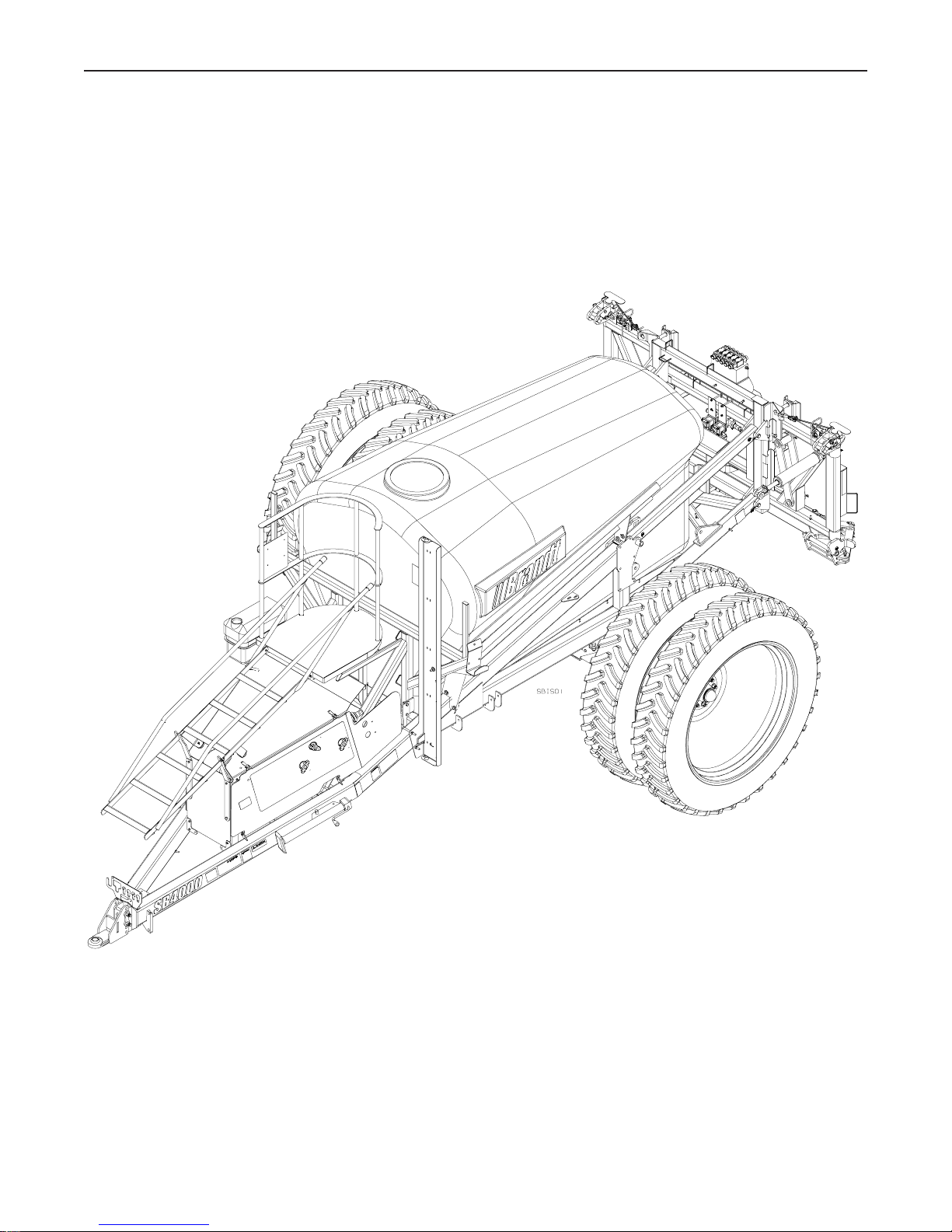
SB4000
SUSPENDED BOOM
SPRAYER
ASSEMBLY &
Part No. B012925 rev.14
PARTS MANUAL
Effective Mar., 2009

Table of Contents
Section 1: Trailer Assembly .................................................................................................................... 1
1.1 Axle Stub Assembly .............................................................................................................. 4
1.1.1 Axle Stub Assembly - Non-Suspension Trailer ............................................................4
1.1.2 Axle Stub Assembly - Suspension Trailer .................................................................... 6
1.2 Tire and Wheel Assembly ......................................................................................................7
1.2.1 Single Wheel Assembly ..............................................................................................7
1.2.2 Dual Wheel Assembly with Two Offset Rims .............................................................. 7
1.2.3 Dual Wheel Assembly with on 11” or 15” Offset Rim and one 0” Offset Rim ...............8
1. 2 Hitch Assembly ..................................................................................................................... 9
1.3 Ace Hydraulic Pump Assembly............................................................................................ 10
1.4 Hypro Hydraulic Pump Assembly ........................................................................................12
Section 2: Boom Assembly ..................................................................................................................15
2.1 Outer Boom Hinge Assembly .............................................................................................. 16
2.2 Centre Boom Assembly .......................................................................................................17
2.3 Inner Boom Assembly .........................................................................................................19
2.4 80’ Outer Boom Assembly ..................................................................................................21
2.5 90’ Outer Bomm Assembly ................................................................................................. 23
2.6 80’ & 90’ Outer Boom Tip Assembly ..................................................................................25
2.7 100’ Outer Boom Assembly ................................................................................................27
2.8 100’ Outer Boom Tip Assembly ..........................................................................................29
2.9 100’ Outer Boom Fold Hydraulic Assembly .........................................................................31
2.10 Adjusting the Pressure Relief Valve on the Hydra. Solenoid Block for the 100’ Booms.......... 34
2.11 Nozzle Body and Wind Cone Assembly ............................................................................... 35
2.11.1 Swivel Jet Nozzle Bodies ......................................................................................... 35
2.11.2 Combo Jet Nozzle Bodies ........................................................................................ 35
2.11.3 Wind Cone Trimming ............................................................................................... 36
Section 3: Manually Adjusted Rate Control Assembly .......................................................................... 37
3.1 Spray Systems Model 744 Manual Rate Controller .............................................................. 38
Section 4: Automatic Rate Controller Assembly ................................................................................... 39
4.1 Controller Characteristics .................................................................................................... 40
4.1.1 Speed Sensor ..........................................................................................................40
4.1.2 Flow Sensor ............................................................................................................ 40
4.1.3 Pressure Regulator ................................................................................................... 40
4.1.4 In-Cab Control Unit .................................................................................................41
4.2 Installation of the Controller ................................................................................................. 41
4.2.1 Flow Sensor Placement ............................................................................................41
4.2.2 Flow Sensor Installation ........................................................................................... 43
4.3 Installing the Speed Sensor and Magnets ............................................................................. 44
4.3.1 Installing the Speed Sensor for a Micro Trak 3405F & 9000 ....................................44
4.3.2 Installing the Speed Sensor for a Raven 450 Controller ............................................. 46
4.4 Installing the Electric Pressure Regulator .............................................................................. 47
4.4.1 Installing the Pressure Reg. for a Micro Trak 3405F & 9000 ........................................ 47
4.4.2 Installing the Pressure Reg. for a Raven 450 Controller ................................................. 48
4.5 In-Cab Control Unit Installation ........................................................................................... 48
Section 5: Hydraulic Boom Controls .................................................................................................... 49
5.1 Installing the Boom Control Joystick .................................................................................... 50
5.2 Adapting the Hydraulic Block for an Open Centre Hydraulic System .................................... 51
5.3 Adapting the Hydraulic Block for an Load Sensing Hydraulic System ................................... 53
Section 6: Parts ............................................................................................................................. P-1

PREDELIVERY INSPECTION
NOTE: Before unfolding the booms. Remove lock bolts from front boom rests and outer boom transport pins. Replace above for high speed long distance transport.
Assembly Completion including Options
___ Inner, Outer and Tip Booms are adjusted level. Refer to Section 6.2, 6.3 and 6.4 of Operator’s Manual for
complete adjustment procedure.
___ Inner booms are inline with the Center Boom in field position. Refer to Section 6.8 of Operator’s Manual for
complete adjustment procedure.
___ Ladder & Tip Transport Latches rotate freely. Refer to Section 6.5 and 6.6 of Operator’s Manual for complete
adjustment procedure.
___ Spray pipes rotate freely to 95 degrees with the Quick Spray Angle Kit. Refer to the Quick Spray Angle Kit
Assembly Manual for complete adjustment procedure.
___ Wheel Bolts are torqued to 325 ft.lbs.
___ Sprayers with Suspension, refer to Section 5.11 of the Operator’s Manual for checking and recharging the
Suspension Cylinder Accumulators. The Accumulators must be pressurized to 650 psi.
Function Check
___ Cycle the booms from transport to field. Refer to Section 3.6 and 3.7 of Operator’s Manual for the complete
operating procedure.
___ Hydraulic Hoses are free and all fittings are tight.
___ Chemical Lines are free and fittings are tight.
Operation Test
___ Spray System Pressure Test.
1. Fill the sprayer with water.
2. Adjust the flow to the hydraulic pump as per section 4.2 of the Operator’s Manual.
3. Start the pump.
4. Turn on the ball valves.
5. Adjust the regulating valve to achieve 90 psi to spray pipe.
6. Check for leaks.
7. Properly drain the sprayer after test. See Section 5.9 of the Operator’s Manual.
___ Sprayer Control Monitor Test.
1. Set up the Controller as per Section 3 and 4 of the Assembly manual and the Controller manual.
2. Cycle the boom ball valves on and off.
3. Cycle the master switch on and off.
4. Cycle the regulating valve open and closed.
5. Drive and check for ground speed if auto rate controller is present.
___ Foam marker Test (if present).
1. Do not fill with water.
2. Ensure both pumps start when switched to left and then to right.
___ Auto Boom Height Test (if present).
1. Set up the controller as per the NORAC Operator’s Manual.
2. Input a boom height setting of 25”.
3. Raise the entire boom to approximately 55”.
4. Turn the controller to Auto from Manual and ensure that the boom lowers to the set point.

___ Chemical Injection Test (if present).
1. Set up the controller as per the SideKick Manual.
2. Add RV antifreeze to the Chemical Injection Tank.
3. Divert the flow from inline mixer to the chemical injection tank.
4. Input a ground speed into the controller of approximately 5 mph.
5. Input an application rate into the Sidekick of 20 oz./acre.
6. Ensure that flow is circulating into tank.
___ Suspension Test (if present).
1. Start the tractor and engage the hydraulics. Make sure the tractor is out of gear and the park brake is
applied. Make sure the in-cab suspension switch is turned on.
2. Carefully crawl under the trailer.
3. While facing forward, grasp both the left and right upper micro switches and rotate them up and hold until the
hydraulic cylinders are fully extended. The trailer will rise up. Release the switches and the trailer should
return to the middle position. Watch your head!
4. Grasp both the left and right lower micro switches and rotate them down and hold until the hydraulic cylinders
are fully contracted. The trailer will drop down. Release the switches and the trailer should return to the
middle position. Watch your head!
Final Inspection
___ All Fasteners are tightened the appropriate amount.
___ Lubricate the machine. Refer to Section 5 of the Operator’s Manual.
___ Check the Tire Pressures. Refer to Table 8.4 of the Operator’s Manual.
___ Flush the plumbing system. See Section 3.11 of the Operator’s Manual for complete instructions.
___ Clean the Main Strainer and the Inline Filters (if present).
___ Torque wheel bolts. Refer to Table 8.4 of the Operator’s Manual.
___ Axle clamps bolts. Refer to Section 6.9 of the Operator’s Manual.
Safety Inspection
___ All safety and operational decals are installed and legible. Refer to Section 2.9 and 2.10 of the Operator’s
Manual.
___ Reflectors, Lights and SMV are clean and unobstructed.
___ Optional Light Package is operable (if present).
___ Light Package and Transportation reflectors comply with local highway and transport authorities regulations.
Customer Setups
___ Electrocution decal is installed in the tractor cab, near the Joystick
___ Boom Folding decal is installed in the tractor cab, near the Joystick
___ Adjust the flow to Hydraulic pump. Refer to Section 4.2 of Operator’s Manual for complete adjustment procedure.
___ Adjust the flow to Hydraulic block. Refer to Sections 3.3 and 3.5 of Operator’s Manual.
___ Adjust the hitch height. Refer to Section 6.1 of Operator’s Manual for complete adjustment procedure.
___ Review the Operator’s and Safety Instructions.
Date:_____________________ Dealer’s Signature: ________________________________________

This page is blank.

SECTION 1 - Trailer Assembly
SECTION 1
TRAILER ASSEMBLY
1
SECTION 1 - Trailer Assembly
2
SECTION 1 - Trailer Assembly
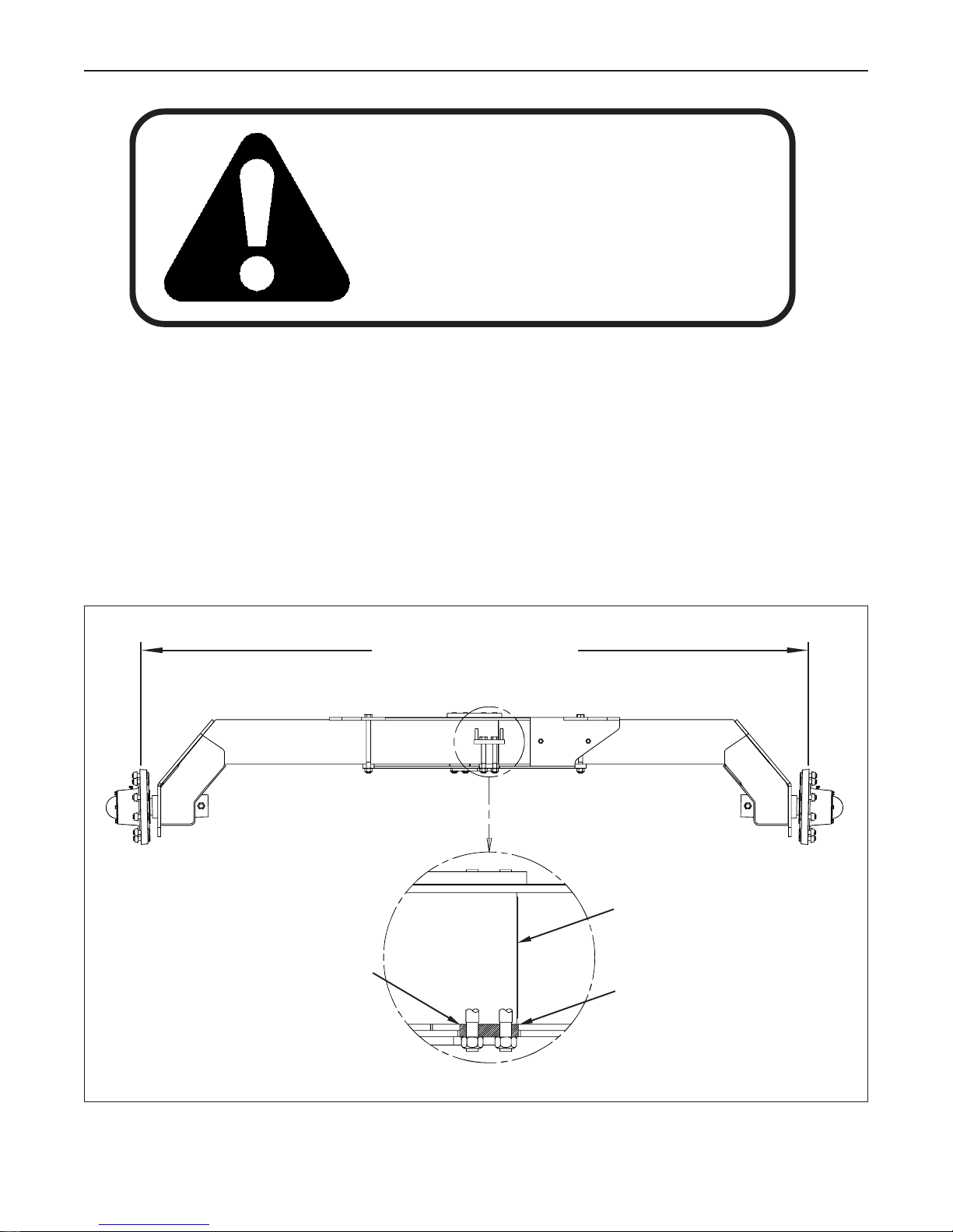
W ARNING
AXLE STUB CLAMPS
Ensure that the inner axle stub clamps are clamping the ends of
each axle stub (See figure). The end of each axle stub must at
least be in line with the outer edge of their respective clamp
before towing. Refer to Section 6.8 in the Operator’s Manual
for more details.
MAX 120” (Standard Axle)
MAX 152” (Extended Axle)
End of axle stub
Inner axle clamp
Outer edge of clamp
3
SECTION 1 - Trailer Assembly
1.1 AXLE STUB ASSEMBLY
1.1.1 Axle Stub Assembly - Non-Suspension Trailer
CAUTION! To prevent personal injury when assembling the sprayer, raise the trailer and block in place
before inserting the axle stubs. Be sure the trailer is stable before any work begins. Never
rely on a jack or hydraulic devise to support a raised implement.
The sprayer must always be connected to a tractor when the booms are in field position.
CAUTION! Always position the wheel track at the widest possible spacing which will increase the
stability of the sprayer. Only use the narrow settings when absolutely necessary. Use
extreme caution when turning corners or on hill sides when the tracking is set in the narrow
spacing. The centre of gravity of the sprayer is high when the tank is full.
Two lengths of Axle Stubs are available for the sprayer. The short stub has a wheel spacing of 72” to 120” and the
long stub has a spacing of 88” to 152”
NOTE: If the sprayer has been shipped with the Axle Stubs installed, the stub spacing MUST be adjusted. See
the warning on page 3.
1. Raise the trailer so the bottom of the axle housing is at least 43” off the ground and block in place.
2. Loosely assemble the Small Clamps to both ends of the Axle Housing using four 3/4”x 10” bolts and lock nuts,
where shown in Fig. 1.1. Just start the nuts on the bolts at this time.
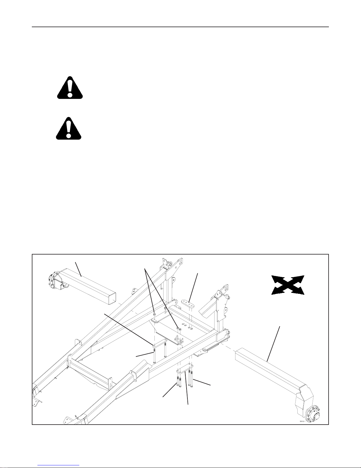
Front Right Axle Stub
3/4” Lock Nut
Small Clamp Plate
3/4”x 10” Bolt
Axle Bolt Plate
3/4”x 11” Bolt
Right
Front
Rear Left Axle Stub
Rear
Left
The Tank Saddle and part of the frame has been removed for clarity
FIG. 1.1 AXLE STUB A SSEMBLY
3/4”x 6” Bolt
Large Clamp Plate
4
SECTION 1 - Trailer Assembly
3. Mount the Large Clamp Plates to the bottom of the
Axle Housing using four 3/4”x 6” bolts and lock nuts
on the outside of the housing and four 3/4”x 11”
bolts and the Axle Bolt Plate on the inside of the
housing. Just start the bolts into the nuts at this time.
See Fig. 1.1.
4. Slide the Axle Stubs into axle housing. Make sure
the stub on the left side of the frame is in the back
portion of the housing and the stub in the right side is
in the front. Always position the wheels at the widest
possible track spacing to reduce the possibility of
tipping the sprayer.
Note: The hubs are offset on the stubs
to keep the trailer wheels inline. Make
sure the offset on the right stub is towards
the back of the trailer and the offset on
the left stub is towards the front of the
trailer.
FIG. 1.2 AXLE STUB CLAMP BOLTS
ATTENTION
5. Adjust the stubs to the desired
wheel track and clamp in place.
Example: If the wheel tracking is to
be set at 88”, adjust the stubs so
the outside of the hub flange is 44”
from the centreline of the trailer
when installing single wheels. The
duals come with 11” or 15” offsets.
Add the offset to the stub dimension
to get the proper inner dual tracking
width. To get 44” on the inner dual,
the stub must be at 55” or 59”.
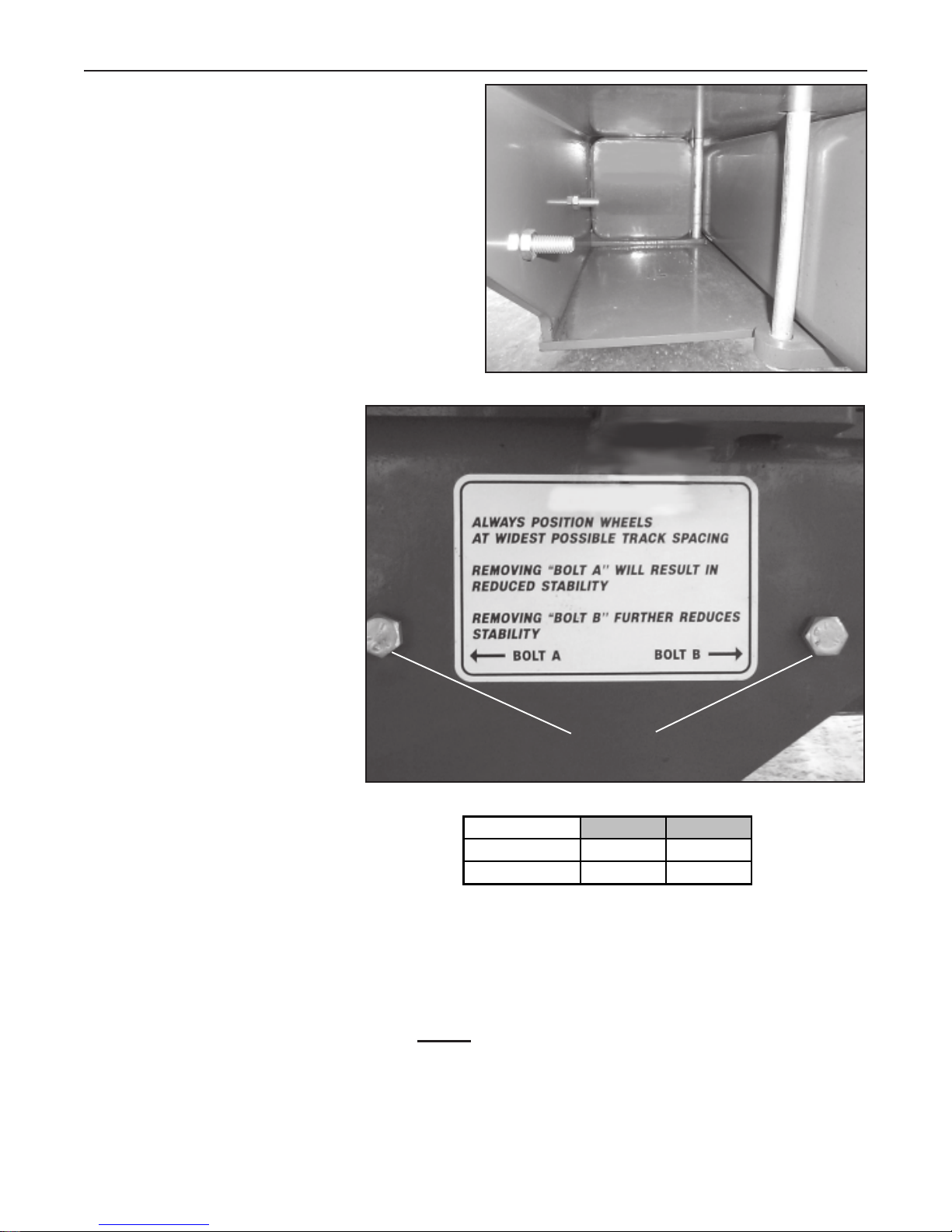
IMPORTANT: Make sure the stub is
not extended past the inner clamp in the
axle housing. See Fig. 1.2.
Note: Two stop bolts have been placed
in the axle housing to restrict the narrow tracking capability of the axle stubs. See Fig. 1.3. Going beyond these
bolts should only be done if absolutely necessary.
FIG. 1.3 AXLE STUB STOP BOLTS AND WARNING DECAL
Short Stub 105" c-c 88" c-c
Long Stub 137" c-c 120" c-c
FIG. 1.4 TRACKING WIDTHS WITH THE STUBS A GAINST THE
STOP BOLTS
Stop Bolts
Bolt A Bolt B
If the narrow track spacing must be used, you MUST slow down and/or reduce the water level in the tank to
compensate for the narrow track width. Remember, the centre of gravity of this sprayer is high when the tank is
full.
Fig. 1.4 shows the centre to centre tracking widths when the stubs are pushed against the stop bolts.
5
SECTION 1 - Trailer Assembly
1.1.2 Axle Stub Assembly - Suspension Trailer
CAUTION! To prevent personal injury when assembling the sprayer, raise the trailer and block in place
before attaching the axle stubs. Be sure the trailer is stable before any work begins.
Never rely on a jack or hydraulic devise to support a raised implement.
The sprayer must always be connected to a tractor when the booms are in field position.
CAUTION! Always position the wheel track at the widest possible spacing which will increase the
stability of the sprayer. Only use the narrow settings when absolutely necessary. Use
extreme caution when turning corners or on hill sides when the tracking is set in the narrow
spacing. The centre of gravity of the sprayer is high when the tank is full.
1. Raise the trailer so the bottom of the axle housing is at least 43” off the ground and block in place.
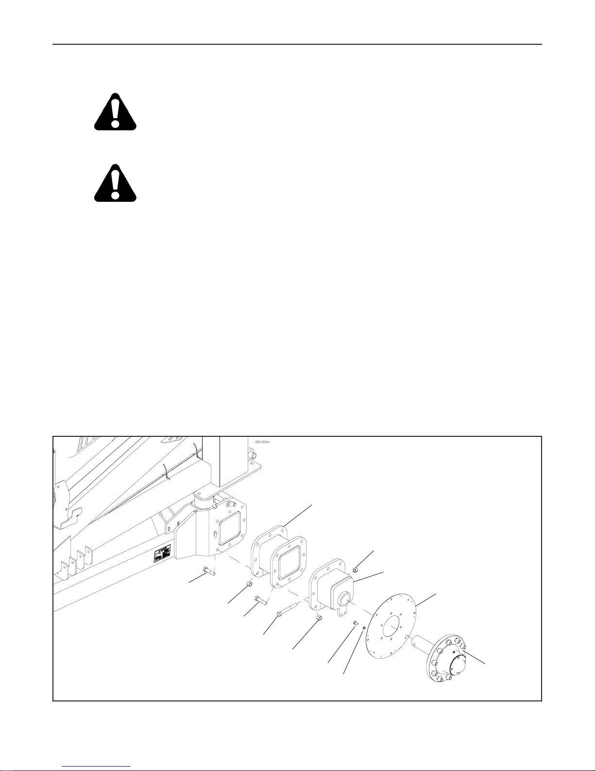
2. Install the Wheel Magnet Mount onto the back side of a Hub & Spindle Assembly using six 1/2”x 3/4” fine
thread bolts and lockwashers as shown in Fig. 1.5. This hub will be installed on the left side of the trailer.
3. Attached both Hub & Spindle Assemblies to the Axle Stubs using a 3/4”x 5” bolt and lock nut in each.
4. Attach the chosen Axle Extension to the trailer frame using eight 3/4”x 2 1/2” bolts and lock nuts. Torque the
nuts to 290 ft.lbs.
Note: If the sprayer wheels will be set at a 72” wheel track, no Axle Extensions will be used.
5. Attach the Axle Stubs to the Axle Extensions using eight 3/4”x 2 1/2” bolts and lock nuts. Torque the nuts to
290 ft.lbs.
Axle Extension
(not used if wheel track
is set to 72”)
3/4” Lock Nut
Axle Stub
3/4”x 2 1/2” Bolt
3/4” Lock Nut
Wheel Magnet Mount
3/4”x 2 1/2” Bolt
FIG. 1.5 AXLE STUB A SSEMBLY - SUSPENSION TRAILER
3/4”x 5” Bolt
3/4” Lock Nut
1/2”x 3/4” Fine Thread Bolt
1/2” Lockwasher
6
Hub & Spindle
Assembly
SECTION 1 - Trailer Assembly
1.2 TIRE AND WHEEL ASSEMBLY
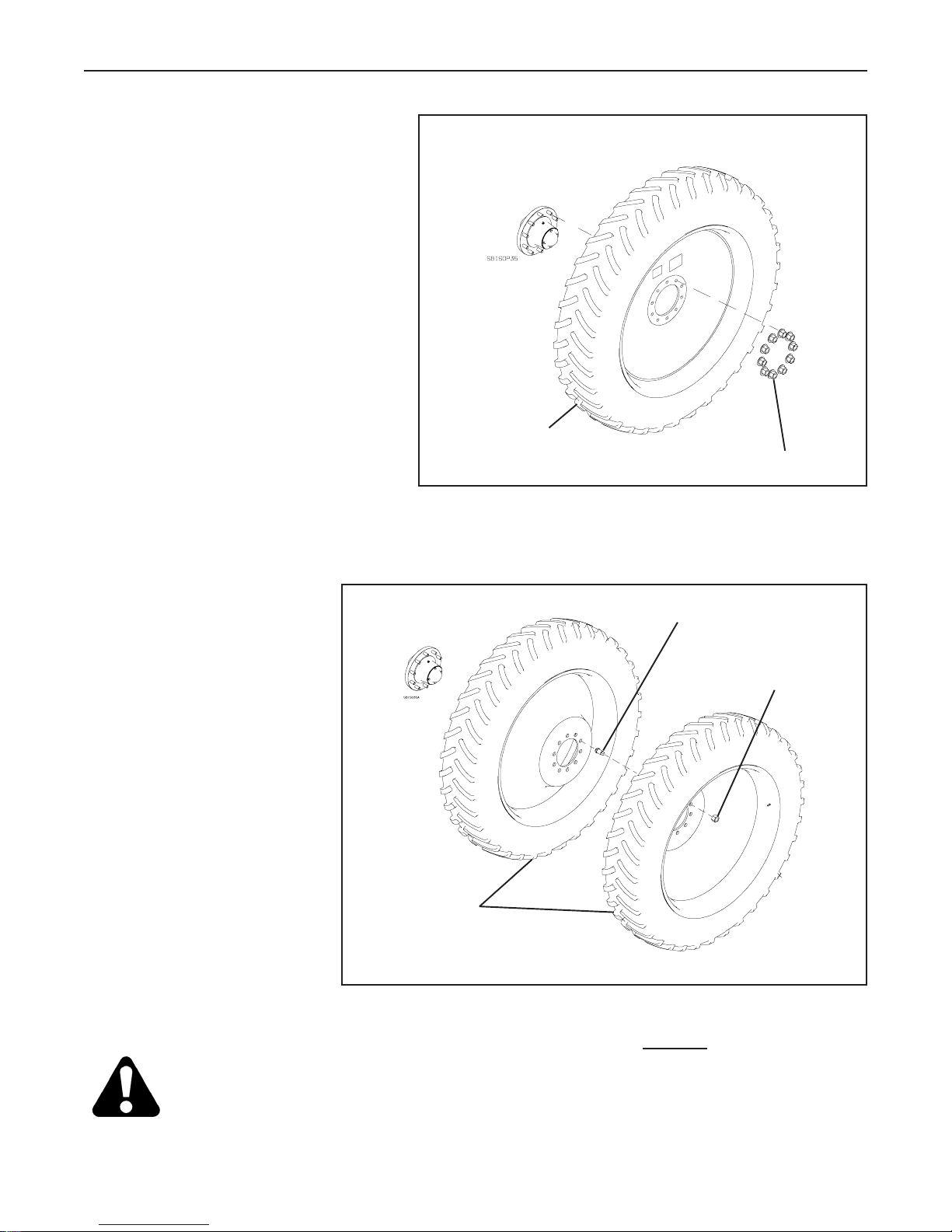
1.2.1 Single Wheel Assembly
1. Attach the tires and rims to the Axle Stub
using flange wheel nuts. Torque the nuts to
325 ft. lbs.
Note: Fig. 1.6 shows the left tire and rim
assembly.
Single Tire with
0” Offset Rim
FIG. 1.6 SINGLE WHEEL A SSEMBLY
Flange Wheel Nuts
1.2.2 Dual Wheel Assembly with two Offset Rims
1. Install the inner Tire and Wheel
assembly on the Axle Stub using
the Inner Budd Nuts. Torque
the nuts to 325 ft. lbs.
Note: Fig. 1.7 shows the left tire and
rim assembly.
2. Install the outer Tire And Rim
assembly onto the Inner Budd
Nuts and fasten in place with the
Outer Budd Nuts. Torque the
nuts to 325 ft. lbs.
Dual Tires with
11” or 15” Offset Rims
FIG. 1.7 DUAL WHEEL A SSEMBLY WITH TWO OFFSET RIMS
Inner Budd Nut
Outer Budd Nut
CAUTION If two offset dual wheels are being mounted on the sprayer, NEVER run the sprayer with
one of the duals removed from each side. Severe damage to the hub and spindle could
occur. Single tires must have the 0” offset rims.
7
SECTION 1 - Trailer Assembly
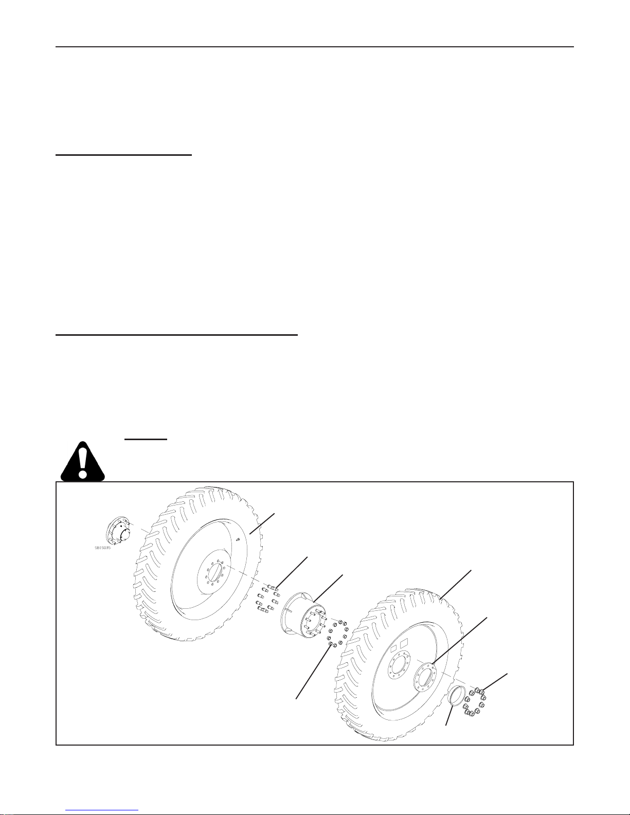
1.2.3 380/85 R46 Dual Wheel Assembly with one 11” or 15” Offset Rim and one
0” Offset Rim
With this wheel package, the machine can be converted from dual wheels to single wheels using the existing tires
and rims.
Dual Wheel Assembly
1. Install the 11” or 15” Offset Tire and Wheel assembly on the Axle Stub using the Inner Budd Nuts. Torque the
nuts to 325 ft. lbs.
Note: Fig. 1.8 shows the left tire and rim assembly.
2. Install the Dual Offset Adapter onto the Inner Budd Nuts and fasten in place with the Outer Budd Nuts.
Torque the nuts to 325 ft. lbs.
3. Mount the 0” Offset Tire and Rim Assembly onto the adapter using the Dual Adapter Clamp Plate and the
flange wheel nuts. Torque the nuts to 325 ft. lbs.
Converting the Dual Wheels to Singles
1. Remove the Outer Tire and Rim assembly. Remove the Dual Offset Adapter from the Inner Tire and Rim and
remove Inner Tire and Rim assembly.
2. Install the Outer Tire and Rim assembly (rim with the 0” offset) on the Axle Stub using the flange wheel nuts as
shown in Fig. 1.6.
CAUTION NEVER run the sprayer with Tires and 11” or 15” offset Rims as singles. Severe damage
to the hub and spindle could occur. Single tires must have the 0” offset rims.
Tire with 11” or 15”
Offset Rim
Inner Budd Nut
Dual Offset Adapter
Tire with 0” Offset Rim
Dual Adapter
Clamp Plate
Flange Wheel Nuts
FIG. 1.8 DUAL WHEEL A SSEMBLY WITH ONE 11” OR 15” OFFSET RIM AND ONE 0” OFFSET RIM
Outer Budd Nut
Plastic Cap
8
SECTION 1 - Trailer Assembly
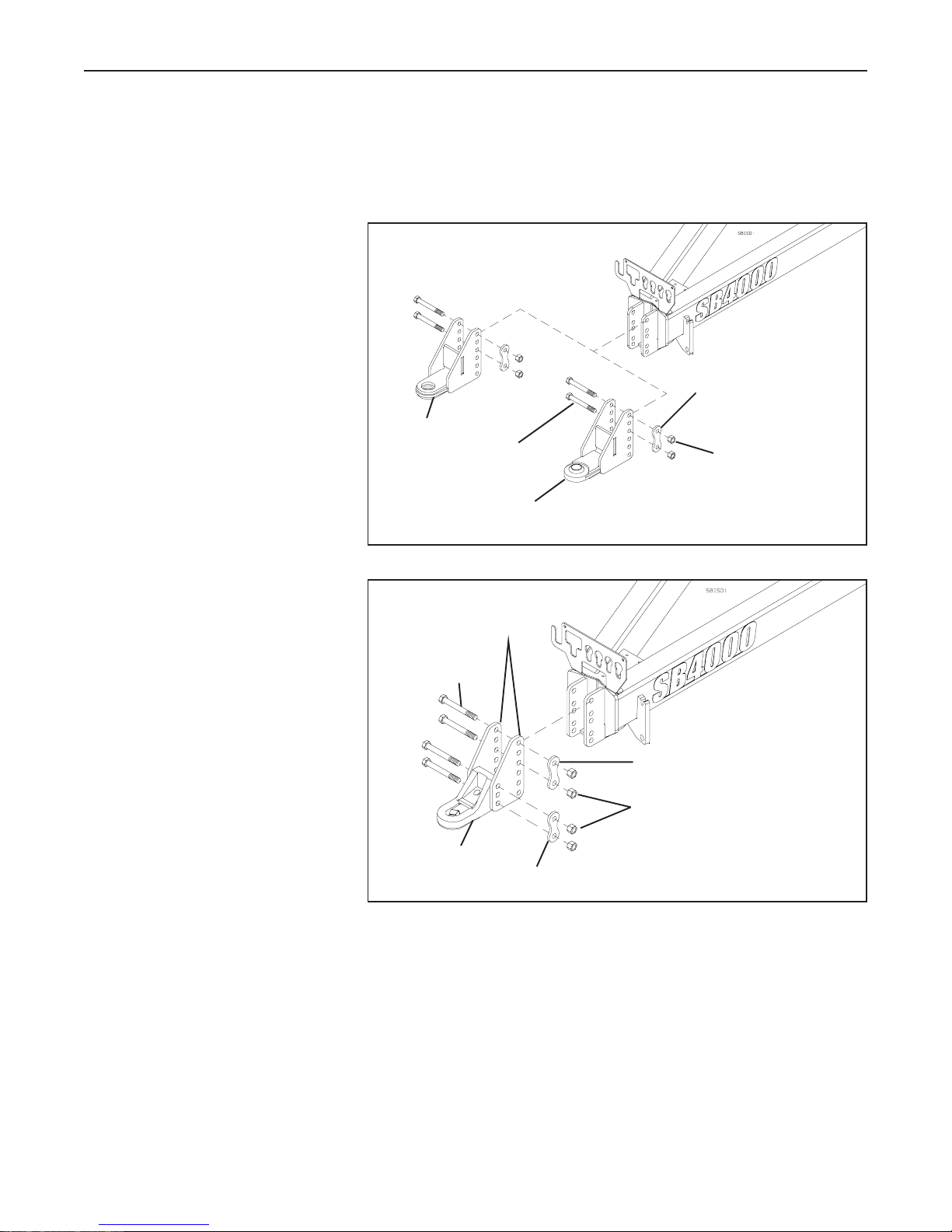
1.3 HITCH ASSEMBLY
Three different hitch styles are available for the SB4000 sprayer. Fig. 1.9 and 1.10 show the different styles. It is
recommended that the Ball Socket style hitch be used when the Auto Boom Height Control option is installed on
the sprayer. Make sure to use the spacers provided with the hitch, between the ball socket and the tractor hitch to
reduce the vertical movement of the
sprayer hitch. See Fig. 3.9 of the
Operator’s manual.
1. With the sprayer trailer parked on a
level piece of ground, adjust the
trailer level using the implement jack.
2. With the trailer level, back the
tractor, that will be pulling the
sprayer, close to the sprayer hitch.
3. Install the hitch on the sprayer frame
as shown in Fig. 1.9 and 1.10. The
Plate Hitch and the Ball Socket
Hitch mount to the frame using two
3/4”x 7” bolts, the Hitch Bolt Spacer
and lock nuts. The Bolt Spacer must
be mounted on the threaded end of
the bolts. Adjust the hitch to match
as closely to the tractor hitch as
possible and secure in place.
4. The Perfect Hitch comes with two
separate plates which hold the
Perfect Hitch to the sprayer frame.
See Fig. 1.10. Loosely attach the
Perfect Hitch to the two plates using
two 3/4”x 7” bolts, the Perfect Hitch
Bolt Spacer (the spacer with the
holes 3” c-c) and lock nuts. Make
sure the bolt spacer is on the
threaded end of the bolts. Slide the
plates onto the sprayer hitch, adjust
the hitch to match as closely to the tractor hitch as possible and secure in place with two 3/4”x 7” bolts, the
Hitch Bolt Spacer and lock nuts. Tighten all four of the hitch bolts.
Plate Hitch
3/4”x 7” Bolt
Ball Socket Hitch
FIG. 1.9 PLATE OR BALL SOCKET HITCH A SSEMBLY
Perfect Hitch Plate
3/4”x 7” Bolt
Long Hitch Bolt Spacer
3/4” Lock Nut
Perfect Hitch
Perfect Hitch Bolt Spacer
FIG. 1.10 PERFECT HITCH ASSEMBLY
Hitch Bolt Spacer
3/4” Lock Nut
NOTE: The Perfect Hitch can be mounted as shown in Fig. 1.10 or flipped 180o, which ever works best for the
tractor.
5. Adjust the tongue of the Perfect Hitch to the draw pin which will be used, by loosening the bolt in the hitch,
adjusting the tongue to the draw pin and retightening the hitch bolt. This will need adjustment from time to time.
9
SECTION 1 - Trailer Assembly
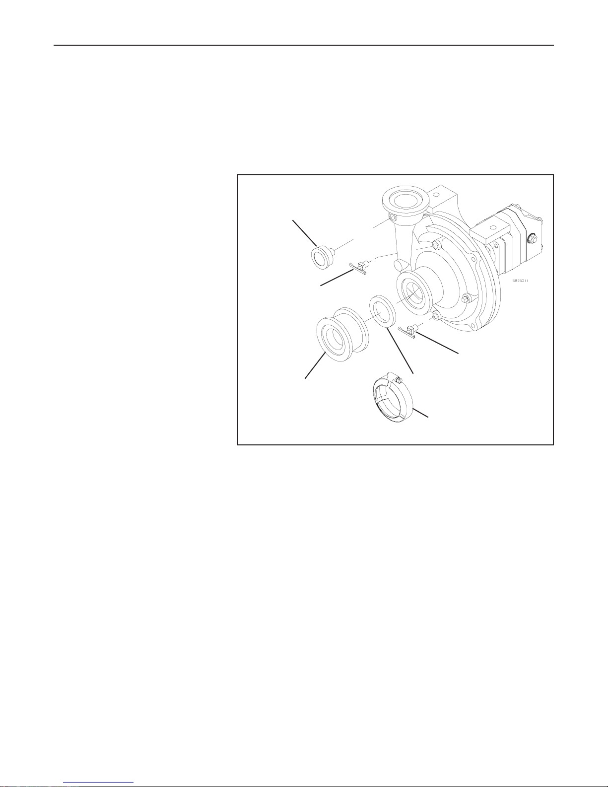
1.4 ACE HYDRAULIC PUMP ASSEMBLY
Two Ace hydraulic pumps are available for the SB4000 sprayer. The model FMC-150-HYD-206 is the pump
that will be used for most applications. The model FMC-200-HYD-310 is available for tractors with large
capacity open centre hydraulic systems. Refer to Section 3.3 of the Operator’s manual for the hydraulic requirements
for both pumps.
1. Install the 2” Full Port x 2” Std. Port Flange Adapter to the pump using a 2” Std. Flange Gasket and clamp as
shown in Fig. 1.11.
2. Remove the 1/8” pipe plug from the
discharge port of the pump and install
the 1 1/2” gauge. Use thread sealant
or teflon tape on the threads. If the
Guage Kit has or is being installed
on the sprayer, install the 1/8” MPT
x 1/4” Hose Barb fitting in place of
the 1 1/2” guage.
3. Remove the top and bottom 1/8”
pipe plugs from the pump and install
the two 1/8” drain cocks. Use
thread sealant or teflon tape on the
threads.
IMPORTANT: Refer to Section 4.2.1
in the Sprayer Operators manual or
the mounting instructions included
with the pump to see if the Flow
Limiter or the Restrictor Orifice is
required for the hydraulic system in the tractor that will be used on the sprayer.
Pressure
Gauge
1/8” Drain Cock
2” Full Port x 2” Std. Port
Flange Adapter
FIG. 1.11 ACE PUMP A SSEMBLY
1/8” Drain Cock
2” Full Port Flange Gasket
2” Full Port Flange Clamp
IMPORTANT: If the tractor which will be used has open centre hydraulics, the Open Centre Tractor Hydraulic
Kit (part no. C005974) must be installed on the sprayer. Refer to the instructions included with the kit or
Section 5.2 of this manual for installation and operation.
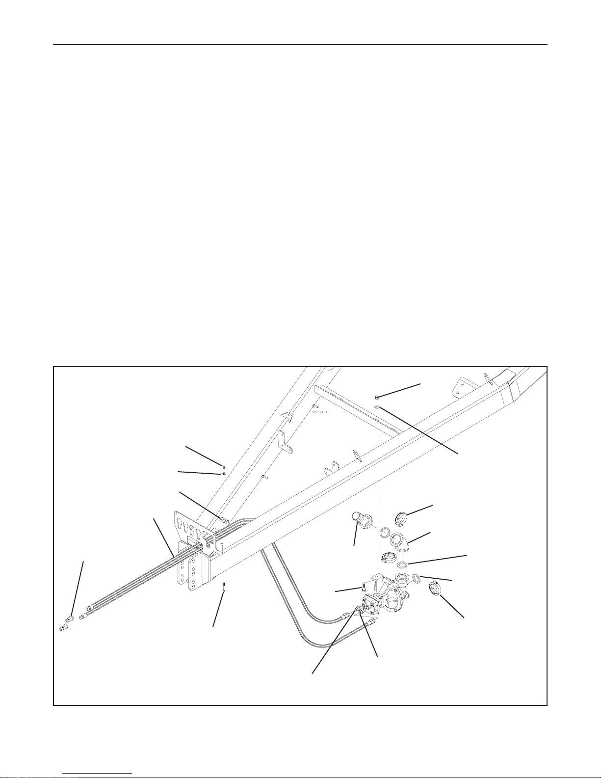
4. Remove the plastic caps from the hydraulic motor and install the hydraulic fittings as shown in Fig. 1.12. Use
pipe sealant or teflon tape on the threads. Connect the hydraulic hoses to the fittings and install the Pioneer tips
on the ends using pipe sealant or teflon tape.
5. Mount the 2”Flange Elbow x 45o onto the Pump Discharge fitting using a 2” Gasket and Plumbing Clamp. Do
not tighten the clamp yet.
6. Mount the 2” Flange x 1 1/2” Hose Barb fitting onto the elbow using a 2” Gasket and Plumbing Clamp. Do not
tighten yet.
10

SECTION 1 - Trailer Assembly
7. Loosely mount the pump assembly to the frame mount using two 3/8”x 1 1/2” bolts, flat washers and lock nuts.
Do not tighten at this time.
8. Connect the Pump to the Inlet Plumbing assembly using a 2” Full Port Gasket and Plumbing Clamp. Tighten
this clamp and tighten the pump mounting bolts.
9. Slide the hose which connects to the Line Strainer onto the 1 1/2” hose barb on the discharge of the pump.
You might have to rotate the elbow slightly to get the hose to fit properly. Clamp the hose in place and tighten
the clamps on the elbow.
10. Close the plumbing door. From under the sprayer, check the hose. Readjust the Abrasion Guard on the hose,
if necessary.
11. Route the hydraulic hoses through the hole in the hose tray (mounted under the hitch arm) and attach them to
the frame using a plastic hose holder, a 3/8”x 2” bolt, flat washer and lock nut in two locations at the hitch.
3/8” Lock Nut
3/8” Lock Nut
3/8” Flatwasher
1/2” Hydra. Hoses
Pioneer Tip
3/8”x 2” Bolt
3/8” MPT x #8 MJIC Adapter
FIG. 1.12 ACE PUMP A SSEMBLY MOUNTING
2” Flange x
1 1/2” Hose Barb
3/8”x 1 1/2”
Bolt
3/8” Flatwasher
2” Std. Clamp
2” Flange Elbow x 45
2” Std. Gasket
2” Std. Gasket
2” Std. Clamp
3/8” MPT x #8 MJIC Elbow
o
11
SECTION 1 - Trailer Assembly
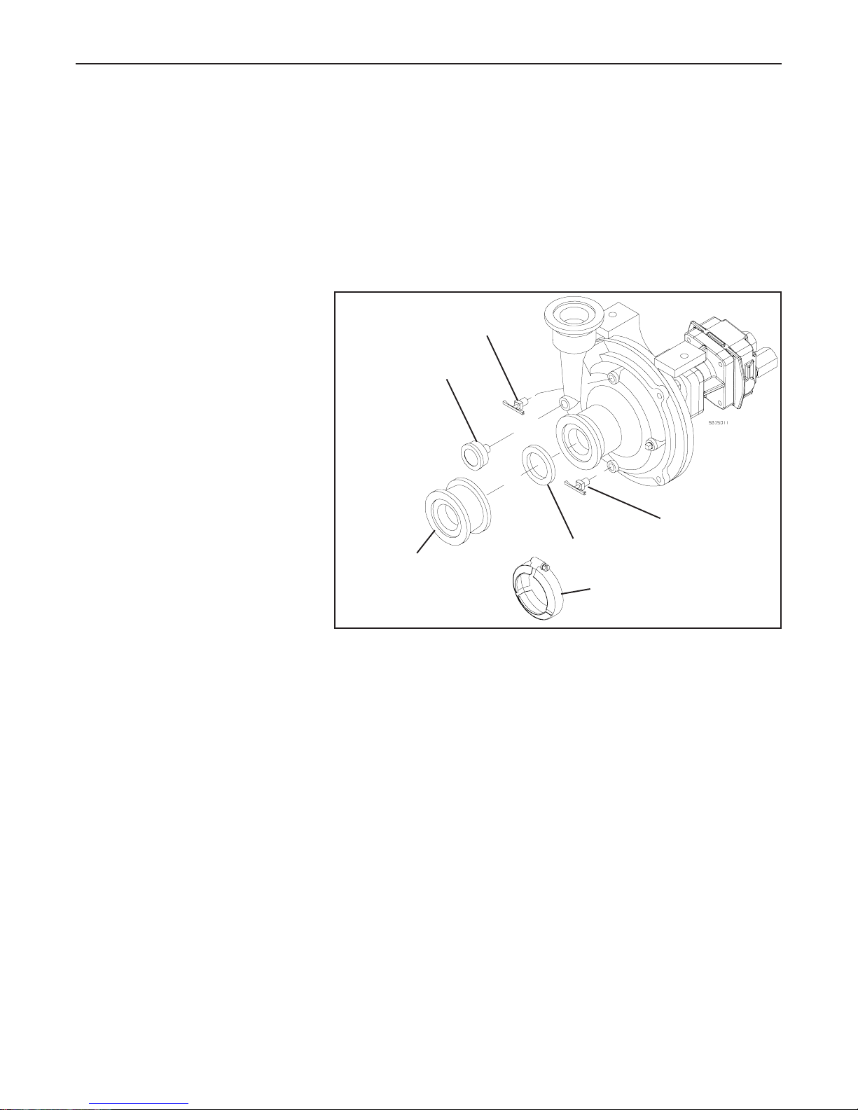
1.5 HYPRO HYDRAULIC PUMP ASSEMBLY
Two Hypro hydraulic pumps are available for the SB4000 sprayer. The model 93073 HM4C is the pump that will
be used for most lower output hydraulic systems. The model 93074 HM1C is available for tractors with high
output hydraulic systems. Refer to Section 3.3 of the Operator’s manual for the hydraulic requirements for both
pumps.
1. Remove the 1/8” pipe plug from the discharge port of the pump and install the 1 1/2” gauge. Use thread
sealant or teflon tape on the threads. See Fig. 1.13. If the Guage Kit has or is being installed on the sprayer,
install the 1/8” MPT x 1/4” Hose Barb fitting in place of the 1 1/2” guage.
2. Remove the top and bottom 1/8”
pipe plugs from the pump and install
the two 1/8” drain cocks. Use
thread sealant or teflon tape on the
threads.
IMPORTANT: Refer to Section 4.2.2
in the Sprayer Operators manual or
the mounting instructions included
with the pump to see if the Restrictor
Orifice is required for the hydraulic
system in the tractor that will be used
on the sprayer.
3. Install the 2” Full Port x 2” Std. Port
Flange Adapter to the pump using a
2” Full Port Flange Gasket and
clamp.
2” Full Port x 2” Std. Port
Flange Adapter
FIG. 1.13 HYPRO PUMP A SSEMBLY
1/8” Drain Cock
Pressure
Gauge
1/8” Drain Cock
2” Full Port Flange Gasket
2” Full Port Flange Clamp
IMPORTANT: If the tractor which will be used has open centre hydraulics, the Open Centre Tractor Hydraulic
Kit (part no. C005974) must be installed on the sprayer. Refer to the instructions included with the kit or
Section 5.2 of this manual for installation and operation.
Note: If the tractor which will be used has open centre hydraulics and you are installing a new Hypro sprayer
pump, check the inlet port of the hydraulic motor to see if a restrictor orifice has been installed at the factory.
To check this, remove the pressure port adapter from the motor and look inside it. If the restrictor has been
installed, remove it by popping it back out of the adapter.
4. Remove the plastic caps from the hydraulic motor and install the hydraulic fittings as shown in Fig. 1.14.
Connect the hydraulic hoses to the fittings and install the Pioneer tips on the ends using pipe sealant or teflon
tape.
NOTE: Before connecting the hoses, refer to section 4.2.2 of the Operator’s manual or the manual included with
the pump. Some tractors with Closed Centre Pressure Compensating hydraulics might require a restrictor
orifice to be installed in the inlet of the pump. If this is necessary, use the #8 MORB x #10 FORB orifice holder
(included with the pump) in the pump and the additional #10 MORB x #8 MJIC fitting to connect the hose.
12
SECTION 1 - Trailer Assembly
5. Mount the 2” Flange Elbow onto the Pump Discharge fitting using a 2” Gasket and Plumbing Clamp. Do not
tighten the clamp yet.
6. Mount the 2” Flange x 1 1/2” Hose Barb fitting onto the elbow using a 2” Gasket and Plumbing Clamp. Do not
tighten yet.
7. Loosely mount the pump assembly to the frame mount using two 3/8”x 1 1/2” bolts, flat washers and lock nuts.
Do not tighten at this time.
8. Connect the Pump to the Inlet Plumbing assembly using a 2” Gasket and Plumbing Clamp. Tighten this clamp
and tighten the pump mounting bolts.
9. Slide the hose which connects to the Line Strainer onto the 1 1/2” hose barb on the discharge of the pump.
You might have to rotate the elbow slightly to get the hose to fit properly. Clamp the hose in place and tighten
the clamps on the elbow.
10. Close the plumbing door. From under the sprayer, check the hose. Readjust the Abrasion Guard on the hose,
if necessary.
11. Route the hydraulic hoses through the hole in the hose tray (mounted under the hitch arm) and attach them to
the frame using a plastic hose holder, a 3/8”x 2” bolt, flat washer and lock nut in two locations at the hitch.
3/8” Lock Nut
3/8” Flatwasher
Plastic Hose Holder
1/2” Hydra. Hoses
Pioneer Tip
3/8”x 2” Bolt
2” Flange x
1 1/2” Hose Barb
3/8”x 1 1/2”
Bolt
3/8” Lock Nut
2” Std. Clamp
2” Flange Elbow x 45
2” Std. Clamp
3/8” Flatwasher
o
2” Std. Gasket
2” Std. Gasket
FIG. 1.14 HYPRO PUMP A SSEMBLY MOUNTING
#10 MORB x #8 MJIC Adapter
(Tank Port)
13
#8 MORB x #8 MJIC Adapter
(Pressure Port)

SECTION 1 - Trailer Assembly
14

SECTION 2 - Boom Assembly
SECTION 2
BOOM ASSEMBLY
15
SECTION 2 - Boom Assembly
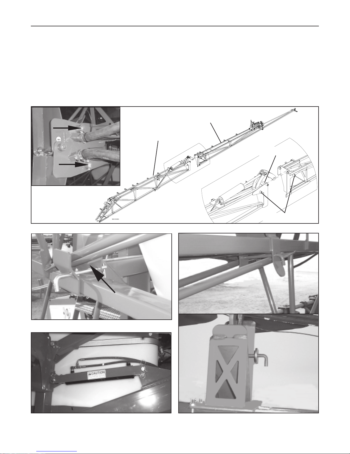
2.1 Outer Boom Hinge Assembly
1. Install the Outer Fold Linkage Pins in the Inner and Outer Booms as shown in Fig. 2.1. Make sure the pins go
through the Linkage Plates. Secure the pins in place using 3/8”x 2” bolts and lock nuts. If you are assembling
a sprayer with a 100’ boom, do not tighten these bolts.
2. Remove the Outer Boom Retaining Pins, which are in the Boom Rests (see Fig. 2.2), the Lift Cylinder
Transport Plates (see Fig. 2.3) and the Boom Transport Pins (see Fig. 2.4). Unfold the booms as per the
instructions in Section 3.6 of the Operator’s manual.
Outer Boom Assembly
Inner Boom Assembly
Outer Fold Hinge Pin
Outer Fold Linkage Pins
Fig. 2.1 Outer Fold Linkage Pins
Fig. 2.2 Outer Boom Retaining Pins
Outer Fold Linkage Pins
Fig. 2.2 Outer Boom Retaining Pin
80’ & 90’ Booms
Fig. 2.3 Lift Cylinder Transport Plate Fig. 2.4 Boom Transport Pin
100’ Boom
16

SECTION 2 - Boom Assembly
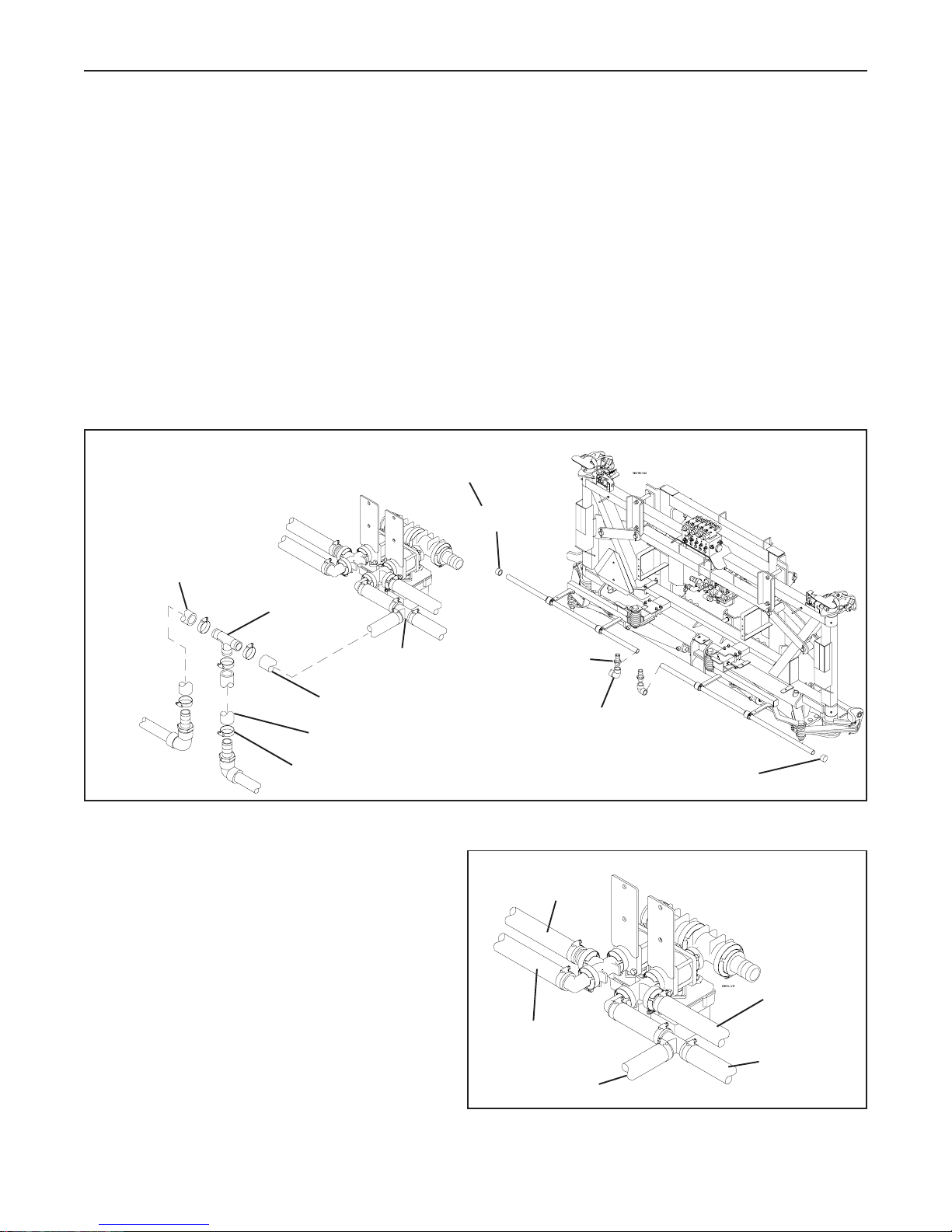
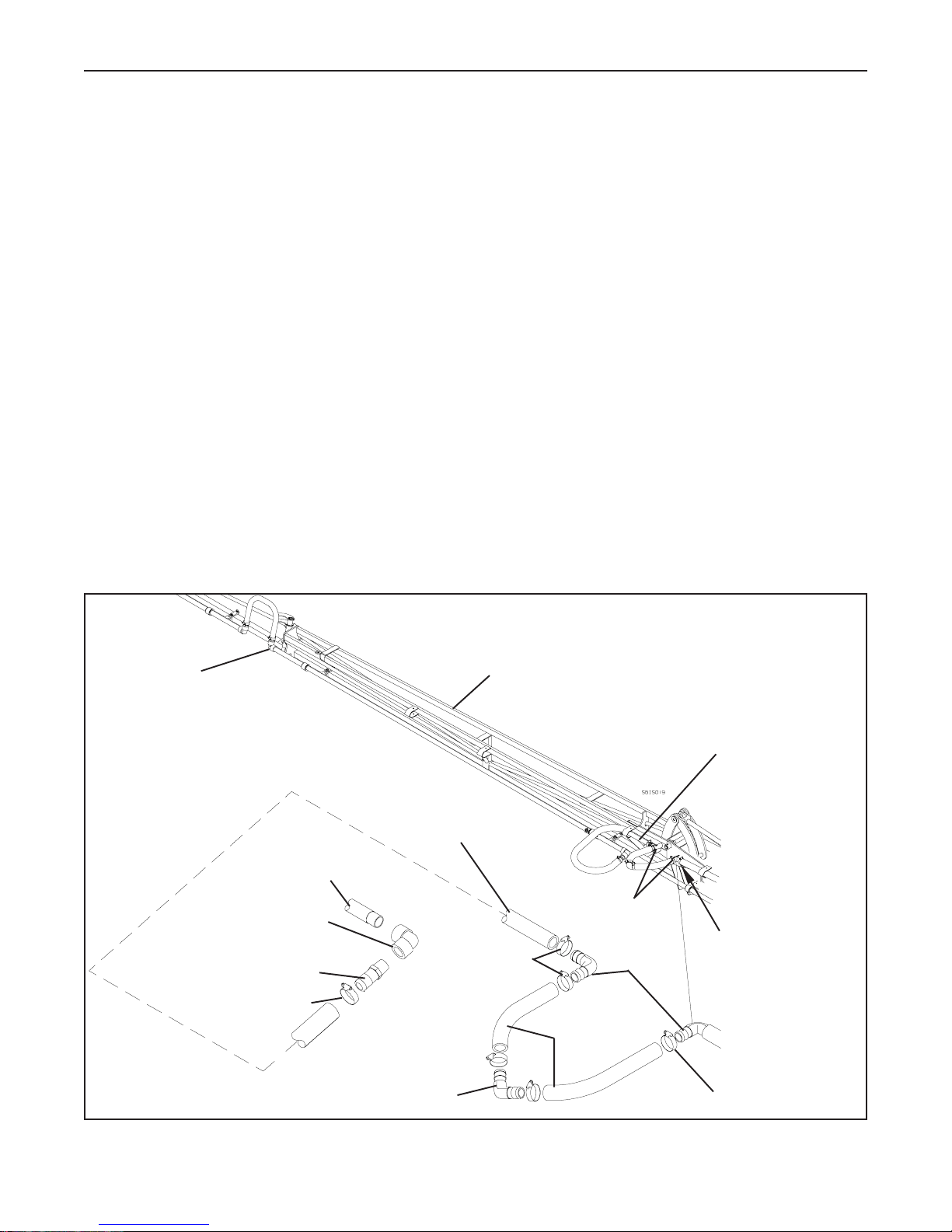
2.2 Centre Boom Assembly
1. Slide two 50” spray pipes into the struts. Position them so the outside end is 13 3/8” away from the boom
strut. See Fig. 2.5. Take note of the holes in the spray pipes and position them as shown.
2. Loosely assemble the Spray Pipe Clamps onto the spray pipes using four 5/16”x 1” bolts and lock nuts as
shown in Fig. 2.5. The Pipe Clamp Strap mounts to the boom strut with a 3/8”x 1” bolt, flatwasher and lock
nut. The other end is attached between one set of the Spray Pipe Clamps.
Note: If the Quick Spray Angle Kit will be installed on the sprayer, move the Spray Pipe Clamps to the struts
shown. Do not mount the Pipe Clamp Strap.
3. Measure the distance between the inner holes in both spray pipes and adjust this distance to 20”. Make sure
the nozzle holes in both spray pipes are inline with each other. Tighten the spray pipe clamps.
4. Thread the 1” FPT Elbows onto the spray pipes as shown in Fig. 2.6. Make sure the holes in the spray pipe
are pointing straight down and the tee is pointing up. Use pipe sealant on the fitting.
5. Screw the 1” MPT x 1 1/4” HB Fittings into the elbows. Use pipe sealant on the threads.
Top View of the Centre Boom
13 3/8” 13 3/8”
4” 4”
50”
20”
6”
6”
50”
If the Quick Spray Angle Kit will be
5/16”x 1” Bolt
Wrap friction tape around
pipe, under both clamps
Spray Pipe Clamp
installed, mount the spray pipe
clamps on the Inner Struts.
3/8”x 1” Bolt
3/8” Flatwasher
Pipe Clamp Strap
5/16” Lock Nut
Fig. 2.5 Centre Boom Spray Pipe Mounting
3/8” Lock Nut
17
SECTION 2 - Boom Assembly
6. Attach a 1 1/4” ID Hose x 17” to each the hose barbs on the spray pipes. Secure in place using 1 1/2” Hose
Clamps.
7. Install the loose ends of the hose in the 1 1/4” Hose Barb Tee as shown in Fig. 2.6. Secure in place using
1 1/2” Hose Clamps.
8. Connect the Tee fitting in the hose from the right electric ball valve to the hose barb tee fitting from the spray
pipes using the 1 1/4” ID Hose x 27” and two 1 1/2” Hose Clamps. See Fig. 2.6 & 2.7 for the spray hose
locations.
9. Thread a 1” FPT Cap onto the open ends of the spray pipes. If the Frost kit is being installed on the sprayer,
install 1” Ball Valves instead of the caps as shown in Fig. 2.6.
Replace this Caps with Ball Valves
if the Frost Kit is installed
1 1/4” ID Hose x 17”
1 1/4” HB Tee
1 1/4” HB Tee
1 1/4” ID Hose x 27”
1 1/4” ID Hose x 17”
1 1/2” Hose Clamp
Fig. 2.6 Centre Boom Plumbing Assembly
1” FPT Cap
1” MPT x 1 1/4”
Hose Barb Insert
1” FPT Elbow
1” FPT Cap
To Left
Outer Boom
To Left Inner Boom
To Centre Boom
Fig. 2.7 Spray Hose Locations
18
To Right
Outer Boom
To Right
Inner Boom
SECTION 2 - Boom Assembly
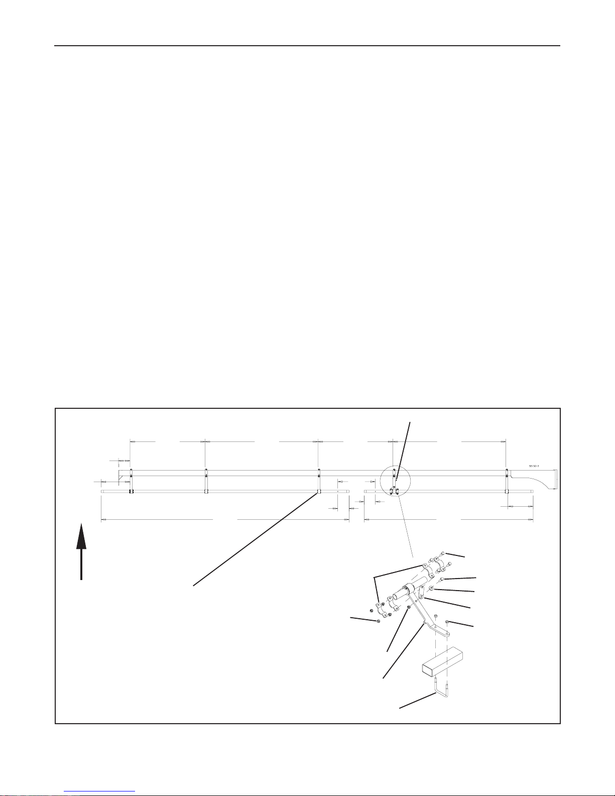
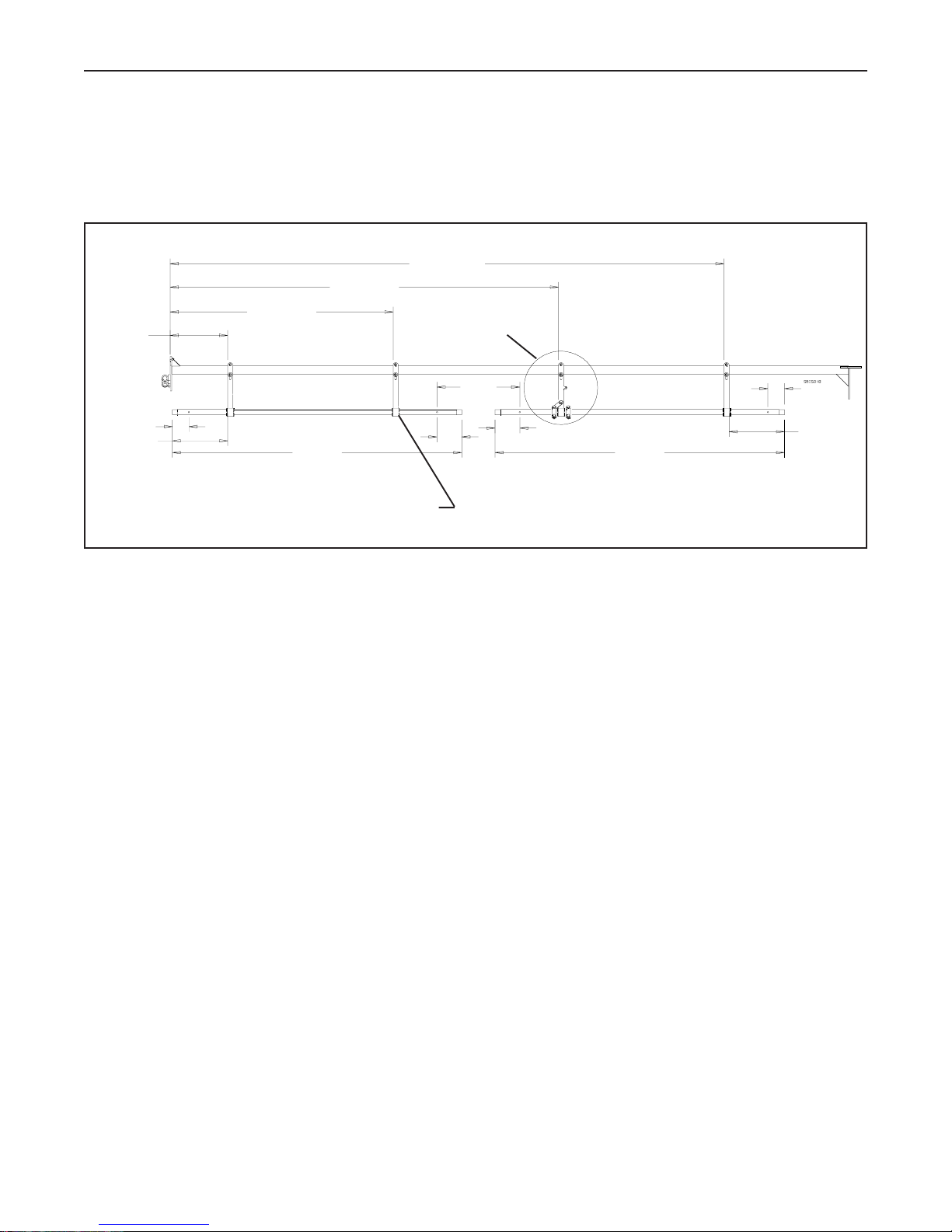
2.3 Inner Boom Assembly
1. Mount four of the regular Short Boom Struts and one of the Short Struts with the tab on the side to the lower
tube on the Inner Boom using a 3/8”x 3” Sq. U-bolt, flatwasher and two lock nuts for each. Position the struts
as shown in Fig. 2.8. Four extra Boom Struts are required if Poly Spray Pipes are being used. The extra struts
are shown as dashed lines in Fig. 2.8.
2. Slide the 90” and 132” spray pipes into the struts. Position them as shown in Fig. 2.8. Take note of the holes
in the spray pipes and position them as shown.
3. Loosely assemble the Spray Pipe Clamps onto the 90” spray pipe using four 5/16”x 1” bolts and lock nuts as
shown in Fig. 2.8. The Pipe Clamp Strap mounts to the boom strut with a 3/8”x 1” bolt, flatwasher and lock
nut. The other end is attached between one set of the Spray Pipe Clamps.
Note: If the Quick Spray Angle Kit will be installed on the sprayer, move the Spray Pipe Clamps to the strut
shown. Do not mount the Pipe Clamp Strap.
4. Thread the 1” FPT Tee onto the 90” spray pipe as shown in Fig. 2.9. Make sure the holes in the spray pipe are
pointing straight down and the tee is pointing up. Use pipe sealant on the fitting.
5. Screw the 1” MPT x 1 1/4” HB Fittings into the tee. Use pipe sealant on the threads.
40”
Top View of the Left Inner Boom
60” 60”
40”
Strut with the Tab
6 1/8”
15 3/8”
132”
6”
20”
6”
90”
Spray Pipe Clamp
Front
If the Quick Spray Angle Kit
will be installed, mount the
Spray Pipe Clamps here
5/16” Lock Nut
13 3/8”
5/16”x 1” Bolt
3/8”x 1” Bolt
3/8” Flatwasher
Pipe Clamp Strap
3/8” Lock Nut
Fig. 2.8 Inner Spray Pipe Mounting
3/8” Lock Nut
Inner Strut Assembly
3/8”x 3” Sq. U-bolt x 3”
19
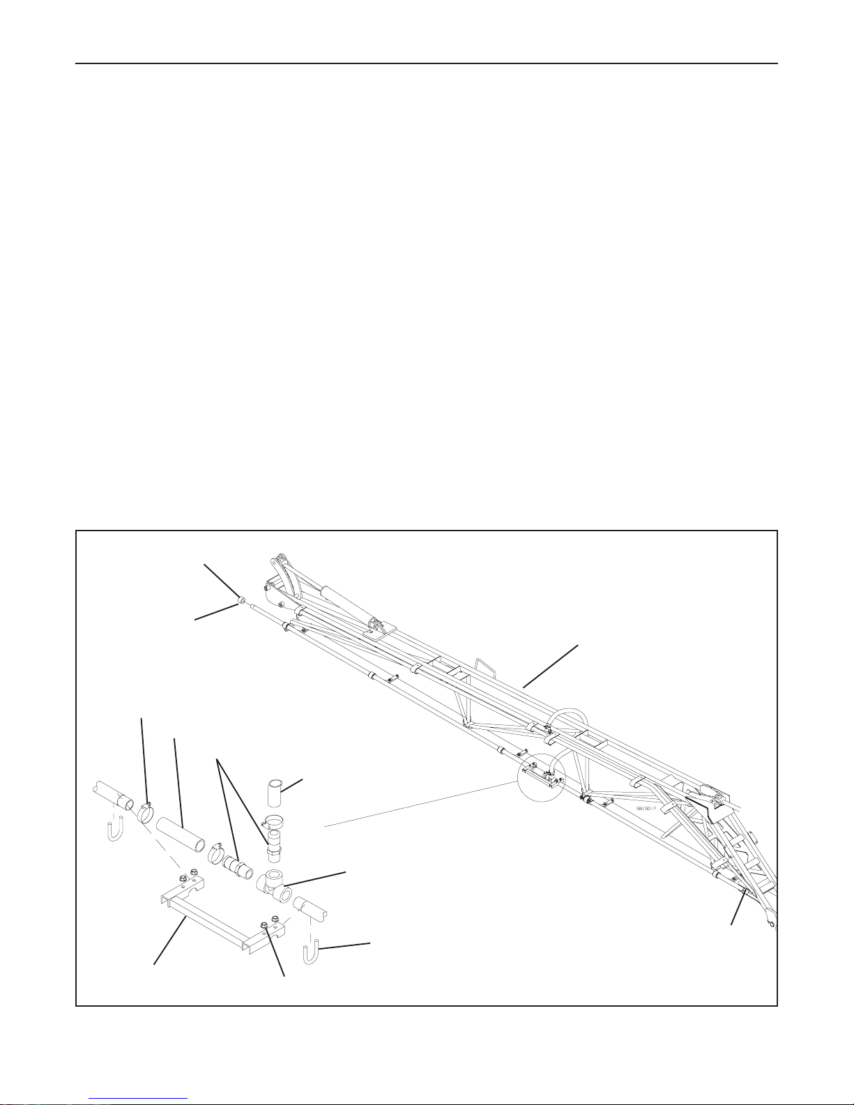
SECTION 2 - Boom Assembly
6. Slide the 1 1/4” ID x 6” hose onto the hose barb that is inline with the spray pipes. Slip the other end onto the
left spray pipe. Make sure the holes in the pipe are pointing straight down. Secure the hose to the spray pipes
using two 1 1/2” Hose Clamps. Do not tighten the clamps yet.
7. Measure the distance between the inner holes in both spray pipes and adjust this distance to 20”. Make sure
the nozzle holes in both spray pipes are inline with each other. Tighten the hose clamps.
8. Attach the Pipe Joiner to both spray pipes using two 5/16” x 1 3/8” U-bolts and flange lock nuts. Tighten the
bolts on the spray pipe clamps which position the spray pipes. Tighten the screws in the plastic spray pipe
bushings so they are clamped to the spray pipes. Do not overtighten the screws.
9. Thread a 1” FPT Cap onto the open ends of the spray pipes. If the Frost kit is being installed on the sprayer,
install a 1” Ball Valve instead of the cap where shown in Fig. 2.9.
10. Connect the hose from the left electric ball valve to the hose barb fitting on the spray pipe using a 1 1/2” Hose
Clamp. See Fig. 2.7 for the spray hose locations.
11. If the Quick Spray Angle kit has been installed, rotate the spray pipes 95o to make sure the hoses do not bind.
Make any necessary adjustments.
12. Repeat steps 1 through 10 on the Right Inner Boom.
1” FPT Cap
Replace this cap with
the Ball Valve if the Frost
Kit is installed
1 1/2” Hose Clamp
1 1/4” ID Hose x 6”
1” MPT x 1 1/4” HB Insert
To the Left Electric
Ball Valve
1” FPT Tee
Left Inner Boom
Pipe Joiner
5/16” Flange Lock Nut
Fig. 2.9 Inner Boom Plumbing Assembly
5/16” x 1 3/8” U-Bolt
20
1” FPT Cap
SECTION 2 - Boom Assembly
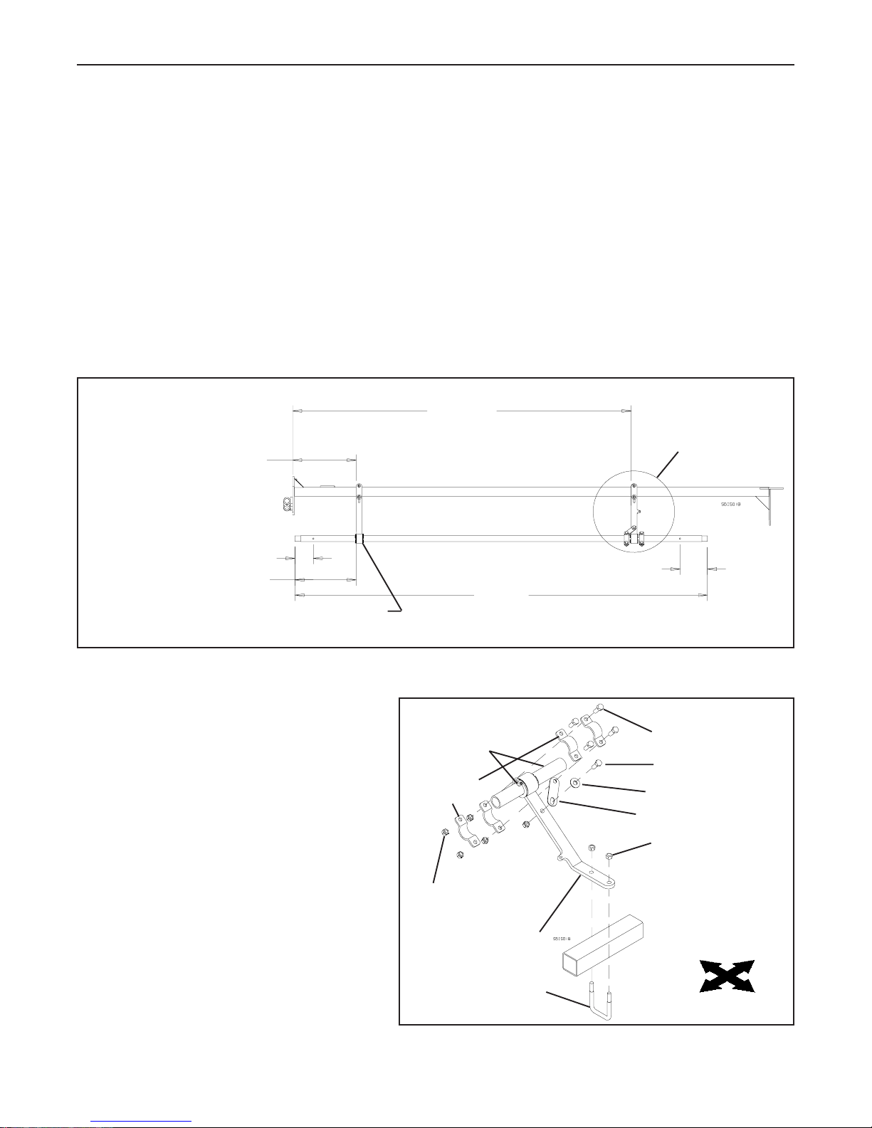
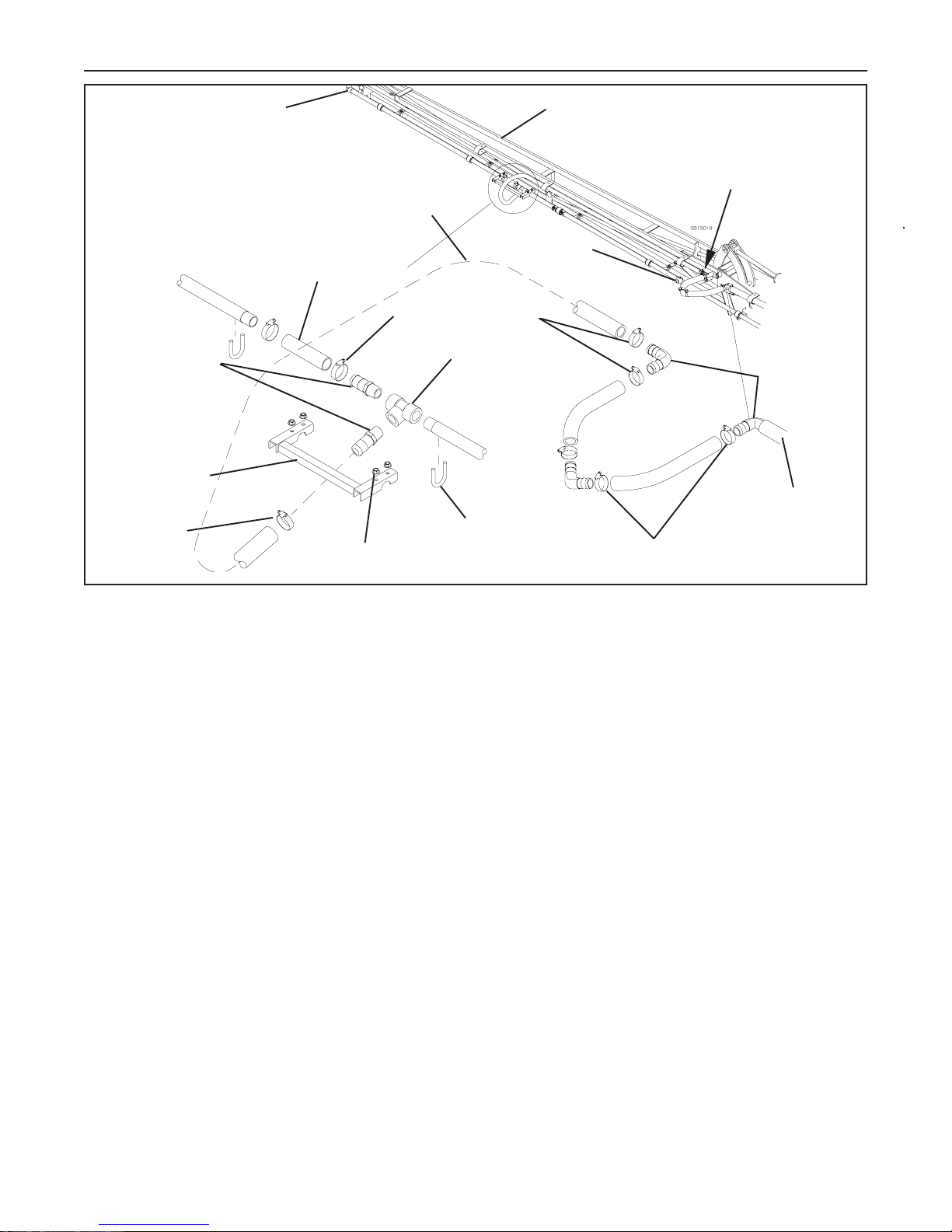
2.4 80’ Outer Boom Assembly
1. Mount one of the regular Short Boom Struts and one of the Short Struts with the tab on the side to the lower
tube on the Inner Boom using a 3/8”x 2” Sq. U-bolt, flatwasher and two lock nuts for each.. Position the struts
as shown in Fig. 2.10. Two extra Boom Struts are required if Poly Spray Pipes are being used. The extra
struts are shown as dashed lines in Fig. 2.10.
2. Slide the 90” spray pipe into the struts. Position it as shown in Fig. 2.10. Take note of the holes in the spray
pipe and position them as shown.
3. Assemble the Spray Pipe Clamps onto the spray pipe using four 5/16”x 1” bolts and lock nuts as shown in Fig.
2.10. The Pipe Clamp Strap mounts to the boom strut with a 3/8”x 1” bolt, flatwasher and lock nut. The other
end is attached between one set of the Spray Pipe Clamps. See Fig. 2.11. Tighten the screws in the plastic
spray pipe bushings so they are clamped to the spray pipes. Do not overtighten the screws.
Top View of the 80’ Left Outer Boom
73 7/8”
13 7/8”
See Fig. 2.11
for details
4”
13 3/8”
If the Quick Spray Angle Kit will be installed,
mount the spray pipe clamps here.
Fig. 2.10 80’ Outer Boom Assembly
Note: If the Quick Spray Angle Kit will be installed
on the sprayer, move the Spray Pipe Clamps
to the strut shown. Do not mount the Pipe
Clamp Strap.
4. Thread the 1” FPT Elbow onto the spray pipe
as shown in Fig. 2.12. Make sure the holes in
the spray pipe are pointing straight down and
the elbow is pointing straight back. Use pipe
sealant on the fitting.
5. Screw a 1” MPT x 1 1/4” HB Fitting into the
elbow. Use pipe sealant on the threads.
90”
Wrap friction tape
around pipe, under
both clamps
Spray Pipe
Clamp
5/16” Lock Nut
Outer Strut Assembly
6”
5/16”x 1” Bolt
3/8”x 1” Bolt
3/8” Flatwasher
Pipe Clamp Strap
3/8” Lock Nut
Rear
Left
3/8”x 2” U-bolt x 3”
Right
Fig. 2.11 Typical Boom Strut Assembly
21
Front
SECTION 2 - Boom Assembly
6. Connect one end of a 1 1/4” ID x 18” Hose to the 1 1/4” HB Elbow mounted to the inner boom using a
1 1/2” hose clamp. This elbow has the hose which connects to the electric ball valve clamped to it. See Fig.
2.12.
7. Insert the 1 1/4” HB Elbow from the parts box into the other end of the 18” hose. Secure it in place with a
1 1/2” Hose clamp.
8. Install another 1 1/4” ID x 18” Hose and a 1 1/4” HB Elbow into the elbow just assembled. Secure in place
with two 1 1/2” Hose clamps.
9. Connect one end of the 1 1/4” ID x 60” hose to the other end of the elbow using a 1 1/2” hose clamp.
10. Slide the other end of the 60” hose through the hose holder welded to the boom, and connect it to the hose
barb fitting on the spray pipe using a 1 1/2” hose clamp.
11. Secure the 1 1/4” HB Elbow to the support welded to the boom using a 2” hose clamp. See Fig. 2.12.
12. If the Quick Spray Angle kit has been installed, rotate the spray pipes 95o to make sure the hoses do not bind.
Make any necessary adjustments.
13. Repeat steps 1 through 12 on the Right Outer Boom.
See Fig. 2.17 for this
plumbing joint.
1 1/4” ID x 60” Hose
Outer Boom Spray Pipe
1” FPT Elbow
1” MPT x
1 1/4” HB Insert
1 1/2” Hose
Clamp
1 1/2” Hose Clamp
80’ Outer Boom
2” Hose Clamp
1 1/4” ID x
18” Hose
60” Hose goes through
this hose holder
1 1/4” HB
Elbow
Clamp Hose Barb
Elbow to this support
using a 2” hose clamp
Fig. 2.12 80’ Outer Boom and Tip Plumbing Assembly
1 1/4” HB Elbow
1 1/2” Hose Clamp
22
SECTION 2 - Boom Assembly
2.5 90’ Outer Boom Assembly
1. Mount three of the regular Short Boom Struts and one of the Short Struts with the tab on the side to the lower
tube on the Inner Boom using a 3/8”x 2” Sq. U-bolt, flatwasher and two lock nuts for each.. Position the struts
as shown in Fig. 2.13. Two extra Boom Struts are required if Poly Spray Pipes are being used. The extra
struts are shown as dashed lines in Fig. 2.13.
Top View of the 90’ Outer Boom
133 7/8”
93 7/8”
53 7/8”
13 7/8”
See Fig. 2.11
for details
13 3/8”
4”
70”
6”
20”
6”
70”
4”
13 3/8”
If the Quick Spray Angle Kit will be installed,
mount the spray pipe clamps here.
Fig. 2.13 90’ Outer Boom Assembly
2. Slide two 70” spray pipes into the struts. Position them as shown in Fig. 2.13. Take note of the holes in the
spray pipes and position them as shown.
3. Loosely assemble the Spray Pipe Clamps onto the spray pipe using four 5/16”x 1” bolts and lock nuts as
shown in Fig. 2.11 and Fig. 2.13. The Pipe Clamp Strap mounts to the boom strut with a 3/8”x 1” bolt,
flatwasher and lock nut. The other end is attached between one set of the Spray Pipe Clamps. See Fig. 2.11.
Note: If the Quick Spray Angle Kit will be installed on the sprayer, move the Spray Pipe Clamps to the strut
shown. Do not mount the Pipe Clamp Strap.
4. Thread the 1” FPT Tee onto the right spray pipe as shown in Fig. 2.14. Make sure the holes in the spray pipe
are pointing straight down and the tee is pointing back, 120o from vertical. Use pipe sealant on the fitting.
5. Screw the 1” MPT x 1 1/4” HB Fittings into the tee. Use pipe sealant on the threads.
6. Slide the 1 1/4” ID x 6” hose onto the hose barb that is inline with the spray pipes. Slip the other end onto the
left spray pipe. Make sure the holes in the pipe are pointing straight down. Secure the hose to the spray pipes
using two 1 1/2” Hose Clamps. Do not tighten the clamps yet.
7. Measure the distance between the inner holes in both spray pipes and adjust this distance to 20”. Make sure
the nozzle holes in both spray pipes are inline with each other. Tighten the hose clamps.
23
SECTION 2 - Boom Assembly
See Fig. 2.17 for this
plumbing joint.
1” MPT x
1 1/4” HB Insert
Pipe Joiner
1 1/2” Hose
Clamp
1 1/4” ID
Hose x 6”
1 1/4” ID x 120”
Hose
1” FPT Cap
1 1/2” Hose Clamp
1” FPT Tee
5/16” x 1 3/8” U-bolt
5/16” Flange Lock Nut
90’ Outer Boom
Clamp Hose Barb
Elbow to this support
using a 2” Hose Clamp
1 1/4” HB
Elbow
To the Left
Electric Ball Valve
1 1/2” Hose Clamp
Fig. 2.14 90’ Outer Boom Plumbing Assembly
8. Attach the Pipe Joiner to both spray pipes using two 5/16” x 1 3/8” U-bolts and flange lock nuts. Tighten the
bolts on the spray pipe clamps which position the spray pipes. Tighten the screws in the plastic spray pipe
bushings so they are clamped to the spray pipes. Do not overtighten the screws.
9. Thread a 1” FPT Cap onto the open end of the spray pipe as shown in Fig. 2.14.
10. Connect one end of a 1 1/4” ID x 18” Hose to the 1 1/4” HB Elbow mounted to the inner boom using a
1 1/2” hose clamp. This elbow has the hose which connects to the electric ball valve clamped to it. See Fig.
2.14. Insert a 1 1/4” HB Elbow from the parts box into the other end of the 18” hose. Secure it in place with
a 1 1/2” hose clamp.
11. In stall another 1 1/4” ID x 18” Hose and a 1 1/4” HB Elbow into the elbow just assembled. Secure it in place
with two 1 1/2” hose clamps.
12. Connect one end of the 1 1/4” ID x 120” hose to the other end of the elbow using a 1 1/2” hose clamp.
Slide the other end of the 120” hose through the hose holder welded to the boom, and connect it to the hose
barb fitting on the spray pipe Tee using a 1 1/2” hose clamp. The hose must go under the Pipe Joiner.
13. Secure the 1 1/4” HB Elbow to the support welded to the boom using a 2” hose clamp. See Fig. 2.14.
14. If the Quick Spray Angle kit has been installed, rotate the spray pipes 95o to make sure the hoses do not bind.
Make any necessary adjustments.
15. Repeat steps 1 through 14 on the Right Outer Boom.
24
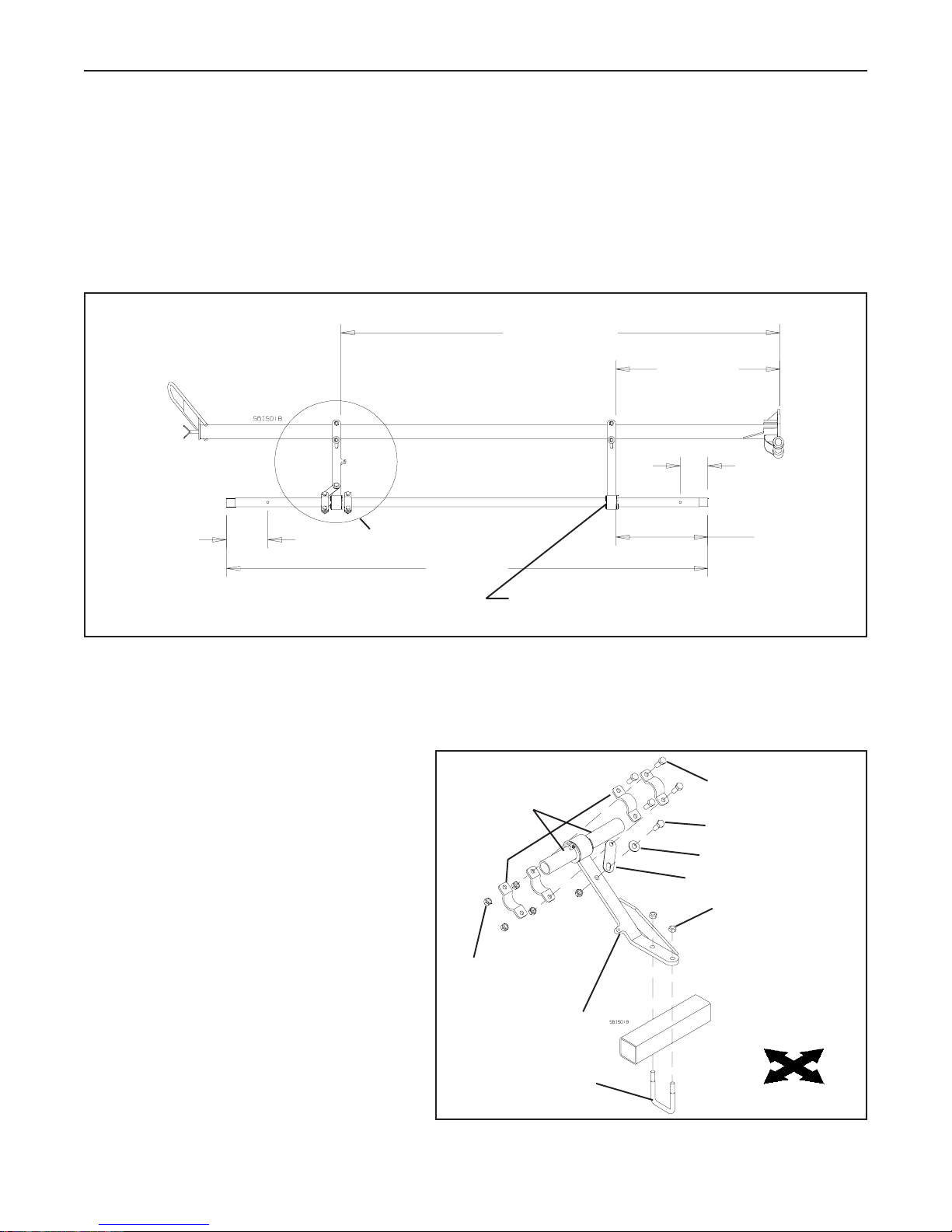
SECTION 2 - Boom Assembly
2.6 80’ & 90’ Outer Boom Tip Assembly
1. Mount one of the Short Boom Struts with the gusset and one of the Short Struts with the tab and the gusset on
the side to the lower tube on the Inner Boom using a 3/8”x 2” Sq. U-bolt, flatwasher and two lock nuts for
each. Position the struts as shown in Fig. 2.15. One extra Boom Strut is required if Poly Spray Pipes are being
used. The extra strut is shown as dashed lines in Fig. 2.15.
2. Slide a 70” spray pipe into the struts. Position it as shown in Fig. 2.15. Take note of the holes in the spray pipe
and position them as shown.
Top View of the Outer Boom Tip
63 7/8”
23 7/8”
4”
6”
See Fig. 2.16 for details
13 3/8”
70”
If the Quick Spray Angle Kit will be installed,
mount the spray pipe clamps here.
Fig. 2.15 Outer Boom Tip Assembly
3. Assemble the Spray Pipe Clamps onto the spray pipe using four 5/16”x 1” bolts and lock nuts as shown in Fig.
2.15 and 2.16. The Pipe Clamp Strap mounts to the boom strut with a 3/8”x 1” bolt, flatwasher and lock nut.
The other end is attached between one set of
the Spray Pipe Clamps. See Fig. 2.16.
Tighten the screws in the plastic spray pipe
bushings so they are clamped to the spray
pipes. Do not overtighten the screws.
Wrap friction tape
around pipe, under
both clamps
5/16”x 1” Bolt
3/8”x 1” Bolt
Spray Pipe
Note: If the Quick Spray Angle Kit will be installed
Clamp
3/8” Flatwasher
Pipe Clamp Strap
on the sprayer, move the Spray Pipe Clamps
to the strut shown. Do not mount the Pipe
3/8” Lock Nut
Clamp Strap.
5/16” Lock Nut
Tip Boom Strut
with Gusset & Tab
3/8”x 2” U-bolt x 3”
Rear
Right
Fig. 2.16 Typical Boom Tip Strut Assembly
25
Left
Front
 Loading...