


2200
Builder Series
Programmable Thermostats
Single Stage Heat / Cool
2000
2000NC
2200
Multi-Stage 2 Heat / 1 Cool
2200NC
Before Installing, Programming or Operating,
PLEASE READ ALL INSTRUCTIONS
Specifications
1
2
Installation
3
Testing Your New Thermostat
4
Programming User Settings
5
Setting Your Energy
Saving Program
Conventional and Heat Pump
Conventional and Heat Pump
6
Temperature Adjustment
7
Additional Operation
Features
8
Battery Replacement
9
Troubleshooting
10
Wiring Diagrams
WARNING
Important Safety Information
• Always turn off power to the air conditioning or heating system prior to
installing, removing, cleaning or servicing thermostat.
• This thermostat requires either 24 Volts AC Power or two (2) properly installed
“AA” alkaline batteries for normal operation and control of the heating or
cooling system. Refer to “Low Battery Detection and Replacement” section for
more information.
• This thermostat also requires two (2) properly installed “AA” alkaline batteries
to retain clock setting in the event of loss of AC Power due to a power outage
or rolling blackouts when used as a hardwired thermostat.
• This thermostat should only be used as described in this manual. Any other
use is not recommended and will void the warranty.
Specifications
1
• Electrical Rating: 24 Volt AC (18-30 Volt AC)
1 amp maximum load per terminal
2 amp total maximum load (all terminals) (Model 2000, 2000NC)
3 amp total maximum load (all terminals) (Model 2200, 2200NC)
• Control Range: 45˚ - 90˚ F (7˚ - 32˚ C)
• Accuracy: +/- 1˚ F (+/- .5˚ C)
• AC Power: 18-30 Volt AC
• DC Power: 3.0 Volt DC (2 AA Alkaline batteries included)
Specifications
1
• Model 2000, 2000NC: Compatibility with low voltage single stage gas, oil or
electric heating or cooling systems, including single stage heat pumps; can
also be used on 250mv to 750mv millivolt heating only systems.
• Model 2200, 2200NC: Compatibility with low voltage multi-stage gas, oil or
electric heating or cooling systems, including multi-stage heat pumps.
• Model 2000, 2000NC Terminations: Rc, Rh, B, O, Y, W, G, C
• Model 2200, 2200NC Terminations: R, O, B, C, Y1, E/W1, G, W2
2
Installation
Replacing Existing Thermostat
Most thermostats have three parts:
• The cover, which may snap or hinge over the existing thermostat.
• The electronics or body, which controls the existing system.
• The sub-base, where the wires attach through the wall to the existing system.
1. Always turn off power to the air conditioning or heating system prior to
removing existing thermostat.
2.
Carefully remove the cover and electronics body from the old thermostat sub-base.
Depending on the brand, these parts may pull off or need to be unscrewed. The
old sub-base should remain wired and on the wall until steps 4 and 5.
3. Label every old wire with the letter of the connection to which the wire is
attached. Example letters are R, M, Y etc. Depending on the brand of the old
thermostat, your letters may be different.
4. After labeling the old wires, loosen each connection and remove them from old
sub-base. Secure the wires to prevent them from slipping into the hole in the wall.
5. Remove the old sub-base from the wall, again being careful that the wires do
not slip into the hole in the wall.
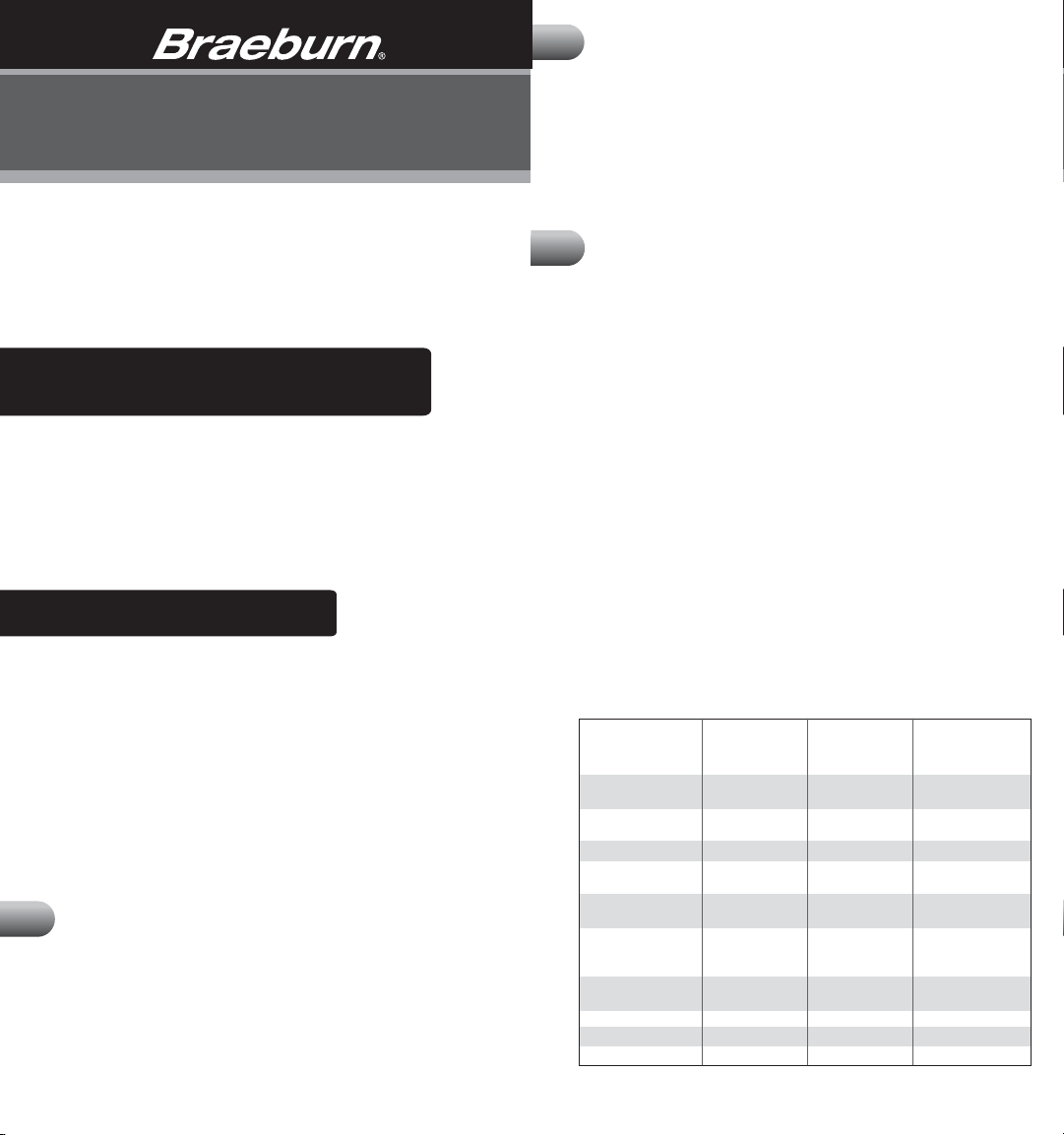
6. Use the chart below to determine the new thermostat connections. As an
example, if the old thermostat had a G connection, it goes to G on the new
thermostat. Note the chart includes information for Braeburn
2200 and 2200NC thermostats. Be sure to use the correct column for the
new thermostat.
Old Terminal from
Existing Thermostat
V or Rc Rc Cooling
Transformer
M, 4, Rh, or R Rh Heating
Transformer
R, V-VR or VR-R R 24 VAC
B B B Reversing Valve
(Heating)
O O O Reversing Valve
(Cooling)
Y, Y1 or M Y Y1 Cooling or
Compressor for
HP System
E, H, W, W1 or 4 W E/W1 1st Stage Heat
or Emergency Heat
G or F G G Fan Control
C, X or B C C 24 VAC Common
W1, W2 or W-U W2 2nd Stage Heat
co nt.
New Terminal for
New Thermostat
(2000, 2000NC)
New Terminal for
New Thermostat
(2200, 2200NC)
®
2000, 2000NC,
Terminal
Description
1

2
Installation
co nt.
2
Installation
co nt.
NOTE–MODEL 2000, 2000NC: This thermostat is designed for use with 24
Volt-AC low voltage single stage gas, oil or electric heating or cooling systems,
including single stage heat pumps and can also be used on 250mv to 750mv
millivolt heating only systems. Do not use this thermostat on applications with
voltages above 30 Volts AC.
NOTE–MODEL 2200, 2200NC: This thermostat is designed for use with 24
Volt-AC low voltage multi-stage gas, oil or electric heating or cooling systems,
including multi-stage heat pump systems. Do not use this thermostat on
applications with voltages above 30 Volts AC.
Installing New Thermostat
NOTE: If installing this thermostat in a new installation, locate the thermostat
4 to 5 feet above the floor in accordance with applicable building codes. Install the
thermostat in a location that provides good airflow characteristics and avoid areas
behind doors, near corners, air vents, direct sunlight or heat generating devices.
Installation in these areas could impact thermostat performance. Wiring must
conform to all building codes and ordinances as required by local and national
code authorities having jurisdiction.
1. Always turn off power to the air conditioning or heating system prior to
installing thermostat.
2. Place system switch on front of thermostat to the OFF position.
3. Place fan control switch on front of thermostat to the AUTO position.
4. Remove front of thermostat body from sub-base by pressing release latch on
bottom of thermostat.
5. Place the thermostat sub-base against wall in the desired thermostat location.
6. Guide thermostat wires through hole in sub-base and continue to hold
against wall.
Mark placement of mounting holes as appropriate and drill using a 3/16" drill bit.
7.
8. Gently tap supplied plastic anchors into the holes in the wall.
9. Place the thermostat sub-base against the wall in the desired location, making
sure the mounting holes are aligned and the thermostat wires are inserted
through the opening in sub-base.
10. Fasten sub-base to wall using supplied screws.
11.
Connect wires to quick wiring terminal block using the new terminal designations.
Refer to Wiring Diagram in section 10 of this manual for assistance.
12. Make sure all of the wire connections are secure and are not touching
any other terminal to prevent electrical shorts and potential damage to
the thermostat.
13. Turn the front thermostat body over, exposing the rear view of the circuit board.
14. Locate the internal ˚F / ˚C switch on the circuit board. Using your fingers, flip
the switch toward the preferred temperature ˚F / ˚C scale.
15. Locate the internal fan option switch, HG (Gas) / HE (Elec) on the circuit board.
This switch controls the heating system fan delay. Select gas for gas or oil fired
systems. This will allow the furnace to run for a few seconds before initiating
the fan. Select electric for electric heat systems that require the fan to come on
immediately. Using your fingers, flip the switch toward HG (Gas) or HE (Elec).
16. Locate the internal NORM / HP switch on the circuit board. This switch
configures the thermostat for conventional (NORM) heating and cooling systems
or heat pump (HP) systems. Using your fingers, gently flip the switch toward
NORM or HP.
17. Attach front body of thermostat to sub-base of thermostat, being careful to
align the terminal pins on the front body with the terminal block on the sub-base.
2 3
18. Open front thermostat door and open battery compartment door.
19. Install two new "AA" alkaline batteries. Locate the positive (+) ends of the
batteries and match them with the positive (+) terminals located in the battery
compartment. Close battery compartment.
20. Restore system power so you can test installation.
NOTE: If batteries were installed prior to accomplishing steps 14 through 16,
you will need to reset the thermostat to register thermostat switch configurations
prior to programming any user settings. Gently press the RESET button on the
front of the thermostat using a paperclip or a small pencil tip.
NOTE – MODEL 2200, 2200NC:
system and the system switch is in the EMER position, the unit will still function
in a conventional 2 stage HEAT mode, but the display will flash NO AUX SET.
3
Testing Your New Thermostat
WARNI N G !
• Do not short (or jumper) across terminals on the gas valve or at the heating or
cooling system control board to test the thermostat installation. This could
damage the thermostat and void the warranty.
• Do not select COOL mode if the outside temperature is below 50˚ F (10˚ C).
This could damage the controlled cooling system and cause personal injury.
• This thermostat includes an automatic compressor protection feature to avoid
potential damage to the cooling system from short cycling. This thermostat
automatically provides a 5-minute delay after turning off the cooling or heating
system output to protect the compressor.
NOTE: Test your thermostat prior to programming any user settings. Pressing the
RESET button will erase any user entries previously programmed and return them
to their default values.
1. Place the system switch in the HEAT position.
2. Press and hold the button on the keypad until the set point temperature setting
is a minimum of 3 degrees higher than the current room temperature. The
heating system should start within several seconds. The fan may not turn on
immediately due to the heating system built-in fan delay.
3. Place the system switch in the OFF position. The heating system should stop
within several seconds with conventional heating or cooling systems. On heat
pump systems you must wait 5 minutes for the automatic compressor short
cycle protection period to expire, or press the RESET button to bypass this
feature for initial testing purposes. Pressing the RESET button will erase any
user program settings.
4. Place the system switch in the COOL position.
5. Press the button on the keypad until the set point temperature is a minimum
of 3 degrees lower than the current room temperature.
6. The cooling system should start within several seconds. Place the system switch
in the OFF position. The cooling system should stop within a few seconds.
7. Place the fan switch in the ON position. The system blower should start.
8. Place the fan switch in the AUTO position. The system blower should stop.
NOTE: When you place the system switch in the COOL or HEAT modes of
operation, the appropriate indicator will also appear in the LCD display when the
system is running. When you place the system switch in the OFF mode, the
display will indicate OFF.
If the thermostat is configured for a conventional
Read BEFORE Testing
4
Programming User Settings
4
Programming User Settings
co nt.
Default Thermostat Settings
Function Status After Reset
Operation Mode Normal Operating Mode
Temperature Hold Permanent and Temporary Hold Cleared
Clock 12:00 p.m., Monday
Room Temperature 70˚ F (21.0˚ C), to be renewed within
5 seconds
Set Point Temperature According to System Switch
62˚ F (17.0˚ C) for Heat and Off
83˚ F (28.0˚ C) for Cool
Temperature Scale ˚F or ˚C dependent on switch setting
Operating Program DAY program, Monday
Low Battery Warning Off, to be renewed within 5 seconds
1st Stage Differential 0.5˚ F (0.25˚ C)
2nd Stage Differential 2˚ F (1.0˚ C)
Short Cycle Protection Timer Reset
Output Relays Off
Filter Check Monitor 0 days-off
Extended Hold Indefinite
Adaptive Recovery Mode Off
Setting Current Time of Day and Day of Week
NOTE: It is important for you to set the current time of day (note AM/PM indicator
in display), and the current day of week correctly to avoid problems with
program execution.
1. When in normal operating mode, press the
DAY/TIME keypad button. The LCD display
will be cleared except for the time, am/pm
indicator and the day of the week. The
hour portion of the time will flash. Press
the or button to set the current hour.
2. Press the DAY/TIME button again. The minute portion of the time will flash.
Press the or button to set the current minute.
3. Press the DAY/TIME button again. The day of the week indicator will flash.
Press the or button to set the current day of the week.
4. Press the DAY/TIME button again and the thermostat will return to normal
operating mode.
NOTE: The thermostat will return to normal operating mode automatically after
30 seconds if no key is pressed. It will also return to normal operating mode
immediately if the RETURN button is pressed.
Setting Thermostat User Options
The default user options are compatible with most systems and applications.
They are normally set at the time of installation and usually do not require
modification under normal operating conditions. If you wish to change these
settings, simply follow the instructions below.
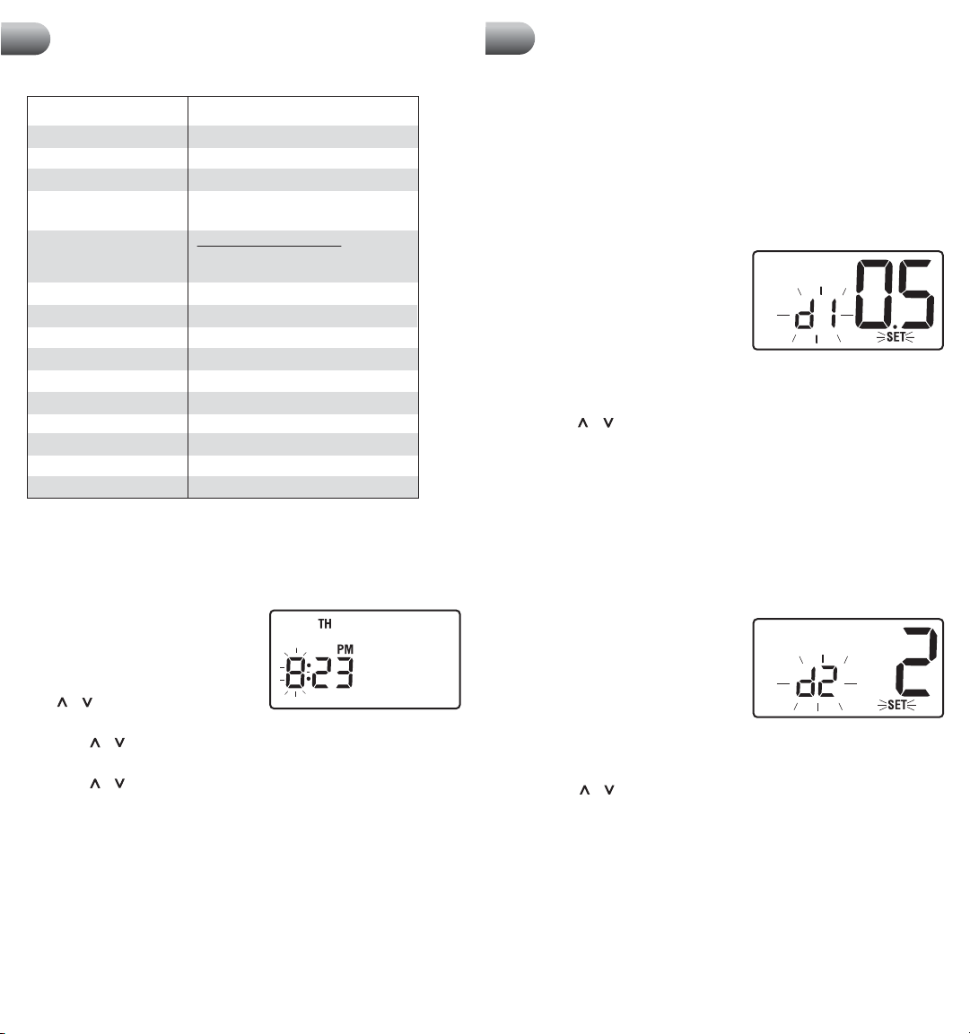
Setting First Stage Differential
NOTE: The temperature differential settings are the same for both the heating
and cooling systems.
The default setting is 0.5˚ F (0.25˚ C).
The room temperature must change .5˚ F
(0.25˚ C) from the set point temperature
before the thermostat will initiate the
system in heating or cooling.
1. In normal operating mode, press and hold the RETURN button for 4 seconds.
The LCD display will show "SET D1 x˚", where "x" equals the ˚F / ˚C
differential setting. This is the current first stage differential setting.
2. Press the or buttons to set the first stage differential to your desired
setting of .5˚, 1˚, or 2˚ F (.2˚, .5˚ or 1˚ C).
NOTE – MODEL 2000, 2000NC: Once you have finished setting the first stage
differential, you can wait 15 seconds and the thermostat will return to the
normal operating mode. Or you can press the RETURN button to return to normal
operating mode.
NOTE – MODEL 2200, 2200NC:
differential,
normal operating mode.
Setting Second Stage Differential (Model 2200, 2200NC)
The default setting is 2˚ F (1.0˚ C). The room
temperature must change 2˚ F (1.0˚ C) in
addition to the first stage differential setting
before the thermostat will initiate the
second stage of the system in heating.
1. Press and hold the RETURN button again and the LCD display will show “SET
D2 x˚”, where “x” equals the ˚F / ˚C differential setting. This is the current
second stage differential setting.
2. Press the or buttons to set the second stage differential to your desired
setting of 2˚, 3˚, 4˚, 5˚ or 6˚ F (1˚, 1.5˚, 2˚, 2.5˚ or 3˚ C).
NOTE – MODEL 2200, 2200NC: Once you have finished setting the second
stage differential, wait 30 seconds and the thermostat will return to the normal
operating mode.
NOTE: To erase all user program settings, gently press RESET button using a
paper clip or a small pencil tip. This will return all thermostat settings to their
default values, erasing all program settings entered by the user.
wait 30 seconds and the thermostat will automatically return to the
If you do not wish to change the second stage
4
5
 Loading...