

Brady IP Printer series, BP-IP300, BP-IP600, BP-IP300-C, BP-IP600-C Service Manual
...
Service Manual
Edition 12/07

2 Service Manual Edition 12/07
Brady IP Series Printer
Service manual for the following products
Copyright by Brady Worldwide, Inc.
All specifications about delivery, design, performance and weight are given to
the best of our current knowledge and are subject to change without prior
notice.
All rights reserved, including those of the translations.
No part of this manual nor any translation may be reproduced or transmitted
in any form or by any means, for any purpose other than the purchaser’s
personal use, without the express written permission of Brady.
PRODUCT
NUMBER
CATALOG
NUMBER
PRODUCT DESCRIPTION
103957 BP-IP300 BRADY IP PRINTER - 300DPI STANDARD
103958 BP-IP600 BRADY IP PRINTER - 600DPI STANDARD
103959 BP-IP300-C BRADY IP PRINTER - 300DPI W/CUTTER
103960 BP-IP600-C BRADY IP PRINTER - 600DPI W/CUTTER
103961 BP-IP300-P BRADY IP PRINTER - 300DPI PEEL/PRESENT
103962 BP-IP600-P BRADY IP PRINTER - 600DPI PEEL/PRESENT
103963 BPA-IP-C-FI BRADY IP PRINTER CUTTER FIELD INSTALL
103964 BPA-IP-P-FI BRADY IP PRINTER PEEL/PRESENT FIELD INSTALL

Edition 12/07 Service Manual 3
Brady IP Series Printer
Table of Contents
Table of Contents
1 Important Information .......................................................................................................4
1.1 General safety instructions..................................................................................................4
1.2 Protective devices ...............................................................................................................4
1.3 Handling electricity...............................................................................................................5
1.4 Procedure in case of accidents............................................................................................5
2 Replacing assembly units................................................................................................6
2.1 Device overview...................................................................................................................6
2.2 Tools....................................................................................................................................7
2.3 Replacing the control panel.................................................................................................8
2.4 Replacing the cover.............................................................................................................9
2.5 Replacing the outer casing................................................................................................10
2.6 Replacing the print mechanism .........................................................................................12
2.7 Replacing the printhead.....................................................................................................13
2.8 Replacing the print roller....................................................................................................14
2.9 Replacing the brake of the ribbon supply hub ...................................................................15
2.10 Replacing the drive of the cutting unit................................................................................16
2.11 Replacing the blades of the cutting unit.............................................................................17
2.12 Replacing the CPU PCB....................................................................................................18
2.13 Replacing the BDC PCB....................................................................................................19
2.14 Replacing the power unit...................................................................................................20
3 Settings and Adjustments ..............................................................................................21
3.1 Measuring the rewind torques ...........................................................................................21
3.2 Adjusting the rewind torques .............................................................................................23
3.3 Adjusting the print mechanism...........................................................................................24
3.4 Adjusting label sensor........................................................................................................27
4 Block diagram..................................................................................................................28
5 Index .................................................................................................................................30

4 Service Manual Edition 12/07
Important Information
Brady IP Series Printer
1 Important Information
1.1 General safety instructions
This service manual is intended for use by qualified service and maintenance personnel. For more operation and configuration information, refer to the user or configuration manual.
Follow the general safety rules below:
• Keep the area around the device clean at all times!
• Work with safety in mind.
• Parts of device that are removed during the maintenance work must be put in a safe place.
• Avoid risks of tripping over.
1.2 Protective devices
Wear protective goggles for:
• Knocking pins or similar parts in or out with a hammer.
• Using spring hooks.
• Inserting or removing springs, retaining rings or grip rings.
• Using solvents, cleansers or other chemicals.
DANGER!
Danger to life and limb from increased current flow through metal parts in contact with the
device.
⇒ Do not wear clothing with metal parts.
⇒ Do not wear jewelry.
⇒ Do not wear spectacles with metal frames.
CAUTION!
Items of clothing drawn into the device by moving parts can lead to injuries.
⇒ Do not wear any items of clothing which could get caught by moving parts.
WARNING!
There is a risk of injury if protective devices are missing or defective.
⇒ Replace all protective devices (covers, safety notices, grounding cables etc) after mainte-
nance work has been completed.
⇒ Replace parts that have become defective or unusable.

Brady IP Series Printer
Important Information
Edition 12/07 Service Manual 5
1.3 Handling electricity
The following work may only be done by trained and qualified electricians:
• Work on electrical components.
• Work on an open device still connected to the mains supply.
General precautions before starting maintenance work:
• Find out where the emergency and power switches are so that they can be quickly thrown in an
emergency.
• Disconnect the current supply before carrying out the following work:
− Installing or removing power units.
− Working in the immediate vicinity of open power supply components.
− Mechanical check of power supply components.
− Modifying circuits in the device.
• Test the zero potential of the device parts.
• Check the working area for possible sources of danger, such as wet floors, defective extension
cables, defective protective conductor connections.
Additional precautions in the case of exposed voltages:
• Ask a second person to remain near the working site. This person must know where the emergency
and power switches are, and how to switch the current off if danger arises.
• Only use one hand to work on electric circuits of devices tha t are switched on. Keep th e other hand
behind your back or in your pocket.
This prevents electricity from flowing through your own body.
1.4 Procedure in case of accidents
• Act calmly and with great care.
• Avoid danger to yourself.
• Switch off power.
• Request medical assistance.
• Give first aid, if necessary.
6 Service Manual Edition 12/07
Replacing assembly units
Brady IP Series Printer
2 Replacing assembly units
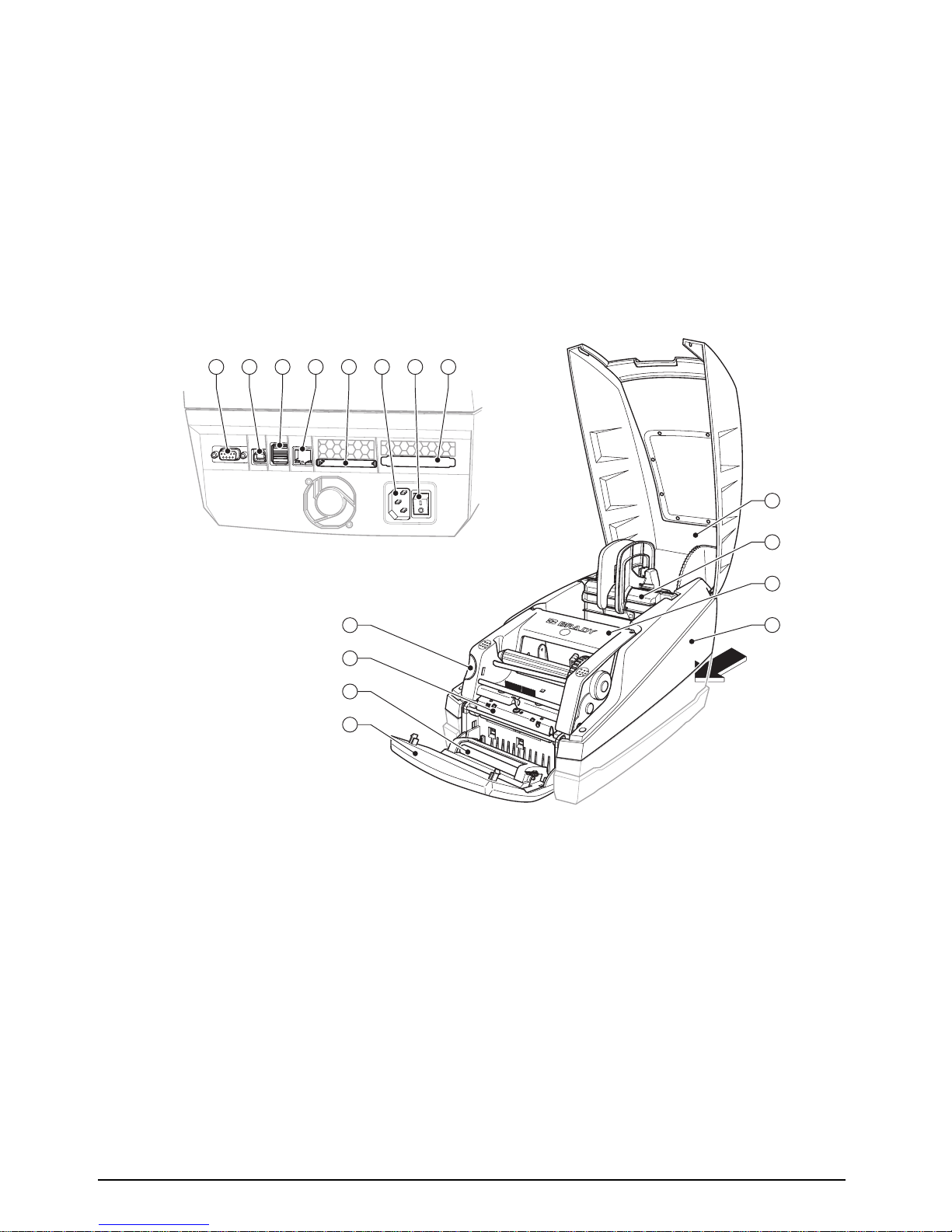
2.1 Device overview
Fig. 1: Overview
1
RS-232 serial interface
2 USB 2.0 High Speed Slave interface
3 Two USB master interfaces for
keyboard and scanner
4 Ethernet 10/100 Base T interface
5 CompactFlash card slot
6 Power supply socket
7 Power switch
8 PC card slot, type II
9 Cover
10 Media holder
11 Printhead assembly
12 Outer casing
13 Unlocking device
14 Printhead holder with printhead
15 Transport locking roller
16 Control panel
A
1 2 3 4 5 6 7 8
16
15
14
13
9
10
11
12
View A

Brady IP Series Printer
Replacing assembly units
Edition 12/07 Service Manual 7
2.2 Tools
• Do not use any worn of damaged tools.
• Only use tools and testing devices that are suitable for the task at hand.
cab special tools:
• Clutch mounting tool (part no. 5541180)
• Service key (part no. 5540301)
Standard tools:
• Screw driver Torx, size TX 10/200
• Hex screwdriver, straight, size 2.5
• Screwdriver with flat blade, size 4
• Flat-nose pliers
• Cylindrical dynamometer (spring scale), 0 - 20 N

8 Service Manual Edition 12/07
Replacing assembly units
Brady IP Series Printer
2.3 Replacing the control panel
Fig. 2: Replacing the control panel
1. Hinge down the control panel (1).
2. Hold the device with one hand, grip the control panel with the other hand, and remove one axle (5)
from of its bearings (3) by pulling strongly.
3. Grip the control panel over the second axle, and pull it until the axle comes out of its bearings.
4. Draw the lugs (2) alongside the bearings (3) out of the device.
5. Pull the plug (4) out of the printer, and put the control panel down in a safe place.
6. Pull the plug (4) of the new control panel into the printer.
7. Slide the lugs (2) past the sides of the bearings (3).
8. Tilt the control panel upwards a little.
9. Hook the axles (5) into their bearings.
10. Press firmly on the control panel until the axles audibly slot into their bearings.
3 4 2 5 31 2
1 Control panel
2 Lug
3 Bearing
4 Plug connector
5 Axle
NOTE!
To convert the printer from the standard or peel/present version to the cutter version by replacing the
control panel the peel-off edge must be removed. To convert the printer in the opposite direction the
peel-off edge must be inserted (see section 2.8, item 5).
NOTE!
Ensure that the plug connector is not damaged.
Brady IP Series Printer
Replacing assembly units
Edition 12/07 Service Manual 9
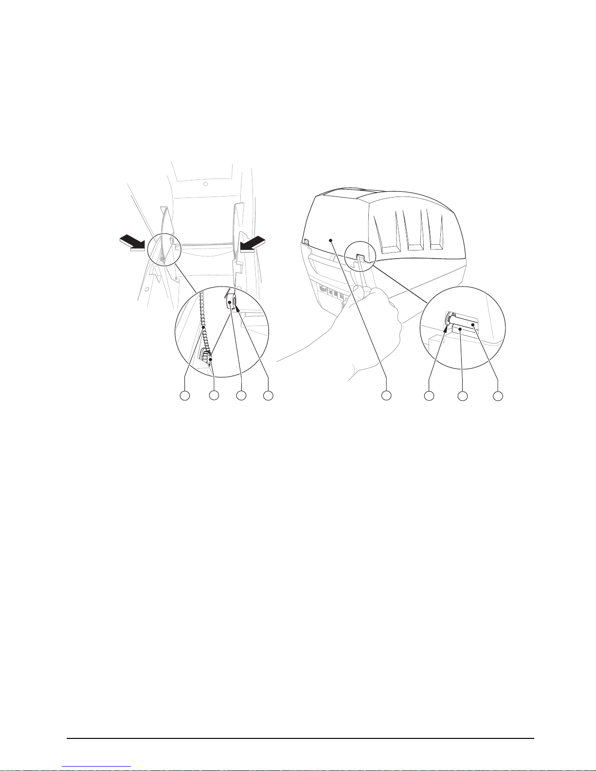
2.4 Replacing the cover
Fig. 3: Replacing the cover
1. Open the cover (5), remove the media hub and label stock.
2. Disconnect the damping mechanism by pressing both toothed lugs (1) towards the center of the
device.
3. Press the cover further back until the axles (4) come out of the guide (7).
4. To fit the new cover, first remove the locking ri ng s (6) an d the axle s (4 ).
5. Place a new cover (5) on the casing, ensure that the damping wheels (2) mesh with the toothed
lugs (1).
6. Push both sides of the axles (4) into the hinged aperture (3) from the inside.
7. Close the cover.
8. Attach the locking rings (6).
1
Toothed lug
2 Damping wheel
3 Hinged aperture cover
4 Axle
5 Cover
6 Locking ring
7 Guide for outer casing
7
5
4
6
3
2
1
4
 Loading...