

Configuration Instructions
Edition 12/09
BP-PR PLUS & BBP72 Series
Auto Cutter Operator’ s Manual
Edition 04/10
Y1147483

Information on the scope of delivery, appearance, performance, dimensions and
Brady Worldwide WH Brady
6555 W. Good Hope Road Lindestraat 21
PO Box 2131 Industriepark C3
Milwaukee, WI 53201 U.S.A. 9240 Zele Belgium
Phone: 1-800-537-8791 Fax: 1-800-292-2289 Tel.: +32 52 457 811
e-mail: support@brady.be
weight reflect our knowledge at the time of printing. We reserve the right to make
modifications.
All rights, including those regarding the translation, are reserved. The replication,
conversion, duplication or divulgement of the whole manual or parts of it for other
intentions than its original intended purpose demand the previous written
authorization by Brady Corporation.
Edition 04/10
ii Edition 04/10 AUTO CUTTER OPERATOR’S MANUAL

Approval
The transfer printers comply with the following safety guidelines:
CE
FCC
EC Low-Voltage Directive (73/23/EEC) EC Machine Directive (98/37/EC) EC
Electromagnetic Compatibility Directive (89/336/EEC)
Conditions from Part 15 of the FCC Regulations for Class A computing devices.
Operation of these devices may cause radio or television interference under
unfavorable conditions, which would need to be remedied by the operator using
countermeasures.
Batteries Directive 2006/66/EC
This product contains a lithium battery. The crossed-out wheeled bin is
used to indicate ‘separate collection’ for all batteries and accumulators
in accordance with European Directive 2006/66/EC. Users of batteries
must not dispose of batteries as unsorted municipal waste. This
Directive determines the framework for the return and recycling of used
batteries and accumulators that are to be collected separately and
recycled at end of life. Please dispose of the battery according to your
local regulations.
Notice to Recyclers
To remove the lithium battery:
1. Disassemble printer and locate the lithium cell battery located on the main
circuit board.
2. To remove, slide the battery from the coin cell retainer, remove the battery
from the board, and dispose of properly.
AUTO CUTTER OPERATOR’S MANUAL iii Edition 04/10

Contents
Introduction
Mounting
Printer Configuration
Loading Material
Operation
1-1-Intended Use ............................................................................................ 1
1-2-Safety Instructions .................................................................................... 2
1-3-Environment ............................................................................................ 3
1-4-Technical Data ........................................................................................ 3
2-1-Mounting the Cutter Tray .......................................................................... 4
2-2-Mounting the Cutter .................................................................................. 4
5-1-Standard Operation .................................................................................. 9
5-2-Operation with External Control ............................................................. 10
Maintenance
6-1-Cleaning ................................................................................................. 11
6-2-Changing the Blades .............................................................................. 13
6-3-Setting Initial State of the Cutter ............................................................. 15
Peripheral Interface
7-1-Pin Assignment ...................................................................................... 17
7-2-Explanation of Signals ........................................................................... 18
7-3-Circuit Diagram of Inputs ........................................................................ 20
7-4-Circuit Diagram of Outputs ..................................................................... 21
Compliance
8-1-UNITED STATES & CANADA .............................................................. 22
8-2-EU Conformity Declaration ..................................................................... 23
iv Edition 04/10 AUTO CUTTER OPERATOR’S MANUAL

1 Introduction
1-1 Intended Use
The device is intended exclusively as an option for the printers of the PR PLUS
printer series (serial number 83761+) and BBP72 printer for cutting suitable
materials that have been approved by the manufacturer. Any other use or use
going beyond this shall be regarded as improper use. The manufacturer/supplier
shall not be liable for damage resulting from unauthorized use; the user shall bear
the risk alone.
Usage for the intended purpose also includes complying with the operating
manual, including the manufacturer‘s maintenance recommendations and
specifications.
The device is manufactured in accordance with the current technological status
and the recognized safety rules. However, danger to the life and limb of the user
or third parties and/or damage to the device and other tangible assets can arise
during use.
The device may only be used for its intended purpose and if it is in perfect working
order, and it must be used with regard to safety and dangers as stated in the
operating manual.
AUTO CUTTER OPERATOR’S MANUAL 1 Edition 04/10
Introduction
CAUTION!
Safety Instructions
1-2 Safety Instructions
• Disconnect the printer from the electrical outlet before mounting or removing
the cutter.
• The cutter may only be operated when it is mounted on the printer.
• Risk of injury, particularly during maintenance, the cutter blades are sharp.
Rotating knife. Do not touch or put fingers near knife.
• Only trained personnel or service technicians should perform maintenance.
• Unauthorized interference with electronic modules or their software can cause
malfunctions. Other unauthorized work or modifications to the device can also
endanger operational safety.
• Always have service work done in a qualified workshop, where the personnel
have the technical knowledge and tools required to do the necessary work.
• Do not remove warning stickers, as then you and other people cannot be aware
of dangers and may be injured.
2 Edition 04/10 AUTO CUTTER OPERATOR’S MANUAL
1-3 Environment
Obsolete devices contain valuable recyclable materials that should be sent for
recycling.
• Send to suitable collection points, separately from residual waste.
The modular construction of the printer enables it to be easily disassembled into
its component parts.
• Send the parts for recycling.
• Take the electronic circuit boards to public waste disposal centers or to the
distributor.
1-4 Technical Data
Standard Cutter
Cutter with peripheral interface *
Introduction
Technical Data
Catalog Number:
PR+-AutoCutter-FI
Catalog Number:
PR+-PerfCutter-FI
For printer type
Material width up to (in/mm) 4.7 / 120
Min. cut length (in/mm)
Material thickness (g/m²)
Power supply
* Interface for trigger switch or external control
Note: The minimum cut length depends on the media, in particular its adhesive
characteristics. Perform preliminary tests. Also test the media, if the media is very
hard, very flexible or very thin.
The cutters have a durability of more than 500,000 cuts. Depending on the type of
the cut material the blades could wear earlier and have to be replaced. Used
blades are not designed regrinding.
An optional Cutter Tray is available:
Cutter Tray 4 Catalog Number: PR+-CutterTray
For printer type PR 300/600 PLUS, BBP72
Material width (in/mm) up to 4.7 / 120
peripheral connector of the printer
PR-300 PLUS
PR-600 PLUS
0.08 / 2
up to 500
Length of the cut pieces (in/mm) up to 3.9 / 100
Stack height (in/mm) up to 1.4 / 36
AUTO CUTTER OPERATOR’S MANUAL 3 Edition 04/10
Mounting
1
2
3
1
2
Mounting the Cutter
2 Mounting
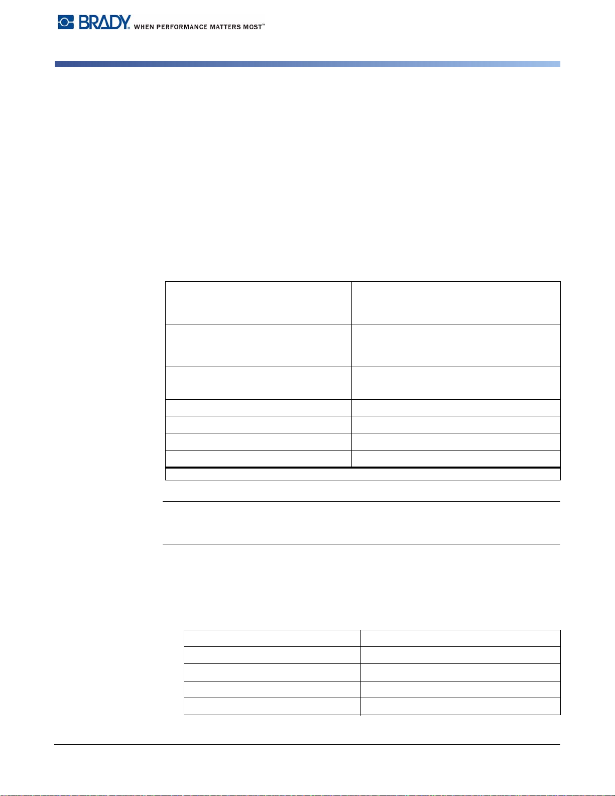
2-1 Mounting the Cutter Tray
1. Loosen the screws [1].
2. Place the cutter tray [2] on the screws [1] in front of the tear-off plate or the
dispense plate and slide it to the left until it stops.
3. Tighten the screws [1].
4. Adjust the length of the cutter tray [2] may by moving the slide [3].
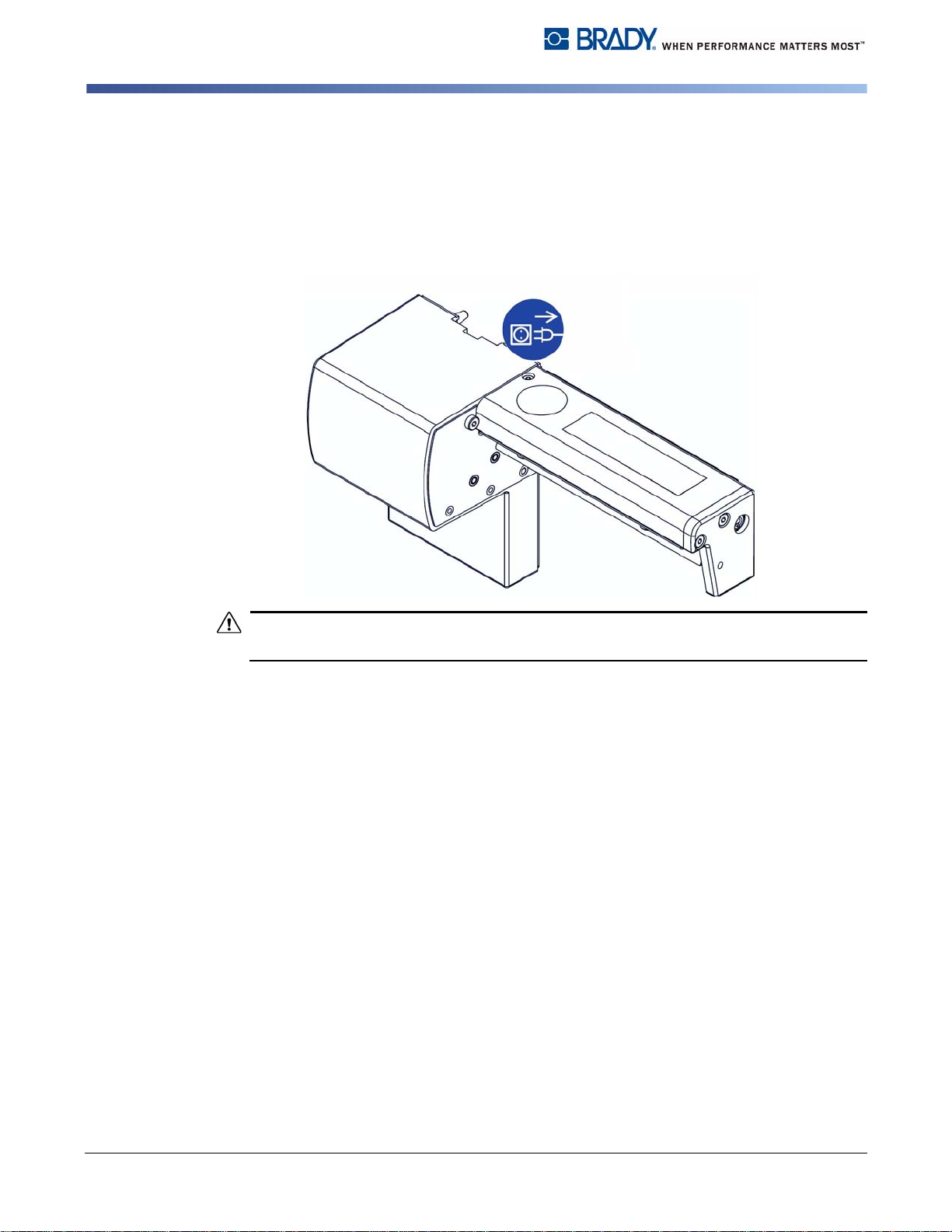
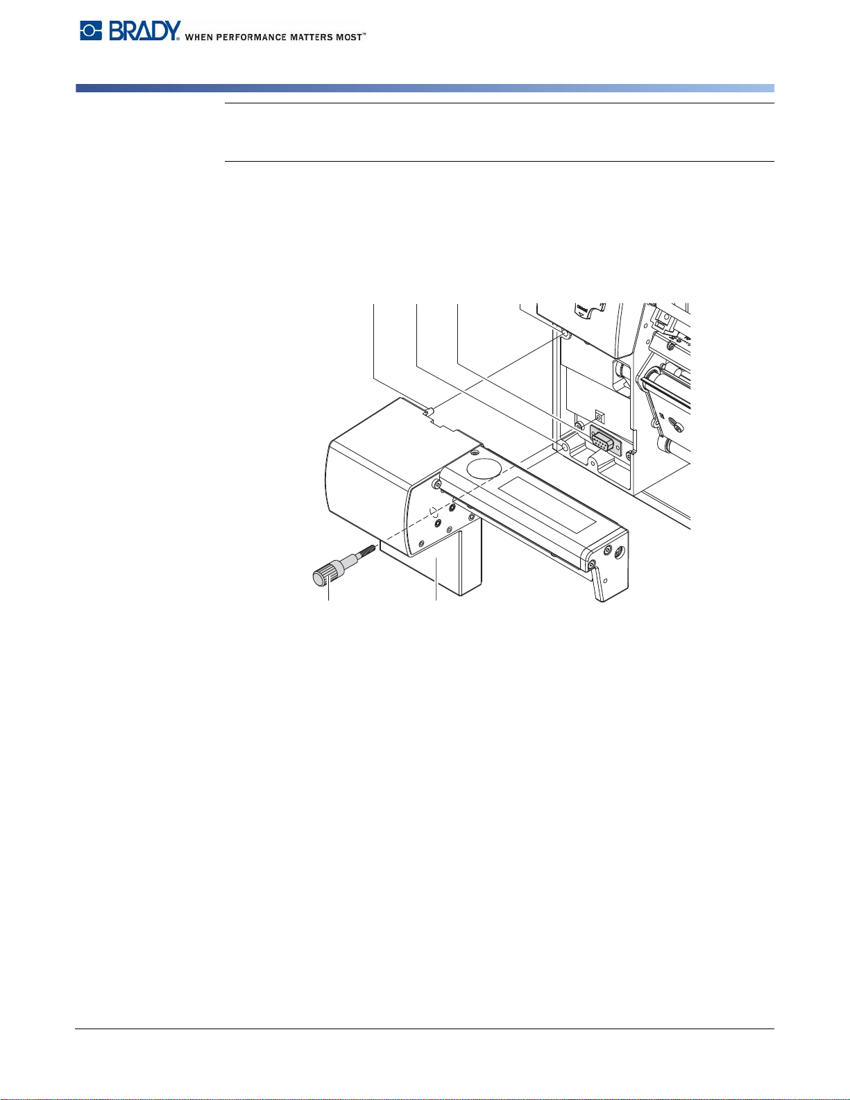
2-2 Mounting the Cutter
Note: Disconnect the printer from the electrical outlet before mounting or removing
the cutter.
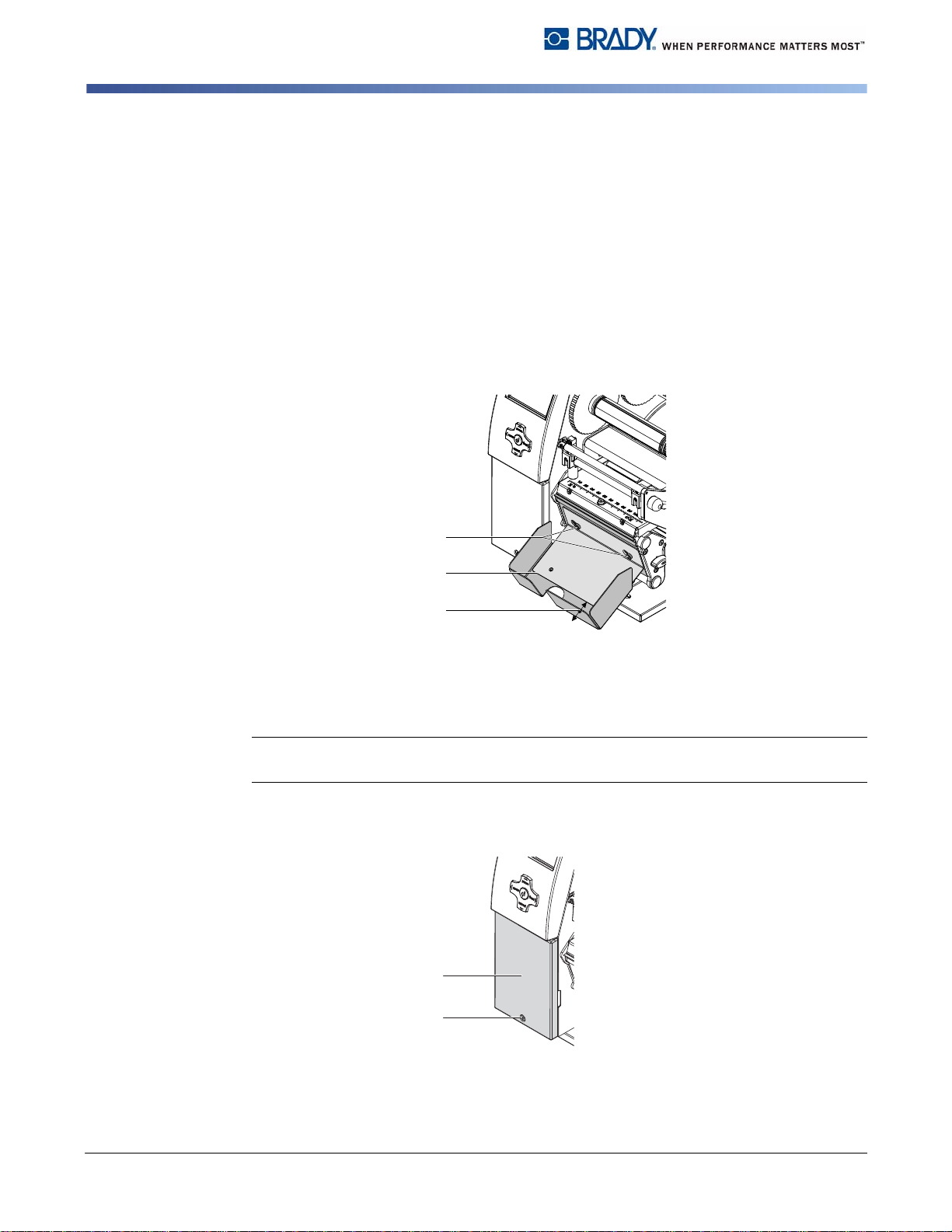
1. Loosen the screw [2].
2. Remove the front cover [1].
4 Edition 04/10 AUTO CUTTER OPERATOR’S MANUAL
Mounting
4543
76
Mounting the Cutter
Note: For cutter operation with PR PLUS printer series and BBP72 printer, a tear-
off plate or a dispense plate must be mounted on the printer to lead the material
through the blades of the cutter.
3. Insert the pins [3] of the cutter [7] into the holes [4] of the printer.
4. Press the cutter against the printer. That way the plug of the cutter will be
connected to the peripheral port [5] of the printer.
5. Secure the cutter [7] with the screw [6].
AUTO CUTTER OPERATOR’S MANUAL 5 Edition 04/10

Printer Configuration
Mounting the Cutter
3 Printer Configuration
Once the cutter is connected to the printer, the printer will automatically recognize
the cutter when it is turned on.
The printer can be configured to suit the individual requirements of cut mode in
the Setup menu. When the cutter is installed, the Cutter menu will appear.
Note: For detailed configuration instructions see the printer User Manual.
Note: Print driver version v4.6.21 or higher is recommended.
The cutter requires additional setup in the driver:
1. Select Advanced Setup tab and set the following options:
•
Sensor Type
•
Cutter:
: Set to material used
batch cut or every
6 Edition 04/10 AUTO CUTTER OPERATOR’S MANUAL

Printer Configuration
Mounting the Cutter
1. For setting the cutter parameters select:
Setup > Machine param. > Cutter .
Parameter Meaning Default
Cutter Configuration of the cutter
> Cut
position
Offset of the cut position relative to the printed
image.
0
Cut position with the initial offset value of “0”
causes to cut in the middle of the gap between two
labels.
If the cut position value is positive, the media will
be advanced before it is cut, that means the
distance between the cut edge and the rear edge
of the label increases.
Notes:
• The values of the setup are basic settings for the actual combination printer/
cutter. After changing the cutter or printer, a re-adjustment may be necessary.
• Changes required for processing different print jobs should be implemented in
additional offsets available in the software.
• The offset values from setup and software are added together for execution.
AUTO CUTTER OPERATOR’S MANUAL 7 Edition 04/10

Printer Configuration
Mounting the Cutter
2. Select the method for recognizing the material and the method of backfeed
when using cut mode under Setup -> Print parameters .
Parameter Meaning Default
Label
sensor
Method for detecting the starting end of the label.
Gap Sensor: Detection using changes in the
Gap
sensor
transparency between the label and label gap.
Bottom-Reflect: Detection using reflex marks on
the bottom of the medium.
Continuos media: Synchronization of the
paper feed when using endless media in cutting
mode.
X After loading media press the feed key to
recognize a short feed and synchronization cut.
Backfeed Method for backfeeding the material.
smart
Backfeeding is necessary in the cutting mode
since the front edge of a second section already
passes the print line when the first label is moved
to the cut position.
always: Backfeeding occurs independently of
print contents.
smart: Backfeeding only occurs when the print
contents of the next section is not yet fully
prepared when cutting the current section.
Otherwise, the second section is pushed on and
completed after removal of the first section
without backfeeding.
8 Edition 04/10 AUTO CUTTER OPERATOR’S MANUAL

4 Loading Material
• Load transfer ribbon and endless material as described in the printer’s
Operator’s Manual.
Use the tear-off mode information for loading endless material for cut mode.
• Place the media strip between the printhead and the drive roller, so that the
front edge of the strip reaches through the cutter.
Note: To prevent jamming, we recommend that material is loaded so that it exits
from the top of the roll.
5Operation
Loading Material
Standard Operation
5-1 Standard Operation
The printer is ready for operation when all connections have been made and all
materials are loaded correctly.
Note: To operate the cutter with continuous material in the printer menu, select
Setup > Print parameters>Label sensor the setting Endless media. Otherwise
no synchronization cut is performed.
1. Switch on the printer. The cutter performs a cut.
2. Press the feed key. For synchronization the media will be moved forward and
cut off.
Printers synchronization is not necessary when the printhead was not opened
between print jobs, even if the printer was powered off between print jobs.
3. Activate the cut mode in the software.
For direct programming use the C-command (see the Programming Manual).
4. Send a print job.
All labels in the job will be printed without stopping and be cut as chosen in the
software: after each label, after a specific quantity of labels, or at the end of a
print job.
AUTO CUTTER OPERATOR’S MANUAL 9 Edition 04/10

Operation
Operation with External Control
5-2 Operation with External Control
The auto cutters with peripheral interface additionally allow the mode “Cut on
Demand”.
In this operating mode it is necessary to connect a trigger switch or an external
control to the peripheral interface on the cutter.
Note: This operating mode requires that there is a connection between Pin 13
(STA) and Pin 12 (GND) at the peripheral interface (see chapter “Peripheral
Interface”).
The printout of one label or a number of labels with the following cut will be
executed if:
• a print job is available.
• the previous cut has finished.
• the trigger switch, or the external control sends the START signal.
10 Edition 04/10 AUTO CUTTER OPERATOR’S MANUAL

6 Maintenance
WARNING
DANGER!
2 21
3 4 4
5
6
6-1 Cleaning
Disconnect the printer from the electrical outlet.
Risk of injury. The cutter blades are sharp.
1. Remove the cutter from the printer.
2. Loosen the screws [2,4] and remove the cover sheets [1,3].
3. Remove dust and paper particles with a soft brush or a vacuum.
4. For cleaning the circular blade it is possible to turn the axle [6] with a
screwdriver for slotted head screws (slot width 7 mm). The rotation angle of
the circular blade is limited to 120°.
Maintenance
Cleaning
5. If it is necessary to turn the circular blade further, loosen the screw [5] about
5 mm. Now the circular blade can be turned completely.
6. Remove all deposits on cutter blades with isopropyl alcohol and a soft cloth.
AUTO CUTTER OPERATOR’S MANUAL 11 Edition 04/10

Maintenance
7 86
Cleaning
Note: When cutting through the label material instead of the label gap, remains of
adhesive may accumulate on the blades. If operating in backfeed mode, such
remains of adhesive may be deposited on the drive roller as well.
Clean the drive roller (see Printer Operator’s Manual) and the cutter blades often.
7. Grease the cylindrical area [7] of the circular blade [8] with an all-around high
quality grease. For that hold a greased brush on the cylindrical area and turn
the axle [6] with a screwdriver for slotted head screws (slot width 7 mm).
During the turning the area is all-around greased.
8. If the screw [5] was loosened during cleaning, adjust the initial state of the
cutter (see "6-3: Setting Initial State of the Cutter" on page 14) .
9. Re-mount the cover sheet [1] using the screws M4x6 [2] and cover sheet [3]
using the screws M4x10 [4].
12 Edition 04/10 AUTO CUTTER OPERATOR’S MANUAL

6-2 Changing the Blades
WARNING
CAUTION!
321
4
Disconnect the printer from the electrical outlet.
1. Remove the cutter from the printer.
2. Remove the cover sheets (see "6-1: Cleaning" on page 10).
3. Turn the axle [3] of the circular blade [2] with a screwdriver for slotted head
screws (slot width 7 mm) so that the inscription [1] of the blade points
downward. In this position the set screw [4] on the gear wheel can be
achieved from the rear of the cutter.
4. Loosen the set screw [4] a few turns.
Maintenance
Changing the Blades
Note: Save the washers (A, B, C) for the circular blade [2] and the lineal blade [12]
when dismounting the cutter.
The springs [6, 15] are tense. Always hold lineal blade [12] in its position tightly
and push its axle slightly to the mounting plate [9] of the cutter.
5. Loosen the screws [8] and remove the bearing plate [15]. The spring [13]
becomes slack.
6. Remove spring [13] from the lineal blade.
7. Pull the circular blade [2] out of the bearing [5]. The spring [6] at the lineal
blade becomes slack.
Note: If the lineal blade should not be changed, skip to step 11.
AUTO CUTTER OPERATOR’S MANUAL 13 Edition 04/10

Maintenance
56 7 2 8
9 10 11 12 13 14 15
2
11
A
BC
Changing the Blades
8. Remove spring [6] and lineal blade [12].
9. Insert the axle of the (new) lineal blade withe the washer (B) in the bearing
[10] of the mounting plate.
10. Hang in the slack spring [6] to the pins of the mounting plate [9] and the lineal
blade [11].
11. Turn the lineal blade [11] backwards. The spring [6] gets tense.
12. Insert the Axle of the (new) circular blade [2] with the washer (A) in the bearing
[5] of the mounting plate.
13. Place the washer (C) on the axle of the lineal blade.
14. Hang in the slack spring [13] to the pins [12,14] of the lineal blade and the
bearing plate.
15. Push the bearing plate [15] onto the blade axles [2, 11]. The spring [13] gets
tense.
14 Edition 04/10 AUTO CUTTER OPERATOR’S MANUAL
16. Append the bearing plate [15] to the profile [7] using the screws [8].
17. Attend on an accurate position of the bearing plate [15] to the profile [7] of the
cutter and tighten the screws [8].
18. Tighten the set screw [4] at the gear wheel.
19. Lubricate the circular blade (see "6-1: Cleaning" on page 10) and adjust its
initial state (see "6-3: Setting the Initial State of the Cutter" on page 14).
20. Re-mount the cover sheets (see "6-1: Cleaning" on page 10).

6-3 Setting Initial State of the Cutter
21 3 4 5
6
6
7 8
To operate the cutter correctly after cleaning or after changing the blades the
circular blade [4] and the clock wheel [11] must be adjusted to each other.
1. Unscrew the screws [1], [3] and [6, at the rear].
2. Remove the cover [2].
Maintenance
Setting Initial State of the Cutter
3. Turn the axle [5] of the circular blade with a screwdriver for slotted head
screws (slot width 7 mm) so that the planar area [8] of the blade axle becomes
parallel to the base plate [7].
AUTO CUTTER OPERATOR’S MANUAL 15 Edition 04/10

Maintenance
109 11 109 109
12
Setting Initial State of the Cutter
4. Check the position of the clock wheel [11].
• If the clock wheel is in the right position 1, the edge [10] of the clock wheel [11]
• If clock wheel is in position 2 or 3 turn the circular blade to reach position 1:
is located in the area of the marking [9].
- Loosen screw [12] about 5 mm.
- Turn the circular blade by one or two full turns, until the planar area [8] of
the blade axle becomes parallel to the base plate [7] again and the clock
wheel reaches the position 1
- Tighten screw [12].
5. Mount the cover.
16 Edition 04/10 AUTO CUTTER OPERATOR’S MANUAL

7 Peripheral Interface
Pin 8
Pin 1
Pin 15
Pin 9
7-1 Pin Assignment
For use in a network environment or with a switch, the auto cutters are equipped
with a peripheral interface to allow control of the cutting process.
The interface has a 15 pin SUB-D connector [1].
Peripheral Interface
Pin Assignment
Pin Signal Direction System Function User function
1 XSTART Input Start signal
2 XFEH Input External error
3- -
4 - Output - Control bit 3
5 XEDG Output No existing print job Control bit 1
6 XDNB Output Printer is not ready Control bit 2
7 XEGES Output Print of a label has started Control bit 0
8 GND (Output) Ground (0V)
9 RXSTART (Input) Start signal (reverse line)
10 RXFEH (Input) External error (reverse line)
11 - -
12 GND (Output) Ground (0V)
13 STA Input Start signal is active
14 RUEL Output Reverse line
(for all output signals)
15 24P (Output) Operating voltage +24V, 100mA
Note: The description of system functions is included in this manual. For more
information about user functions (see Programming Manual, Commands x and X.)
AUTO CUTTER OPERATOR’S MANUAL 17 Edition 04/10

Peripheral Interface
Explanation of Signals
7-2 Explanation of Signals
Pin
1 XSTART Start signal
2XFEH External error
3- -
4- -
5 XEDG No existing print job
Signal Description
Triggers the start of the print when using the “Cut on
demand“ operating mode,
This signal is checked if there is a connection between signal
STA and ground GND.
An error has occurred in an externally-controlled device.
The label print is stopped and the display of the printer shows
the message “External error”.
After the error is corrected, it is possible to press the pause
key and the print job will continue. The last label printed
before the error occurred will be repeated. Pressing the
cancel key will stop the print job and the printer will be reset.
There is no print job currently available.
Activation/
Active
State
Switch on
+24 V
between Pin
1 and Pin 9
Switch on
+24 V
between Pin
2 and Pin
10
Contact
between
Pin 5 and
Pin 14 is
open
6 XDNB Printer is not ready
An error has occurred on the printer.
The label print is stopped and the details and type of error
can be read from the printer display (‘Ribbon out’; ‘Paper
out’; ‘No label’)
7 XEDST Print of label has sta rte d
The printing of a label is indicated with a
20 ms pulse.
8GND Ground ( 0 V )
9 RXSTART Start signal (reverse line)
10 RXFEH External error (reverse line)
Contact
between
Pin 6 and
Pin 14 is
open
Contact
between
Pin 7 and
Pin 14 is
open
18 Edition 04/10 AUTO CUTTER OPERATOR’S MANUAL

Peripheral Interface
CAUTION!
Explanation of Signals
Pin S ignal Description
11 - -
12 GND Ground ( 0 V )
Activation/
Active
State
13 STA Start signal is active
The signal enables the “Cut on demand” operating mode.
In this case the XSTART signal is checked.
With signal STA disabled the cutter is operated in the
standard mode.
14 RUEL Reverse line for all output signals
15 24P Operating voltage +24 V, 100 mA
Output !!! DO NOT connect any external voltage
at Pin 15 !
Connect Pin
13 with Pin
12 (GND)
AUTO CUTTER OPERATOR’S MANUAL 19 Edition 04/10

Peripheral Interface
Pin 1 - XSTART
Pin 9 - RXSTAR
Pin 2 - XFEH
Pin 10 - RXFH
Circuit Diagram of Inputs
7-3 Circuit Diagram of Inputs
The XSTART and XFEH inputs are optocouplers with a current limiting resistor of
2.2kΩ giving a voltage of 24V in the input circuit.
For each signal X[IN] there is a separate reverse line X[IN]R via the plug
connector. From that, the following matching pairs of signals result :
The input signal STA (PIN 13) is connected to GND (PIN 12) for the “Cut on
Demand” operating mode.
For external control of cut mode, the connecting device (trigger switch, external
control) must be equipped with a 15 pin SUB-D connector.
Example circuit diagram for a trigger switch :
20 Edition 04/10 AUTO CUTTER OPERATOR’S MANUAL

7-4 Circuit Diagram of Outputs
All outputs are established through solid-state relays. The outputs are connected
to one another on one-side. The common line leads to the plug connector as a
RUEL signal.
The switch function of the outputs is to open or close the contact between the joint
line RUEL and the respective output.
Peripheral Interface
Circuit Diagram of Outputs
Electrical requirements : U
= 42 V , I
max
= 100 mA
max
AUTO CUTTER OPERATOR’S MANUAL 21 Edition 04/10

Compliance
UNITED STATES & CANADA
8 Compliance
8-1 UNITEDSTATES&CANADA
FCC Class A Notice (Printer with Optional Cutters, Type CU X, PCU X)
This device complies with Part 15 of the FCC Rules. Operation is subject to the following two
conditions:
1. This device may not cause harmful interference.
2. This device must accept any interference received, including interference that
may cause undesired operation.
Note: This equipment has been tested and found to comply with the limits for a Class A
digital device, pursuant to Part 15 of the FCC Rules. These limits are designed to provide
reasonable protection against harmful interference when the equipment is operated in a
commercial environment. This equipment generates, uses, and can radiate radio frequency
energy, and if it is not installed and used in accordance with the instruction manual, it may
cause harmful interference to radio communications. Operation of this equipment in a
residential area is likely to cause harmful interference, in which case the user will be required
to correct the interference at his/her own expense.
Modifications: Any modifications made to this device that are not approved by the Brady
Corporation may void the authority granted to the user by the FCC to operate this equipment.
ICES-003 Class A Notice, Classe A (Printer with Optional Cutters, Type CU X, PCU X)
This Class A digital apparatus meets all requirements of the Canadian Interference-Causing
Equipment Regulations.
Cet appareil numerique de la classe A respecte toutes les exigences du Reglement sur le
Materiel Brouilleur du Canada.
Safety Certification (Printer with Optional Cutters, Type CU X, PCU X)
This device complies with the UL60950-1 and CAN/CSA-C22.2 No. 60650-1 standards when used in
conjunction with the Brady PR Plus Printer Series.
22 Edition 04/10 AUTO CUTTER OPERATOR’S MANUAL

Compliance
EU Conformity Declaration
8-2 EU Conformity Declaration
EU Conformity Declaration
We declare herewith that as a result of the manner in which the device designated
below was designed, the type of construction and the devices which, as a result
have been brought on to the general market comply with the relevant fundamental
regulations of the EU Rules for Safety and Health. In the event of any alteration
which has not been approved by us being made to any device as designated
below, this statement shall thereby be made invalid.
This declaration is valid only when the cutter is used together with printers of the
PR PLUS or BBP72 series. Manufacturer: cab Karlsruhe.
Description Cutter
Device CU2, CU2-I, CU4, CU4-ICU6, CU6-I, CU8, CU8-I
Applied EU Regulations Applied Norms
• EN 55022:2006
Directive 2004/108/EC relating to
electromagnetic compatibility
Signed for, and on behalf of, the Manufacturer :
• EN 55024:1998+A1:2001+A2:2003
• EN 61000-3-2:2006
• EN 61000-3-3:1995+A1:2001+A2:2005
cab Produkttechnik Sömmerda
Gesellschaft für Computer-und
Automationsbausteine mbH99610
Sömmerda
Sömmerda, 17.09.09
Erwin FascherManaging Director
AUTO CUTTER OPERATOR’S MANUAL 23 Edition 04/10
 Loading...