

Bradley Corporation S59-3080 Service manual
Installation
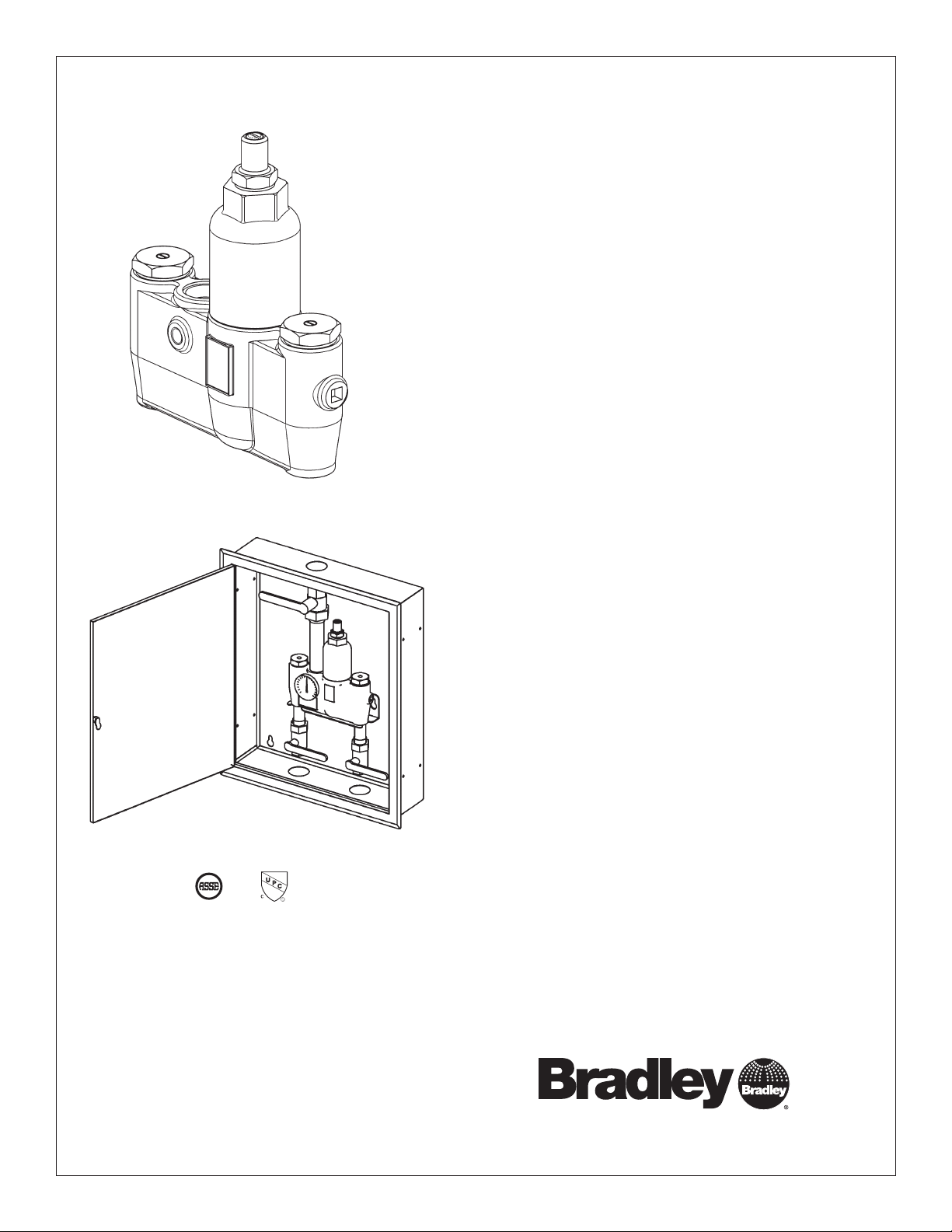
S59-3080
Thermostatic Mixing Valve
with Optional Cabinet
S59-3080RE (with Recess-Mounted
Enamel Cabinet)
S59-3080RS (with Recess-Mounted
Stainless Steel Cabinet)
S59-3080SE (with SurfaceMounted Enamel Cabinet)
S59-3080SS (with SurfaceMounted Stainless Steel Cabinet)
ASSE 1017 & UPC Certified
Table of Contents
Supplies Required ............................ 2
Installation Instructions ........................ 2
Dimensions ................................. 3
Optional Equipment Installation.................. 5
Troubleshooting .............................. 6
Inlet Connections: 1" NPT
Outlet Connection: 1-1/4" NPT
Temperature Range: 90 – 120°F
Maximum Pressure: 125 PSIG
Inlet Temperature Hot: 120 – 200° F
Inlet Temperature Cold: 33 – 80° F
Minimum Temperature Differential
(from valve set point): 20° F
215-1295 Rev. M; ECN 13-09-006
© 2013 Bradley
Page 1 of 8 4/16/2013
P.O. Box 309, Menomonee Falls, WI USA 53052-0309
PHONE 800.BRADLEY (800.272.3539) FAX 262.251.5817
bradleycorp.com
S59-3080 Installation
Installation
THIS
SIDE
UP
Packing List
•
•
•
•
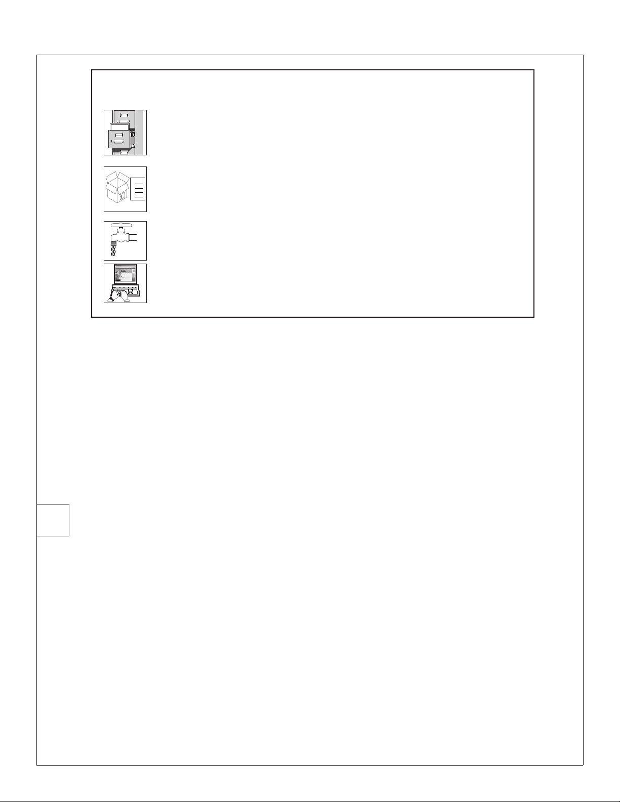
IMPORTANT!
Read this entire installation manual to ensure proper installation.
When finished with the installation, file this manual with the owner or
maintenance department. Compliance and conformity to local codes and
ordinances is the responsibility of the installer.
Separate parts from packaging and make sure all parts are accounted
for before discarding packaging material. If any parts are missing, do not
begin installation until you obtain the missing parts.
Make sure that all water supply lines have been flushed and then
completely turned off before beginning installation. Debris in supply lines
can cause valves to malfunction.
Product warranties may be found under “Products” on our web site at
bradleycorp.com.
Supplies recommended for installation
• Lockable shut-off on the outlet if tempered water is supplied to one or more remote fixtures
• Lockable shut-off on the inlets/supplies
• (6) 3/8" wall anchors and fasteners for surface-mounted cabinet
• (4) 1/4" and (2) 3/8" fasteners (and wall anchors, if necessary) for recess-mounted cabinet
• Unions on all connections to facilitate removal of valve
Tools required for temperature adjustment
• 5/32" Allen wrench
• Blade screwdriver
1
Recessed Cabinet:
1. Rough-in wall opening 24-1/2" W x 28-1/2".
2. Insert the cabinet and secure to wall with four 1/4"
3. Install two 3/8" anchors and screws through the valve
4. Install the valve nipples and one-half of the union ball
5. Insert the valve into the bracket in the cabinet (right
6. Position the wall flange tight to the wall and caulk in
Install Optional Cabinet (If not installing cabinet, skip to Step 2)
Surface-Mounted Cabinet:
1. Measure and mark the cabinet mounting hole locations at
the dimensions shown on next page. Install six 3/8" wall
fasteners properly anchored (supplied by installer.)
bracket in back of the cabinet into a secure brace
(supplied by installer) or into wall. This will support the
valve.
valve using pipe sealant or teflon tape. Install the other
half of the union ball valve onto inlet and outlet pipe.
side goes in first). Continue with the valve installation
procedure.
place.
anchors (supplied by installer).
2. Position the cabinet onto the wall and secure into place
with six 3/8" wall fasteners (supplied by installer).
3. Install the valve nipples and one-half of the union ball valve
using pipe sealant or teflon tape. Then install the other half
of the union ball valve onto the inlet and outlet piping.
4. Insert the valve into the bracket in the cabinet (right side of
the valve goes in first). Continue with the valve installation
procedure.
2 4/16/2013 Bradley • 215-1295 Rev. M; ECN 13-09-006
Installation S59-3080
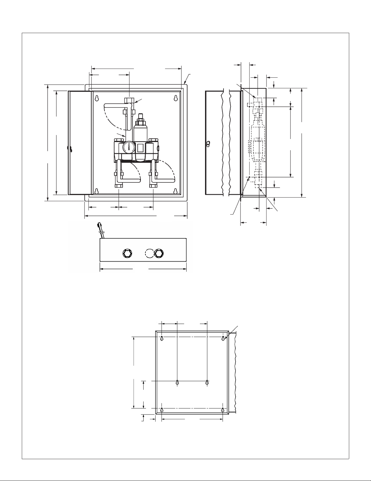
Optional Recessed / Surface Mount Cabinet Dimensions
22-3/4" (578)
8-3/4"
(222)
Door
Union
Ball Valve
26"
(660)
Wall
Flange
0.28" Dia. Holes
(4) each side,
Recess Mount
1-"1/4 NPT
(8) Total for
Front View
26-3/4"
(679)
Door
30"
(762)
10-3/16"
(259)
Nipple
7-5/8"
(194)
2" (51)
Outlet
2"
(51)
6-1/2"
(165)
(mm)
Side View
2-1/4" (57)
2-1/2" (64)
5" (127)
28"
(711)
18"
(457)
2-1/2" (64)
1" NPT
Inlets
Bottom View
Mounting Hole Locations
for Surface Mount
24"
(610)
(51)
24"
(610)
5-1/8"
(130)
9-3/16"
(233)
2"
2"
(51)
9-3/4"
(248)
20"
(508)
Wall Opening:
24-1/2" W x 28-1/2" H
0.47 Dia.
Holes
(6) Places
Bradley • 215-1295 Rev. M; ECN 13-09-006 4/16/2013 3
 Loading...