

Page 1
Installation
DISCONTINUED
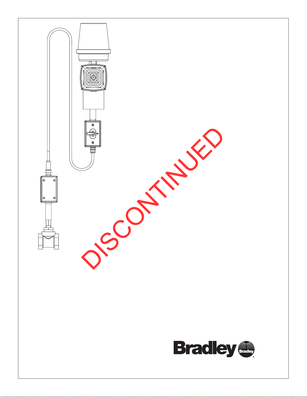
S19-320B (6' cable)
S19-320E (12' cable)
Flow Switch Alarm System with
120/24VAC Transformer
Table of Contents
Pre-Installation Information ......................2
Assembly of Components
Installation
Testing the Alarm System . . . . . . . . . . . . . . . . . . . . . . . 5
Troubleshooting
Strobe Flashtube replacement
Alarm System Maintenance
Remote Sensing Option
...................................4
...............................5
.......................3
...................5
.....................6
........................6
215-693B Rev. J; ECN 13-05-009
© 2013 Bradley
Page 1 of 6 1/30/2013
P.O. Box 309, Menomonee Falls, WI USA 53052-0309
PHONE 800.BRADLEY (800.272.3539) FAX 262.251.5817
bradleycorp.com
Page 2

S19-320B, S19-320E Installation
DISCONTINUED
IMPORTANT
Installation
R
WI 53051
alls,
HENTLICH ZU
WEEK
WÖC
P.O. Box 309, Menomonee F
DAIRE
e(s) each week and sign
UNIT EACH
y malfunctions immediatel
hentlich im
TEST THIS
hrift. Jeglic
DIESES GERÄT 1ST
ESSAI HEBDOMA
Test-operate valv
Report an
Ventil(e) wöc
t immédiatement.
durch Untersc
Test le fonctionnement des v
signe en bas. S'il y à quelqu
un rappor
Date
Datum
Date
114-051
PRÜFEN.
Testbetrieb prüfen,
he Störung sofor
Signed
Unterschrift
below.
bestätigt
t melden.
y.
alves chaque semaine et
e chose qui ne v
Date Signed
Signe
THIS
SIDE
UP
a pas fait
Signed
Signed
Date
Date
P.O. BOX 309, MENOMONEE FALLS, WI 53052-0309 USA
TEL: 1-800-BRADLEY FAX: (262-251-5817)
http://www.bradleycorp.com
Read this installation manual completely to ensure proper installation, then file it with the owner
or maintenance department. Compliance and conformity to drain requirements and other local
codes and ordinances is the responsibility of the installer.
Separate parts from packaging and make sure all parts are accounted for before discarding any
Packing List
•
•
packaging material. If any parts are missing, do not begin installation until you obtain the missing
•
•
parts.
Flush the water supply lines before beginning installation and after installation is complete. Test
the unit for leaks and adequate water flow. Main water supply to the eyewash should be “ON” at
all times. Provisions shall be made to prevent unauthorized shutoff.
The ANSI Z358.1 standard requires an uninterrupted supply of flushing fluid. Bradley plumbed
emergency fixtures require a minimum of 30 psi (0.21 MPa) flowing pressure. Flushing fluid
should be tepid per ANSI Z358.1.
The inspection and testing results of this equipment should be recorded weekly to verify proper
operation. This equipment should be inspected annually to ensure compliance with ANSI Z358.1.
Workers who may come in contact with potentially hazardous materials should be trained
regarding the placement and proper operation of emergency equipment per ANSI Z358.1.
For questions regarding the operation or installation of this product, visit www.bradleycorp.com
or call 1-800-BRADLEY.
Product warranties and parts information may also be found under ”Products” on our web site at
www.bradleycorp.com.
Power should be supplied to the alarm system transformer by no larger than a 120
volt AC, 15 amp branch circuit with a dedicated circuit breaker or fuse and should
not supply power to any other device. Compliance and conformity to local codes and
ordinances is the responsibility of the installer.
2
1/30/2013 Bradley • 215-693B Rev. J; ECN 13-05-009
Page 3

Installation S19-320B, S19-320E
DISCONTINUED
S19-320B and S19-320E Components
6³⁄₈"
(162mm)
¾" NPT
Power
Inlet Hub
22¼"
(565mm)
6"
(152mm)
NEMA 3R Strobe Lamp
Amber (269-525)
Cover, Replacement
(107-460)
Strobe Light Bulb,
Replacement (269-1445)
NEMA 3R Horn
(269-526B)
Product
I.D. Tag
NEMA 3R Switch for Horn
Switch (269-1904)
Box (269-1902)
Electrical Quick
Disconnect Female
with 6' Flexible Cable
(269-524)
or 12' Flexible Cable
(269-1249)
2.9"
(74mm)
Red
Blue
Black
¾" NPT
Hub, Plugged
Brass
Sensor
Body
Brass
Adapter
and Tee
1¼" NPT
Inlet and
Outlet
1.6"
(41mm)
13.8"
(351mm)
Remote Sensing
Red
Blue
Green
Black
Electrical
Connections
Power Supply
Strobe
Green
Red
Black
Green
White
White
NEMA 3R
Junction Box
and Cover
Horn
Socket
White
3" (76mm)
12.4"
(315mm)
3.6"
(91mm)
IMPORTANT!
System is prewired. Installer connects
ONLY ground black and white wires!
Bradley •
215-693B Rev. J; ECN 13-05-009 1/30/2013
Electrical Quick
Disconnect Male
4.7"
(119mm)
Flow Switch
(269-1421)
3
Page 4

S19-320B, S19-320E Installation
DISCONTINUED
Installation
Supplies Required:
• Teflon tape or pipe sealant
• Black, white and green AWG 14 wire to connect alarm to
electric power supply
• ½" conduit and ½" x ¾" adapter bushing for electric power
supply wiring
Step 1: Install the flow switch in the water
supply line
The flow switch will attach to the mounted alarm via a
6-foot waterproof cable. Keep the location for mounting
the alarm in mind when choosing the flow switch
location.
1. Choose a location for mounting the flow switch in a
horizontal run of the water supply line. The inlet and outlet
ports of the flow switch must be a minimum of 6 inches from
any tees or elbows in the water supply line.
2. Mount the flow switch assembly in the water supply line.
• The switch body must be in the vertical position with the
water pipe horizontal.
• The water flow must be in the direction marked by the
arrow on the flow switch body.
• Use teflon tape or pipe sealant (supplied by installer) on
all water pipe connections.
To
Electric
Powe r
Flow
Switch
To
Water
Supply
Alarm
Step 2: Mount alarm assembly to unit
Point the alarm speaker in the direction from which
help is most likely to come.
1. Choose a location for mounting the alarm assembly. The
alarm should be mounted at least 7 feet above ground level
for best visibility.
• The alarm may be mounted directly to the drench shower
piping using the supplied U-bolts and nuts.
• The alarm can also be bolted to a flat surface such
as a wall (hardware for this type of installation is NOT
supplied).
Step 3: Connect alarm to flow switch
1. Connect the flow switch to the alarm by plugging the
prewired cable into the socket provided in the flow switch
junction box. The plug and socket have an alignment pin and
groove which makes for error-free hook-up.
To prevent water condensation from dripping onto the
flow switch, make sure the cable is not taut.
2. Tighten the locking collar on the female cable socket by
rotating it clockwise after plugging in. This makes a good
watertight connection.
Step 4: Complete electrical supply
connections
1. Connect the 24 volt AC power to the Alarm System using
the 14 AWG customer-supplied power cable. Test the alarm
system.
4
1/30/2013 Bradley • 215-693B Rev. J; ECN 13-05-009
Page 5

Installation S19-320B, S19-320E
DISCONTINUED
1¼" to 1"
Reducing
Bushing
required
Piping supplied
by installer
16" (406mm)
min. ceiling
clearance
To 1" Water
Supply
Flow Switch
Horizontal Drench Shower Applications
S19-120 E19-120
S19-120A E19-120A
S19-120BF S19-120ABF
S19-120SS E19-120SS
S19-120SSBF S19-120T
S19-120HFP
Application
S19-310PVC
Flow Switch
optional location
(recommended
location for brass
flow switch is
inside of wall)
To 1¼"
Water
Supply
Piping supplied
by installer
Bradley •
215-693B Rev. J; ECN 13-05-009 1/30/2013
5
Page 6

S19-320B, S19-320E Installation
DISCONTINUED
Test The Alarm System
Testing the alarm for the first time using the drench shower may expose the flow switch to an unnecessary water hammer
since the downstream piping may be empty of water. The flow switch is designed to withstand such a water hammer, but
using the smaller eyewash flow is recommended.
1. Apply power to the alarm branch circuit. The alarm should remain in the "OFF" position.
2. Make sure the alarm horn cut-out switch is in the "ON" position. This switch is located on the PVC tee beneath the alarm.
3. Open the eyewash valve. The alarm should sound and the strobe light flash shortly after water flows from the system.
4. Use the alarm horn cut-off switch to silence the horn. Flipping the switch down one or two clicks (either the horizontal or
DOWN position will work) should shut off the horn but allow the strobe light to keep flashing.
5. Shut off the eyewash flow valve. The strobe light should stop flashing.
6. Reset the alarm horn cut-off switch to its uppermost "ON" position.
7. Repeat the tests in procedures 1-6 above, this time using the drench shower only.
Troubleshooting
1. If the alarm (horn and strobe light) does not operate when water flows:
• Check to make sure the circuit breaker or fuse is supplying power to the alarm.
• Check to make sure the direction of water flow corresponds to the arrow on the flow switch body.
• Check to make sure the water flow is sufficient (2.4 gallons per minute is required).
• Check all electrical connections, including the power supply and the quick-connect cable from the alarm to the flow switch.
Strobe flashtube replacement
1. Loosen the locking band and remove the clear plastic dust cover from the top of the strobe light.
2. Loosen (but do not remove) the three screws holding the amber dome in place. Rotate the dome slightly clockwise and
remove the dome.
3. Remove the flashtube assembly by simply unplugging it from the top of the strobe light.
4. Replace the flashtube assembly with a new one BUT avoid touching the flashtube glass with your fingers. Be sure the
flashtube assembly is firmly plugged into the socket.
5. Reattach and tighten the amber dome.
6. Reattach and tighten the clear dust cover.
7. Test the alarm as described in "Test the Alarm System."
Alarm system maintenance
The Bradley Alarm System is designed to be virtually maintenance free. An occasional damp cloth wiping of the clear dust cover
is all that is needed to ensure maximum visual attention-getting ability.
The alarm horn is factory-set at the loudest possible sound level, 103 decibels at 10 feet. This sound level will attract attention in
shop areas with loud background noise levels or at large distances outdoors. If the alarm is used in a more quiet environment or
over shorter distances, the sound level is easily adjustable to lower levels (down to 78 decibels at 10 feet) with a simple external
adjustment.
• Use 1/16" Allen wrench to adjust the sound to the appropriate alerting level. The adjusting hex screw is located on the front
centerline of the horn grille about an inch from the bottom. Turning the hex screw clockwise quiets the horn.
Remote Sensing Option
If remote sensing is wanted, remove the pipe plug from the back of the junction box. Connect the extra black wire (common
to both switch arrangements) and the blue wire (normally open switch arrangement) or red wire (normally closed switch
arrangement) to your application per local electrical codes. The switch is rated at 5 amps at 120 volts and is isolated from the
contacts used by the alarm system. Your connection should be water tight.
6
1/30/2013 Bradley • 215-693B Rev. J; ECN 13-05-009
 Loading...