

Page 1
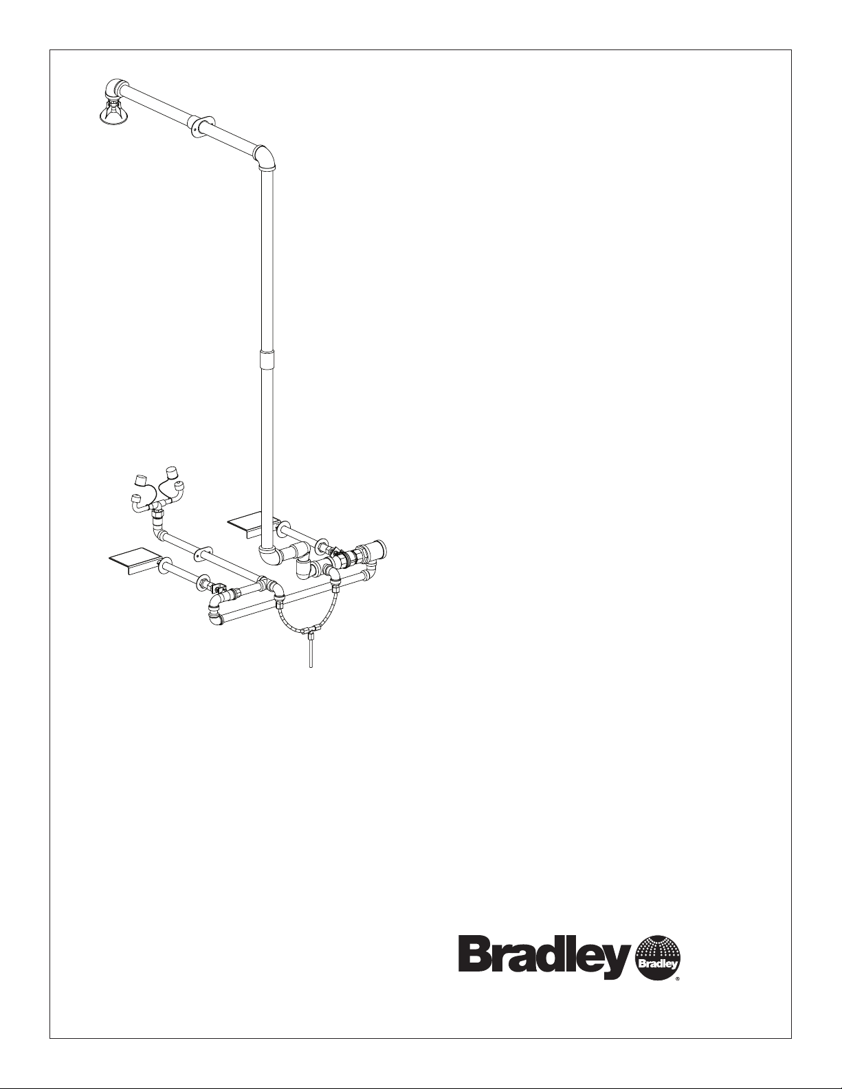
Installation
S19-310TW8
S19-310TW12
S19-310TW18
Frostproof Combination Drench
Shower and Eyewash
Table of Contents
Pre-Installation Information ..........................2
Dimensions ......................................3
Installation .......................................4
Assembly of Components ...........................5
Parts List ........................................6
215-1474 Rev. J; ECN 12-05-016G
© 2012 Bradley
Page 1 of 6 11/20/2012
P.O. Box 309, Menomonee Falls, WI USA 53052-0309
PHONE 800.BRADLEY (800.272.3539) FAX 262.251.5817
bradleycorp.com
Page 2

S19-310TW8, S19-310TW12, S19-310TW18 Installation
IMPORTANT
Installation
R
WI 53051
alls,
HENTLICH ZU
WEEK
WÖC
P.O. Box 309, Menomonee F
DAIRE
e(s) each week and sign
UNIT EACH
y malfunctions immediatel
hentlich im
TEST THIS
hrift. Jeglic
DIESES GERÄT 1ST
ESSAI HEBDOMA
Test-operate valv
Report an
Ventil(e) wöc
t immédiatement.
durch Untersc
Test le fonctionnement des v
signe en bas. S'il y à quelqu
un rappor
Date
Datum
Date
114-051
PRÜFEN.
Testbetrieb prüfen,
he Störung sofor
Signed
Unterschrift
below.
bestätigt
t melden.
y.
alves chaque semaine et
e chose qui ne v
Date Signed
Signe
THIS
SIDE
UP
a pas fait
Signed
Signed
Date
Date
P.O. BOX 309, MENOMONEE FALLS, WI 53052-0309 USA
TEL: 1-800-BRADLEY FAX: (262-251-5817)
http://www.bradleycorp.com
Packing List
•
•
•
•
Read this installation manual completely to ensure proper installation, then file it with the
owner or maintenance department. Compliance and conformity to drain requirements and
other local codes and ordinances is the responsibility of the installer.
Separate parts from packaging and make sure all parts are accounted for before discarding
any packaging material. If any parts are missing, do not begin installation until you obtain the
missing parts.
Flush the water supply lines before beginning installation and after installation is complete.
Test the unit for leaks and adequate water flow. Main water supply to the eyewash should be
“ON” at all times. Provisions shall be made to prevent unauthorized shutoff.
The ANSI Z358.1 standard requires an uninterrupted supply of flushing fluid. Bradley plumbed
emergency fixtures require a minimum of 30 PSI (0.21 MPa) flowing pressure. Flushing fluid
should be tepid per ANSI Z358.1.
The inspection and testing results of this equipment should be recorded weekly to verify
proper operation. This equipment should be inspected annually to ensure compliance with
ANSI Z358.1.
Workers who may come in contact with potentially hazardous materials should be trained
regarding the placement and proper operation of emergency equipment per ANSI Z358.1.
For questions regarding the operation or installation of this product, visit www.bradleycorp.
com or call 1-800-BRADLEY.
Product warranties and service parts information may also be found under ”Products” on our
web site at www.bradleycorp.com.
2
11/20/2012 Bradley • 215-1474 Rev. J; ECN 12-05-016G
Page 3

Installation S19-310TW8, S19-310TW12, S19-310TW18
S19-310TW Dimensions
Ø 3.1"
(78.7mm)
16"
(406mm)
53¼"
(1352mm)
3⁷⁄₈"
(98mm)
(dimension will
increase with
varying wall
thicknesses)
Wall Thickness Model No.
0"−8" S19-310TW8
8"−12" S19-310TW12
12"−18" S19-310TW18
Use valve sub-assembly (Item 15)
to mark and drill valve stem holes.
8"
(203mm)
1¼" NPT
Supply Inlet
12"
(305mm)
48¾"
(1238mm)
36"
(914mm)
to floor
5⁵⁄₈"
(143mm)
All dimensions assume standard thread
engagement. Variations in manufacturing
allow for +/- 1⁄8" (3mm) per threaded joint.
To find the tolerance of a dimension, add
the number of thread joints in between a
dimension and multiply it by 1⁄8" (3mm).
Bradley • 215-1474 Rev. J; ECN 12-05-016G 11/20/2012
3
Page 4

S19-310TW8, S19-310TW12, S19-310TW18 Installation
Installation
Supplies Required:
• Teflon tape and pipe sealant
• Piping to 1¼" NPT water supply inlet
• Adequate supply pipe supports
• Minimum 4" (102mm) drain to accommodate 30 gallons (115 liters) per minute discharge for drench
shower waste
• OPTIONAL: Sign-mounting hardware
Local codes may require the installation of a backflow prevention valve to complete proper installation.
Compliance with local codes is the responsibility of the installer. Valve must be tested annually to verify that
it is functioning properly. Backflow prevention valves are not included with the fixture and may be supplied by
the contractor or purchased from Bradley Corporation.
IMPORTANT! Do not rely on Bradley’s Combination Unit to support supply piping.
Step 1: Assemble drench shower and eyewash components
1. From the outside of the building, drill a 1" dia. hole in the wall 36" up from the ground floor for the eyewash
piping. Use the sub-assembly (Item 15) to measure, mark and drill two 1³⁄₈" dia. holes for the valve operating
stems.
This unit has been designed to accommodate varying wall thicknesses. When installing the operating stem
support sleeve (Item 27), make sure that a minimum 5⁄8" of threaded pipe protrudes from the wall.
2. Assemble the two valve stems as shown on page 5 and connect the stems to the assembly through the holes
in the wall.
3. Secure the assembly to the wall with adequate supports supplied by installer. Make sure that Item 14 is pitched
a minimum of ½" toward the building to allow for proper weep valve drainage.
4. Connect Items 4, 8, 9 and another Item 9 (as shown on page 5) and attach them to Item 15.2.
5. Mark and drill a 1³⁄₈" dia. hole for the shower pipe.
6. Assemble the rest of the unit as shown on page 5.
Step 2: Connect water supply
1. Connect water supply piping to the 1¼" NPT inlet (piping supplied by installer). Provide adequate supports
(supplied by installer) for supply pipe using pipe hangers or other means.
2. Run the drain’s ⁵⁄₁₆" tubing to an adequate drain containment.
3. Hang the safety sign from the unit with the curtain hooks provided (or mount it to the wall using sign-mounting
hardware by installer).
4
11/20/2012 Bradley • 215-1474 Rev. J; ECN 12-05-016G
Page 5

Installation S19-310TW8, S19-310TW12, S19-310TW18
Assembly of Components
8
3
1
4
5
7
NOTE: Use
teflon tape
only.
2
12
P.O. BOX 309, MENOMONEE FALLS, WI 53052-0309 USA
TEL: 1-800-BRADLEY FAX: (262-251-5817)
http://www.bradleycorp.com
9
34
33
22
23
26.1
24
16
25
27
26
29
25
35
36
14
6
24
26.1
21
23
22
20
15.41
19
15.4
15.11
15.13
15.14
15.2
15.15
8
9
4
15.3
15.12
15.5
17
15.1
15.7
22
23
26.1
24
25
27
26
15.10
15.9
15.6
15.8
13
13
30
30
31
18
25
15.11
24
26.1
28
11
29
23
22
32
15.61
Bradley • 215-1474 Rev. J; ECN 12-05-016G 11/20/2012
5
Page 6

S19-310TW8, S19-310TW12, S19-310TW18 Installation
Parts List
Item Part No. Qty. Description
1 S24-188 1 Showerhead, Plastic
2 151-001 2 Hook
3 113-1107 1 Pipe, 1" NPT x 14"
4 169-1027 2 Coupling, 1" NPT
5 150-212 1 Escutcheon, Shower Pipe
6 150-213 1 Escutcheon, Eyewash Pipe
7 113-1108 1 Pipe, 1" NPT x 11½"
(S19-10TW8)
113-1109 1 Pipe, 1" NPT x 15½"
(S19-10TW12)
113-1110 1 Pipe, 1" NPT x 21½"
(S19-10TW18)
8 169-847 2 Elbow, 1" NPT
9 113-1112 2 Pipe, 1" NPT x 24"
11 140-720 1 Bracket, 1" Ball Valve Adapter
12 114-052 1 Safety Sign
13 S29-068 2 Weep Valve Assembly
14 113-1116 1 Pipe, ½" NPT x 18¾"
(S19-10TW8)
113-1117 1 Pipe, ½" NPT x 22¾"
(S19-10TW12)
113-1118 1 Pipe, ½" NPT x 28¾"
(S19-10TW18)
15 S08-369 1 Valve Sub-Assy, Eyewash/
Shower
15.1 169-723 2 1" Street Elbow 90°
15.2 169-847 1 Elbow, 1" NPT
15.3 113-1113 1 Pipe, 1" x 3"
15.4 S27-282 1 ½" Ball Valve with Nut
15.41 110-215 1 Nut (only)
15.5 169-838 1 Tee, ½" NPT
15.6 S27-278 1 1" Ball Valve with Nut
15.61 110-214 1 Nut (only)
15.7 169-840 1 Tee, 1" x 1" x ½"
15.8 113-935 2 Pipe, 1" NPT x 1½"
15.9 269-1721 1 Reduc’g Bushing, 1¼" x 1"
15.10 169-841 1 Tee, 1¼" x ½"
Item Part No. Qty. Description
15.11 169-025 2 90° Street Elbow ½" NPT
15.12 113-1114 1
15.13 113-1084 1 Pipe, ½" NPT x 1½"
15.14 169-839 1 Elbow ½" NPT
15.15 113-1115 1 Pipe, ½" NPT x 4¼"
16 S08-361 1 Handle, Eyewash
17 S08-360 1 Handle, Shower
18 269-1720 1
19 153-372R 1 Adapter, ½" Ball Valve
20 142-002DA 1
21 128-151 1 Adapter, ½" Ball Valve Handle
22 161-036 4
23 142-002BK 4
24 110-191 4 Nut, ½"-14 NPS Connector
25 142-002CB 4
26 S21-067 2 Rod, Operating (S19-310TW8)
S21-067A 2 Rod, Operating (S19-310TW12)
S21-067B 2 Rod, Operating (S19-310TW18)
26.1 132-042 4 Clip, Retaining
27 113-006NN 2 Sleeve, Operating Rod
113-006NR 2 Sleeve, Operating Rod
113-006NU 2 Sleeve, Operating Rod
28 128-164 1 Adapter, 1" Ball Valve Handle
29 110-115 2 Nut, ½" NSPM
30 269-881 2
31 R68-600015 4 ft.
32 142-002DC 1
33 S05-091 1 Eyewash Yoke
34 107-371 2 Tethered Dust Cover
35 S21-077 1 Stem
36 169-1069 1
Pipe, ½" NPT x 23¹⁷⁄₃₂"
Tee, ⁵⁄₁₆"Hose, Nylon Union
Lockwasher, ⁵⁄₁₆" Internal Tooth
Nut, Hex ⁵⁄₁₆"-18 Stn. Steel
Lockwasher, ⁵⁄₁₆" Stn. Steel
Washer, ⁷⁄₈" x 2" Stainless Steel
(S19-310TW8)
(S19-310TW12)
(S19-310TW18)
ElbowConnector, ¼" NPT, ⁵⁄₁₆"
Tube
Tube, ⁵⁄₁₆" Polyethylene
Lockwasher, ³⁄₈" Internal Tooth
Elbow, ½" x ³⁄₈"
6
11/20/2012 Bradley • 215-1474 Rev. J; ECN 12-05-016G
 Loading...