

Bradley Corporation S19-260 Installation Manual
Installation
S19-260
Recessed Deck-Mounted Eye/Face
Wash
Douche oculaire/faciale de comptoir
encastrée
Accesorio para el lavado de los ojos/
rostro con montaje de platforma
Table of Contents
Pre-Installation Information ...................... 2
Installation Instructions ......................... 3
Assembly of Components ....................... 4
Parts List .................................... 4
Table des matières
Avant l’installation ............................. 5
Instructions d’installation ........................ 6
Assemblage des composantes ................... 7
Liste des pièces............................... 7
Contenido
Información previa a la instalación ................ 8
Instrucciones de instalación ..................... 9
Montaje de los componentes ................... 10
Lista de piezas .............................. 10
215-770 Rev. L; ECN 12-05-003C
© 2012 Bradley
Page 1 of 10 10/22/2012
P.O. Box 309, Menomonee Falls, WI USA 53052-0309
PHONE 800.BRADLEY (800.272.3539) FAX 262.251.5817
bradleycorp.com
S19-260 Installation
IMPORTANT
Installation
R
WI 53051
alls,
HENTLICH ZU
WEEK
WÖC
P.O. Box 309, Menomonee F
DAIRE
e(s) each week and sign
UNIT EACH
y malfunctions immediatel
hentlich im
TEST THIS
hrift. Jeglic
DIESES GERÄT 1ST
ESSAI HEBDOMA
Test-operate valv
Report an
Ventil(e) wöc
t immédiatement.
durch Untersc
Test le fonctionnement des v
signe en bas. S'il y à quelqu
un rappor
Date
Datum
Date
114-051
PRÜFEN.
Testbetrieb prüfen,
he Störung sofor
Signed
Unterschrift
below.
bestätigt
t melden.
y.
alves chaque semaine et
e chose qui ne v
Date Signed
Signe
THIS
SIDE
UP
a pas fait
Signed
Signed
Date
Date
P.O. BOX 309, MENOMONEE FALLS, WI 53052-0309 USA
TEL: 1-800-BRADLEY FAX: (262-251-5817)
http://www.bradleycorp.com
Packing List
•
•
•
•
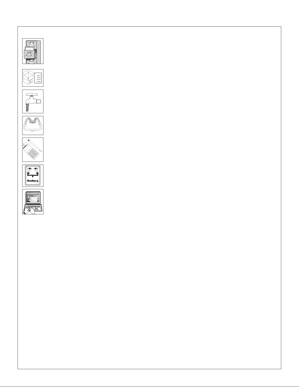
Read this installation manual completely to ensure proper installation, then file it with the
owner or maintenance department. Compliance and conformity to drain requirements and
other local codes and ordinances is the responsibility of the installer.
Separate parts from packaging and make sure all parts are accounted for before discarding
any packaging material. If any parts are missing, do not begin installation until you obtain
the missing parts.
Flush the water supply lines before beginning installation and after installation is complete.
Test the unit for leaks and adequate water flow. Main water supply to the eye/face wash
should be “ON” at all times. Provisions shall be made to prevent unauthorized shutoff.
The ANSI Z358.1 standard requires an uninterrupted supply of flushing fluid. Bradley
plumbed emergency fixtures require a minimum of 30 PSI (0.21 MPa) flowing pressure.
Flushing fluid should be tepid per ANSI Z358.1.
The inspection and testing results of this equipment should be recorded weekly to verify
proper operation. This equipment should be inspected annually to ensure compliance with
ANSI Z358.1.
Workers who may come in contact with potentially hazardous materials should be trained
regarding the placement and proper operation of emergency equipment per ANSI Z358.1.
For questions regarding the operation or installation of this product, visit www.bradleycorp.
com or call 1-800-BRADLEY.
Product warranties may also be found under “Products” on our web site at
www.bradleycorp.com.
2
10/22/2012 Bradley • 215-770 Rev. L; ECN 12-05-003C
Installation S19-260
Installation Instructions
NOTICE! Avoid cleaners containing organic solvents,
alcohols, and hydrocarbons. Rinse with water
after cleaning.
Supplies Required:
• Supply piping to ½" NPT water supply inlet
• Drain piping to 1¼" NPT
• Tailpiece and trap to conform to local codes
• Sign-mounting hardware
Local codes may require the installation of a backflow
prevention valve to complete proper installation. Compliance
with local codes is the responsibility of the installer. Valve
must be tested annually to verify that it is functioning
properly. Backflow prevention valves are not included
with the fixture and may be supplied by the contractor or
purchased from Bradley Corporation.
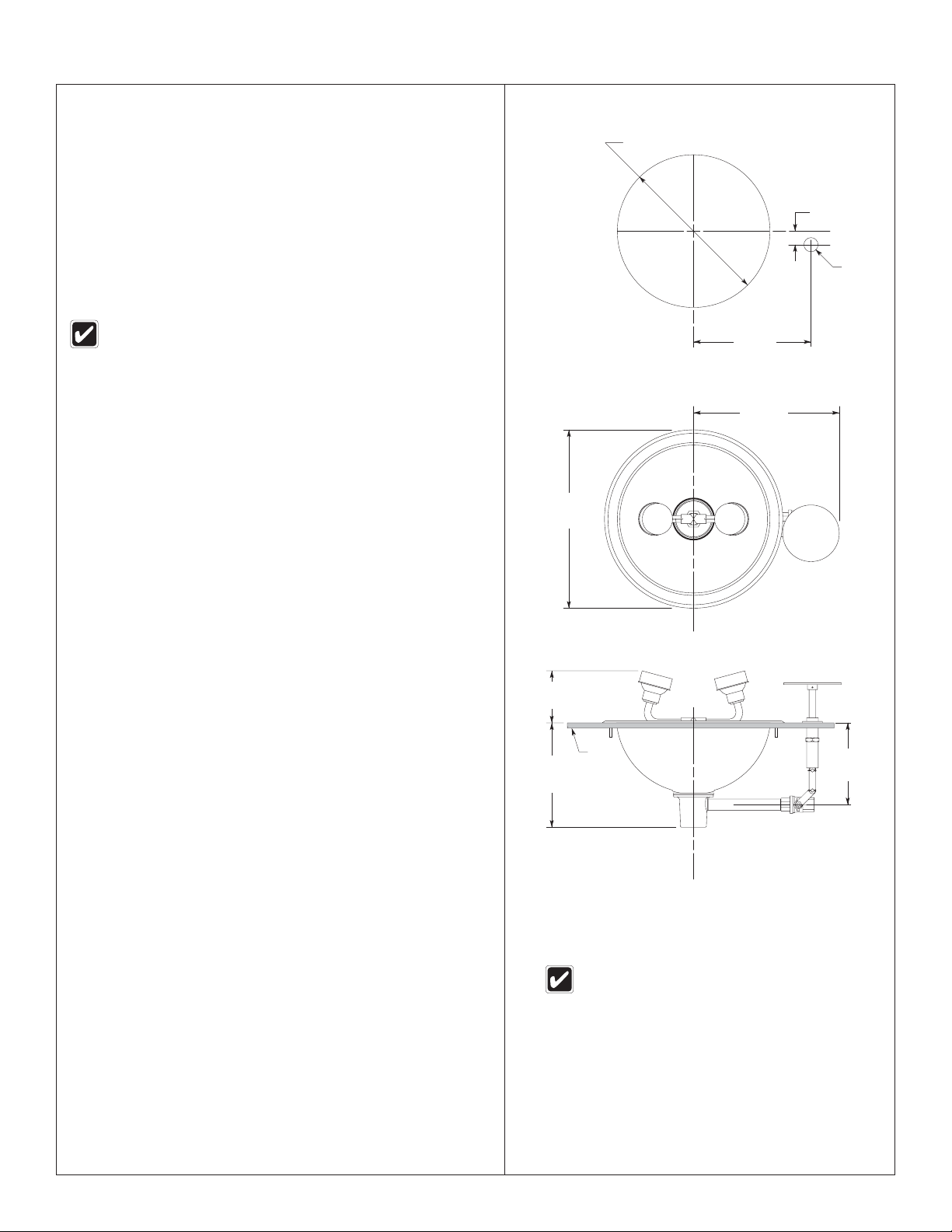
Step 1: Prepare deck
1. Select the desired location for the eyewash on the deck and
make the necessary cutouts per the rough-ins.
Step 2: Install eyewash
IMPORTANT! To ensure proper operation, the handle
assembly should be in the “up” position
while the ball valve is closed. To make the
adjustment, rotate the handle assembly
180° and reattach to the ball valve.
1. Assemble the valve and pipe as shown on page 4 and
connect it to the bowl.
2. Lower the complete assembly through the cutout and secure
it to the deck with the mounting hardware provided.
3. Attach the eye/face wash to the bowl.
4. Install the operating rod mechanism through the hole
provided.
5. Attach the operating lever to the valve and secure.
13⁵⁄₈"
(346mm)
3⁷⁄₈" (98mm)
7¾"
(197mm)
Ø 12⁷⁄₈" (327mm)
1" (25mm)
Ø ⁷⁄₈"
(22mm)
9¼"
(235mm)
11½"
(292mm)
6"
(152mm)
Step 3: Connect water supply
1. Connect the water supply piping to the ½" NPT inlet on the
unit (piping supplied by installer).
2. Connect the drain piping to the 1¼" NPT drain outlet on the
unit (piping supplied by installer).
3. Mount the safety sign to a wall using sign-mounting
hardware (supplied by installer).
4. Open the water supply lines. Test for leaks and adequate
water flow.
Bradley • 215-770 Rev. L; ECN 12-05-003C 10/22/2012
All dimensions assume standard thread
engagement. Variations in manufacturing allow
for +/- 1⁄8" (3mm) per threaded joint. To find
the tolerance of a dimension, add the number
of thread joints in between a dimension and
multiply it by 1⁄8" (3mm).
3
 Loading...