

Page 1
SUPPLEMENT – VENTING INSTRUCTIONS FOR INSTALLATION AND OPERATING INSTRUCTION MANUALS
WARNING
The venting system must be properly installed. Failure to properly install the vent system could result in property
damage, personal injury, or death.
DO NOT install damaged venting system components. If damage is evident then please contact the supplier where
the water heater or venting system components were purchased for replacement parts.
Use only the vent terminals provided or factory authorized terminals for venting this water heater.
The water heater requires its own separate venting system. Do not connect the exhaust vent into an existing vent pipe
or chimney.
All of the exhaust venting connections must be leak checked with a soap solution upon initial start-up of the water
heater. Any leaks must be repaired before continuing operation of the water heater.
Do not terminate the venting where noise from the exhaust or intake will be objectionable. This includes locations
close to or across from windows and doors. Avoid anchoring the vent and intake pipes directly to framed walls, floors,
or ceilings unless rubber isolation pipe hangers are used. This prevents any vibrations from being transmitted into the
living spaces.
Do not exceed the venting distances or the number of elbows listed in the instruction manual supplied with the water
heater. Exceeding the maximum venting distances may cause the water heater to malfunction or cause an unsafe
condition.
DO NOT operate this water heater until the venting installation is complete and the piping completed. Failure to
complete installation before operation can result in property damage, personal injury, or death.
DO NOT install Duravent Polypro venting components with any other manufacturer’s vent components. Duravent
components must be used exclusively throughout the entire venting system from the water heater coupling or vent
connection to the outside wall or ceiling near the vent terminal location.
This supplement is intended only for additional information for installing Duravent Polypro single wall venting system
and the instruction manual supplied with the water heater must be followed for the detailed information provided for the
venting system installation.
238-48384-00, 238-44727-00, 238-44445-00, 238-48144-00, 238-47936-00, 238-45917-00, 238-45637-00,
238-47448-00, 238-48071-00, 238-49060-00, AND 238-47707-00 FOR HIGH EFFICIENCY CONDENSING
COMMERCIAL, COMMERCIAL POWER DIRECT VENT, COMMERCIAL POWER VENT, RESIDENTIAL POWER
DIRECT VENT, and RESIDENTIAL POWER VENT MODEL SERIES
INSTALLATION OF DURAVENT POLYPRO® SINGLE WALL POLYPROPYLENE VENTING SYSTEMS
This supplement is for the installation of polypropylene single wall venting system manufactured by M&G DuraVent, Inc.
The DuraVent Polypro venting system is a CSA approved alternative to the PVC, ABS, and CPVC venting components for
the High Efficiency Commercial Condensing, Commercial Power Direct Vent, Residential Power Direct Vent, Commercial
Power Vent and Residential Power Vent model series.
The DuraVent venting system components are ULC S636 approved and listed by a recognized agency and may be
installed in the U.S. and Canada. All components used must be from the same manufacturer and are designed for use
with the above noted products. The DuraVent components may be purchased from plumbing supply distributors. The
vent size diameter and maximum vent lengths must be followed as detailed in the Installation and Operating Instruction
Manual that was supplied with the water heater. Thoroughly read and understand the venting section of the instruction
manual supplied with the water heater before proceeding with the following instructions in this supplement. The vent
terminals supplied with the water heater or the factory approved accessory vent terminal kits must be used with this
venting system.
1 238-50320-00A 3/13
Page 2
Step 1: Thoroughly read and understand the venting section of the Installation and Operating Instruction Manual that
WARNING
Use only water for lubricating the gaskets and pipe ends to allow easy insertion. DO NOT use any other kind of
lubricant, since deterioration of the gasket may result, which may allow dangerous flue gases to leak into the room.
If the vent pipe needs to be disassembled after the gasket has dried, wet the joint thoroughly to loosen the
connection.
was supplied with the water heater before determining the location of the water heater and the vent terminals. Locate
the water heater for the shortest practical vent length to the outside. Measure the total venting distance required to
reach the outside wall or roof. Determine the diameter of the venting components to use for the length of vent pipe
(and combustion air supply for direct vent models) required by referring to the venting tables in the instruction manual
for the maximum vent length for each diameter pipe size. Obtain all the necessary venting system components for the
installation.
Step 2: Before installation, inspect each vent component for damage making sure the gaskets for each component are
fully intact and in undamaged condition. Do not attempt to install or repair damaged components. If a gasket is
damaged, these are available from the supplier of DuraVent components. Do not use gaskets from another
manufacturer and do not try to repair the gasket.
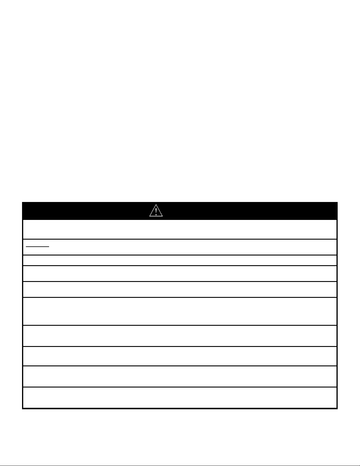
Step 3: A DuraVent PVC to Polypropylene adapter (referred by DuraVent as Appliance Adapters, 2PPS-AD, 3PPS-AD, or
4PPS-AD) must be used to connect into a PVC coupling or tee (Commercial and Residential Power Direct Vent air intake
connections), condensate elbow (High Efficiency Commercial Condensing models) or the exhaust outlet adapter for
Commercial Power Vent and Residential Power Vent models. To make the insertion of the gasketed fittings into the
coupling easier, rotate the joints slightly and use water to lubricate the gaskets. DO NOT use any other kind of lubricant.
Wet the gasket surface and inside of the coupling using your finger or wet paper towel and insert the male end of the
adapter with the exterior gasket into the coupling, condensate elbow or exhaust outlet adapter connection. If a larger
vent diameter size is to be used, use the appropriately sized reducer coupling first on the water heater intake or exhaust
vent connection as detailed in the installation manual supplied with the water heater. See the following photos.
High Efficiency Condensing Commercial Models: Use the appropriate primer and cement (refer to venting section of
instruction manual with water heater) for cementing a PVC coupling (not supplied with water heater) to the end of the
PVC air intake pipe connection. Using your finger, wet with water the male gasketed end of the DuraVent PVC to
PolyPro adapter and fully insert into the air intake coupling. Loosen the DuraVent adapter connector clamp (PPS-PAC)
and install over the PVC coupling. See following photos.
2 238-50320-00A 3/13
Page 3
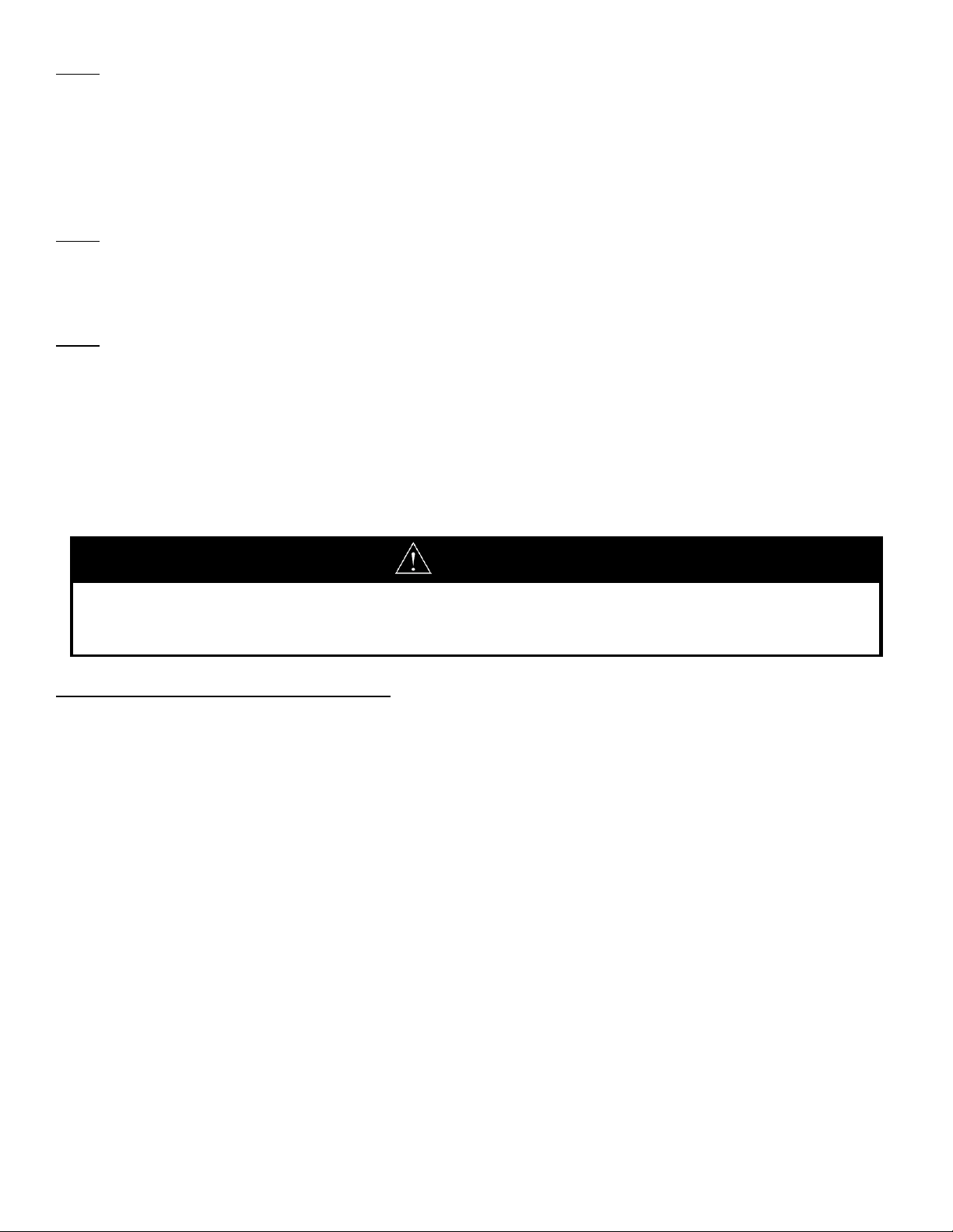
Install PVC pipe coupling over air intake pipe connection
WARNING
DuraVent Adapter Connector Clamps (p/n: PPS-PAC) MUST be properly
installed to secure the PVC Vent Adapter. DO NOT operate the vent system
without first installing the Flue Adapter Connector Clamps.
Water Heater PVC Air Intake
Pipe. Use appropriate
solvent and cement to
cement coupling to pipe.
PVC Pipe Coupling (not
supplied with water heater)
Wet gasket using water
with finger
Male Gasketed end of PVC
adapter
Flue Clamp band fit over PVC Adapter
shoulder and PVC Coupling. Tighten
clamp screws securely with screwdriver.
and cement to pipe using appropriate solvent and cement. Wet gaskets of DuraVent PVC Adapter using finger.
Insert male gasketed end of DuraVent
PVC adapter into PVC pipe coupling. Install DuraVent Adapter Connector Clamp (PPS-PAC) over the
PVC coupling so that clamp brackets secure the shoulder of PVC
adapter fitting. Tighten clamp screws securely.
3 238-50320-00A 3/13
Page 4
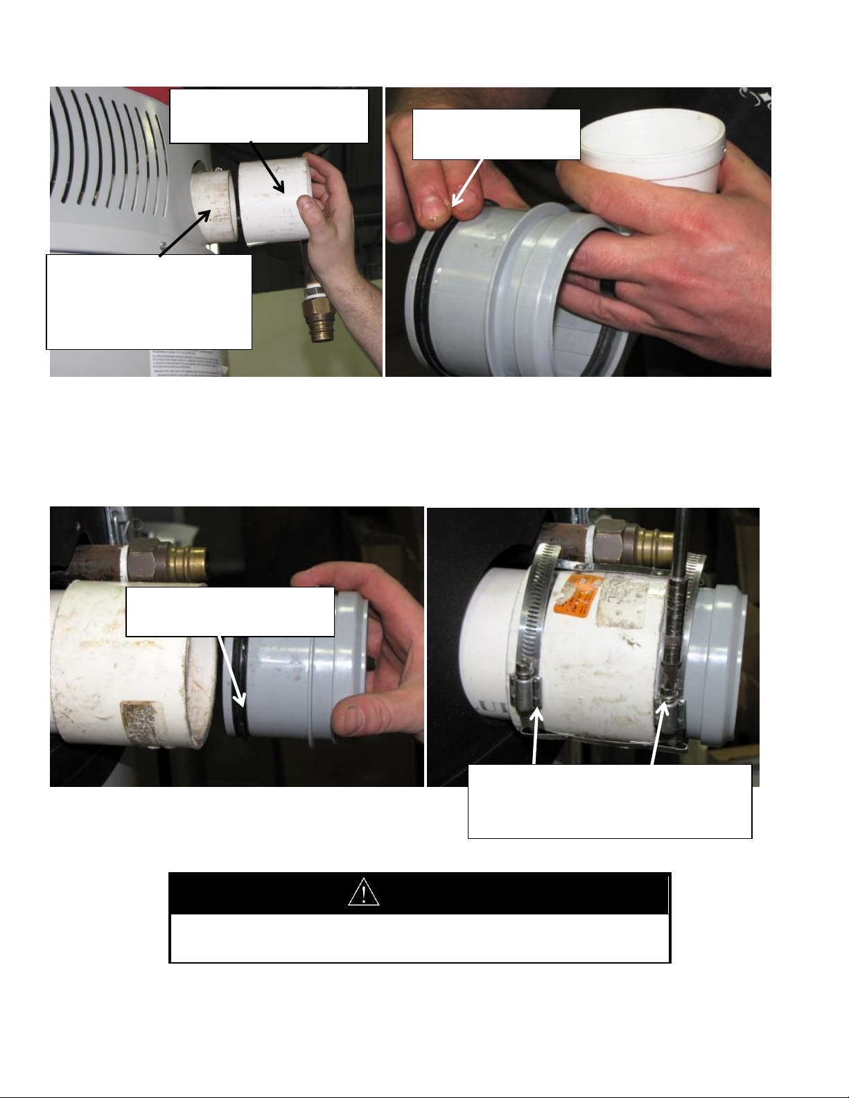
Condensate Elbow
Tighten Connector Clamp
Wet gasket with water using finger of PVC Adapter
PVC Adapter into Elbow
Connector Clamp
around PP pipe
Install Connector Clamp over Condensate Elbow
For High Efficiency Commercial Model series exhaust connection, wet outside gasket with finger and insert PVC adapter
into the condensate elbow. Insert DuraVent PVC Adapter fitting into Condensate Elbow as shown.
Install DuraVent Connector Clamp around outside of Tighten Connector Clamp Screw to secure PVC Adapter and
Condensate Elbow as shown. Adapter and Vent Pipe into condensate Elbow.
4 238-50320-00A 3/13
Page 5

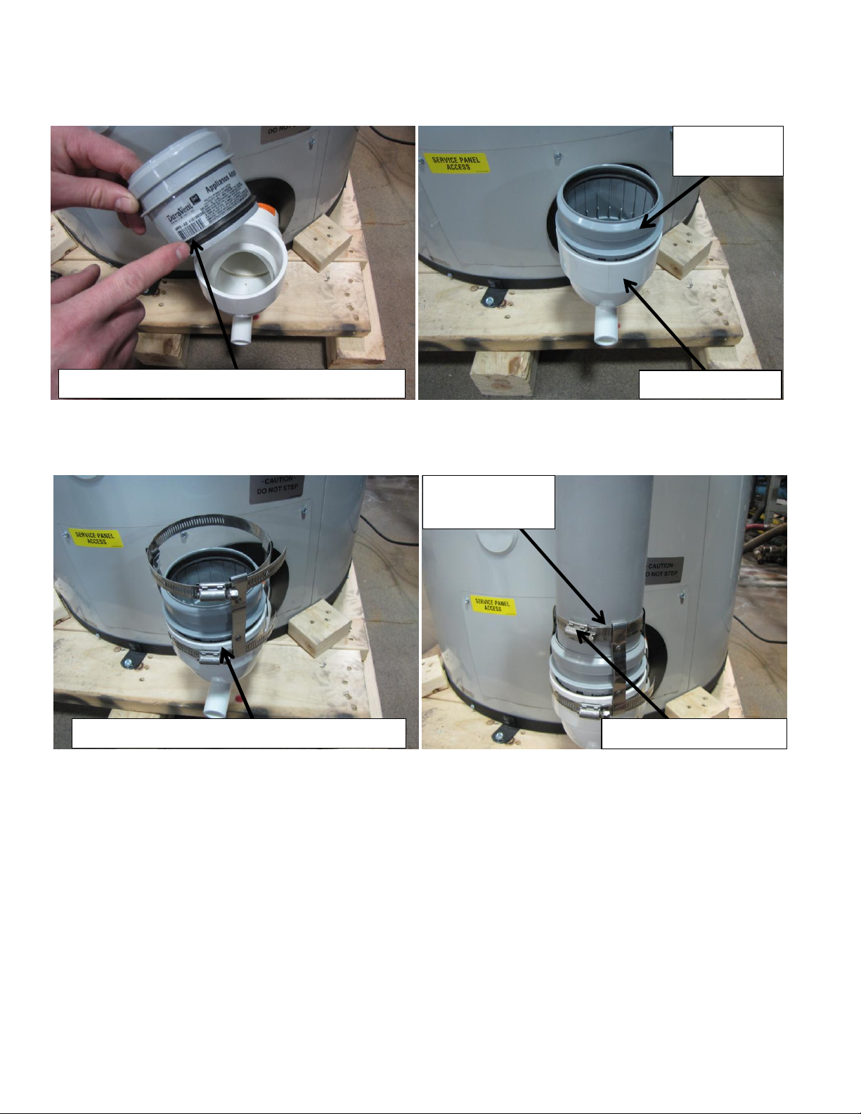
Commercial and Residential Power Direct Vent / Power Vent Models:
For installation of commercial and residential power
vent models, install the male end of the PVC to
PolypPro adapter into the air intake pipe tee as shown.
Install the adapter connector clamp over the PVC adapter.
Then install the elbow or vent pipe section into the PVC
adapter. Tighten the clamp bands of the adapter connector
to the air intake tee and pipe elbow or straight pipe section to
secure vent pipe to the water heater air intake tee as shown
below.
Air Intake Pipe Tee
Adapter Connector Clamp – Fits over Air Intake
Tee and next vent pipe section as shown.
PVC Adapter
Fitting
5 238-50320-00A 3/13
Page 6

For the exhaust venting for all power vent and power direct For Commercial Power Direct Vent models, insert
Install the Adapter Connector Clamp over the PVC adapter and install the elbow or next section of straight pipe into
the PVC adapter. Then tighten the clamp bands of the Adapter Connector around the Exhaust Outlet Adapter and
Elbow to secure venting system.
Exhaust Outlet Adapter with
clamp for residential power
vented models. Tighten clamp.
Exhaust Outlet Adapter for
Power Direct Vent Commercials.
Tighten clamp screws to secure
vent pipe elbow to exhaust
outlet adapter.
vent models, insert the PVC Adapter into the Exhaust Outlet PVC Adapter into Exhaust Outlet Adapter.
Adapter. On residential models, tighten the clamp to secure
the PVC Adapter.
6 238-50320-00A 3/13
Page 7

Step 4: Using a finger or paper towel, wet with water the inside gasket of the PVC adapter and the male end (without
WARNING
DO NOT operate vent system without
properly installing Locking Bands.
PVC Adapter
Locking Band first inserted over end of
vent pipe section
Use a twisting motion to insert male end of
vent pipe section into PVC Adapter
Push hook of Locking Band over the lip of
the joint to secure the vent pipe
gasket) of the elbow or straight section of pipe for running the exhaust or intake pipe from the water heater.
Steel joint Locking Bands (available from DuraVent supplier) must be used at each pipe joint. The connector rings ensure
that the joints do not separate under heavy loads. These connector rings must be used to comply with ULC-S636
requirements. See following photo with the joint connector attached to the pipe sections.
Insert a Locking Band over the male end of the vent pipe section with the hook and leg facing the joint. Insert the male
end of the elbow or straight section into the PVC adapter. Use a twisting motion while pushing the male end of the pipe
or elbow into the PVC adapter to fully seat into the gasket. The male end of the pipe or elbow must always point toward
the water heater.
Secure Locking Band to connection joint by sliding the hook over the lip of the joint as shown below.
7 238-50320-00A 3/13
Page 8

WARNING
Make sure pipe sections are fully inserted into the PVC adapter and/or gasketed end of DuraVent fitting. Insertion
depth is no less than 2 inches.
Plastic clamp latched around
body of vent pipe
Lag Bolt screws into wall
stud and clamp screws
onto bolt. Clamp then
fastens around vent pipe.
Step 5: DuraVent supplied support brackets must be used to support the pipe sections. The vent pipe sections must be
supported a minimum of every 10 feet (3 meters) of vertical run or on every horizontal pipe section. Consult local codes
for additional requirements.
DuraVent supplies two types of approved clamps available for hanging the vent pipe. The Polypropylene snap style
clamp can be attached at either the male or female end of the pipe. Determine the location for the anchor bolt
mounting to the wall or framing member. Mount the anchor bolt supplied with the clamp. Align the encapsulated nut
of the clamp with the anchor bolt and rotate the body of clamp with the nut onto the threads of the anchor bolt. With
the vent pipe in place, the clamp is then snapped together by closing the clamp around the vent pipe body or female
end of the pipe.
The metal Wall Strap type clamp can only be mounted on the body of the vent pipe. Open the metal clamp to fit around
the body of the vent pipe and slide into the desired location to secure to the wall or ceiling. Secure to the wall or
structural member by using (2) 1 ½” #8 wood screws or equivalent (not supplied with clamp). Secure the clamp around
the vent pipe by tightening the nuts and bolts of the clamp.
8 238-50320-00A 3/13
Page 9

Position clamp to fit between raised
“bump” on female flange as shown
Plastic Clamp also fits over Female Flange of DuraVent Vent Pipe Sections
Plastic Clamp opening allows room for Locking Bands to hook over flared female joint
9 238-50320-00A 3/13
Page 10

WARNING
Cut pipe edges must be properly deburred. Damage to the gasket from not deburring the edges of the cut male
end may result in the release of dangerous flue products.
Tighten Metal Clamp around body of vent pipe. Metal clamp fastens to wall with wood screws
High Efficiency Commercial Condensing Models:
For horizontal sections of flue pipe, the pipe must be installed with a slight upward slope of approximately ¼ inch per
foot (20 mm per meter) toward the water heater to allow condensate to drain into the condensate elbow.
Residential and Commercial Power Direct Vent / Power Vent Models:
To prevent condensate from accumulating in the exhaust blower, install the horizontal vent pipe with a downward slope
toward the vent terminal of ¼ inch per foot (20 mm per meter) of horizontal vent pipe. An optional condensate kit is
available for residential power vent models or a tee fitting with a condensate drain loop may be used on commercial
power direct vent models to prevent condensate accumulation in the blower for long vertical runs of vent pipe. Refer to
the venting section of the Installation and Operating Instructions supplied with the water heater.
Step 6: If any of the straight pipe sections need to be cut, use a hack saw and make a straight cut on the male
(ungasketed) end of the pipe. When making the cut, allow for the 2” minimum (51 mm) insertion distance inside the
female end of the pipe. Make sure the cuts are made square and use a razor knife to deburr the edges of the cut pipe to
avoid any sharp edges that may damage the gasket.
DuraVent has adjustable vent pipe sections available, which allow 4.5 inches (114 mm) of adjustment to the length.
10 238-50320-00A 3/13
Page 11

Deburr cut pipe with razor knife to remove
sharp edges.
Cut end of pipe to length using a hacksaw. Cut male Deburring cut pipe edge with razor knife to remove
end only and allow for 2” insertion depth into female end of sharp edges to prevent gasket damage.
fitting.
Step 7: Continue installing straight sections of pipe and elbows and support with pipe support clamps as previously
shown on every horizontal pipe section or at least every 10 feet (3 meters) for vertical runs. Run the vent pipe near the
outside wall or roof to be terminated. A DuraVent PVC to PolyPro Adapter (2”, 3” or 4” diameters) must be used to
connect the DuraVent polypropylene vent pipe to PVC pipe first before exiting the wall or roof. The female flared end
(inside gasket) of the last DuraVent pipe section must be cut off at the proper length needed. Connect the female end of
the PVC Adpater into the end of the last pipe. Connect the PVC coupling over the male gasketed end of the PVC
Termination Adapter. Secure the PVC pipe coupling to the DuraVent PVC adapter with the Adapter Connector Clamp
and detailed previously. Cut the PVC pipe to the length needed to exit the wall or roof. Refer to the installation
instruction manual supplied with the water heater for information regarding the location of the vent terminals.
Cut the male end of the last piece of pipe to the length as needed to get near the exiting wall or ceiling
of the desired outside vent terminal location. Install this last section of pipe.
11 238-50320-00A 3/13
Page 12

Cut end of vent pipe
PVC Coupling attaches to
DuraVent Adapter.
DuraVent PVC to PolyPro adapter attaches
to cut male end of last pipe section.
Install the appropriate diameter DuraVent PVC Adapter on the end of the last pipe.
Install a PVC coupling onto the male gasketed end of the DuraVent PVC Adapter. A reducer coupling may be needed to
use the supplied vent terminals if a larger pipe diameter size was used. Cement the straight section of PVC pipe to the
PVC pipe coupling. Install the PVC pipe to exit the wall or roof, and then cement the vent terminal onto the PVC or CPVC
pipe. Refer to the venting section of the water heater Installation and Operating Instruction manual for the appropriate
solvent and cement to use. The exhaust vent terminal for the EF model series is shown. Use the vent terminals supplied
with the water heater. See the following photos.
Install PVC Pipe Coupling (not supplied) over the male end of DuraVent PVC Adapter.
12 238-50320-00A 3/13
Page 13

WARNING
All of the exhaust venting connections must be leak checked with a soap solution upon initial start-up of the water
heater. Any leaks must be repaired before continuing operation of the water heater.
Periodically check all venting system connections for leakage. Replace any defective venting components. Refer
to the maintenance section of the Installation and Operating Instructions for further details.
Supplied Air Intake Terminal
Cement PVC Pipe Coupling and Vent Terminal to
PVC pipe using approved solvent and cement.
Secure PVC Pipe Coupling to PVC
Adapter with Adapter Connector
Clamp.
Secure the PVC coupling to the PVC Terminal Adapter with the DuraVent Flue Pipe Clamp. Cement a short section of
PVC pipe into the PVC pipe coupling. Cement the supplied PVC exhaust terminal coupling onto the PVC pipe.
Step 8: After the venting system installation is completed, start the water heater and check all joints for leaks using a
soapy water solution. Any leaks found must be repaired. If a gasket is damaged, replacement gaskets may be obtained
from the local DuraVent supplier.
13 238-50320-00A 3/13
 Loading...