

Page 1
P/N: 18566 Rev E (07/01/2007)
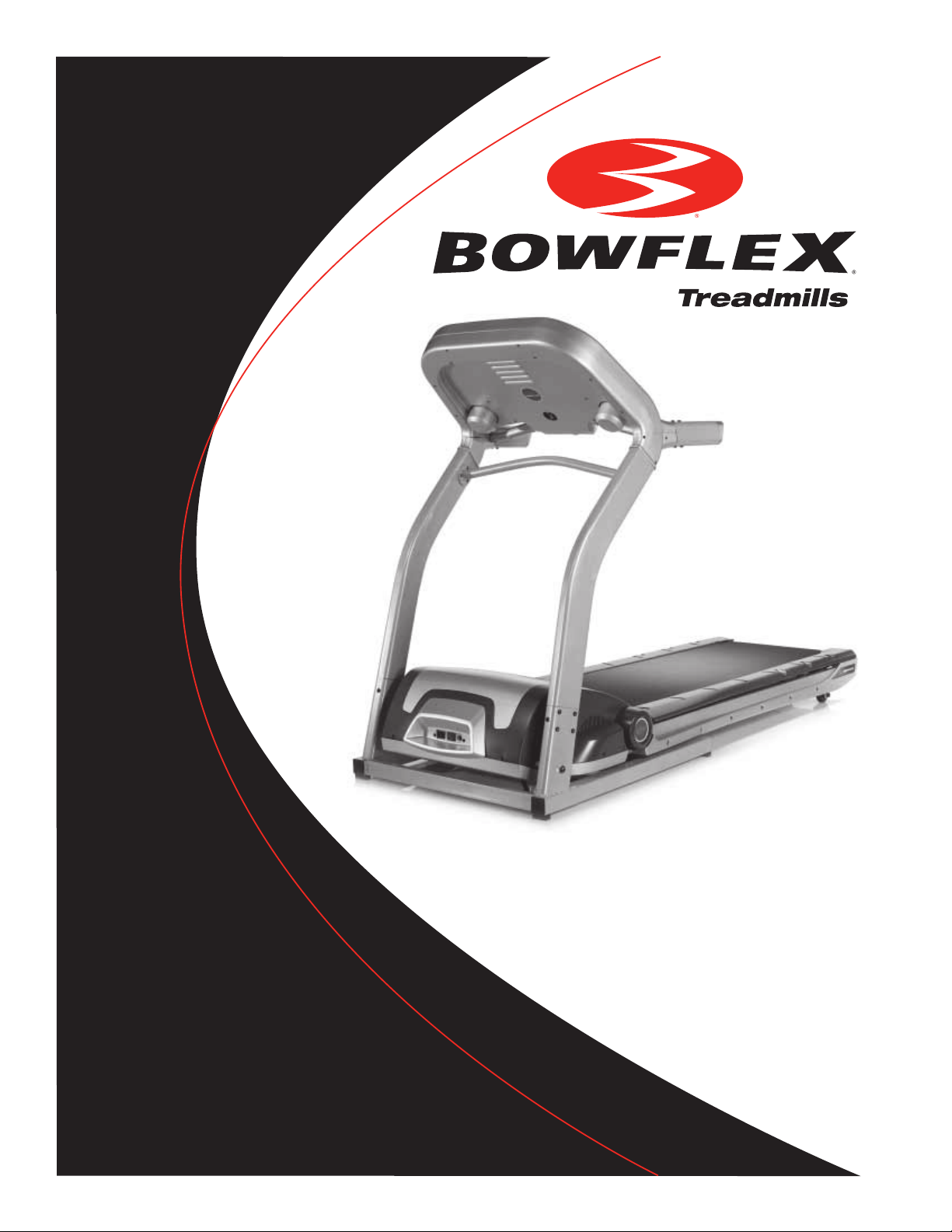
Bowflex
Assembly Manual
®
3, 5 & 7 Series
Treadmills
Page 2

Congratulations on your commitment to fitness and your purchase of the Bowflex® 3, 5 and 7 Series
treadmill. Before assembling your Bowflex® 3, 5, and 7 Series treadmill please read the Assembly
Manual and follow the Important Safety Precautions. For information on how to use your Bowflex® 3,
5, and 7 Series treadmill refer to the Bowflex® 3, 5, and 7 Series treadmill Owner’s Manual.
Nautilus, Inc.
16400 S.E. Nautilus Drive
Vancouver, Washington, USA 98683
1-800-NAUTILUS (1-800-628-8458)
Fax (800) 898-9410
Nautilus.com
Bowflex.com
Table of Contents
Important Safety Precautions . . . . . . . . . . . . . . . . . . . . . . . . . . . . . . . 1
Getting To Know Your Machine . . . . . . . . . . . . . . . . . . . . . . . . . . . . . . . 2
Parts and Hardware Lists . . . . . . . . . . . . . . . . . . . . . . . . . . . . . . . . . 4
Assembly Drawing with Reference Number . . . . . . . . . . . . . . . . . . . 7
Assembly Guide . . . . . . . . . . . . . . . . . . . . . . . . . . . . . . . . . . . . . . . . . . 9
Folding, Transporting & Unfolding Your Treadmill . . . . . . . . . . . . . . 14
Important Contact Numbers . . . . . . . . . . . . . . . . . . . . . . . . . . . . . . . 17
Page 3
Important Safety Precautions
Before starting any exercise program, consult with your physician or health professional. He or she can help establish the correct
exercise frequency, intensity (target heart rate zone) and time appropriate for your particular age and condition.
The following 3 warnings listed below are also located on the handlebar of the treadmill. Failure to follow any of these safeguards
may result in injury or serious health problems.
• Read and understand the Owner’s Manual and operation instructions prior to use. If you do not have an Owner’s Manual, call 1-
800-628-8458
• If you feel any unusual pain or tightness in your chest, shortness of breath or dizziness, feel faint or have any discomfort while you
exercise, STOP! Consult your physician.
• Keep children and pets off the treadmill.
(USA),
1-800-636-8316
(French Canadian) or
READ ALL INSTRUCTIONS BEFORE
ASSEMBLING THE MACHINE.
+41-26-460-77-77
(International) to obtain one.
Recycling
Do not dispose of this product as refuse. This product is to be recycled. For information on the proper method
of disposal contact a Nautilus Customer Service Representative. Contact information is available in the
Important Contact Numbers section in this manual.
Fitness Safeguards and Warnings
1
Page 4
&53%$
Getting To Know Your Machine
Power Cord Information
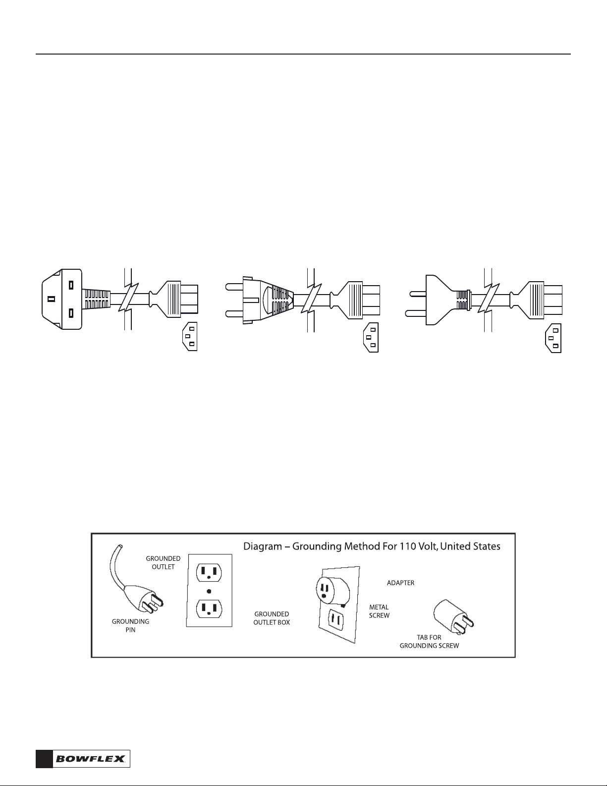
Nautilus, Inc. sells its products in many different countries some of which have different power cord and power outlet configurations.
For locations where the furnished cord(s) are not suitable, contact your local dealer or service provider to find where a local high
quality power cord meeting the following technical requirements is available. Do not attempt to use the treadmill without the proper
power cord appropriate for your country and location.
Plug the power cord of the treadmill directly into a dedicated grounded circuit carrying 15 amps (110 Volt model) or 7 amps (220
Volt model) . We recommend the use of a surge protector. Position the treadmill so that the wall plug is visible and accessible. If the
Bowflex® Treadmill power cord is damaged, it must be replaced with a new power cord from Nautilus, Inc. Please contact your
local dealer or Nautilus, Inc. directly.
DepenDing upon your region you will have one of the following power corDs.
Part : Power Cord (British)
Qty: 1
P/N: HH2132
Part : Power Cord (European)
Qty: 1
P/N: HH
2133
Part : Power Cord (Australian)
Qty: 1
P/N: HH
2135
Grounding Instructions
This product must be grounded. If it should malfunction or break down, grounding provides a path of least resistance for electric
current, reducing the risk of electric shock. The power cord is equipped with an equipment-grounding conductor and a grounding
plug. The plug must be plugged into an appropriate outlet that is properly installed and grounded in accordance with all local codes
and ordinances.
• Position the treadmill on a clear, level surface. Do not place the treadmill on thick carpet as it may interfere with proper
ventilation. Treadmill mats can usually be purchased from your treadmill dealer.
2
Fitness Safeguards and Warnings
Page 5

Basic Assembly Principles
Here are few basic assembly tips that can make assembly of your Bowflex
1. You can make the assembly process go faster by gathering the pieces you need for each step prior to starting the step.
2. As a general rule, and for all fasteners on your Bowflex
towards the left will loosen. An easy way to remember this is by remembering the expression, “Lefty loosey, righty tighty.”
3. The Allen wrenches and Phillips screwdriver tools needed to assemble your Bowflex
may find the use of a utility knife or scissors beneficial during the unpacking process.
4. It is recommended that you use two people to assemble your Bowflex
® 3, 5, and 7 Series treadmill, turning toward the right will tighten, turning
® 3, 5, and 7 Series treadmill quick and easy.
® 3, 5, and 7 Series treadmill
® 3, 5, and 7 Series treadmill
.
are provided.
You
Select Your Workout Area
Select where you are going to put your
level surface. You will need at least 20 inches (.5 meters) on each side of the treadmill and 79 inches (2 meters) behind your treadmill for
dismount.
Make sure that the location you choose has a grounded, 3-prong power outlet within reach of the treadmill power cord, and you have
the appropriate power cord for the outlet.
Bowflex
® 3, 5, and 7 Series treadmill carefully. The best place for your treadmill is on a hard,
NOTE: The Bowflex
or circuit breaker is GFI, look for a test and reset button on them. If they have the test and reset button it is a GFI outlet or
circuit breaker.
Further, if you ever perform any repairs on your treadmill that require you to lay it on its side, you will need at least five feet to one side
of your workout area.
® 3, 5, and 7 Series treadmill
is designed to plug into a grounded, non-GFI outlets only. To determine if your outlet
Fitness Safeguards and Warnings
3
Page 6

Parts and Hardware Lists
Bowflex® 3, 5, and 7 Series Treadmills' Parts List, Treadmill Hardware List,
and Assembly Instructions
Assembly of the Bowflex® 3, 5, or 7 Series Treadmill is divided into 5 easy stages; each comprised of only a few setup steps. Before
proceeding with the assembly, please read over the easy to follow instructions to familiarize yourself with the process. You will
need the following:
• Flat area of 4’ x 8’ to assemble and properly use the Bowflex® 3, 5, or 7 Series Treadmill.
• Two people to assemble the treadmill.
• 5 mm Allen wrench (supplied)
• Phillips head screw driver (supplied)
• Silicon Lube (supplied)
Also, to ensure quick and easy set up of the Bowflex® 3, 5, or 7 Series Treadmill, please verify the size and quantity of each of the
enclosed assembly hardware. Included are parts lists and images of the hardware.
4
Parts and Hardware Lists
Page 7

Parts List
Check Quantity Description Reference #
1 Frame A
1 Handrail (L) B
1 Handrail (R) C
1 Computer Console D
1 Left Upright E
1 Right Upright F
1 Inner Handrail Cover (L) G
1 Outer Handrail Cover (L) H
1 Inner Handrail Cover (R) I
1 Outer Handrail Cover (R) J
1 Cross Bar K
Exploded View
Parts and Hardware Lists
5
Page 8

Hardware List
Check Quantity Description Reference #
22 Allen Screw M8 x P1.25 x 15 a
6 Phillips Head Screw M8 x P1.0 x 15 b
6 Allen Screw M8 x P1.25 x 15 c
6 Phillips Head Screw 4 x 16 d
1 Allen Wrench 5mm/Screwdriver e
1 Allen Wrench 6mm f
1 Safety Key/Clip g
1 Silicon Lube h
1 *Power Cord (attached on 3.1 model) i
Note: Please verify you have all correct parts and quantities before assembling the unit.
If you are missing items, are short quantities, or have damaged components, please contact Nautilus, Inc.
at 1-800-864-1270 (USA), 1-800-636-8316 (French Canadian) or +41-26-460-77-77 (International).
6
Parts and Hardware Lists
Page 9
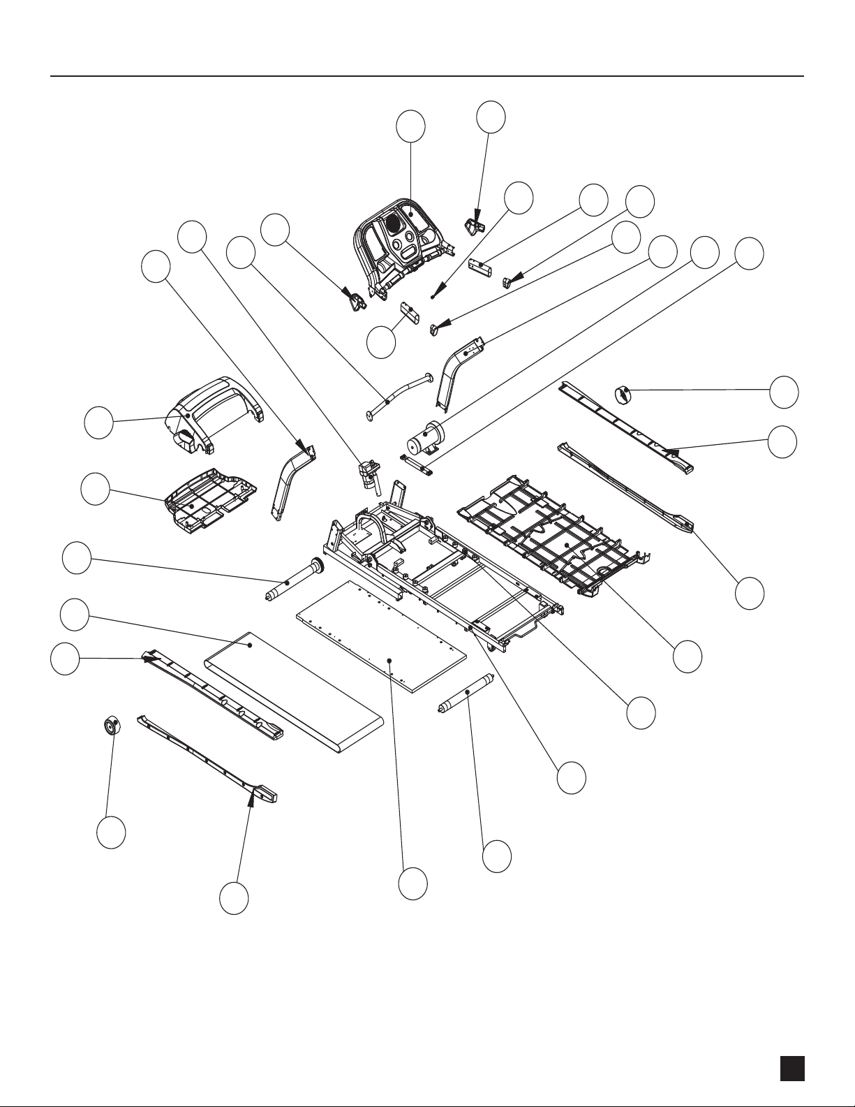
Assembly Drawing with Reference Numbers
Parts and Hardware Lists
7
Page 10

Parts List
Reference # QTY Description
1 1 Console
2 1 Hand Rail Cover set / Right
3 1 Emergency Stop Magnet
4 2 Hand Rail
5 2 Hand Rail End Cap
6 1 Right Upright Assembly
7 1 Motor
8 1 Soft Drop™ Cylinders
9 1 Right Roller Cover
10 1 Right Side Rail
11 1 Right Bottom Side Rail
12 1 Deck Bottom Plastic Cover
13 8 Rubber Isolator
14 1 Frame Assembly
15 1 Rear Roller
16 1 Deck
17 1 Left Bottom Side Rail
18 1 Left Roller Cover
19 1 Left Side Rail
20 1 Walking Belt
21 1 Front Roller
22 1 Motor Pan
23 1 Motor Cover
24 1 Left Upright Assembly
25 1 Incline Motor
26 1 Upright Crossbar Assembly
27 1 Hand Rail Cover Set / Left
8
Parts and Hardware Lists
Page 11

Assembly Instructions
Left Upright
Allen Screws
Allen Screws
Frame
Right Upright
Wire Connector
Control Wire
To ensure ease of assembly please verify the size and quantity of all the required
assembly hardware and parts with the enclosed parts list and hardware chart.
The assembly process has been broken down into 5 easy-to-follow steps. Please
take just a few moments to read over these instructions to familiarize yourself with
the process to make assembly quick and trouble-free.
Assembly Step #1 Attach Uprights to Main Unit
1. Tie the attached black guide wire to the wire connector and feed the wire slowly through the bot tom Left Upright.
2. Insert Left Upright, and Right Upright into the Frame. Be sure not to pinch the control wire when inserting Left Upright. Use
Assembly hardware required: (12) M8 x P
Allen Screws to secure in position. Do not fully tighten Allen Screws - leave loose for adjustment.
1.25
x 15 Allen Screws (item a)
Note: For safety have one person hold the upright while securing them to the main unit.
Assembly Instructions
9
Page 12

Assembly Step #2 Attach Cross Bar to Uprights
#ROSSBAR
0HILLIPSHEAD
3CREWS
Assembly hardware required: (6) M8 x P
1. Attach Crossbar bet ween the Lef t and Right Uprights using Phillips-head screws. Do not fully tighten screws - leave loose for
adjustment.
1.0
x 15 Phillips-head Screws (item b)
10
Assembly Instructions
Page 13

Assembly Step #3 Attach Console to Uprights
Console
Upper Control wire
Allen Screws
Left Upright
Lower Control
Wire
Right Upright
Allen Screws
Console Flanges
THIS STEP REQUIRES TWO PEOPLE. THE
CONSOLE IS AWKWARD AND HEAVY. IT IS
POSSIBLE TO PINCH YOUR FINGERS WHEN
Assembly Hardware Required : (6) M8 x P1.25 x 15 Allen Screws (item c)
1. With one person holding the Console in place, have the second person connect the Upper Control Wire (attached to the
Console) to the Lower Control Wire (on the Lef t Upright).
CONNECTING IT TO THE UPRIGHTS.
2. Once the Control Wire has been connected, tuck the excess wire into the Upright. Inser t the Console Flanges into the Left and
Right Uprights and secure with Allen screws.
3. Before proceeding to the nex t step tighten all the Allen Screws on the Uprights and Phillips Head Screws on the Crossbar.
Note: Be sure not to pinch the control wire when securing the Console to the Upright.
Assembly Instructions
11
Page 14

Assembly Step #4 Attach Handrail Covers
Right Outer
Handrail
Cover
Right Inner
Handrail
Cover
Pillips-head Screws
Left Outer
Handrail
Cover
Left Inner
Handrail
Cover
12
Assembly Hardware Required : (6) 4 x 16 Phillips-head Screws, 3 per side (item d).
1. Attach Inner and Outer Handrail Covers using Phillips-head screws.
Assembly Instructions
Page 15

Assembly Step #5 Attach Handrails
Left Handrail
Right Handrail
Allen Screws
Assembly Hardware Required : (8) M8 x P1.25 x 15 Allen Screws, 4 per side (item a).
1. Attach Handrails to the sides of Console, aligning the holes and securing with Allen Screws.
Assembly Instructions
13
Page 16

Folding, Transporting & Unfolding Your Treadmill
This treadmill has a folding mechanism; you must stop operation while folding and transporting. Make sure the power is off and the
power cord is removed and unplugged before folding and transporting the treadmill.
Note: After initial assembly your Bowflex Treadmill must be calibrated before it can be folded.
Please follow calibration instructions in your Owner's Manual.
To Fold the Treadmill:
1. Stop the Treadmill belt.
2. Bring Elevation to zero.
3. Turn off power.
4. Squeeze the release mechanism then lift the deck to fold up the treadmill. Make sure the pin clicks into position and the deck is
secure before moving the treadmill.
14
Folding, Transporting & Unfolding Your Treadmill
Page 17

To Transport the Treadmill:
1. After folding, as mentioned in the To Fold the Treadmill section, please be sure deck is locked and engaged in the up
position. If treadmill will not lock in up position, check to see that elevation is at zero.
2. Unplug the Power Cord.
3. Pull backwards, holding the top of the deck, until the wheels can move smoothly.
Folding, Transporting & Unfolding Your Treadmill
15
Page 18

To Unfold the Treadmill:
Squeeze the release mechanism and slowly lower the deck until it sits on level ground. The SoftDrop™ feature lets the deck drop
gently and safely under it’s own weight.
That’s it!
You’re finished and now you can begin to reach your fitness goals!
Please reference the Owner’s Manual for information regarding computer operation,
product maintenance and Warranty information.
16
Folding, Transporting & Unfolding Your Treadmill
Page 19

Important Contact Numbers
If you need assistance, please have both the serial number of your machine and the date of purchase available when you contact the
appropriate Nautilus, Inc. office listed below.
OFFICES IN THE UNITED STATES:
E-mail: customerservice@nautilus.com
• NAUTILUS INNOVATION CENTER
Nautilus, Inc.
1886 Prairie Way
Louisville, Colorado, USA 80027
Vancouver, Washington, USA 98683
Phone: 800-NAUTILUS (800-628-8458)
Email: customerservice@nautilus.com
Fax: 800-898-9410
• TECHNICAL/CUSTOMER SERVICE
Nautilus, Inc.
World Headquarters
16400 SE Nautilus Drive
Vancouver, Washington, USA 98683
Phone: 800-NAUTILUS (800-628-8458)
Email: customerservice@nautilus.com
Fax: 877-686-6466
• CORPORATE HEADQUARTERS
Nautilus, Inc.
World Headquarters
16400 SE Nautilus Drive
Vancouver, Washington, USA 98683
Phone: 800-NAUTILUS (800-628-8458)
INTERNATIONAL OFFICES:
For technical assistance and a list of distributors in your area, please
call or fax one of the following numbers.
• INTERNATIONAL CUSTOMER SERVICE
Nautilus International S.A.
Rue Jean Prouvé 6
1762 Givisiez / Switzerland
Tel: + 41-26-460-77-77
Fax: + 41-26-460-77-70
Email: technics@nautilus.com
BUSINESS OFFICES:
• SwITzERLAND OffICE
Nautilus Switzerland S.A.
Tel: + 41-26-460-77-66
Fax: + 41-26-460-77-60
• GERMANY and AUSTRIA OffICE
Nautilus GmbH
Tel: +49-2203-20-20-0
Fax: +49-2203-20-20-4545
• ITALY OffICE
Nautilus Italy s.r.l.
Tel: +39-051-664-6201
Fax: +39-051-664-7461
• UNITED KINGDOM OffICE
Nautilus UK Ltd.
Tel: +44-1908-267-345
Fax: +44-1908-267-346
• CHINA OffICE
Nautilus Representative Office
Tel: +86-21-523-707-00
Fax: +86-21-523-707-09
Folding, Transporting & Unfolding Your Treadmill
17
Page 20

©
2007
Nautilus, Inc. All Rights Reserved. Nautilus, Inc. World Headquarters,
1-800
-NAUTILUS (1-
All other trademarks are trademarks of their respective companies.
Printed in China.
800-628-8458
) Bowflex, SoftDrop, and the Bowflex logo are either registered trademarks or trademarks of Nautilus, Inc.
16400
S.E. Nautilus Drive, Vancouver, Washington USA
98683
 Loading...