

Boston Acoustics MCS 150 Owner's Manual
OWNER’S MANUAL / SAFETY INSTRUCTIONS / COMPLIANCE INFORMATION
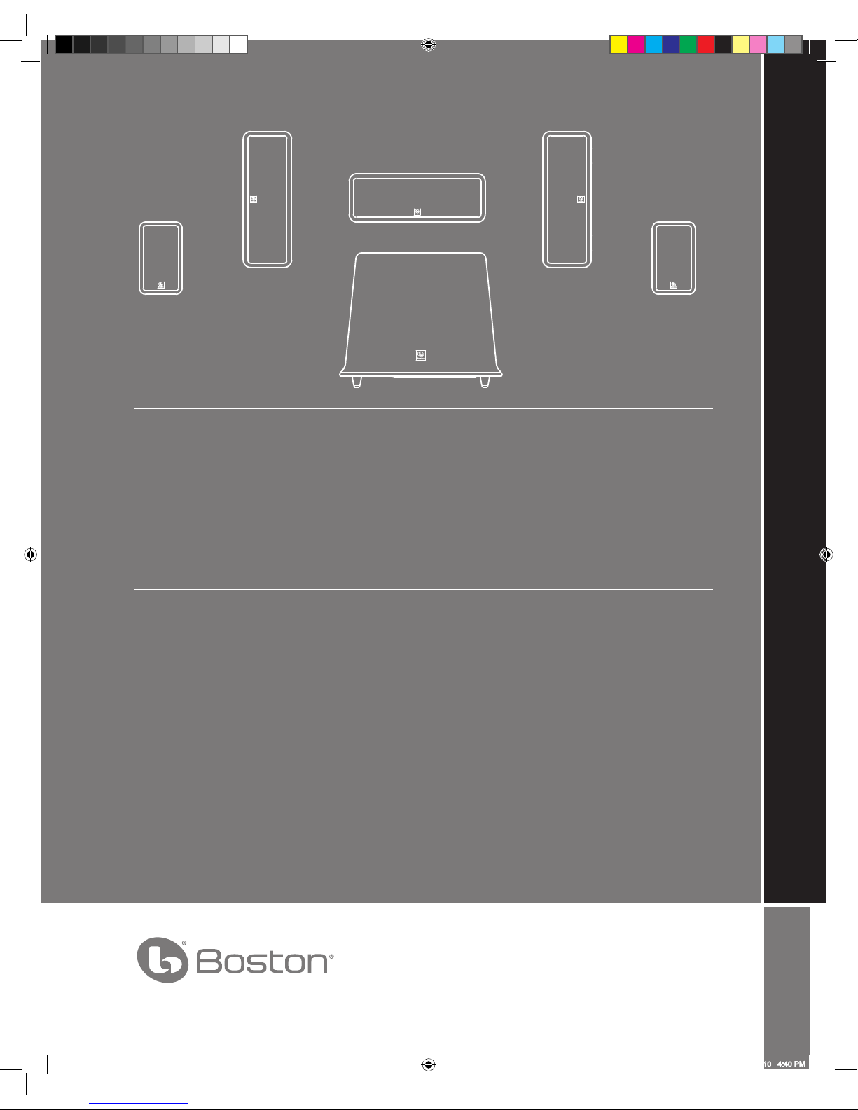
MCS 150
5.1 Surround Speaker System
Español
MCS 150
Sistema de Altavoces
Surround 5.1
Français
MCS 150
Système de haut-parleurs
multimédia 5.1
142-003871-0_MCS_150_Manual.indd 1 8/31/10 4:40 PM
IMPORTANT SAFETY INSTRUCTIONS
This symbol found on the apparatus indicates hazards
arising from dangerous voltages.
This symbol found on the apparatus indicates the user
should read all safety statements found in the user
manual.
This symbol found on the apparatus indicates double
insulation.
WARNING! To reduce the risk of fire or electrical shock,
do not expose this apparatus to rain or moisture
.
This symbol found on the apparatus indicates that
the apparatus must be placed in a separate collection
facility for electronic waste and not disposed with
household waste.
1. Read these instructions.
2. Keep these instructions.
3. Heed all warnings.
4. Follow all instructions.
5. Do not use this apparatus near water.
6. Clean only with dry cloth.
7. Do not block any ventilation openings. Install in accordance
with the manufacturer’s instructions.
8. Do not install near any heat sources such as radiators, heat
registers, stoves, or other apparatus (including amplifiers)
that produce heat.
9. Do not defeat the safety purpose of the polarized or
grounding type plug. A polarized plug has two blades with
one wider than the other. A grounding-type plug has two
blades and a third grounding prong. The wide blade or
the third prong is provided for your safety. If the provided
plug does not fit into your outlet, consult an electrician for
replacement of the obsolete outlet.
10. Protect the power cord from being walked on or pinched
particularly at plugs, convenience receptacles, and the point
where they exit from the apparatus.
11. Only use attachments/accessories specified by the manufacturer.
12. Unplug this apparatus during lightning storms or when
unused for long periods of time.
13. Refer all servicing to qualified service personnel. Servicing
is required when the apparatus has been damaged in any
way, such as power-supply cord or plug is damaged, liquid
has been spilled or objects have fallen into the apparatus,
the apparatus has been exposed to rain or moisture, does
not operate normally, or has been dropped.
14. Maintain a minimum distance of 2” (50mm) around the
front, rear, and sides of the apparatus for sufficient ventilation. The ventilation should not be impeded by covering the
ventilation openings or placing on or around the apparatus
items such as newspapers, table-cloths, curtains, etc.
15. No open flame sources, such as lighted candles, should be
placed on the apparatus.
16. The apparatus shall not be exposed to dripping or splashing. No objects filled with liquids, such as vases, shall be
placed on the apparatus.
17. Either the power inlet connector on the rear of the apparatus or the power plug at the wall must remain accessible, to
be able to disconnect power from the apparatus.
18. To completely disconnect this apparatus from the AC Mains,
disconnect the power supply cord plug from the AC receptacle.
19. The mains plug of the power supply cord shall remain readily operable.
American Users:
Note: This equipment has been tested and found to comply with
the limits for a Class B digital device, pursuant to part 15 of the
FCC Rules. These limits are designed to provide reasonable protection against harmful interference in a residential installation.
This equipment generates, uses, and can radiate radio frequency
energy and, if not installed and used in accordance with the
instructions, may cause harmful interference to radio communications. However, there is no guarantee that interference will
not occur in a particular installation. If this equipment does cause
harmful interference to radio or television reception, which can
be determined by turning the equipment off and on, the user is
encouraged to try to correct the interference by one or more of
the following measures:
• Reorient or relocate the receiving antenna.
• Increase the separation between the equipment and
receiver.
• Connect the equipment into an outlet on a circuit different from that to which the receiver is connected.
• Consult the dealer or an experienced radio/TV technician
for help.
Canadian Users
This class B digital apparatus complies with Canadian ICES-003.
Cet appareil numérique de classe B est conforme á la norme
NMB-003 du Canada.
142-003871-0_MCS_150_Manual.indd 2 8/31/10 4:40 PM
3
MCS 150 Introduction
Thank you for purchasing a Boston Acoustics Multi-Channel Speaker System. These speakers incorporate high-quality
components that produce the famous Boston sound. The MCS 150 is ideally suited for use as a 5.1 channel solution in a
high-quality home theater or music system. The MCS 150 is complete with everything you need for the typical speaker
system, surround speakers, LCR (left, center and right), and a subwoofer. Please check out Bostonacoustics.com\placement
for information on placing your speakers.
The MCS 150 speaker system delivers exceptionally articulate on-screen dialog, music, effects, and room filling bass from
a small, sleek package. Compact driver placement and quality, system-specific crossovers assure a wide uniform dispersion
for complete coverage of a listening room. All speakers also feature MagnaGuard® magnetic shielding which ensures the
speaker’s magnetic field does not interfere with the televisions picture.
Specifications LCR Speakers Surround Speakers Powered Subwoofer
Frequency Response: 110Hz – 20kHz 120Hz – 20kHz 40 - 150Hz
Recommended Amplier 10 – 150 watts 10 – 150 watts —
Power Range:
Sensitivity: 88dB [2.8v at 1m] 88dB [2.8v at 1m] —
Nominal Impedance: 8 ohms 8 ohms —
Crossover Frequency: 2,700Hz 3,000Hz
Amplier Output: — — 200 watts RMS; BassTrac®
circuitry eliminates distortion
Woofer: — — 10” (254mm) DCD
Midrange: Dual 3½” (89mm) 3” (75mm) —
copolymer DCD with copolymer DCD with
Phase Plugs and Phase Plugs and
MagnaGuard® MagnaGuard
Tweeter:
1” (25mm) Kortec® Soft Dome ¾” (19mm) Kortec Soft Dome
—
Dimensions: (H x W x D) 137⁄8 x 5 x 41⁄16” 73⁄8 x 43⁄8 x 311⁄16” 13¾ x 16½ x 16½”
(352 x 127 x 103mm) (189 x 113 x 93mm) (349 x 419 x 419mm)
Weight: 5.5 lbs 2.5 lbs 31.25 lbs
(2.27kg) (1.14kg) (14.15kg)
.
142-003871-0_MCS_150_Manual.indd 3 8/31/10 4:40 PM
4
Unpacking the System
Carefully unpack the system. If there is any sign of damage from transit, report it immediately to your dealer and/or delivery
service. Keep the shipping carton and packing materials for future use.
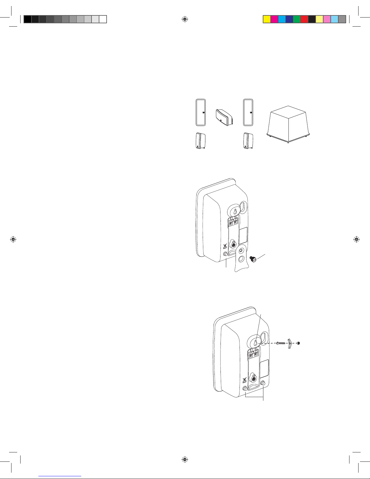
Open the package and verify the following contents:
(3) LCR (left, center, right) speakers
(2) Surround speakers
(1) Subwoofer
(2) Feet (for use with LCR speaker’s horizontal use)
(2) Thumb screws
(4) Rubber bumpers (used for wall mounting)
Placement Options
The MCS 150 LCR and surround speakers are easily placed on a
tabletop or wall-mounted. The speakers are configured for tabletop
use when you first unpack the system. Two LCR speakers will have
one foot installed that will keep your speaker level when used
in the vertical position. The other LCR speaker will have 2 feet
installed for horizontal use as the center speaker. There are 2
sets of holes on each foot; by using the upper of the two holes,
the speakers will have a slight forward angle for use on a high
shelf. When the feet on the back of your speakers are removed,
the speakers are easy to wall-mount.
The MCS 150 LCR and surround speakers are designed to
easily mount on the wall using the keyhole slot(s) on the back
of the speaker. When mounting the speakers to the wall, use
the supplied rubber bumpers. You must remove the attached
foot to wall-mount your speakers. Remove the thumbscrew
from the back of the foot. It is slotted for easy removal with a
screwdriver or a coin.
The keyhole mounting option is similar to hanging a picture frame
on a wall. Install a #8 screw (not included) into the sheetrock,
making sure to go into a stud, and hang the speaker onto the screw head.
If a stud is not available, a sheetrock anchor should be used to support the
weight of the speaker. It is advisable to connect the speaker wire prior to
wall-mounting.
NOTE: Because there are so many different kinds of surfaces on
which the speakers could be mounted. There is no one type of
fastener that we could supply that would work in all the possible
situations. So taking into account the surface the speaker is being
mounted on, acquire the appropriate type of fasteners. If you’re not
sure what type of fastener to use, take the mounting bracket to a
friendly hardware store, tell them about the wall you’re mounting the
speaker on, and ask them to recommend an appropriate fastener.
Keep in mind the weight of the speaker.
(3) LCR Speakers
with Removable Feet
(2) Surround Speakers
with Removable Feet
Subwoofer
Rubber
Bumper
Use the lower screw hole
for normal speaker position;
use the upper screw hole to
tilt the speaker forward.
Keyhole Mount
Rubber Bumpers
142-003871-0_MCS_150_Manual.indd 4 8/31/10 4:40 PM
5
Speaker Wires
For short runs of less then 20 feet or so you can use 18 gauge wire. For runs of more than 50 feet use 16 gauge wire.
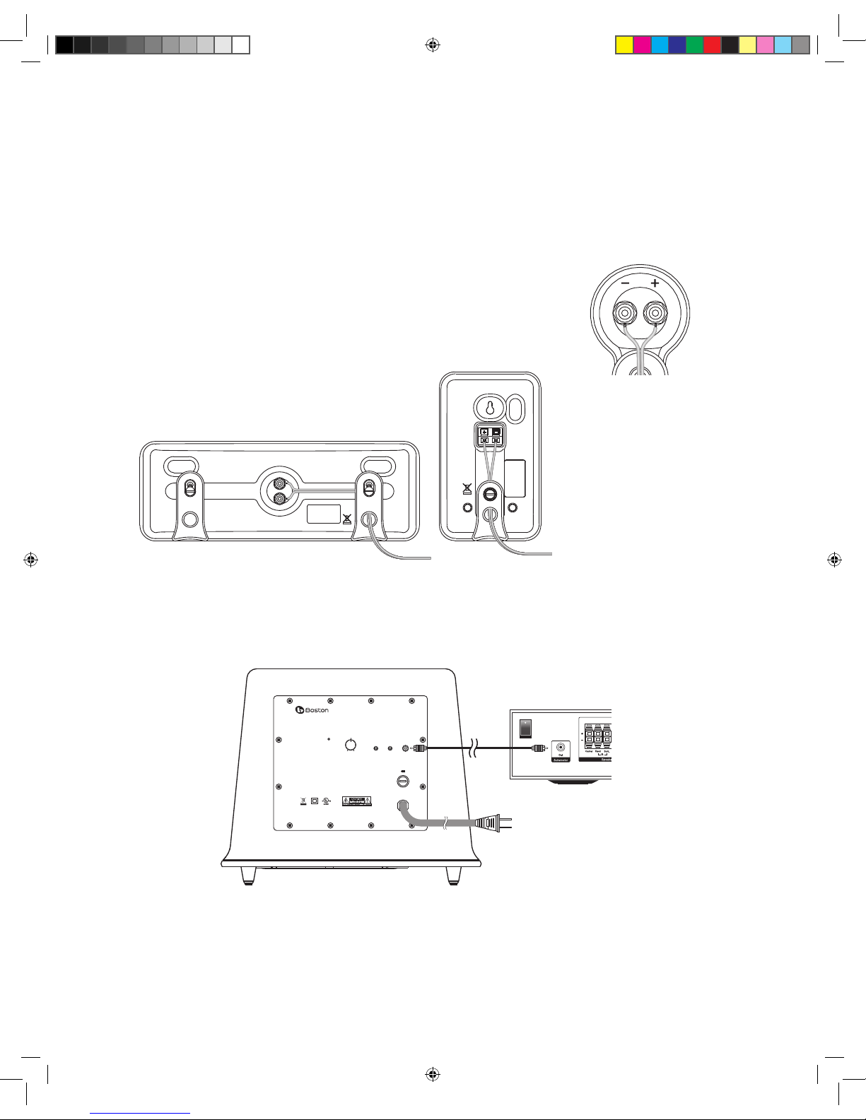
Speaker Connections
After your speakers are properly placed, you are ready to wire your system. First, turn off all system power. Please see
the illustration below for guidance connecting the wires to the MCS 150 satellites and center channel. For connection
to your receiver please refer to its owner’s manual.
Important!
To ensure the best performance
observe polarities when making speaker connections, as shown
in the illustration. Connect each + terminal on the back of the amplifier or receiver to the
respective + (red) terminal on each speaker. Connect the – (black) terminals in the same way.
If the connections are not made correctly it can
cause poor bass response and imaging. Also,
to avoid short circuits that may damage your equipment be careful not to let any of the bare
wires touch each other.
Subwoofer Connections
Turn off all power. Use a subwoofer cable, as shown, to connect your digital receiver’s LFE subwoofer output to the subwoofer.
Connect the other end to the “Line In” on the back of the Subwoofer.
Speaker wires can be routed through
the channels on the back of the
speaker and the holes in the feet.
Be sure to maintain proper +
and – polarity at all speaker
wire connections.
VOLUME
LINE IN
ON
AUTO
OFF
POLARITY
180
º
0
º
MIN MAX
AUDIO/VIDEO
APPARATUS
86AC
T2.5A/250V
120V~
60Hz
300W
MCS 150
This device complies with Part 15 of the FCC Rules. Operation is subject to the following two conditions:
(1) this device may not cause harmful interference, and
(2) this device must accept any interference received, including interference that may cause undesired operation.
This Class B digital apparatus complies with Canadian ICES-003.
Cet appareil numérique de la classe B est conforme à la norme NMB-003 du Canada.
.
142-003871-0_MCS_150_Manual.indd 5 8/31/10 4:40 PM
6
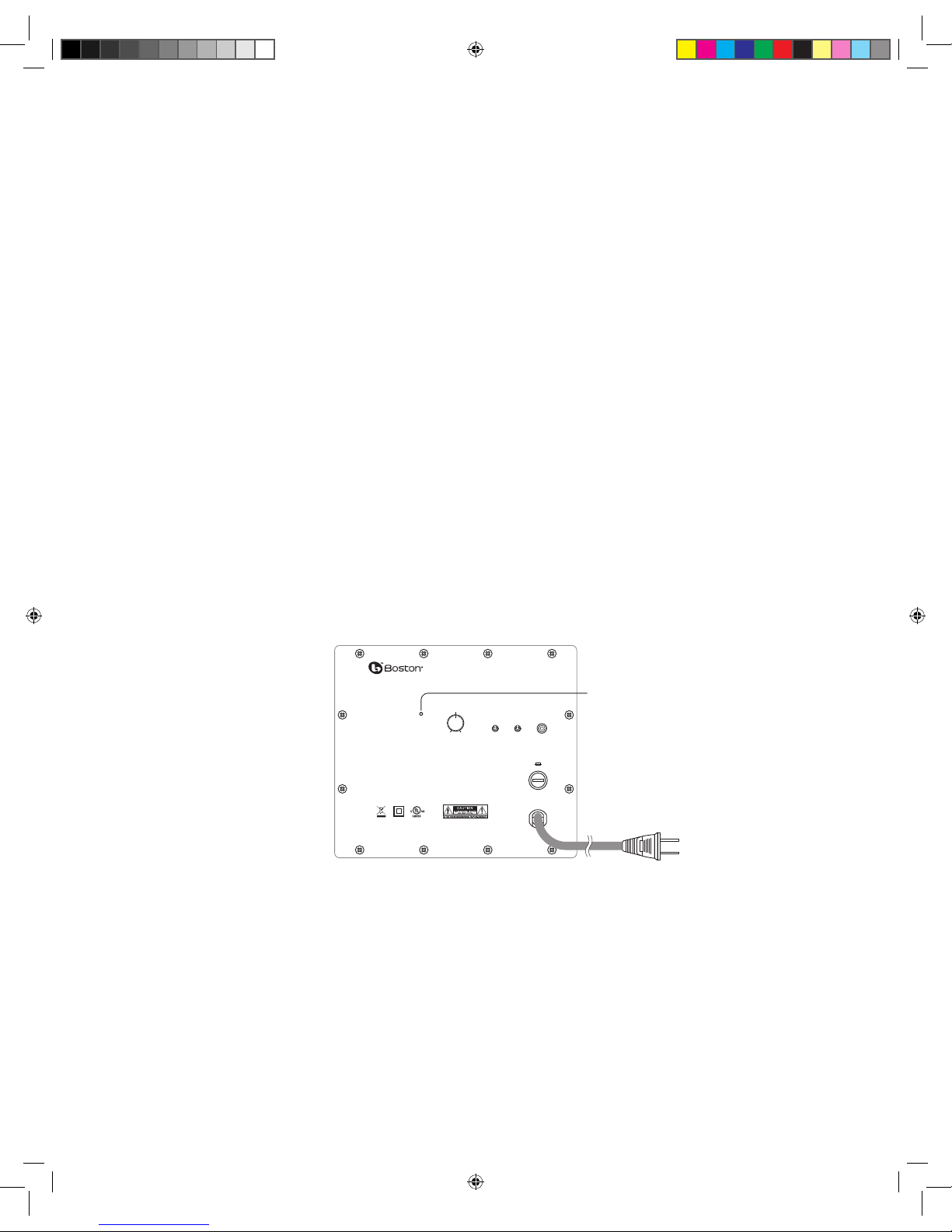
Subwoofer Controls
Power On/Auto/Standby
Plug the subwoofer AC cord into a wall outlet. We do not recommend using the outlets on the back of the receiver. Set the
power switch to the desired setting.
OFF – The subwoofer is off and will not produce any sound. You may want to turn your subwoofer off if you will not be
using it for some time or wish to conserve electricity.
AUTO – The subwoofer will power on whenever a signal is detected. If no signal is detected after several minutes, it will
automatically enter the Standby mode.
ON – The subwoofer is always on.
An LED indicator next to the volume control indicates what mode the subwoofer is in.
OFF = The subwoofer is off
RED = STANDBY (No signal detected, Amp Off )
GREEN = ON (Signal detected, Amp On)
The subwoofer will automatically enter the Standby mode after several minutes when no signal is detected from your system.
The subwoofer will then power ON instantly when a signal is detected.
Volume Control
Begin by adjusting the Subwoofer Volume Control to the 11 o’clock position. Further adjust the Subwoofer Volume Control
until you hear a match in volume between the main speakers and subwoofer. Ideally, bass response should not overpower
the room but rather be adjusted so there is a natural blend across the entire musical range.
Polarity Control
Selects regular (0°) or inverted (180°) polarity for the subwoofer. Set this switch to the position that provides the fullest, most
dynamic bass when auditioned from the primary seating position. The effect of polarity will be most audible on low-frequency
percussion instruments or music with a continuously repeating bass line, and may not produce a dramatic change at all.
Operation
When using the MCS 150 in a Dolby® Digital or DTS™ home theater system, make sure all speakers are set to “Small”. When
using the system in a Dolby Pro Logic® home theater system, make sure the receiver’s center channel mode is set to “Normal.”
Some receivers/processors offer different setup options for each source or surround mode (e.g., CD-stereo, videotape, Dolby
Digital, Dolby Pro Logic). In each case, follow your equipment’s instructions to ensure that the subwoofer output is turned on
and that the speakers are set to “Small” in each mode.
If your receiver has adjustable crossover settings, we recommend the subwoofer crossover be set at 120Hz.
Refer to the owner’s manual for your AV receiver for any additional recommendations on system operation.
VOLUME
LINE IN
ON
AUTO
OFF
POLARITY
180
º
0
º
MIN MAX
AUDIO/VIDEO
APPARATUS
86AC
T2.5A/250V
120V~
60Hz
300W
MCS 150
This device complies with Part 15 of the FCC Rules. Operation is subject to the following two conditions:
(1) this device may not cause harmful interference, and
(2) this device must accept any interference received, including interference that may cause undesired operation.
This Class B digital apparatus complies with Canadian ICES-003.
Cet appareil numérique de la classe B est conforme à la norme NMB-003 du Canada.
LED Indicator
142-003871-0_MCS_150_Manual.indd 6 8/31/10 4:40 PM
 Loading...