


Horizon MCS 130
5.1 Surround Speaker System
Español |
Italiano |
Deutsch |
Horizon MCS 130 |
Horizon MCS 130 |
MCS 130 |
Sistema de Altavoces |
Sistema surround 5.1 |
5.1 Surround |
Surround 5.1 |
|
Lautsprechersystem |
Français |
Svenska |
Horizon MCS 130 |
Horizon MCS 130 |
Système de haut-parleurs |
5.1 Surroundhögtalarsystem |
multimédia 5.1 |
|
INFORMATION COMPLIANCE / INSTRUCTIONS SAFETY / MANUAL OWNER’S
...own your it Make Product .P.O.P Boston A
IMPORTANT SAFETY INSTRUCTIONS
This symbol found on the apparatus indicates hazards arising from dangerous voltages.
This symbol found on the apparatus indicates the user should read all safety statements found in the user manual.
This symbol found on the apparatus indicates double insulation.
1.Read these instructions.
2.Keep these instructions.
3.Heed all warnings.
4.Follow all instructions.
5.Do not use this apparatus near water.
6.Clean only with dry cloth.
7.Do not block any ventilation openings. Install in accordance with the manufacturer’s instructions.
8.Do not install near any heat sources such as radiators, heat registers, stoves, or other apparatus (including amplifiers) that produce heat.
9.Do not defeat the safety purpose of the polarized or grounding type plug. A polarized plug has two blades with one wider than the other. A grounding-type plug has two blades and a third grounding prong. The wide blade or the third prong is provided for your safety. If the provided plug does not fit into your outlet, consult an electrician for replacement of the obsolete outlet.
10.Protect the power cord from being walked on or pinched particularly at plugs, convenience receptacles, and the point where they exit from the apparatus.
11.Only use attachments/accessories specified by the manufacturer.
12.Unplug this apparatus during lightning storms or when unused for long periods of time.
13.Refer all servicing to qualified service personnel. Servicing is required when the apparatus has been damaged in any way, such as power-supply cord or plug is damaged, liquid has been spilled or objects have fallen into the apparatus, the apparatus has been exposed to rain or moisture, does not operate normally, or has been dropped.
14.Maintain a minimum distance of 2” (50mm) around the front, rear, and sides of the apparatus for sufficient ventilation. The ventilation should not be impeded by covering the ventilation openings or placing on or around the apparatus items such as newspapers, table-cloths, curtains, etc.
15.No open flame sources, such as lighted candles, should be placed on the apparatus.
WARNING! To reduce the risk of fire or electrical shock, do not expose this apparatus to rain or moisture.
This symbol found on the apparatus indicates that the apparatus must be placed in a separate collection facility for electronic waste and not disposed with household waste.
16.The apparatus shall not be exposed to dripping or splashing. No objects filled with liquids, such as vases, shall be placed on the apparatus.
17.Either the power inlet connector on the rear of the apparatus or the power plug at the wall must remain accessible, to be able to disconnect power from the apparatus.
18.To completely disconnect this apparatus from the AC Mains, disconnect the power supply cord plug from the AC receptacle.
19.The mains plug of the power supply cord shall remain readily operable.
 American Users:
Note: This equipment has been tested and found to comply with the limits for a Class B digital device, pursuant to part 15 of the FCC Rules. These limits are designed to provide reasonable protection against harmful interference in a residential installation. This equipment generates, uses, and can radiate radio frequency energy and, if not installed and used in accordance with the instructions, may cause harmful interference to radio communications. However, there is no guarantee that interference will not occur in a particular installation. If this equipment does cause harmful interference to radio or television reception, which can be determined by turning the equipment off and on, the user is encouraged to try to correct the interference by one or more of the following measures:
•Reorient or relocate the receiving antenna.
•Increase the separation between the equipment and receiver.
•Connect the equipment into an outlet on a circuit different from that to which the receiver is connected.
•Consult the dealer or an experienced radio/TV technician for help.
Canadian Users
This class B digital apparatus complies with Canadian ICES-003. Cet appareil numérique de classe B est conforme á la norme NMB-003 du Canada.

Specifications
LCR Speakers |
Surround Speakers |
Powered Subwoofer |
Frequency Response: |
110Hz – 20kHz |
120Hz – 20kHz |
40 - 150Hz |
|
|
|
|
Recommended Amplifier |
10 – 150 watts |
10 – 150 watts |
— |
Power Range: |
|
|
|
|
|
|
|
Sensitivity: |
88dB [2.8v at 1m] |
88dB [2.8v at 1m] |
— |
|
|
|
|
Nominal Impedance: |
8 ohms |
8 ohms |
— |
|
|
|
|
Crossover Frequency: |
2,700Hz |
2,700Hz |
|
|
|
|
|
Amplifier Output: |
— |
— |
200 watts RMS; BassTrac® |
|
|
|
circuitry eliminates distortion |
|
|
|
|
Woofer: |
— |
— |
10” (254mm) DCD |
Midrange: |
Dual 31/2” (89mm) |
|
copolymer DCD with |
|
Phase Plugs and |
|
MagnaGuard® |
31/2” (89mm) |
— |
copolymer DCD with |
|
Phase Plugs and |
|
MagnaGuard |
|
Tweeter: |
1” (25mm) Kortec® Soft Dome |
1” (25mm) Kortec Soft Dome |
— |
|
|
|
|
Dimensions: (H x W x D) |
137⁄8 x 5 x 41⁄16” |
87⁄16 x 51⁄2 x 4” |
133⁄4 x 161⁄2 x 161⁄2” |
|
(352 x 127 x 103mm) |
(214 x 140 x 102mm) |
(349 x 419 x 419mm) |
|
|
|
|
Weight: |
5 lbs |
3 lbs |
311/4 lbs |
|
(2.27kg) |
(1.36kg) |
(14.15kg) |
|
|
|
|
. |
|
|
|
MCS 130 Introduction
Thank you for purchasing a Boston Acoustics Multi-Channel Speaker System. These speakers incorporate high-quality components that produce the famous Boston sound. The MCS 130 is ideally suited for use as a 5.1 channel solution in a high-quality home theater or music system. The MCS 130 is complete with everything you need for the typical speaker system including speaker wire, surround speakers, LCR (left, center and right), and a subwoofer. Please check out Bostonacoustics.com\placement for information on placing your speakers.
The MCS 130 speaker system delivers exceptionally articulate on-screen dialog, music, effects, and room filling bass from a small, sleek package. Compact driver placement and quality, system-specifi c crossovers assure a wide uniform dispersion for complete coverage of a listening room. All speakers also feature MagnaGuard® magnetic shielding which ensures the speaker’s magnetic fi eld does not interfere with the televisions picture.
3

Unpacking the System
Carefully unpack the system. If there is any sign of damage from transit, report it immediately to your dealer and/or delivery service. Keep the shipping carton and packing materials for future use.
Open the package and verify the following contents:
(3)LCR (left, center, right) speakers
(2)Surround speakers
(1)Subwoofer
(2)40’ (12m) speaker wires
(3)15’ (4.6m) speaker wires
(1)15’ (4.6m) subwoofer cable
(2)Feet (for use with LCR speaker’s horizontal use)
(2)Thumb screws
(4)Rubber bumpers (used for wall mounting)
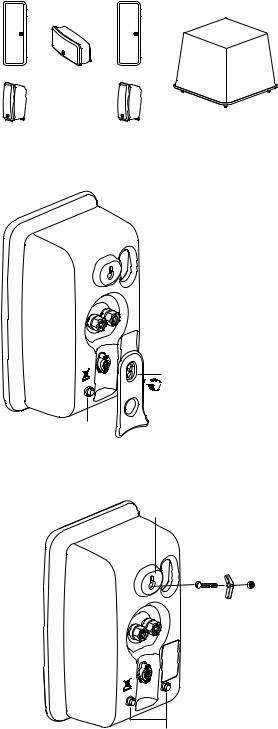
Placement Options
The MCS 130 LCR and surround speakers are easily placed on a tabletop or wall-mounted. The speakers are configured for tabletop use when you first unpack the system. Two LCR speakers will have one foot installed that will keep your speaker level when used in the vertical position. The other LCR speaker will have 2 feet installed for horizontal use as the center speaker. There are 2 sets of holes on each foot; by using the upper of the two holes, the speakers will have a slight forward angle for use on a high shelf. When the feet on the back of your speakers are removed, the speakers are easy to wall-mount.
The MCS 130 LCR and surround speakers are designed to easily mount on the wall using the keyhole slot(s) on the back of the speaker. When mounting the speakers to the wall, use the supplied rubber bumpers. You must remove the attached foot to wall-mount your speakers. Remove the thumbscrew from the back of the foot. It is slotted for easy removal with a screwdriver or a coin.
(3) LCR Speakers  with Removable Feet
(2) Surround Speakers
with Removable Feet
Rubber
Bumper
Subwoofer
Use the lower screw hole 


 for normal speaker position; use the upper screw hole to tilt the speaker forward.
The keyhole mounting option is similar to hanging a picture frame on a wall. Install a #8 screw (not included) into the sheetrock, making sure to go into a stud, and hang the speaker onto the screw head. If a stud is not available, a sheetrock anchor should be used to support the weight of the speaker. It is advisable to connect the speaker wire prior to wall-mounting.
NOTE: Because there are so many different kinds of surfaces on which the speakers could be mounted. There is no one type of fastener that we could supply that would work in all the possible situations. So taking into account the surface the speaker is being mounted on, acquire the appropriate type of fasteners. If you’re not sure what type of fastener to use, take the mounting bracket to a friendly hardware store, tell them about the wall you’re mounting the speaker on, and ask them to recommend an appropriate fastener. Keep in mind the weight of the speaker.
Keyhole Mount
Rubber Bumpers
4

Speaker Connections
After your speakers are properly placed, you are ready to wire your system. First, turn off all system power. Use the speaker wire include with the system to make your connections. Please see the illustration below for guidance connecting the wires to the MCS 130 satellites and center channel.
For connection to your receiver please refer to its owner’s manual.
Important!
To ensure the best performance observe polarities when making speaker connections, as shown in the illustration. Connect each + terminal on the back of the amplifi er or receiver to the respective + (red) terminal on each speaker. Connect the – (black) terminals in the same way.
If the connections are not made correctly it can cause poor bass response and imaging. Also, to avoid short circuits that may damage your equipment be careful not to let any of the bare wires touch each other.
.
Be sure to maintain proper + and – polarity at all speaker wire connections.
Speaker wires can be routed through the channels on the back of the speaker and the holes in the feet.
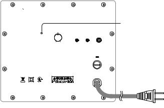
Subwoofer Connections
Turn off all power. Use the subwoofer cable included with your system to connect the subwoofer to your receiver’s Subwoofer or LFE output. Connect the other end to the “Line In” on the back of the Subwoofer.


 .$4
.$4
70-6.& |
|
|
|
|
|
|
|
10-"3*5: |
-*/& */ |
|
|
0/ |
|
|
|
|
"650 |
|
|
.*/ |
."9 |
0'' |
|
|
5 " 7
5IJTEFWJDFDPNQMJFTXJUI1BSU PGUIF'$$3VMFT 0QFSBUJPOJTTVCKFDUUPUIFGPMMPXJOHUXPDPOEJUJPOTUIJTEFWJDFNBZOPUDBVTFIBSNGVMJOUFSGFSFODF BOEUIJTEFWJDFNVTUBDDFQUBOZJOUFSGFSFODFSFDFJWFE JODMVEJOHJOUFSGFSFODFUIBUNBZDBVTFVOEFTJSFEPQFSBUJPO
5IJT$MBTT#EJHJUBMBQQBSBUVTDPNQMJFTXJUI$BOBEJBO*$&4 $FUBQQBSFJMOVNÏSJRVFEFMBDMBTTF#FTUDPOGPSNFËMBOPSNF/.# EV$BOBEB
7_)[8
AUDIO/VIDEO
APPARATUS 86AC
5
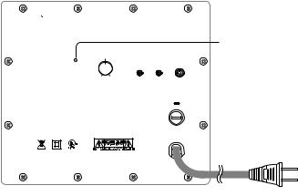
Subwoofer Controls
Power On/Auto/Standby
Plug the subwoofer AC cord into a wall outlet. We do not recommend using the outlets on the back of the receiver. Set the power switch to the desired setting.
OFF – The subwoofer is off and will not produce any sound. You may want to turn your subwoofer off if you will not be using it for some time or wish to conserve electricity.
AUTO – The subwoofer will power on whenever a signal is detected. If no signal is detected after several minutes, it will automatically enter the Standby mode.
ON – The subwoofer is always on.
An LED indicator next to the volume control indicates what mode the subwoofer is in.
OFF = The subwoofer is off
RED = STANDBY (No signal detected, Amp Off )
GREEN = ON (Signal detected, Amp On)
The subwoofer will automatically enter the Standby mode after several minutes when no signal is detected from your system. The subwoofer will then power ON instantly when a signal is detected.
Volume Control
Begin by adjusting the Subwoofer Volume Control to the 11 o’clock position. Further adjust the Subwoofer Volume Control until you hear a match in volume between the main speakers and subwoofer. Ideally, bass response should not overpower the room but rather be adjusted so there is a natural blend across the entire musical range.
Polarity Control
Selects regular (0°) or inverted (180°) polarity for the subwoofer. Set this switch to the position that provides the fullest, most dynamic bass when auditioned from the primary seating position. The effect of polarity will be most audible on low-frequency percussion instruments or music with a continuously repeating bass line, and may not produce a dramatic change at all.


 .$4
.$4
-&% *OEJDBUPS
70-6.& |
|
|
|
|
|
|
|
10-"3*5: |
-*/& */ |
|
|
0/ |
|
|
|
|
"650 |
|
|
.*/ |
."9 |
0'' |
|
|
5 " 7
5IJTEFWJDFDPNQMJFTXJUI1BSU PGUIF'$$3VMFT 0QFSBUJPOJTTVCKFDUUPUIFGPMMPXJOHUXPDPOEJUJPOTUIJTEFWJDFNBZOPUDBVTFIBSNGVMJOUFSGFSFODF BOEUIJTEFWJDFNVTUBDDFQUBOZJOUFSGFSFODFSFDFJWFE JODMVEJOHJOUFSGFSFODFUIBUNBZDBVTFVOEFTJSFEPQFSBUJPO
5IJT$MBTT#EJHJUBMBQQBSBUVTDPNQMJFTXJUI$BOBEJBO*$&4 $FUBQQBSFJMOVNÏSJRVFEFMBDMBTTF#FTUDPOGPSNFËMBOPSNF/.# EV$BOBEB
7_)[8
AUDIO/VIDEO
APPARATUS 86AC
Operation
When using the MCS 130 in a Dolby® Digital or DTS™ home theater system, make sure all speakers are set to “Small”. When using the system in a Dolby Pro Logic® home theater system, make sure the receiver’s center channel mode is set to “Normal.”
Some receivers/processors offer different setup options for each source or surround mode (e.g., CD-stereo, videotape, Dolby Digital, Dolby Pro Logic). In each case, follow your equipment’s instructions to ensure that the subwoofer output is turned on and that the speakers are set to “Small” in each mode.
If your receiver has adjustable crossover settings, we recommend the subwoofer crossover be set at 120Hz.
Refer to the owner’s manual for your AV receiver for any additional recommendations on system operation.
6

Maintenance and Service
All wiring connections should be inspected and cleaned or remade at least once a year.
If a problem does occur, make sure that all connections are properly made, secure and clean. If a problem occurs in one loudspeaker, rewire that speaker in a different location within the system. Should the problem persist in this speaker the problem is within the speaker. If the speaker sounds fine in the new position it is a strong indication of a more in depth issue with the electronics in the system. In the event that your MCS 130 ever needs service, contact your local Boston Acoustics dealer or visit www.bostona.com for a list of dealers in your area.
If your subwoofer does not play, check that all the connectors on the cables are making proper contact and that the AC plug connected to a “live” receptacle.
Limited Warranty
Boston Acoustics warrants to the original purchaser of our MCS 130 system that it will be free of defects in materials and workmanship in its mechanical parts for a period of 5 years from the date of purchase. The warranty period for the electrical components of MCS 130 is 1 year.
Your responsibilities are to install and use them according to the instructions supplied, to provide safe and secure transportation to an authorized Boston Acoustics service representative, and to present proof of purchase in the form of your sales slip when requesting service.
Excluded from this warranty is damage that results from abuse, misuse, improper installation, accidents, shipping, or repairs/ modifications by anyone other than an authorized Boston Acoustics service representative.
This warranty is limited to the Boston Acoustics product and does not cover damage to any associated equipment. This warranty does not cover the cost of removal or reinstallation. This warranty is void if the serial number has been removed or defaced. This warranty gives you specifi c legal rights, and you may also have other rights which vary from state to state.
If Service Seems Necessary
First, contact the dealer from whom you purchased the product. If that is not possible, write to:
Boston Acoustics, Inc.
300 Jubilee Drive
Peabody, MA 01960 USA
Or contact us via e-mail at: support@bostona.com
We will promptly advise you of what action to take. If it is necessary to return your MCS 130 to the factory, please ship it prepaid. After it has been repaired, we will return it freight prepaid in the United States and Canada.
For EU Customers Only
This symbol found on the product indicates that the product must not be disposed of with household waste. Instead, it may be placed in a separate collection facility for electronic waste or returned to a retailer when purchasing similar product. The producer paid to recycle this product. Doing this contributes to reuse and recycling, minimizes adverse effects on the environment and human health and avoids any fines for incorrect disposal.
Boston Acoustics continually strives to update and improve its products. The specifications and construction details are subject to change without notice.
7

INSTRUCCIONES DE SEGURIDAD IMPORTANTES
Este símbolo que aparece en el aparato indica riesgos
deri-vados de voltajes peligrosos.
Este símbolo que aparece en el aparato indica que el
usua-rio debe leer todas las declaraciones de seguri-
dad que apa-recen en el manual del usuario.
Este símbolo que aparece en el aparato indica la pres-
encia de un doble aislamiento.
1.Lea estas instrucciones.
2.Conserve estas instrucciones.
3.Haga caso de todas las advertencias.
4.Siga todas las instrucciones.
5.No utilice este aparato cerca del agua.
6.Límpielo sólo con un trapo seco.
7.No tapone ninguna apertura de ventilación. Instálelo de acuerdo con las instrucciones del fabricante.
8.No lo instale cerca de ninguna fuente de calor, tales como radiadores, rejillas de calefacción, estufas u otros aparatos (incluidos amplificadores) que produzcan calor.
9.No anule el propósito de seguridad del enchufe polarizado o del tipo puesta a tierra. Un enchufe polarizado tiene dos púas con una de ellas más ancha que la otra. Un enchufe del tipo puesta a tierra tiene dos púas y una tercera púa de puesta a tierra. La púa ancha o la tercera púa se proporciona para su seguridad. Si el enchufe que se suministra no encaja en su toma de pared, con-sulte con un electricista para que sustituya la toma de pared ob-soleta.
10.Proteja el cable de alimentación para evitar que sea pisado o quede pinzado, en particular en los enchufes, las tomas de co-rriente, y en el punto en el cual sale del aparato.
11.Utilice sólo las conexiones/accesorios especificados por el fabricante.
12.Desenchufe este aparato durante las tormentas eléctricas o cuando no vaya a utilizarse durante largos periodos de tiempo.
13.Remita todo el servicio al personal de servicio cualificado. Se requiere servicio cuando el aparato ha sido dañado de algún modo, por ejemplo si el cable de alimentación o el enchufe están dañados, si se ha vertido líquido o han caído objetos dentro del aparato, si el aparato se ha expuesto a la lluvia o a la humedad, si no funciona normalmente, o se ha caído.
14.Mantenga una distancia mínima de 50 mm alrededor de la parte delantera, trasera y de los laterales del aparato para tener una ventilación suficiente. La ventilación no debe quedar obstruida mediante la cobertura de las aperturas de ventilación o la colo-cación sobre o alrededor del aparato de elementos tales como periódicos, tapetes, cortinas, etc.
15.No deben colocarse sobre el aparato fuentes de llamas desnudas, tales como velas encendidas.
16.No debe exponerse el aparato a goteo o a salpicaduras. No deben colocarse sobre el aparato objetos llenos de líquidos, tales como jarrones.
17.Tanto el conector de entrada de energía de la parte trasera del aparato como el enchufe de pared deben ser accesibles, para
¡ADVERTENCIA! Para reducir el riesgo de incendio o de descarga eléctrica, no exponga este aparato a la lluvia o a la humedad.
Este símbolo que aparece en el aparato indica que el apa-rato debe colocarse en un punto de recogida separada para desechos electrónicos y que no debe desecharse con la ba-sura doméstica.
poder desconectar la energía del aparato.
18.Para desconectar completamente este aparato de la red de CA, desconecte el enchufe del cable de alimentación de la toma de CA.
19.La toma de red del cable de alimentación debe tener siempre un fácil acceso.
Usuarios Americanos:
Nota: Este equipo ha sido probado y ha demostrado cumplir los límites de un dispositivo digital de Clase B, según el apartado 15 de las Normas FCC. Estos límites han sido diseñados para proporcionar una protección razonable contra interferencias nocivas en una instalación doméstica. Este equipo genera, utiliza y puede radiar energía de radio frecuencia y, si no se instala y utiliza de acuerdo con las instrucciones, puede causar interferencias nocivas a las radiocomunicaciones. Sin embargo, no hay garantía de que no se producirá esta interferencia en una instalación en particular. Si este equipo causa interferencias nocivas a la recepción de radio o televisión, lo que puede determinarse apagando y encendiendo el equipo, se aconseja que el usuario trate de corregir la interferencia mediante una o más de las siguientes medidas:
•Reoriente o recoloque de la antena receptora.
•Aumente la separación entre el equipo y el receptor.
•Conecte el equipo en una toma de un circuito diferente al cual está conectado el receptor.
•Consulte con el distribuidor o un técnico de radio/TV expe-rimentado para obtener ayuda.
Usuarios Canadienses
Este aparato digital de clase B cumple con Canadian ICES-003. Este aparato digital de clase B cumple la norma NMB-003 del Canadá.
8
Especificaciones |
Altavoces LCR |
Altavoces Surround |
Subwoofer Incorporado |
|
|
|
|
Respuesta de Frecuencia: |
110Hz – 20kHz |
120Hz – 20kHz |
40 - 150Hz |
|
|
|
|
Gama de Potencia |
10 – 150 vatios |
10 – 150 vatios |
— |
Recomendada |
|
|
|
del Amplificador: |
|
|
|
|
|
|
|
Sensibilidad: |
88dB [2.8v at 1m] |
88dB [2.8v at 1m] |
— |
|
|
|
|
Impedancia Nominal: |
8 ohms |
8 ohms |
— |
|
|
|
|
Frecuencia de Cruce: |
2,700Hz |
2,700Hz |
|
|
|
|
|
Salida del Amplificador: |
— |
— |
200 vatios RMS; los circuitos |
|
|
|
BassTrac® eliminan la distor-sión |
|
|
|
|
Woofer: |
— |
— |
10” (254mm) DCD |
Gama de medios: |
DCD de copolímero dual |
|
de 31/2” (89 mm) con |
|
Tomas de Fase y |
|
MagnaGuard® |
DCD de copolímero dual |
— |
de 31/2” (89 mm) con |
|
Tomas de Fase y |
|
MagnaGuard |
|
Tweeter: |
Domo Blando de Kortec® |
Domo Blando de Kortec® |
— |
|
de 1” (25 mm) |
de 1” (25 mm) |
|
|
|
|
|
Dimensiones: (Al x An x P) |
137⁄8 x 5 x 41⁄16” |
87⁄16 x 51⁄2 x 4” |
133⁄4 x 161⁄2 x 161⁄2” |
|
(352 x 127 x 103mm) |
(214 x 140 x 102mm) |
(349 x 419 x 419mm) |
|
|
|
|
Peso: |
5 lbs |
3 lbs |
311/4 lbs |
|
(2.27kg) |
(1.36kg) |
(14.15kg) |
|
|
|
|
. |
|
|
|
Introducción al MCS 130
Gracias por comprar un Sistema de Altavoces Multicanal de Boston Acoustics. Estos altavoces incorporan componentes de alta calidad que crean el famoso sonido Boston. El MCS 130 se adapta idealmente para una utilización como una solución de canales 5.1 en un cine en casa o en un sistema musical de alta calidad. El MCS 130 se completa con todo lo que pueda necesitar para el sistema típico de altavoces, incluyendo cable para altavoces, altavoces surround, altavoces LCR (izquierdo, central y derecho), y un subwoofer. Consulte en Bostonacoustics.com\placement la información sobre la colocación de sus altavoces.
El sistema de altavoces MCS 130 presenta un diálogo en pantalla excepcionalmente articulado, música, efectos y graves en- volven-tes en un conjunto pequeño y elegante. La colocación compacta de cada altavoz y las frecuencias de cruce de calidad y específicas del sistema aseguran una amplia dispersión uniforme para una cobertura total de la sala de escucha. Todos
los altavoces presentan también el blindaje magnético MagnaGuard® que asegura que el campo magnético del altavoz no interfi era con las imágenes de televisión.
9
Desembalaje del Sistema
Desembale cuidadosamente el sistema. Si hay alguna señal de daños debidos al transporte, informe de ello inmediatamente a su distribuidor y/o a su servicio de entrega. Conserve el cartón de envío y los materiales de embalaje para una futura utilización.
Abra el paquete y verifique que contiene los siguientes elementos:
(3)Altavoces LCR (izquierdo, central, derecho)
(2)Altavoces surround
(1)Subwoofer
(2)Cables de altavoz de 40’’ (12 m)
(3)Cables de altavoz de 15’’ (4,6 m)
(1)Cables de subwoofer de 15’’ (4,6 m)
(2)Pies (para utilización en caso de utilización de los altavoces LCR)
(4)Amortiguadores de caucho
(utilizados en el montaje mural)
(3) Altavoces LCR S
con pies extraíbles
(2) Altavoces surround |
Subwoofer |
|
con pies extraíbles |
||
|
Opciones de Colocación
Los altavoces LCR y surround del MCS 130 son fáciles de situar en sobremesa o en montaje mural. Los altavoces están configurados para ser utilizados en sobremesa al desembalar
por primera vez el sistema. Dos altavoces LCR tendrán montado un pie que lo mantendrá nivelado cuando se utilice en posición vertical. El otro altavoz LCR tendrá montados 2 pies para su utilización como altavoz central. Hay dos grupos de orificios en cada pie; si se utiliza el orificio superior, los altavoces tendrán un ligero ángulo hacia delante para su utilización en un estante elevado. Si se retiran los pies de la parte trasera de los altavoces, éstos son fáciles de montar en la pared.
Los altavoces LCR y surround del MCS 130 están diseñados para un fácil montaje mural utilizando la(s) ranura(s) de bocallave de la parte trasera del altavoz. Al montar los altavoces en la pared utilice los amortiguadores de caucho suministrados. Para el montaje mural de los altavoces debe retirar el pie que está sujeto a los mismos. Retire el tornillo de palometa de la parte trasera del pie. Está ranurado para poder retirarlo fácilmente con un destorni-llador o una moneda.
La opción de montaje con bocallave es similar al proceso de colgado de un cuadro en una pared. Monte un tornillo #8 (no incluido) en la tablaroca, asegurándose de que entre en un pasador, y cuelgue el altavoz de la cabeza del tornillo. Si no se dispone de pasador, debe utilizarse un anclaje de tablaroca para aguantar el peso del altavoz. Es aconsejable conectar el cable del altavoz antes del montaje mural.
NOTA: Debido a que existen muchos tipos diferentes de superficies en las cuales pueden montarse los altavoces, no hay ningún tipo de sujeción que podamos suministrar que funcione en todas
las situaciones posibles. Por lo tanto, compre el tipo de sujeción apropiado teniendo en cuenta la superficie en la cual se va a montar el altavoz. Si no está seguro del tipo de sujeción que debe utilizar, lleve el soporte de montaje a una ferretería de confianza, hábleles de la pared en la cual va a montar el altavoz, y pída-les que le recomienden una sujeción apropiada. Tenga en cuenta el peso del altavoz.
Utilice el orificio de tornillo


 inferior para la posición
normal del altavoz; utilice el
orificio de tornillo superior para inclinar el altavoz
hacia delante.
Amortiguador de caucho
Montaje con bocallave
Amortiguadores de caucho
10
Conexiones del Altavoz
Después de que los altavoces estén colocados adecuadamente, está preparado para cablear su sistema. Primero, apague la energía del sistema. Utilice el cable de altavoz incluido en el sistema para realizar las conexiones. Utilice la ilustración siguiente como guía sobre la conexión de los cables a los satélites y al canal central del MCS 130
Para la conexión de su receptor, consulte su manual de usuario.
¡Importante!
Para asegurar el mejor rendimiento observe las polaridades al realizar las conexiones del altavoz, como se muestra en la ilustración. Conecte cada terminal + de la parte trasera del amplificador o receptor al respectivo terminal + (rojo) de cada altavoz. Conecte los terminales – (negros) de la misma forma. Si las conexiones no se realizan correctamente puede provocar una respuesta de graves y una imagen pobres. Igualmente, para evitar cortocircuitos que pueden dañar su equipo, tenga cuidado de no permitir que dos cables desnudos se toquen.
Asegúrese de mantener la polari-dad + y – adecuada en todas las conexiones de cables de altavoz.
Los cables de altavoz pueden ser enca-minados a través de los canales de la parte trasera del altavoz y los orificios de los pies.
Conexiones del Subwoofer
Desconecte toda la potencia. Utilice el cable de subwoofer incluido con el sistema para conectar el subwoofer a la salida Subwoofer o LFE de su receptor. Conecte el otro extremo a la toma “Line In” en la parte trasera del Subwoofer.


 .$4
.$4
70-6.& |
|
|
|
|
|
|
|
10-"3*5: |
-*/& */ |
|
|
0/ |
|
|
|
|
"650 |
|
|
.*/ |
."9 |
0'' |
|
|
5 " 7
5IJTEFWJDFDPNQMJFTXJUI1BSU PGUIF'$$3VMFT 0QFSBUJPOJTTVCKFDUUPUIFGPMMPXJOHUXPDPOEJUJPOTUIJTEFWJDFNBZOPUDBVTFIBSNGVMJOUFSGFSFODF BOEUIJTEFWJDFNVTUBDDFQUBOZJOUFSGFSFODFSFDFJWFE JODMVEJOHJOUFSGFSFODFUIBUNBZDBVTFVOEFTJSFEPQFSBUJPO
5IJT$MBTT#EJHJUBMBQQBSBUVTDPNQMJFTXJUI$BOBEJBO*$&4 $FUBQQBSFJMOVNÏSJRVFEFMBDMBTTF#FTUDPOGPSNFËMBOPSNF/.# EV$BOBEB
7_)[8
AUDIO/VIDEO
APPARATUS 86AC
11
Controles del Subwoofer
Conexión/Auto/Standby
Enchufe el cable de CA del subwoofer en una toma de pared. No recomendamos utilizar las tomas de salida de la parte trasera del receptor. Ajuste el interruptor de potencia en el control deseado.
OFF – El subwoofer está apagado y no producirá ningún sonido. Puede querer apagar su subwoofer si no lo va a utilizar durante algún tiempo o si desea no gastar electricidad.
AUTO – El subwoofer se encenderá siempre que se detecte una señal. Si no se detecta una señal después de varios minutos, entrará au-tomáticamente en el modo Standby.
ON – El subwoofer está siempre encendido.
Un indicador de LED junto al control de volumen indica el modo en el cual se encuentra el subwoofer. OFF = El subwoofer está apagado
ROJO = STANDBY (No hay detección de señal, Amp Apagado) VERDE = ON (Detección de señal, Amp Encendido)
El subwoofer se pondrá automáticamente en el modo “Standby” después de varios minutos si no se detecta una señal desde el sistema. El sub-woofer se CONECTARÁ instantáneamente cuando se detecte una señal.
Control del Volumen
Empiece ajustando el Control de Volumen del Subwoofer a la posición de las 11 del reloj. Después siga ajustando el Control de Volumen del Subwoofer hasta que escuche una correspondencia entre el volumen de los altavoces principales y el del subwoofer. Idealmente, la respuesta de graves no debe sobrecargar la sala, sino más bien ajustarse de forma que haya una mezcla natural a lo largo de toda la gama musical.
Control de Polaridad
Seleccione la polaridad normal (0°) o invertida (180°) para el subwoofer. Ajuste este conmutador a la posición que proporcione los graves más llenos y más dinámicos cuando esté escuchando desde la posición de escucha principal. El efecto de la polaridad será más audible en instru-mentos de percusión de baja frecuencia o en música con una línea de graves continuamente repetida, y puede no producir ningún cambio significativo en realidad.


 MCS 130
Indicador de LED
VOLUME
|
|
|
POLARITY |
LINE IN |
|
|
ON |
180º |
|
|
|
AUTO |
|
|
MIN |
MAX |
OFF |
0º |
|
T2.5A/250V
This device complies with Part 15 of the FCC Rules. Operation is subject to the following two conditions:
(1)this device may not cause harmful interference, and
(2)this device must accept any interference received, including interference that may cause undesired operation.
This Class B digital apparatus complies with Canadian ICES-003.
Cet appareil numérique de la classe B est conforme à la norme NMB-003 du Canada.
120V~
60Hz 300W
AUDIO/VIDEO
APPARATUS 86AC
Funcionamiento
Cuando utilice el MCS 130 en un sistema de cine en casa Dolby® Digital o DTS™, asegúrese de que todos los altavoces están ajustados en “Small”. Cuando utilice el sistema en un sistema de cine en casa Dolby Pro Logic®, asegúrese de que el modo del canal central del receptor está ajustado en “Normal.”
Algunos receptores/procesadores ofrecen diferentes opciones de configuración para cada fuente o modo “surround” (envolvente) (p. ej. CD estéreo, videocasete, Dolby Digital, Pro Logic). En cada caso, siga las instrucciones de su equipo para asegurarse de que la salida del subwoo-fer está conectada y que los altavoces están ajustados en “Small” en cada modo.
Si su receptor tiene ajustes de frecuencia de cruce ajustables, recomendamos que la frecuencia de cruce del subwoofer se ajuste en 120 Hz.
Remítase al manual del propietario de su receptor AV para obtener cualquier recomendación adicional sobre el funcionamiento del sistema.
12
 Loading...