

Page 1
142-003708-0
GT-RSL
Remote Subwoofer Level Controller for GT Ampliers
Boston Acoustics, Inc. 300 Jubilee Drive, Peabody, MA 01960 USA
T: 978.538.5000 F: 978.538.5100 W: bostonacoustics.com
Boston, Boston Acoustics, Boston GT, and the Boston Acoustics logo are registered
trademarks of Boston Acoustics, Inc. Specications are subject to change without
notice. © 2009 Boston Acoustics, Inc. All rights reserved. Covered by patents issued
and/or pending.
Page 2
PACKAGE CONTENTS
The GT-RSL is supplied with the following items:
• RSL Controller Unit (knob, 13ft cable, mounting bracket)
• Mounting Screws for Controller unit
• RSL Controller VCA Board
• RSL Port Cover and Pre Attached Mounting Screws
YOU WILL NEED
• #1 Phillips Head Screwdriver
• 3mm Allen Wrench (for removing the GT amplier top cover)
OPERATION
• Clockwise rotation will increase the subwoofer level.
• Counterclockwise rotation will decrease the subwoofer level.
• It may be necessary to reset the input sensitivity on the subwoofer amplier
according to user preference and or musical material.
• No other adjustments are required after the initial installation and setup.
Note: The GT-RSL is compatible with the
GT-5750, GT-4100, GT-2300, GT-2200, GT-475,
GT-2125, GT-50, GT-42, GT-40, GT-28, and GT-24
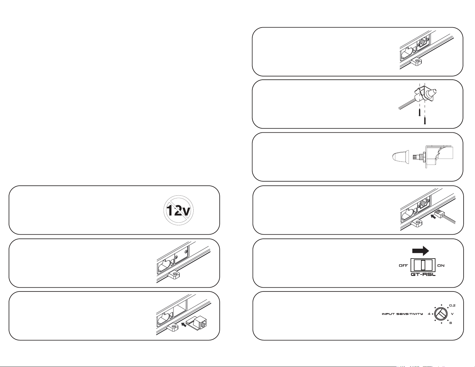
INSTALLATION INSTRUCTIONS
1. Completely power down the audio system
in the vehicle and remove the negative
cable from the vehicle's battery.
4. Install the GT-RSL cover plate over the
socket and tighten screws.
5.
Determine a location for the RSL control
in the front of the vehicle. Screws are
supplied for the GT-RSL bracket mounting.
6. The GT-RSL can be removed from bracket
mount for ush installation by sliding knob
o and removing attachment nut.
Cut out diameter is ⁄
7. Route cable through the vehicle to the
" (7mm)
amplier’s location. Slide the connector
into the GT-RSL receptacle on the GT amplier.
2. Remove (2) screws securing amplier
GT-RSL cover plate marked “GT-RSL”.
3. Align the GT-RSL Control PC Board into
the port slots on the amplier and gently
press into the place until seated. The GT-RSL
PC Board should t into amplier without force.
8.
On the amplier, move the “GT-RSL”
switch to the “on” position.
9. Reconnect power to the vehicle. It may
be desirable to readjust the gain on the
amplier to allow for greater range of
adjustment from the GT-RSL.
 Loading...