

Boston Acoustics G512, G5 Series, G510, GTR, G51244 Specifications
...
042-001933-0
G5 - High Performance Subwoofers
GTR - TunableRadiators
™
G5 Specifications/Enclosure Recommendations
Model: G51244 G5124 G51044 G5104
Nominal Size: 12" 12" 10" 10"
RMS Power Handling: 450w 450w 450w 450w
Impedance: Dual 4ΩSingle 4ΩDual 4ΩSingle 4
Ω
Frequency Response: 20-350Hz 20-350Hz 24-350Hz 24-350Hz
(+/-3dB in car)
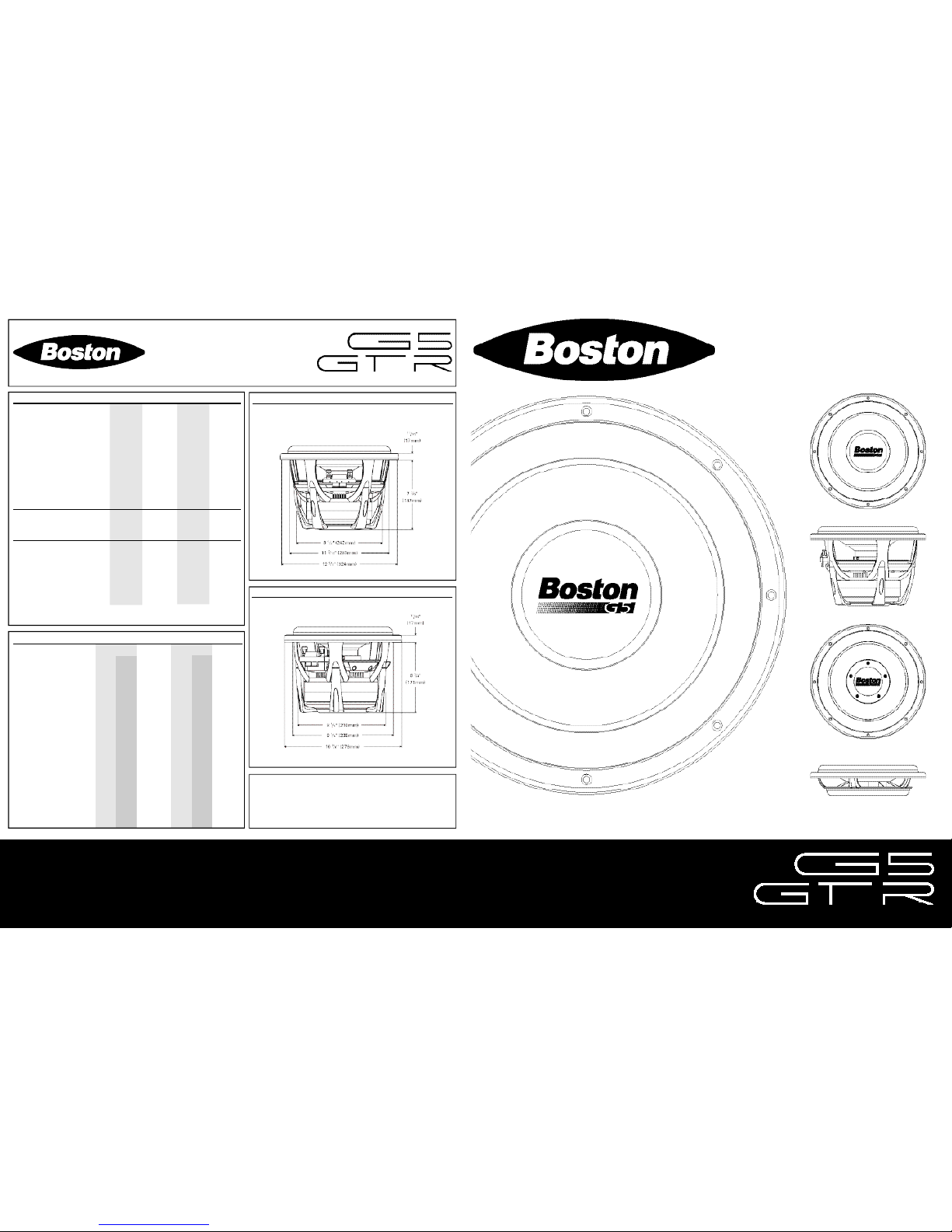
Mounting Cutout Diameter: 11 3/16" 11 3/16" 9 1/4" 9 1/4"
(283mm) (283mm) (235mm) (235mm)
Mounting Depth: 7 3/8" 7 3/8" 6 3/4" 6 3/4"
(187mm) (187mm) (171mm) (171mm)
Recommended Sealed 1.0 ft31.0 ft30.5 ft30.5 ft
3
Enclosure Volume*: (28.3L) (28.3L) (14.2L) (14.2L)
Q-Tune
™
†
: (HP & Q Setting) 2 8 H z @ 0 . 7 2 8 H z @ 0 . 7 33Hz@0.7 3 3 H z @ 0 . 7
Recommended Ported 2.0 ft32.0 ft31.3 ft31.3 ft
3
Enclosure Volume*: (56.6L) (56.6L) (36.8L) (36.8L)
Vent Diameter: 4" (10cm) 4" (10cm) 3" (7.6cm) 3" (7.6cm)
Vent Length: 14" (36cm) 14" (36cm) 11" (28cm) 1 1 " ( 2 8 c m )
Tuning Frequency: 33Hz 33Hz 34Hz 34Hz
Q-Tune
™
†
: (HP & Q Setting) 3 3 H z @ 1 . 0 3 3 H z @ 1 . 0 34Hz@0.9 3 4 H z @ 0 . 9
*Enclosure volumes include basket and port displacement
†Q-Tune™is a feature found on Boston GT Amplifiers
G5 Thiele-Small Parameters
Model: G512-44 G512-4 G510-44 G510-4
P a r a l l e l S e r i e s P a r a l l e l S e r i e s
Fs: (Hz) 28.88 28.88 29.65 32.37 32.37 34.51
Re: (Ohms) 1 . 5 5 6 . 2 0 3.33 1 . 5 4 6 . 1 6 3.28
Qms: 9.93 9.93 9.94 9.19 9.19 10.47
Qes: 0.49 0.49 0.62 0.50 0.50 0.58
Qts: 0.47 0.47 0.58 0.47 0.47 0.55
Vas: (Liters) 75.28 75.28 74.53 29.77 29.77 29.54
Mms: (Grams) 148.5 148.5 135.8 122.4 122.4 109.4
Cms: (µM/Newton) 215 215 213 198 198 197
Xmax: (Mm) 15.0 15.0 15.3 15.0 15.0 15.3
Xmech: (Mm) 45.0 45.0 45.0 45.0 45.0 45.0
Sd: (CM 2) 499 499 499 327 327 327
Bl: (Tesla-M) 9 . 1 5 1 8 .30 11.72 8 . 7 6 1 7 . 5 2 11.60
SPL Eff: (dB @ 1w/1m) 87.2 87.2 86.8 84.9 84.9 85.0
SPL Sen: (dB @ 2.83v) 9 4 . 3 8 8 . 3 9 0 . 6 9 2 . 0 8 6 . 0 8 8 . 9
Boston Acoustics, Inc. 300 Jubilee Drive, Peabody, MA 01960 USA
T: 978.538.5000 F: 978.538.5100 W: bostonacoustics.com
Q-Tune, SureSet, and TunableRadiator are trademarks and Boston, Boston
Acoustics, and the Boston Acoustics logo are registered trademarks of Boston
Acoustics, Inc. Specifications are subject to change without notice.
All rights reserved. Covered by patents issued and/or pending.
© 2004 Boston Acoustics, Inc.
G512 Basket Dimensions
G510 Basket Dimensions
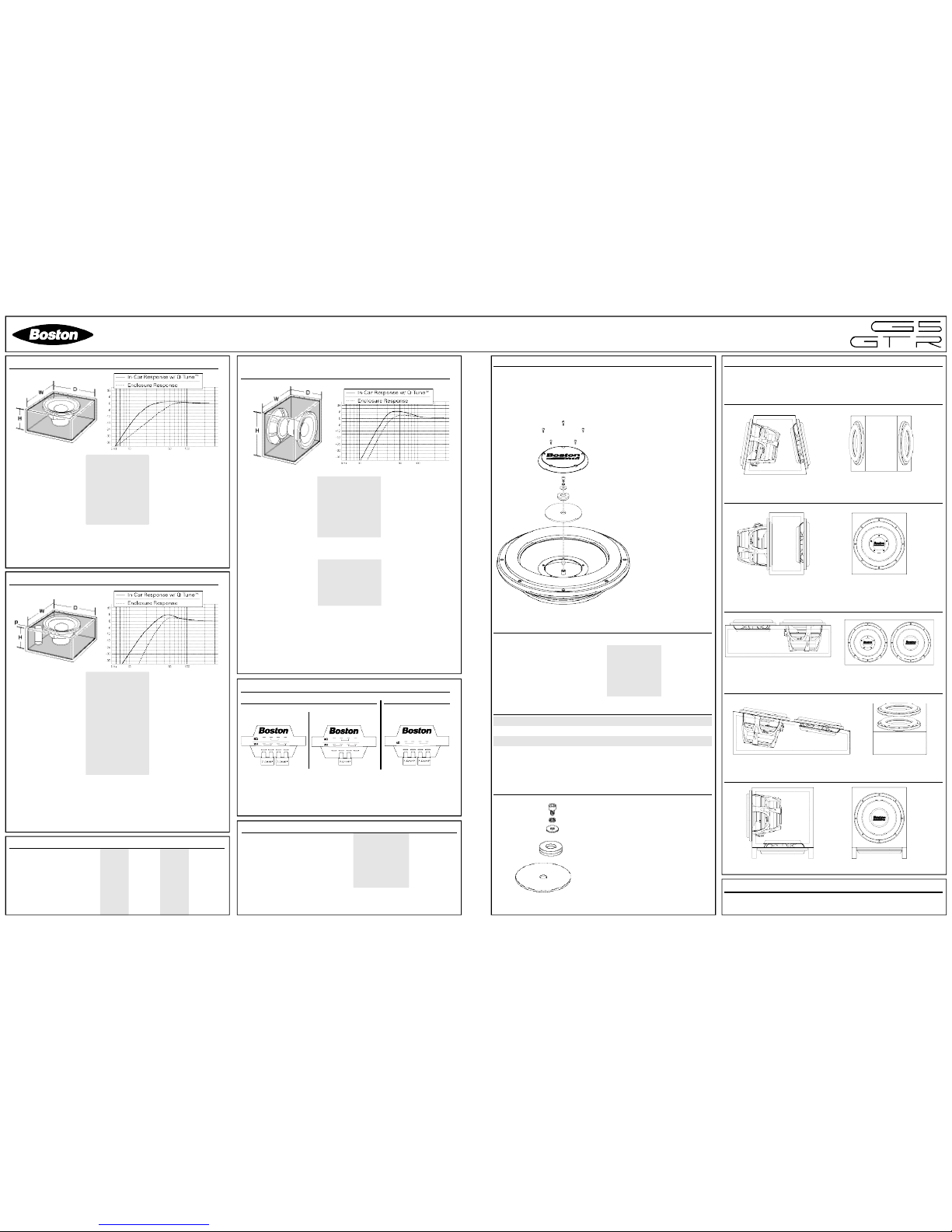
Single G5 Enclosure Design Example - Ported
Model: G512" G510"
H = Height: 15.5" (39.8cm) 12" (30.5cm)
W = Width: 16.5" (42.0cm) 13.25" (33.7cm)
D = Depth: 14" (35.6cm) 14" (35.6cm)
P = Port Clearance*: 4" (10cm) 3" (7.6cm)
Gross Volume: 2.0 Ft3(56.6L) 1.3 Ft3(36.8L)
Port Diameter: 4" (10cm) 3" (7.6cm)
Port Length: 14" (36cm) 11" (28cm)
Q-Tune
™
†
: (HP & Q) 33Hz@1.0 34Hz@1.0
Enclosure dimensions are internal and include basket and port displacement
This enclosure shape is an example and these dimensions can be modified provided that the
exact internal volume is retained and that there is adequate space behind the vent (diameter
of port from the back and side walls)
3
⁄4-inch thick M.D.F. is recommended as a minimum
*Recommended distance from sides and back walls of enclosure
†Q-Tune™is a feature found on Boston GT Amplifiers
Single G5 Enclosure Design Example - Sealed
Model: G512" G10"
H = Height: 10.5" (26.7cm) 7.5" (19.1cm)
W = Width: 13.0" (33.1cm) 11.0" (28.0cm)
D = Depth: 13.0" (33.1cm) 11.0" (28.0cm)
Gross Volume: 1.0 Ft3(28.3L) 0.5 Ft3(14.2L)
Q-Tune
™
†
: (HP & Q) 28Hz@0.707 33Hz@0.707
Enclosure dimensions are internal and include basket displacement
This enclosure shape is an example and these dimensions can be modified provided that the
exact internal volume is retained
3
⁄4-inch thick M.D.F. is recommended as a minimum
†Q-Tune™is a feature found on Boston GT Amplifiers
SureSet™Fuse Configurations
G5124 / G5104G51244 / G51044
G5 Included Hardware
Model: G21244 G2124 G21044 G2104
Hex Key 2.5mm 1 1 1 1
7.5-Amp Fuse: 2 2 2 2
T-Nut M4: 8 8 8 8
Lock Washer M4: 8 8 8 8
Mounting Screw M4: 8 8 8 8
Wood Screw M4 x 38mm: 8 8 8 8
Note: The SureSet™feature utilizes standar d au tomotive ATC fus es to
select between series or p arallel voice-coil operation (DVC only). T he
fuses also provide voice-coil protection under transien t conditions such
as accidental momentary overdrive. The fuses will not protect against
voice-coil f ailure resulting fro m long term high po wer abuse.
2-ohm operation 8-ohm operation 4-ohm
Single G5 Enclosure Design Example
- GTR Tu n a b l e R a d i a t o r
™
Model: G512" w/ GTR12 G510" w/ GTR10
H = Height: 13" (33.0cm) 9.5" (24.1cm)
W = Width: 13" (33.0cm) 9.5" (24.1cm)
D = Depth: 10.5" (266.7cm) 9.75" (24.8cm)
Gross Volume: 1.0 Ft3(28.3L) 0.5 Ft3(14.2L)
GTR Tuning / Q-Tune™Setting Matrix:
Model: G512" w/ GTR12 G510" w/ GTR10
Tuning Mode 1: 45Hz / 42Hz@0.7 50Hz / 45Hz@0.7
Tuning Mode 2•: 35Hz / 34Hz@1.0 35Hz / 34Hz@1.0
Tuning Mode 3: 30Hz / 30Hz@1.2 30Hz / 30Hz@1.2
Enclosure dimensions are internal and include basket and GTR displacement
These enclosure shapes are examples and these dimensions can be modified provided that
the exact internal volume is retained and that there is adequate space behind the woofer and
the GTR.
3
⁄4-inch thick M.D.F. is recommended as a minimum
*Recommended distance from sides and back walls of enclosure
†Q-Tune™ is a feature found on Boston GT Amplifiers
•
Factory Tuning Mode
G5 w/ GTR Enclosure Shape Examples
GTR TunableRadiator™Included Hardware
Model: GTR12 GTR10
Hex Key 2.5mm 1 1
T-Nut M4: 8 8
Lock Washer M4: 8 8
Mounting Screw M4: 8 8
Wood Screw M4 x 38mm: 8 8
Also included with all GTR TunableRadiators™is the GTR Tuning Hardware, these parts are
individually listed in the GTR TunableRadiator™Tuning Hardware section.
GTR TunableRadiator™Tuning Hardware
Small Tuning Mass*
2 x Large Tuning Mass
(1 installed* / 1 in hardware pack)
Screw*
Lock Washer*
Washer*
*Pre-installed on GTR from factory
GTR TunableRadiator™Tuning Frequency Chart
For single recommended G5/GTR enclosures
Tuning Mode: GTR12 GTR10
Enclosure Volume: 1.0 Ft
3
0.5 Ft
3
Tuning Mode 1: 45Hz 49Hz
Tuning Mode 2: 35Hz 35Hz
Tuning Mode 3: 30Hz 30Hz
Weight Chart Small Tuning Mass Large Tuning Mass
Tuning Mode 1: X X
Tuning Mode 2: 1 1
Tuning Mode 3: X 2
Key:
X = No Mass Used
1 = One Mass Used
2 = Two Mass Used
Changing the tuning on the GTR TunableRadiators
™
Note: The GTR TunableRadiator™is shipped from the factory in “Tuning Mode #2”.
1.Remove the dustcap.
2.Remove the center screw, lock
washer, and washer that hold the
mass to the GTR.
3.Select the desired tuning mode by
placing the correct combination of
mass, foam side down, on the
center shaft. (use the tuning guide
located below)
4.Insta ll the cen ter screw, lock
washer, and washer and tighten.
5.Install the dustcap using all five
screws.
Warning: The dustcap is
a structural part of the
GTR Tu n a b l e R a d i a t o r
™
and must b e ins talled
before use.
Trapezoid
Rectangle
SPS™Removal and Installation
Please refer to the SPS™Removal / Installation instruction sheet for
information on disassembly and installation of the SPS™.
Reverse
Listed below are several single G5 subwoofer using a GTR
TunableRadiator™enclosure shape examples.
FrontTop
Side Top
Side Front
Side Top
Wedge
Side Front
Square with Down-firing GTR
 Loading...