

Boston Acoustics GTA 1105 Installation Manual
High Performance
5 Channel Amplier
GTA
Specifications
2
Introduction
T
hank you for choosing Boston Acoustics and congratulations, you’ve
made the right choice. You’re now equipped for the open road. Your high
performance GTA amplifiers are engineered to perform and built to last.
These products represent the pinnacle of performance and innovation that
Boston Acoustics is famous for. We hope you enjoy your amplifier and the
road ahead.
Technical Specifications:
Front & Rear Channels Subwoofer Channel
Rated Power (CEA-2006-A):
@ 4-Ohm (Stereo): 70 Watts x 4 N/A
@ 2-Ohm (Stereo): 125 Watts x 4 N/A
@ 4-Ohm (Mono): 250 Watts x 2 250 Watts x 1
@ 2-Ohm (Mono): N/A 400 Watts x 1
Impedance Stability: 2Ω St / 4Ω Mono 2Ω
Frequency Response (-3dB): 10Hz–50kHz 10Hz–150Hz
Signal-to-Noise Ratio: >90dB >90dB
(A Weighted)
THD+N: 1% 1%
Highpass Crossover:
Frequency Range: 50Hz - 200Hz 10Hz - 50Hz
Slope (dB Per Octave): 12dB 12dB
Lowpass Crossover:
Frequency Range: 50Hz - 200Hz 50Hz - 150Hz
Slope (dB Per Octave): 12dB 12dB
Signal Voltage Input Range:
Low Level (RCA) Input: 200mv - 5v
Speaker Level Input: 400mv - 10v
Fuse Amp Rating (ATC): 3 x 25 Amp
Dimensions:
Width: 21
1
⁄4” (538mm)
Height: 23⁄8” (60mm)
Depth: 8 3⁄8” (211mm)
Parts List:
Owners Manual: x 1
2mm Hex Wrench: x 1
3mm Hex Wrench: x 1
4mm Hex W
rench:
x 1
Speaker Level Input Cable:
x 1
Mounting Screws: x 4
Replacement Fuses (A
TC):
x 3 (25 amp)
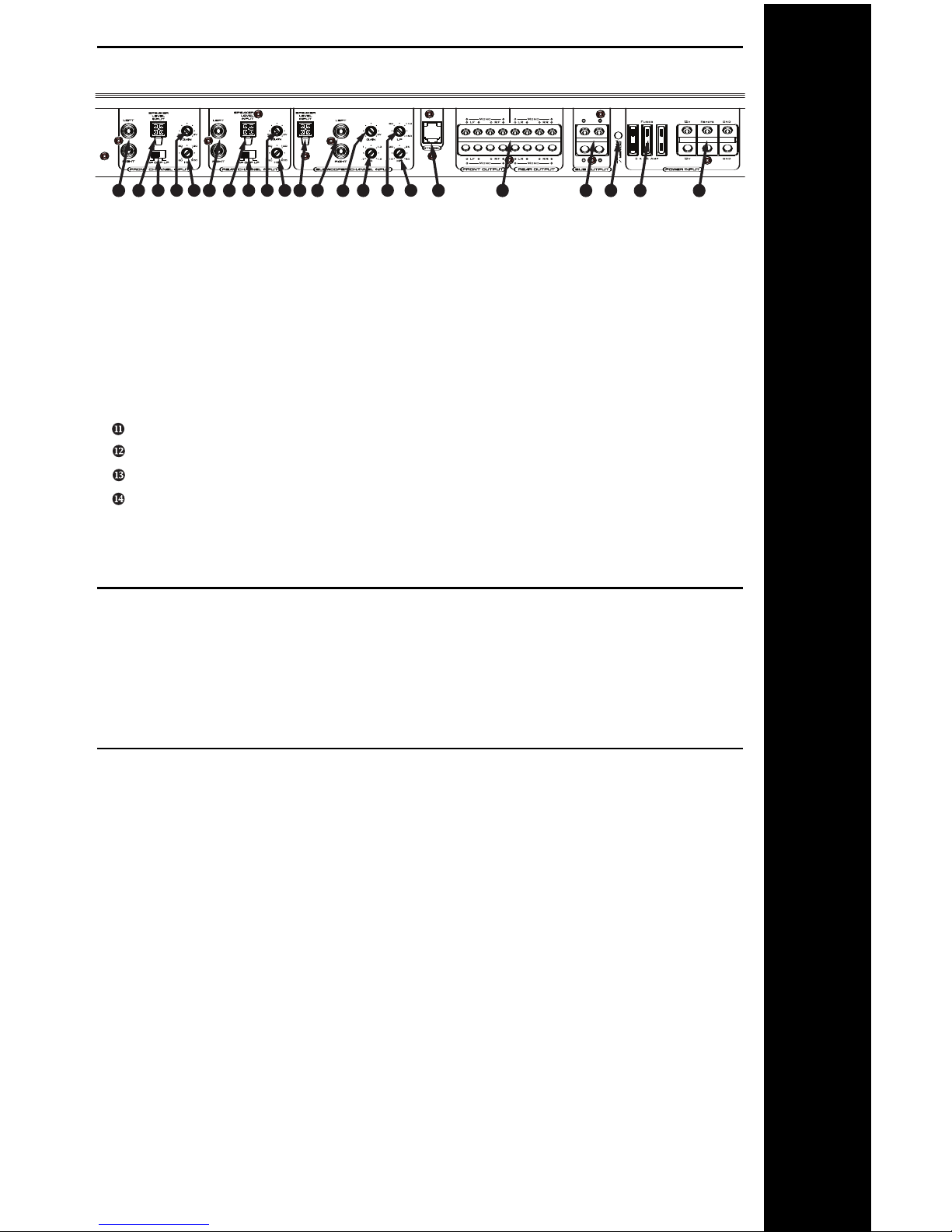
Connections / Controls
3
Status LED
The Boston Logo will illuminate “Blue” under normal operating conditions.
The LED will illuminate “Red” during start-up and under fault conditions. If the
LED is still red after start-up, please refer to troubleshooting on page 10.
u RCA Input (Left and Right)Speaker Level Input
v Speaker Level Input
w Crosssover Filter Switch (HP / Off / LP)
x Gain (250mv to 5.0v - continuously variable)
y Crossover Frequency Adjustment (50Hz to 200Hz - continuously variable)
z Q-Tune™“Q” Adjustment (0.707 to 1.6 - cont. variable)
{ Lowpass Crossover Adjustment (50Hz to 150Hz - cont. variable))
| Q-Tune™Highpass (Subsonic) Adjustment (10Hz to 50Hz - cont. variable)
} GTA-RSL Port (Remote Gain)
~ Speaker Output Block (Front and Rear Speakers)
Speaker Output Block (Subwoofer)
Status LED (Blue = Normal / Red = Fault Mode)
Fuses (Replace with same value only, refer to specifications on page 2)
Power Block (12v / Remote / Ground)
4
4 7
1 2
6
1210 11
13 14
9
2 1
3 5
4
1
2
3 5 8
Connections and Controls
Speaker Level Input Cable
GTA amplifiers offer a dedicated speaker level input for ease installation into
factory systems when an RCA (low level) signal is not available. Wiring code for
the cable is industry standard;
White Solid = Left Positive White w/ Black Stripe = Left Negative
Gray Solid = Right Positive Gray w/ Black Stripe = Right Negative
Warning: Do not connect both Speaker Level and RCAs into the amplifier at the
same time as damage to the amplifier may occur.

Installation - General
4
WARNING! Before driving the amplifier mounting screws through any surface,
be sure of what is behind that surface. Check for the gas tank, brake lines, and
any vehicle wiring harness. Never run wires outside or under the vehicle or
where they could become broken or interfere with the safe operation of the
vehicle.
Before You Install
Before you install the unit, disconnect the negative (–) battery cable in the
engine compartment of the vehicle. Doing so will prevent damage to both the
electrical system of the vehicle and the amplifier during installation.
Battery and Charging System
In order for the amplifier to function correctly, the electrical system of the
vehicle should be professionally checked for overall electrical capacity. When
used, the amplifier will increase the demand on the battery and alternator.
Therefore, both should be thoroughly evaluated before installing the amplifier
to ensure they are in normal operating condition and able to handle the
increased demand the amplifier will present to the vehicle’s electrical system.
Wire Routing
Do not run the power wire near any low-level signals or audio cables such as
the RCAs from the head unit. Noise can be introduced into the amplifier when
this occurs. It is helpful to diagram the wire layout first before any installation
is initiated.
Choose the Mounting Location
Plan your installation so that the amplifier is mounted where adequate
ventilation is available. Never mount an amplifier in the engine compartment
of a vehicle!
Passenger and Trunk Compartment Mounting
If the amplifier is mounted under a seat, be sure that there is adequate space
around the amplifier once installed, 1” (25mm) recommended minimum. Do not
allow seat padding or other obstructive material to press down on the amplifier.
When mounting in a trunk, choose a location that will be protected from sliding
cargo or other materials. Mount the amplifier to solid surfaces only. Do not
mount to plastic trim panels. Do not mount the amplifier with V
elcro, double-stick
tape, or by wedging into position. Amplifier should be mounted using the screw
mounts in the endpanels and with the provided mounting screws.
Cooling
Position the amplifier so that there is adequate space around the amplifier once
installed, 1” (25mm) recommended minimum.
Installation - General
 Loading...