

Boston Acoustics GT-40 User Manual
4-Channel, High-Current/High-Power Amplifier
GT-40_manual 4/10/03 4:17 PM Page 1
GT-40
us
t
Sta
On
e
f
a
S

2
Table of Contents
Parts List 3
Features and Specifications 3
Control Functions 4
Control functions (cont.) 5
Control functions (cont.) 6
Mechanical Functions 6
Control cover removal & reinstallation 6
Multi-position mounting feet 6
Mechanical functions (cont.) 7
Amplifier linking 7
Wire connection 7
Fuses 7
General Installation Precautions 8
Before you install 8
Battery & charging system 8
Wire routing 8
Installation—Amplifier Mounting 9
Choose the mounting location 9
Installation—amplifier mounting (cont.) 10
Passenger & trunk compartment mounting 10
Installation—Fuses & Wiring 10
Amplifier fuses 10
Wire gauge 10
Installation—fuses & wiring (cont.) 11
Power/B+ & power/ground connection 11
Remote input connection 11
Speaker output connection 11
Installation—fuses & wiring (cont.) 12
Mono subwoofer operation 12
Setup Tuning—Full-range Speakers 12
Music 12
Front & rear sensitivity controls 12
Front & rear crossover controls 12
Setup tuning—full-range speakers (cont.) 13
Head unit 13
Volume 13
Front input sensitivity control 13
Front crossover controls 13
Setup tuning—full-range speakers (cont.) 14
Q-factor adjustments 14
Rear input sensitivity & crossover controls 14
Setup Tuning—Rear Fill Speakers & Subwoofers 14
Subwoofer level control 14
Rear input switch 14
Setup tuning—rear fill speakers & subwoofers (cont.) 14
Head unit 15
Volume 15
Rear input sensitivity control 15
Rear crossover control 15
Phase 15
System Examples 16,17
Amplifier Troubleshooting Guide 18
Contact and Warranty Information 19
GT-40_manual 4/10/03 4:17 PM Page 2
Included Hardware
(1) owner’s manual
(1) female quick-connect terminal for remote input
(1) 2mm hex wrench (for speaker input)
(1) 3mm hex wrench (for power input)
(4) mounting screws
3
Parts List
GT-40Specifications
14.4VDC Power
@ 4 Ohms 4x55W
@ 2 Ohms 4x90W
@ 4 Ohms (dual-mono) 2x190W
@ 2 Ohms (dual-mono) 2x240W
12.6VDC Power
@ 4 Ohms 4x45W
@ 2 Ohms 4x70W
@ 4 Ohms (dual-mono) 2x140W
@ 2 Ohms (dual-mono) 2x190W
14.4VDC Multi-channel Power 2x55W (4 ohm), 1x240W (2 ohm)
12.6VDC Multi-channel Power 2x45W (4 ohm), 1x190W (2 ohm)
Frequency Response (-3dB) 10Hz–95kHz
Signal-to-Noise Ratio (A Weighted) >100dB
Dimensions 21/4x141/8x87/8” (57 x 358 x 225mm)
GT-40 Features
4-Channel, High-Current Amplifier
2Ω Bridge Stable Operation
Power Increase with Input Voltage Rise
Advanced Cooling Allows Varied Mounting Positions
Adjustable Feet for Varied Mounting Surfaces
Security Cover Protects Control Settings
Continuously Variable Crossover and Q-factor Settings
Selectable Highpass Front Channels
Selectable Mono/Stereo Rear Highpass (Rear Fill) or
Subwoofer Lowpass
Selectable Rear Channel Signal Derived from Front Channel Input
Optional Remote Bass Control
Enhanced Switching Assignments
Features and Specifications
GT-40_manual 4/10/03 4:17 PM Page 3
4
Control Functions
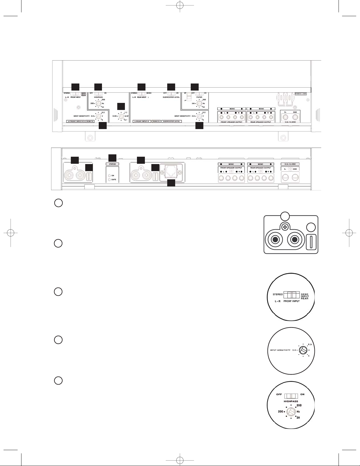
FRONT RCA Inputs
RCA cables marked “FRONT” from head unit or from other line level device
should be connected here. Use both inputs (L & R) for stereo.
FRONT Remote Input
Use the supplied FEMALE quick connector to connect the REMOTE trigger lead
from the head unit to the amplifier. Amplifier turns “ON” when head unit is turned
“ON.” One FEMALE .210" connector is supplied with amplifier.
FRONT Input Switch
In the left position, the L & R inputs go to the FRONT L & R channels of the amplifier. In the right position, the L & R inputs go to the FRONT and REAR L & R chan-
nels of the amplifier.
FRONT and REAR Sensitivity
Tu rn control clockwise to increase the amplifier sensitivity to incoming signals. Turn
control counterclockwise to decrease the amplifier sensitivity.
FRONT Highpass Crossover Controls
To use 12dB/octave crossover, move switch to right-hand position. Highpass
crossover frequency is adjustable from 20Hz to 350Hz by rotary control. (Moving
switch to left-hand position will bypass crossover functions.)
1
2
1
2
3
4
5
12
4
9
8
7
6
53
2
1
11
10
12
4
GT-40_manual 4/10/03 4:17 PM Page 4
5
Control Functions (cont.)
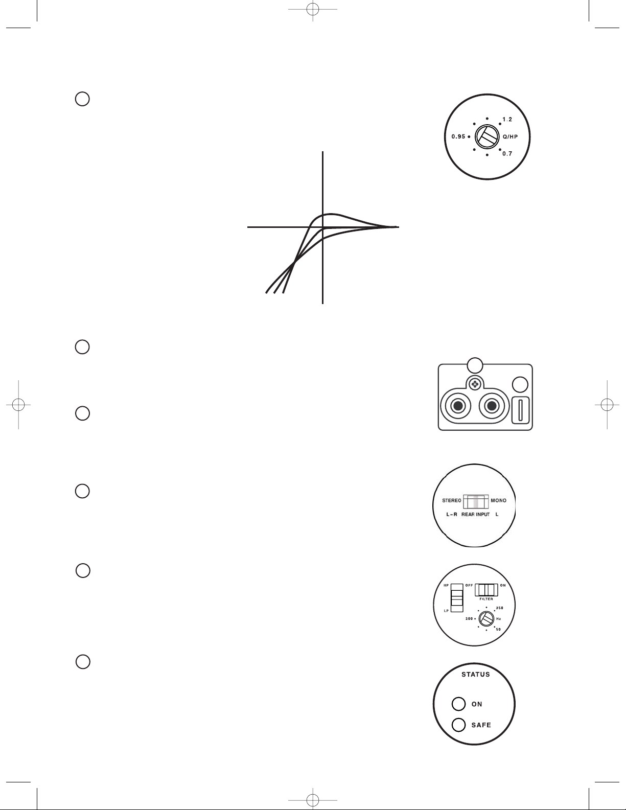
“Q” Control
“Q” Control is active when the highpass crossover is engaged and is centered
on the selected crossover point. The range of operation is 0.7–1.2.
REAR RCA Inputs
RCA cables marked “REAR” from head unit or other line level device should be
connected here. Use both inputs (L & R) for stereo.
REAR Remote Input
This remote input is parallel to the FRONT remote input and does not need to
be connected for the amplifier to operate. Use either remote input to turn the
amplifier on. Do not connect 12V accessories to this input.
REAR Input Switch
In the left position, the L & R inputs go to the REAR L & R channels of the amplifier. In the right (MONO) position, the inputs are summed. Use this setting when
the REAR channels are used with a subwoofer.
REAR Crossover Controls
To use highpass 12dB/octave crossover, move left switch to upper position. To
use lowpass 12dB/octave crossover, move left switch to lower position. Highpass
and lowpass crossover frequencies are adjustable from 50Hz to 350Hz by rotary
control. Move filter switch to “ON” position to engage.
Status LED Indicators
GREEN indicates the normal operating condition; the amplifier is “ON.” GREEN
and RED together are normal when the amplifier is first turned “ON”; RED will
turn off after a few seconds. When both GREEN and RED remain on, the amplifier is in thermal shutdown condition. RED only indicates a fault condition, “SAFE.”
7
8
6
7
8
10
11
9
GT-40_manual 4/10/03 4:17 PM Page 5
+1.6dB
0dB
-3dB
1.2.95.707
dB
Q
(tuned crossover frequency)
t
6
Mechanical Functions
Recessed RCA Inputs
The input jacks are recessed into the body of the amplifier to provide clearance in tight mounting locations.
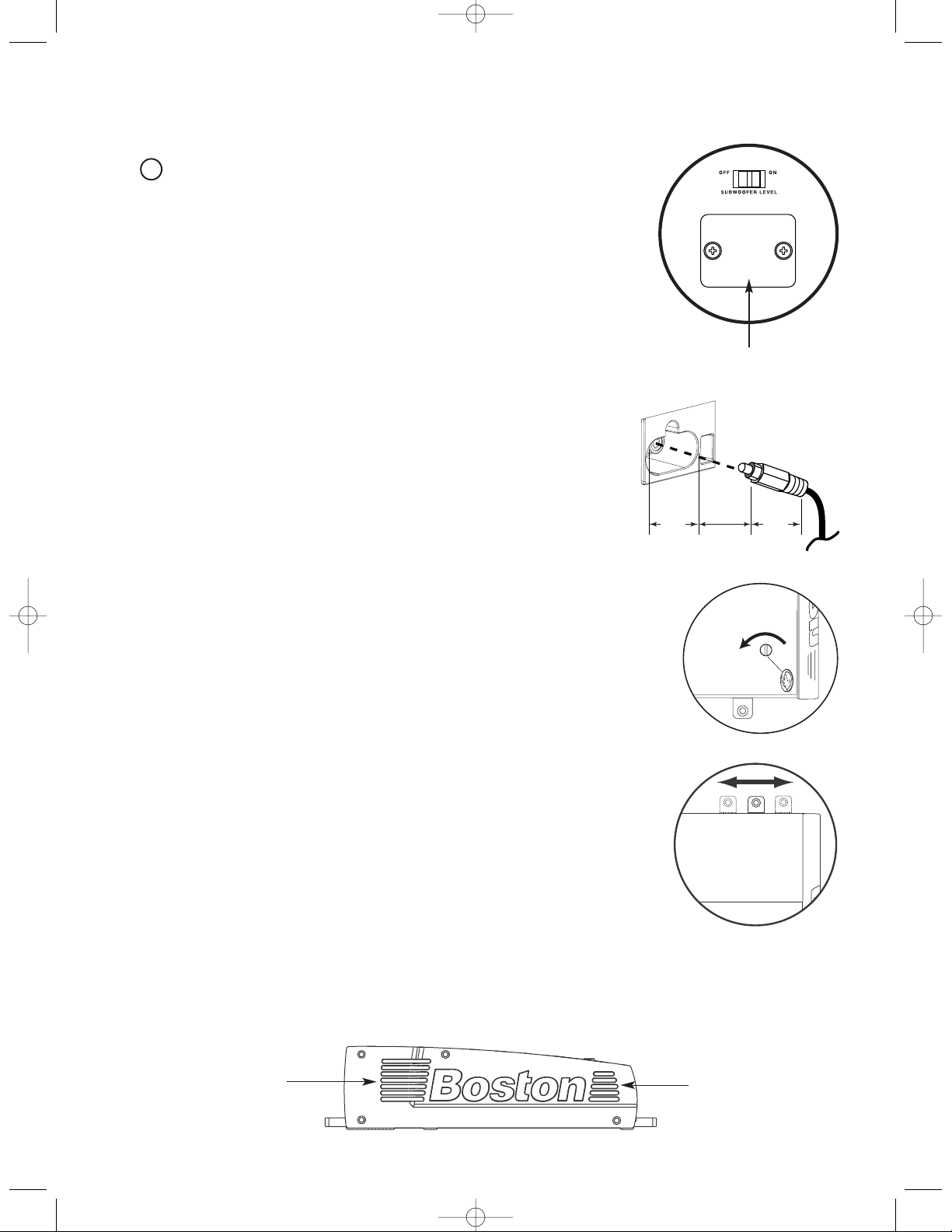
Control Cover Removal & Reinstallation
The cover panel is secured with two (2) captive coin-slotted screws. Coin-slotted
screws allow a coin edge to be used as a screwdriver to remove the panel.
Multi-position Mounting Feet
The mounting feet are designed to slide in both directions to clear installation
obstructions on the mounting surface.
WARNING! Before driving the mounting screws through any surface, be sure
of what is behind that surface. Check for the gas tank, brake lines, and any vehicle wiring harness.
Vents (Side & Rear)
The cooling vents must be kept clear of obstructions once the amplifier is installed. Failure to do this could
lead to premature thermal shutdown or amplifier failure.
upper side vent
lower side vent
Control Functions (cont.)
Subwoofer Level Control Port
Switch should be set to “OFF” when control circuit is not installed,
(see optional “subwoofer level control” owner’s manual).
12
cover panel
GT-40_manual 4/10/03 4:17 PM Page 6
1 inch 1 inch
 Loading...