

Page 1
OPERATION and MAINTENANCE MANUAL
MANUAL DE OPERACIÓN Y DE MANTENIMIENTO
MANUEL D’INSTRUCTIONS ET D’ENTRETIEN
HP118K
23 GAUGE HEADLESS PINNER
INSTALADORA DE PASADORES SIN CABEZA CALIBRE 23
PISTOLET À GOUPILLES SANS TÊTE CALIBRE 23
171245REVC 01/09
BEFORE OPERATING THIS TOOL, ALL OPERATORS SHOULD STUDY THIS MANUAL TO
UNDERSTAND AND FOLLOW THE SAFETY WARNINGS AND INSTRUCTIONS. KEEP THESE
INSTRUCTIONS WITH THE TOOL FOR FUTURE REFERENCE. IF YOU HAVE ANY QUESTIONS,
CONTACT YOUR BOSTITCH REPRESENTATIVE OR DISTRIBUTOR.
ANTES DE OPERAR ESTA HERRAMIENTA, TODOS LOS OPERADORES DEBERÁN ESTUDIAR
ESTE MANUAL PARA PODER COMPRENDER Y SEGUIR LAS ADVERTENCIAS SOBRE
SEGURIDAD Y LAS INSTRUCCIONES. MANTENGA ESTAS INSTRUCCIONES CON LA
HERRAMIENTA PARA FUTURA REFERENCIA, SI TIENE ALGUNA DUDA, COMUNÍQUESE CON
SU REPRESENTANTE DE BOSTITCH O CON SU DISTRIBUIDOR.
LIRE ATTENTIVEMENT LE PRÉSENT MANUEL AVANT D’UTILISER L’APPAREIL. PRÉTER UNE
ATTENTION TOUTE PARTICULIÈRE AUX CONSIGNES DE SÉCURITÉ ET AUX
AVERTISSEMENTS. GARDER CE MANUEL AVEC L’OUTIL POUR FUTUR RÉFÉRENCE. SI VOUS
AVEZ DES QUESTIONS, CONTACTEZ VOTRE REPRÉSENTANT OU VOTRE
CONCESSIONNAIRE BOSTITCH.
STANLEY FASTENING SYSTEMS L.P.
Page 2

-2-
INTRODUCTION
T
he BOSTITCH HP118K series pinners are precision-built tools, designed for high speed, high volume
fastening. This tool will deliver efficient, dependable service when used correctly and with care. As with any
f
ine power tool, for best performance the manufacturer’s instructions must be followed. Please study this
manual before operating the tool and understand the safety warnings and cautions. The instructions on
i
nstallation, operation and maintenance should be read carefully, and the manuals kept for reference. NOTE:
Additional safety measures may be required because of your particular application of the tool. Contact your
BOSTITCH representative or distributor with any questions concerning the tool and its use. BOSTITCH, Inc.,
E
ast Greenwich, Rhode Island 02818.
INDEX
S
afety Instructions . . . . . . . . . . . . . . . . . . . . . . . . . . . . . . . . . . . . . . . . . . . . . . . . . . . . 3
Tool Specifications . . . . . . . . . . . . . . . . . . . . . . . . . . . . . . . . . . . . . . . . . . . . . . . . . . . 4
A
ir Supply and Connections . . . . . . . . . . . . . . . . . . . . . . . . . . . . . . . . . . . . . . . . . . . . 5
Lubrication . . . . . . . . . . . . . . . . . . . . . . . . . . . . . . . . . . . . . . . . . . . . . . . . . . . . . . . . . 5
Loading the Tool . . . . . . . . . . . . . . . . . . . . . . . . . . . . . . . . . . . . . . . . . . . . . . . . . . . . . 6
Tool Operation . . . . . . . . . . . . . . . . . . . . . . . . . . . . . . . . . . . . . . . . . . . . . . . . . . . . . . . 7
Using the Belt Hook . . . . . . . . . . . . . . . . . . . . . . . . . . . . . . . . . . . . . . . . . . . . . . . . . 8-9
Fastner Jam Clearing . . . . . . . . . . . . . . . . . . . . . . . . . . . . . . . . . . . . . . . . . . . . . . . . . 10
Power Adjustment Valve . . . . . . . . . . . . . . . . . . . . . . . . . . . . . . . . . . . . . . . . . . . . . . . 10
Tool Operation Check . . . . . . . . . . . . . . . . . . . . . . . . . . . . . . . . . . . . . . . . . . . . . . . . . 11
Trouble Shooting . . . . . . . . . . . . . . . . . . . . . . . . . . . . . . . . . . . . . . . . . . . . . . . . . . . 12
Maintaining the Pneumatic Tool . . . . . . . . . . . . . . . . . . . . . . . . . . . . . . . . . . . . . . . . 13
Accessories . . . . . . . . . . . . . . . . . . . . . . . . . . . . . . . . . . . . . . . . . . . . . . . . . . . . . . . . 13
NOTE:
BOSTITCH tools have been engineered to provide excellent customer satisfaction and are designed to achieve
maximum performance when used with precision BOSTITCH fasteners engineered to the same exacting
standards. BOSTITCH cannot assume responsibility for product performance if our tools are used with
fasteners or accessories not meeting the specific requirements established for genuine BOSTITCH nails,
staples and accessories.
LIMITED WARRANTY — U.S. and Canada Only
Effective December 1, 2005 Bostitch, L.P. warrants to the original retail purchaser that the product purchased is free
from defects in material and workmanship, and agrees to repair or replace, at Bostitch’s option, any defective Bostitch
branded pneumatic stapler or nailer for a period of seven (7) years from date of purchase (one (1) year from the date
of purchasefor compressors and tools used in production applications).Warranty is not transferable. Proof of purchase
date required.This warranty covers only damage resulting from defects in material or workmanship; it does not cover
conditions or malfunctions resulting from normal wear, neglect, abuse, accident or repairs attempted or made by other
than our national repair center or authorized warranty service centers. Driver blades, bumpers, o-rings, pistons and
piston rings are considered normally wearing parts. For optimal performance of your Bostitch tool always use genuine
Bostitch fasteners and replacement parts.
THIS WARRANTY IS IN LIEU OF ALL OTHER WARRANTIES, EXPRESS OR IMPLIED, INCLUDING BUT NOT
LIMITED TO THE IMPLIED WARRANTIES OF MERCHANTABILITY OR FITNESS FOR A PARTICULAR
PURPOSE.BOSTITCH SHALL NOT BE LIABLE FOR ANY INCIDENTAL OR CONSEQUENTIAL DAMAGES.
Some states and countries do not allow limitations on how long an implied warranty lasts, or the exclusion or limitation
of incidental or consequential damages, so the above limitations or exclusions may not apply to you. This warranty
gives youspecific legal rights,and you may also have other rights which vary from state to state and countryto country.
To obtain warranty service in the U.S. return the product, together with proof of purchase, to the U.S. Bostitch National
or Regional Independent Authorized Warranty Service Center. In the U.S. you may call us at 1-800-556-6696 or visit
www.BOSTITCH.com for the location most convenient for you. In Canada please call us at 800-567-7705 or visit
www.BOSTITCH.com
Page 3
SAFETY INSTRUCTIONS
EYE PROTECTION which conforms to ANSI specifications and provides protection against
flying particles both from the FRONT and SIDE should ALWAYS be worn by the operator and
o
thers in the work area when connecting to air supply, loading, operating or servicing this
t
ool. Eye protection is required to guard against flying fasteners and debris, which could
cause severe eye injury.
T
he employer and/or user must ensure that proper eye protection is worn. Eye protection
e
quipment must conform to the requirements of the American National Standards Institute,
ANSI Z87.1 and provide both frontal and side protection. NOTE: Non-side shielded
spectacles and face shields alone do not provide adequate protection.
CAUTION:
Additional Safety Protection will be required in some environments. For example,
the working area may include exposure to noise level which can lead to hearing damage.
The employer and user must ensure that any necessary hearing protection is provided and
u
sed by the operator and others in the work area. Some environments will require the use
o
f head protection equipment.When required, the employer and user must ensure that head
protection conforming to ANSI Z89.1 is used.
AIR SUPPLY AND CONNECTIONS
Do not use oxygen, combustible gases, or bottled gases as a power source for this tool as
tool may explode, possibly causing injury.
Do not use supply sources which can potentially exceed 200 P.S.I.G. as tool may burst,
possibly causing injury.
The connector on the tool must not hold pressure when air supply is disconnected. If a
wrong fitting is used, the tool can remain charged with air after disconnecting and thus will
be able to drive a fastener even after the air line is disconnected possibly causing injury.
Do not pull trigger while connected to the air supply as the tool may cycle, possibly causing
injury.
Always disconnect air supply: 1.) Before making adjustments; 2.) When servicing the tool;
3.) When clearing a jam; 4.) When tool is not in use; 5.) When moving to a different work area,
as accidental actuation may occur, possibly causing injury; 6.) Before placing tool on any
surface, hanging tool on belt, or otherwise temporarily supsending use of the tool.
LOADING TOOL
When loading tool: 1.) Never place a hand or any part of body in fastener discharge area of
tool; 2.) Never point tool at anyone; 3.) Do not pull the secondary trigger as accidental
actuation may occury, possibly casuing injury.
OPERATION
Always handle the tool with care: 1.) Never engage in horseplay; 2.) Never pull or grasp the
secondary trigger unless nose is directed toward the work; 3.) Keep others a safe distance
from the tool while tool is in operation as accidental actuation may occur, possibly causing
injury.
The operator must not hold the secondary trigger pulled except during fastening operation
as serious injury could result if the trigger accidentally contacts someone or something,
causing the tool to cycle.
Keep hands and body away from the discharge area of the tool.
Check operation of the secondary trigger mechanism frequently. Do not use the tool if the
secondary trigger is not working correctly as accidental driving of a fastener may result. Do
not interfere with the proper operation of the secondary trigger mechanism.
Never inadvertently pull or grasp the secondary trigger when moving about, changing work
location, when holstering or hanging tool, or when preparing work surface for fastening
operation.
Do not drive fasteners on top of other fasteners or with the tool at an overly steep angle as
this may cause deflection of fasteners which could cause injury.
Do not drive fasteners close to the edge of the work piece as the wood may split, allowing
the fastener to be deflected possibly causing injury.
This nailer produces SPARKS during operation. NEVER use the nailer near flammable
substances, gases or vapors including lacquer, paint, benzine, thinner, gasoline, adhesives,
mastics, glues or any other material that is -- or the vapors, fumes or byproducts of which are -flammable, combustible or explosive. Using the nailer in any such environment could cause an
EXPLOSION resulting in personal injury or death to user and bystanders.
-3-
Page 4

-4-
TOOL SPECIFICATIONS
All screws and nuts are metric.
FASTENER SPECIFICATIONS:
TOOL AIR FITTING:
This tool uses a free-flow connector plug, 1/4” N.P.T.The minimum inside diameter should be .200” (5mm).
The fitting must be capable of discharging tool air pressure when disconnected from the air supply.
OPERATING PRESSURE:
70 to 100 p.s.i. (4.9 to 7.1 kg/cm2). Select the operating pressure within this range for best fastener
performance. DO NOT EXCEED THIS RECOMMENDED OPERATING PRESSURE.
AIR CONSUMPTION:
Model HP118K requires 1.86 cubic feet per minute (.053 cubic meters) of free air to operate at the rate of 100
fasteners per minute, at 80 p.s.i. (5.6kg/cm2). Take the actual rate at which the tool will be run to determine the
amount of air required. For instance, if your fastener usage averages 50 fasteners per minute, you need 50%
of the tool's c.f.m. of free air which is required for running at 100 fasteners per minute.
M
ODEL LENGTH HEIGHT WIDTH WEIGHT
HP118K 9.06” (230.1mm) 7.81” (198.4mm) 1.60” (40.6mm) 2.17lb. (.984kg.)
MODEL HEADLESS GAUGE FASTENER RANGE MAGAZINE
PIN SERIES CAPACITY
HP118K PT-23XX 23 3/8”- 1-3/16” (9-30mm) 200 PINS
MAINTAINING THE TOOL
W
hen working on air tools note the warnings in this manual and use extra care when
e
valuating problem tools.
Page 5

-5-
AIR SUPPLY AND CONNECTIONS
Do not use oxygen, combustible gases, or bottled gases as a power source for this tool as
tool may explode, possibly causing injury.
FITTINGS:
I
nstall a male plug on the tool which is free flowing and which will release air pressure from the tool when
disconnected from the supply source.
HOSES:
Air hoses should have a minimum of 150 p.s.i. (10.6 kg/cm2) working pressure rating or 150 percent of the
m
aximum pressure that could be produced in the air system. The supply hose should contain a fitting that will
provide “quick disconnecting” from the male plug on the tool.
SUPPLY SOURCE:
Use only clean regulated compressed air as a power source for this tool. NEVER USE OXYGEN, COMBUSTIBLE
G
ASES, OR BOTTLED GASES, AS A POWER SOURCE FOR THIS TOOL AS TOOL MAY EXPLODE.
REGULATOR:
A pressure regulator with an operating pressure of 0 - 125 p.s.i. (0 - 8.79 KG/CM2) is required to control the
operating pressure for safe operation of this tool. Do not connect this tool to air pressure which can potentially
exceed 200 p.s.i. (14 KG/CM
2
) as tool may fracture or burst, possibly causing injury.
OPERATING PRESSURE:
Do not exceed recommended maximum operating pressure as tool wear will be greatly increased. The air
supply must be capable of maintaining the operating pressure at the tool. Pressure drops in the air supply can
reduce the tool’s driving power. Refer to “TOOL SPECIFICATIONS” for setting the correct operating pressure
for the tool.
FILTER:
Dirt and water in the air supply are major causes of wear in pneumatic tools. A filter will help to get the best
performance and minimum wear from the tool. The filter must have adequate flow capacity for the specific
installation. The filter has to be kept clean to be effective in providing clean compressed air to the tool. Consult
the manufacturer’s instructions on proper maintenance of your filter. A dirty and clogged filter will cause a
pressure drop which will reduce the tool’s performance.
LUBRICATION
Frequent, but not excessive, lubrication is required for best performance. Oil added through the air line
connection will lubricate the internal parts. Use BOSTITCH AirTool Lubricant, Mobil Velocite #10, or equivalent.
Do not use detergent oil or additives as these lubricants will cause accelerated wear to the seals and bumpers
in the tool, resulting in poor tool performance and frequent tool maintenance.
If no airline lubricator is used, add oil during use into the air fitting on the tool once or twice a day. Only a few
drops of oil at a time is necessary. Too much oil will only collect inside the tool and will be noticeable in the
exhaust cycle.
COLD WEATHER OPERATION:
For cold weather operation, near and below freezing, the moisture in the air line may freeze and prevent tool
operation. We recommend the use of BOSTITCH WINTER FORMULA air tool lubricant or permanent
antifreeze (ethylene glycol) as a cold weather lubricant.
CAUTION: Do not store tools in a cold weather environment to prevent frost or ice formation on the
tools operating valves and mechanisms that could cause tool failure.
NOTE:Some commercial air line drying liquids are harmful to “O”-rings and seals – do not use these
low temperature air dryers without checking compatibility.
Page 6
LOADING THE HP118K
E
YE PROTECTIONwhich conforms to ANSI specifications and provides protection against
f
lying particles both from the FRONT and SIDE should ALWAYS be worn by the operator and
others in the work area when connecting to air supply, loading, operating or servicing this
tool. Eye protection is required to guard against flying fasteners and debris, which could
cause severe eye injury.
The employer and/or user must ensure that proper eye protection is worn. Eye protection
equipment must conform to the requirements of the American National Standards Institute,
ANSI Z87.1 and provide both frontal and side protection. NOTE: Non-side shielded
s
pectacles and face shields alone do not provide adequate protection.
TO PREVENT ACCIDENTAL INJURIES:
•
Never place a hand or any other part of the body in nail discharge area of tool while
the air supply is connected.
• Never point the tool at anyone else.
• Never engage in horseplay.
•
Never pull or grasp the secondary trigger unless nose is directed at the work.
• Always handle the tool with care.
•
Do not pull either of the two triggers while loading the tool.
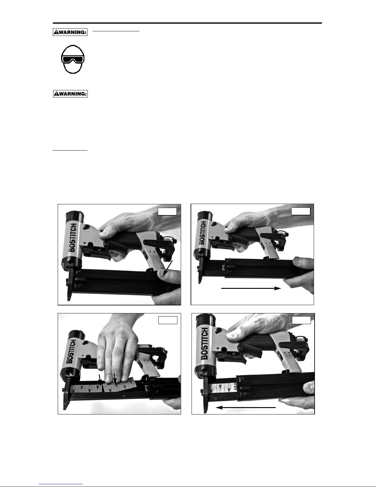
LOADING:
1. Depress the spring loaded lever as shown in Fig.1.
2. Pull sliding portion of magazine back as shown in Fig.2
3. Load the stick of pins as shown in Fig.3 with the arrow pattern pointing down as shown. If pins have
black dots instead of arrows, the dots should be positioned up.
4. Close magazine as shown in Fig.4 until it latches in the forward position. The tool is now ready for use.
-6-
Fig.1
Fig.2
Fig.3 Fig.4
Page 7
-7-
TOOL OPERATION
E
YE PROTECTIONwhich conforms to ANSI specifications and provides protection against
flying particles both from the FRONT and SIDE should ALWAYS be worn by the operator and
others in the work area when connecting to air supply, loading, operating or servicing this
tool. Eye protection is required to guard against flying fasteners and debris, which could
c
ause severe eye injury.
T
he employer and/or user must ensure that proper eye protection is worn. Eye protection
e
quipment must conform to the requirements of the American National Standards Institute,
ANSI Z87.1 and provide both frontal and side protection. NOTE: Non-side shielded
spectacles and face shields alone do not provide adequate protection.
BEFORE HANDLING OR OPERATING THIS TOOL:
I
. READ AND UNDERSTAND THE WARNINGS CONTAINED IN THIS MANUAL.
B
OSTITCH offers one type of operation for the HP118K series tools.
T
RIGGER OPERATION WITH SECONDARY TRIGGER
OPERATION
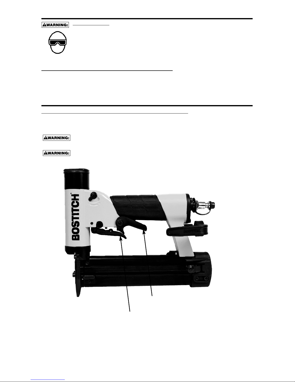
TRIGGER OPERATION WITH A SECONDARY TRIGGER:
The tool will actuate each time the trigger under the valve is pulled until the secondary trigger under the
hand grip is released. This trigger operated tool is operated by first pulling or grasping the secondary trigger
under the hand grip, followed by pulling the trigger under the valve as shown.
Never inadvertently pull or grasp the secondary trigger when moving about, changing work
location, when holstering or hanging tool, or when preparing work surface for fastening
operation.
The operator must not hold the secondary trigger pulled except during fastening operation
as serious injury could result if the trigger accidentally contacts someone or something,
causing the tool to cycle.
Pull or grasp this secondary trigger first
Pull this trigger second
Page 8
-8-
USING THE BELT HOOK
A
lways disconnect tool from air supply when making adjustments or servicing.
The operator must not hold the secondary trigger pulled except during fastening operation
as serious injury could result if the trigger accidentally contacts someone or something,
c
ausing the tool to cycle.
Never inadvertently pull or grasp the secondary trigger when moving about, changing work
location, when holstering or hanging tool, or when preparing work surface for fastening
o
peration.
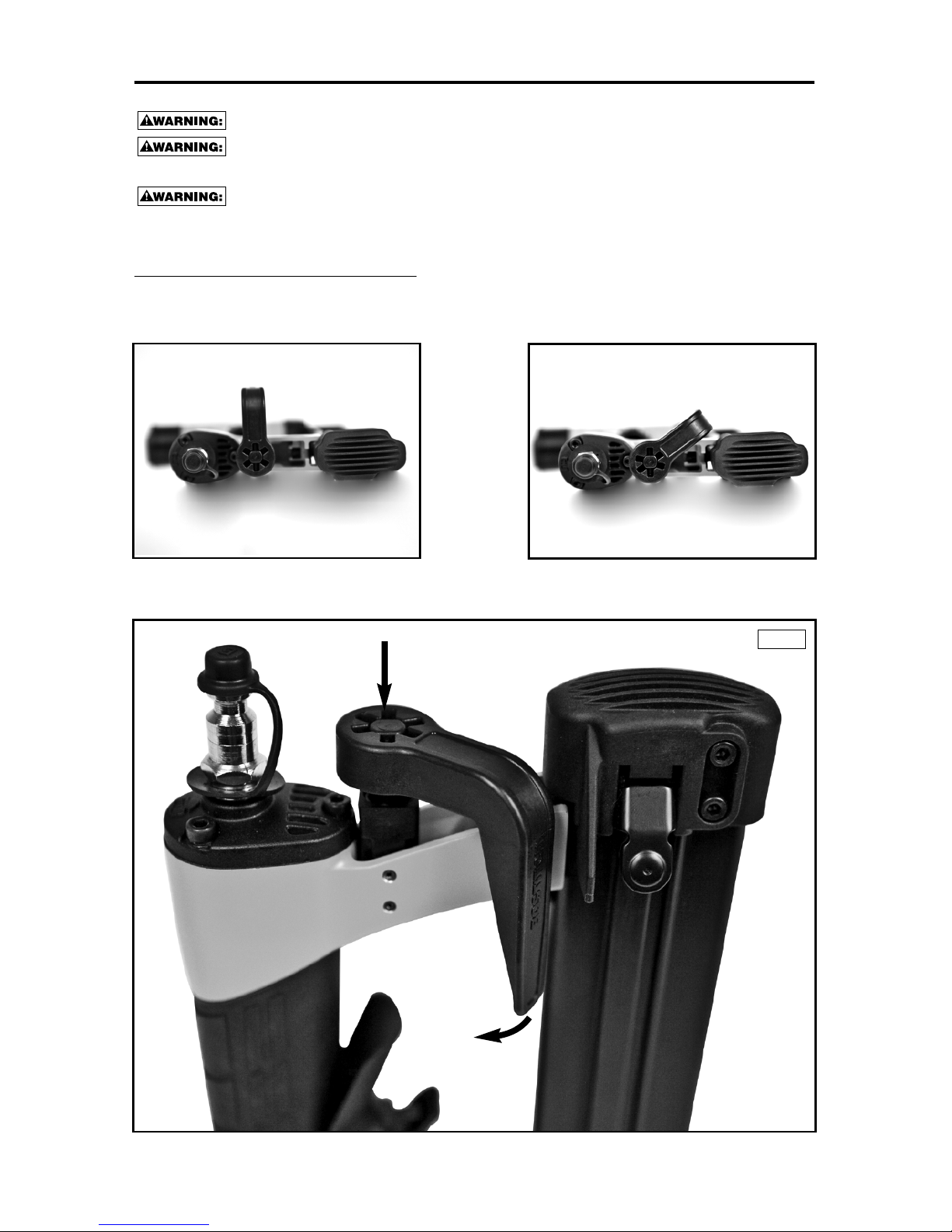
OPERATION AND ORIENTATION:
The belt hook can be adjusted to two orientations; open or closed. The open orientation allows the user to
h
ang the tool from a belt (or equivalent) whereas the closed position allows the user to place the tool back
inside the case. The following depicts these two orientations:
In order to adjust the tool to either of these orientations, simply push down on the belt hook, rotate clockwise
or counter-clockwise and release as shown in FIG 1.
1. PUSH DOWN ON BELT HOOK
2. ROTATE
3. RELEASE
Fig.1
OPEN
CLOSED
Page 9
-9-
USING THE BELT HOOK
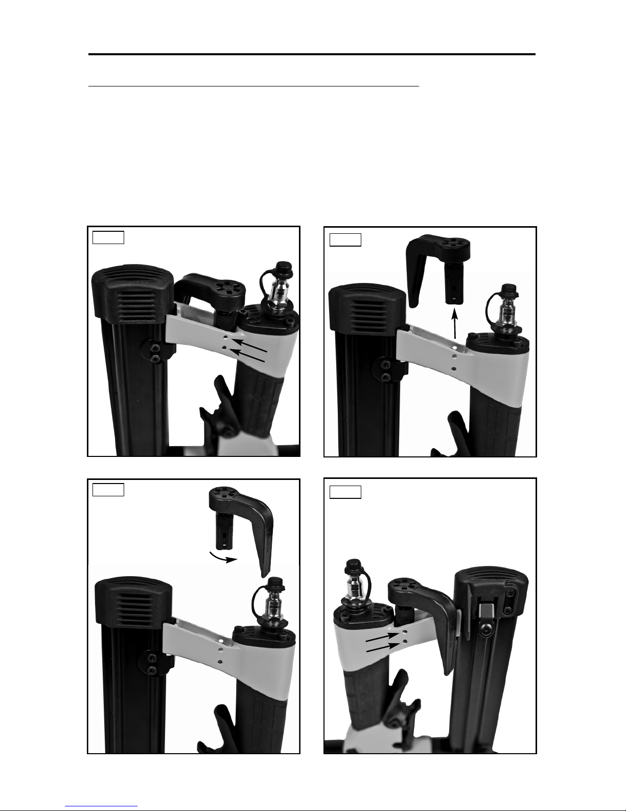
ADJUSTING THE BELT HOOK FOR A LEFT-HANDED USER
In order to adjust the tool for a left-handed user, simply remove the belt hook assembly, rotate it 180° and
r
e-assemble. The following depicts exactly how this is done:
1
. Remove both spring pins that attach the belt hook assembly to the frame as shown in Fig 1.
2. Slide the belt hook assembly away from the rear of the tool as shown in Fig 2.
3. Rotate the belt hook assembly 180° as shown in Fig 3.
4. Align the holes in the frame with the holes in the mount. Then, re-assemble both spring pins
a
s shown in Fig 4.
Fig.1
Fig.2
Fig.3
Fig.4
Page 10
-10-
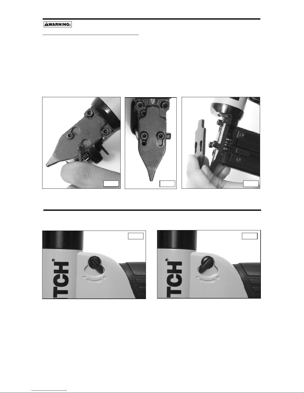
FASTENER JAM CLEARING
ALWAYS DISCONNECT AIR SUPPLY BEFORE CLEARING A JAMMED FASTENER.
TO CLEAR A JAMMED FASTENER:
1. Release the magazine and pull it back to stop pin feeding.
2. Loosen the two screws as shown in Fig.1 by one full turn.
3. Slide cover down until the two large clearance holes line up with the two screw heads as shown in Fig.2.
4. Pull the cover away from nose as shown in Fig.3.
5. Remove the jammed fastener.
6. Re-install cover, slide it up, tighten the two screws and close magazine.
7. Reconnect air hose.
Fig.3Fig.2
Fig.1
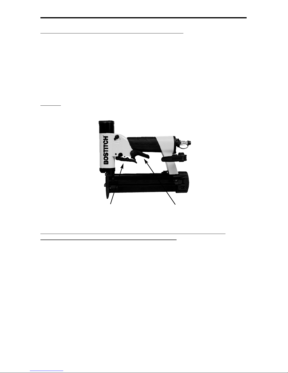
POWER ADJUSTMENT
For maximum power: rotate lever to right as shown in Fig.1
To reduce power: rotate lever to left as shown in Fig.2
Fig.1
Fig.2
MAXIMUM POWER SETTING
MINIMUM POWER SETTING
Page 11
-11-
TOOL OPERATION CHECK:
CAUTION: Remove all fasteners from tool before performing tool operation check.
TRIGGER OPERATION WITH A SECONDARY TRIGGER:
The primary trigger is located under the trigger valve. It can actuate the tool only if the secondary trigger has
a
lready been pulled.
The secondary trigger is located under the handle. The secondary trigger prevents the primary trigger from
a
ctuating the tool if the secondary trigger has not been pulled first.
P
lace the nose of the tool against a work piece for all of the following operation checks.
A. With hand on rear end of the handle, further back away from the secondary trigger, and not squeezing
the secondary trigger, use finger to pull the primary trigger.
T
HE TOOL MUST NOT CYCLE.
B
. With hand on handle, and squeezing the secondary trigger, use finger to pull the primary trigger.
THE TOOL MUST CYCLE.
CAUTION:
WHILE THE SECONDARY TRIGGER REMAINS SQUEEZED,THE TOOL WILL CYCLE
EACH TIME THE PRIMARY TRIGGER IS PULLED!
IN ADDITION TO THE OTHER WARNINGS CONTAINED IN THIS MANUAL
OBSERVE THE FOLLOWING FOR SAFE OPERATION
• Use the BOSTITCH pneumatic tool only for the purpose for which it was designed.
• Never use this tool in a manner that could cause a fastener to be directed toward the user
or others in the work area.
• Do not use the tool as a hammer.
• Always carry the tool by the handle with hand off both triggers. Never carry the tool by the air hose.
• Do not alter or modify this tool from the original design or function without approval
from BOSTITCH
• Always be aware that misuse and improper handling of this tool can cause injury to
yourself and others.
• Never clamp or tape the trigger or secondary trigger in an actuated position.
• Never leave a tool unattended with the air hose attached.
• Do not operate this tool if it does not contain a legible WARNING LABEL.
• Do not continue to use a tool that leaks air or does not function properly. Notify your
nearest BOSTITCH representative if your tool continues to experience functional problems.
SECONDARY TRIGGER
PRIMARY TRIGGER
Page 12

-12-
TROUBLE SHOOTING
PROBLEM CAUSE CORRECTION
Trigger valve housing leaks air O-ring cut or cracked . . . . . . . . . . . . . . . . . .Replace O-ring
Trigger valve stem leaks air O-ring/seals cut or cracked . . . . . . . . . . . . .Replace trigger valve assembly
F
rame/nose leaks air Loose nose screws . . . . . . . . . . . . . . . . . . .Tighten and recheck
O
-ring or Gasket is cut or cracked . . . . . . .Replace O-ring or gasket
B
umper cracked/worn . . . . . . . . . . . . . . . . .Replace bumper
F
rame/cap leaks air Damaged gasket or seal . . . . . . . . . . . . . . .Replace gasket or seal
Cracked/worn head valve bumper . . . . . . . .Replace bumper
Loose cap screws . . . . . . . . . . . . . . . . . . . .Tighten and recheck
Failure to cycle Air supply restriction . . . . . . . . . . . . . . . . . .Check air supply equipment
Tool dry, lack of lubrication . . . . . . . . . . . . .Use BOSTITCH Air Tool Lubricant
W
orn head valve O-rings . . . . . . . . . . . . . . .Replace O-rings
B
roken cylinder cap spring . . . . . . . . . . . . .Replace cylinder cap spring
H
ead valve stuck in cap . . . . . . . . . . . . . . . .Disassemble/Check/Lubricate
Lack of power; slow to cycle Tool dry, lacks lubrication . . . . . . . . . . . . . .Use BOSTITCH Air Tool Lubricant
Broken cylinder cap spring . . . . . . . . . . . . .Replace cap spring
O-rings/seals cut or cracked . . . . . . . . . . . .Replace O-rings/seals
Exhaust blocked . . . . . . . . . . . . . . . . . . . . .Check bumper, head valve spring, muffler
T
rigger assembly worn/leaks . . . . . . . . . . . .Replace trigger assembly
D
irt/tar build up on driver . . . . . . . . . . . . . . .Disassemble nose/driver to clean
Cylinder sleeve not seated correctly
on bottom bumper . . . . . . . . . . . . . . . . . . . .Disassemble to correct
Head valve dry . . . . . . . . . . . . . . . . . . . . . . .Disassemble/lubricate
aAir pressure too low . . . . . . . . . . . . . . . . . .Check air supply equipment
Skipping fasteners; Worn bumper . . . . . . . . . . . . . . . . . . . . . . . .Replace bumper
intermittent feed Tar/dirt in driver channel . . . . . . . . . . . . . . .Disassemble and clean nose and driver
Air restriction/inadequate air flow through
quick disconnect socket and plug . . . . . . . .Replace quick disconnect fittings
Worn piston O-ring . . . . . . . . . . . . . . . . . . .Replace O-ring, check driver
Tool dry, lacks lubrication . . . . . . . . . . . . . .Use BOSTITCH Air Tool Lubricant
Damaged pusher spring . . . . . . . . . . . . . . .Replace spring
Low air pressure . . . . . . . . . . . . . . . . . . . . .Check air supply system to tool
Loose magazine nose screws . . . . . . . . . . .Tighten all screws
Fasteners too short for tool . . . . . . . . . . . . .Use only recommended fasteners
Bent fasteners . . . . . . . . . . . . . . . . . . . . . . .Discontinue using these fasteners
Wrong size fasteners . . . . . . . . . . . . . . . . . .Use only recommended fasteners
Leaking head cap gasket . . . . . . . . . . . . . .Tighten screws/replace gasket
Trigger valve O-ring cut/worn . . . . . . . . . . .Replace O-ring
Broken/chipped driver . . . . . . . . . . . . . . . . .Replace driver (check piston O-ring)
Dry/dirty magazine . . . . . . . . . . . . . . . . . . .Clean/lubricate use BOSTITH Air Tool
. . . . . . . . . . . . . . . . . . . . . . . . . . . . . . . . . . .Lubricant
Worn magazine . . . . . . . . . . . . . . . . . . . . . .Replace magazine
Fasteners jam in tool Driver channel worn . . . . . . . . . . . . . . . . . .Replace nose/check door
Wrong size fasteners . . . . . . . . . . . . . . . . . .Use only recommended fasteners
Bent fasteners . . . . . . . . . . . . . . . . . . . . . . .Discontinue using these fasteners
Loose magazine/nose screws . . . . . . . . . . .Tighten all screws
Broken/chipped driver . . . . . . . . . . . . . . . . .Replace driver
Page 13

-13-
MAINTAINING THE PNEUMATIC TOOL
When working on air tools, note the warnings in this manual and use extra care evaluating
p
roblem tools.
REPLACEMENT PARTS:
B
OSTITCH replacement parts are recommended. Do not use modified parts or parts which will not give
equivalent performance to the original equipment.
ASSEMBLY PROCEDURE FOR SEALS:
When repairing a tool, make sure the internal parts are clean and lubricated. Use Parker “O”-LUBE or
equivalent on all “O”-rings. Coat each “O”-ring with “O”-LUBE before assembling. Use a small amount of oil
o
n all moving surfaces and pivots. After reassembly add a few drops of BOSTITCH Air Tool Lubricant
through the air line fitting before testing.
AIR SUPPLY-PRESSURE AND VOLUME:
A
ir volume is as important as air pressure. The air volume supplied to the tool may be inadequate because of
undersize fittings and hoses, or from the effects of dirt and water in the system. Restricted air flow will
prevent the tool from receiving an adequate volume of air, even though the pressure reading is high. The
results will be slow operation, misfeeds or reduced driving power. Before evaluating tool problems for these
symptoms, trace the air supply from the tool to the supply source for restrictive connectors, swivel fittings,
low points containing water and anything else that would prevent full volume flow of air to the tool.
TRIGGER VALVE REMOVAL:
1. Remove the two trigger valve pins as well as the secondary trigger and it’s spring.
2. Remove the trigger valve (with primary trigger still attached to it).
ACCESSORIES AVAILABLE
BC601 4 oz. BOSTITCH Air -Tool Lubricant
BC602 1 pint BOSTITCH Air -Tool Lubricant
BC603 1 pint BOSTITCH “Winter-Formula” Air-Tool Lubricant
BC604 1 quart BOSTITCH Air -Tool Lubricant
100679 O-Ring Lube (1lb. can)
851325 Locite Grade 271 (.02 oz.)
851385 Locite Grade 242 (.02 oz.)
Trigger
valve pin
Trigger valve and
primary trigger
Trigger
valve pin
Spring is located under
secondary trigger
Secondary trigger
Page 14

-14-
INTRODUCCIÓN
Las instaladoras de pasadores de BOSTITCH serie HP118K son herramientas construidas a precisión,
d
iseñadas para funcionar a alta velocidad y con alto volumen. Estas herramientas darán un servicio eficiente
y seguro, siempre y cuando sean utilizadas correctamente y con cuidado. Como con cualquier herramienta
automática de calidad, el mejor rendimiento se obtiene siguiendo las indicaciones del fabricante. Por favor,
e
studie este manual antes de operar esta herramienta y asegúrese de entender perfectamente las
advertencias y precauciones de seguridad. Las instrucciones sobre instalación, operación y mantenimiento se
d
eben leer cuidadosamente y el manual deberá conservarse como referencia. NOTA: Se pueden requerir
medidas adicionales de seguridad en relación con la operación particular que usted destina a la herramienta.
P
óngase en contacto con su representante o distribuidor de BOSTITCH en relación con cualquier pregunta o
duda relativa a esta herramienta y su uso. BOSTITCH, East Greenwich, Rhode Island 02818.
ÍNDICE
I
nstrucciones de seguridad . . . . . . . . . . . . . . . . . . . . . . . . . . . . . . . . . . . . . . . . . . . . 15
Especificaciones de la herramienta . . . . . . . . . . . . . . . . . . . . . . . . . . . . . . . . . . . . . 16
Suministro de aire y conexiones . . . . . . . . . . . . . . . . . . . . . . . . . . . . . . . . . . . . . . . . 17
Lubricación . . . . . . . . . . . . . . . . . . . . . . . . . . . . . . . . . . . . . . . . . . . . . . . . . . . . . . . . 17
Carga de la herramienta . . . . . . . . . . . . . . . . . . . . . . . . . . . . . . . . . . . . . . . . . . . . . 18
Funcionamiento de la herramienta . . . . . . . . . . . . . . . . . . . . . . . . . . . . . . . . . . . . . . 19
Uso del gancho de cinturón . . . . . . . . . . . . . . . . . . . . . . . . . . . . . . . . . . . . . . . . . 20-21
Eliminación de atascos de los pasadores . . . . . . . . . . . . . . . . . . . . . . . . . . . . . . . . . 22
Válvula de ajuste de potencia. . . . . . . . . . . . . . . . . . . . . . . . . . . . . . . . . . . . . . . . . . . 22
Revisión funcional de la herramienta . . . . . . . . . . . . . . . . . . . . . . . . . . . . . . . . . . . . . 23
Solución de problemas. . . . . . . . . . . . . . . . . . . . . . . . . . . . . . . . . . . . . . . . . . . . . . . 24
Mantenimiento de la herramienta neumática . . . . . . . . . . . . . . . . . . . . . . . . . . . . . . 25
Accesorios . . . . . . . . . . . . . . . . . . . . . . . . . . . . . . . . . . . . . . . . . . . . . . . . . . . . . . . . . 25
NOTA:
Las herramientas de BOSTITCH han sido fabricadas para proporcionar una excelente satisfacción al cliente y
están diseñadas para lograr el máximo rendimiento al ser utilizadas con sujetadores de precisión de BOSTITCH
que han sido fabricados a las mismas normas exactas. BOSTITCH no puede asumir responsabilidad por el
rendimiento de un producto si se utilizan nuestras herramientas con sujetadores o accesorios que no
cumplen con los requisitos específicos establecidos para clavos, grapas y accesorios auténticos de
BOSTITCH.
GARANTÍA LIMITADA — Sólo EE.UU. y Canadá
A partir del 1 de diciembre de 2005 Bostitch, L.P. garantiza al comprador del comerciante original que el producto
comprado está exento de defectos en material y fabricación, y se compromete a reparar o reemplazar, a opción de
Bostitch, cualquier engrapadorao clavadora neumática defectuosa de marca Bostitch por un período desiete(7) años
desde la fecha de compra (un (1) año de la fecha de compra en el caso de compresores y herramientas utilizadas en
aplicaciones de producción). La garantía no es transferible. Se requiere presentar evidencia de la fecha de compra.
Esta garantía solamente cubre daños resultantes de defectos en material o fabricación, y no cubre condiciones o
desperfectos resultantes del desgaste normal, negligencia, abuso, accidente o reparaciones intentadas o efectuadas
por terceros ajenosa nuestro centro nacional de reparaciones o a los centrosde servicio bajo garantía.Las aspas del
impulsor, topes, juntas tóricas, pistones y aros de pistones se consideran componentes de desgaste normal. Para
obtener el rendimiento óptimo de la herramienta Bostitch siempre use fijaciones y piezas de repuesto genuinas de
Bostitch.
ESTA GARANTÍA SUSTITUYE TODA OTRA GARANTÍA, EXPRESA O IMPLÍCITA, INCLUIDAS ENTRE OTRAS,
LAS GARANTÍAS IMPLÍCITAS DE COMERCIABILIDAD O IDONEIDAD PARA UN FIN PARTICULAR. BOSTITCH
NO SERÁ RESPONSABLE DE DAÑOS FORTUITOS O CONSECUENCIALES.
Algunos estados y países no permiten limitaciones a la duración de una garantía implícita ni la exclusión o limitación
de daños fortuitos o consecuenciales, de modo que las limitaciones o exclusiones anteriores pueden no corresponder
a su caso. Esta garantía le concede derechos legales específicos, y usted puede tener también otros derechos que
varían de un estado a otro y de un país a otro.
Para obtener servicio bajo garantía en los EE.UU. devuelva el producto, junto con el comprobante de compra, al
Centro de Servicio bajo Garantía Autorizado Independiente Nacional o Regional de Bostitch en los EE.UU.Dentro de
los EE.UU. usted puede llamarnos al 1-800-556-6696 o visitar www.BOSTITCH.com para ver la ubicación que más
le convenga. En Canadá llámenos al at 800-567-7705 o visite www.BOSTITCH.com.
Page 15

INSTRUCCIONES DE SEGURIDAD
Cuando el equipo está conectado al suministro de aire, tanto el operador como todas las
p
ersonas que se encuentren en el área de trabajo, SIEMPRE deben usar PROTECCIÓN
OCULAR que cumpla las especificaciones ANSI para resguardo contra partículas volantes
a
rrojadas desde el FRENTE o los LATERALES. Dicha protección ocular se requiere para
p
roteger contra residuos y remaches volantes, que podrían causar graves lesiones en los ojos.
E
l empleador y/o usuario debe asegurar que la debida protección para los ojos sea usada. El
e
quipo protector de los ojos debe cumplir con los requisitos del Instituto de Normas
Nacionales Americano (American National Standards Institute), ANSI Z87.1 y debe proveer
protección de frente y de los lados.NOTA: Las gafas de seguridad que no están protegidas de
los lados y las máscaras por sí solas no proveen la debida protección.
P
RECAUCIÓN: En algunos entornos será necesaria protección de seguridad adicional. Por
ejemplo, es posible que el área de trabajo incluya la exposición a niveles de ruido que pueden
d
añar el oído. El empleador y el usuario deben asegurarse de que cualquier
p
rotección necesaria para los oídos sea provista y utilizada por el operador y demás
personas en el área de trabajo. Algunos entornos requieren el uso de aparatos de
p
rotección para la cabeza. Cuando sea necesario, el empleador y el usuario deben
a
segurarse de que se utilice protección para la cabeza en conformidad con la norma ANSI Z89.1.
SUMINISTRO DE AIRE Y CONEXIONES
No utilice oxígeno ni gases combustibles o embotellados como fuente de suministro para esta
herramienta, ya que la herramienta puede estallar, posiblemente causando lesiones.
No utilice fuentes de suministro que potencialmente excedan las 14 Kg/cm
2
(13,8 bars) ya
que la herramienta puede estallar, posiblemente causando lesiones.
El conector de la herramienta no debe tener presión al desconectarse el suministro de aire.
Si se utiliza una conexión equivocada, la herramienta puede permanecer cargada con aire
después de ser desconectada y por lo tanto podrá impulsar un sujetador aún después de
que la línea de aire sea desconectada, posiblemente causando lesiones.
No accione el gatillo con el suministro de aire conectado, ya que la herramienta puede hacer
un ciclo y causar lesiones.
Siempre desconecte el suministro de aire: 1.) Antes de hacer ajustes; 2.) Al dar servicio a la
herramienta; 3.) Al despejar atascos; 4.) Cuando no esté en uso la herramienta; 5.) Al acudir
a otra área de trabajo porque puede activarse accidentalmente causando posibles lesiones;
6.) Antes de colocar la herramienta en una superficie, colgarla del cinturón o suspender
provisoriamente su uso.
AL CARGAR LA HERRAMIENTA
Al cargar la herramienta: 1.) Nunca ponga la mano ni ninguna parte del cuerpo en el área
de descarga de fijaciones de la herramienta; 2.) Nunca apunte la herramienta a ninguna
persona; 3.) No accione el gatillo secundario ya que la unidad puede activarse
accidentalmente causando posibles lesiones.
OPERACIÓN
Siempre maneje la herramienta con cuidado: 1.) Nunca participe en juegos rudos; 2.) Nunca
accione ni tome el gatillo secundario si la punta no está dirigida hacia la pieza de trabajo; 3.)
Mantenga a los demás a una distancia segura de la herramienta mientras esté en
funcionamiento porque puede activarse accidentalmente causando posibles lesiones.
El operador no debe mantener el gatillo secundario accionado salvo durante la aplicación de
fijaciones ya que podrían ocurrir lesiones graves si el gatillo hiciera contacto accidentalmente
con algo o alguien, ocasionando que la herramienta haga un ciclo.
Mantenga las manos y el cuerpo alejados del área de descarga de la herramienta.
Revise frecuentemente la operación del mecanismo del gatillo secundario. No use la
herramienta si el gatillo secundario no funciona correctamente ya que puede impulsarse
accidentalmente una fijación. No interfiera con el funcionamiento correcto del mecanismo del
gatillo secundario.
Nunca accione ni tome el gatillo secundario al moverse de un lado a otro, al cambiar de
posición, enfundar o colgar la herramienta ni al preparar la superficie de trabajo a fin de
realizar operaciones de fijación.
No meta los sujetadores encima de otros sujetadores o teniendo la herramienta demasiado
inclinada ya que esto podría causar que los sujetadores se desviaran, y a su vez causaran
lesiones.
No meta los sujetadores cerca del borde de la pieza de trabajo porque la madera podría
separarse, lo que permitiría que el sujetador se desviara y causara lesiones.
-15-
Page 16
-16-
ESPECIFICACIONES DE LA HERRAMIENTA
Todos los tornillos y tuercas son métricos.
ESPECIFICACIONES DE LAS FIJACIONES:
CONEXIÓN DE AIRE DE LA HERRAMIENTA:
Esta herramienta usa un enchufe macho de 1/4" N.P.T. El diámetro interior debe ser de 5mm (0,2") o mayor.
La conexión debe ser capaz de descargar la presión de aire de la herramienta cuando es desconectada del
suministro de aire.
PRESIÓN DE OPERACIÓN:
4,9 a 7,1 kg/cm2(4,8 a 6,9 bars). Seleccione la presión de operación dentro de este rango para el mejor
rendimiento. NO EXCEDA ESTA PRESIÓN DE OPERACIÓN RECOMENDADA.
CONSUMO DE AIRE:
El Modelo HP118K necesita 0,053 metros cúbicos (1,86 pies cúbicos por minuto) de aire libre para funcionar
a razón de 100 pasadores por minuto, a 5,6 kg/cm
2
(80 p.s.i.). Tome la velocidad real con la cual operará la
herramienta para determinar la cantidad de aire necesaria. Por ejemplo, si el uso de pasadores promedia 50
por minuto, necesita el 50% de los pies cúbicos por minuto de la herramienta para funcionar a razón de 100
por minuto.
MODELO LONGITUD ALTURA ANCHO PESO
HP118K 230,1 mm (9,06“) 198,4 mm (7,81“) 40,6 mm (1,60”) 0,98 kg (2,17 lb)
SIN CABEZAL
MODELO SERIE DE CALIBRE GAMA DE PASADORES CARTUCHO
PASADORES CAPACIDAD
HP118K PT-23XX 23 9-30mm (3/8”- 1-3/16”) 200 PASADORES
MANTENIMIENTO DE LA HERRAMIENTA
T
ome nota de las advertencias en este manual al trabajar con herramientas neumáticas y tenga
m
ayor cuidado al evaluar herramientas problemáticas.
OPERACIÓN
Esta clavadora produce CHISPAS durante la operación. NUNCA use la clavadora cerca de
sustancias, gases ni vapores inflamables, incluidos diluyentes, lacas, pintura, bencina, gasolina,
adhesivos, mástique, pegamentos ni ningún otro material que sea inflamable, combustible o
explosivo -- o vapores, emanaciones o subproductos que puedan serlo. Si se usa la clavadora
en cualquier ambiente de este tipo podría causar una EXPLOSION produciendo lesiones físicas
o
fatales para el usuario y las personas en la cercanía.
Page 17

-17-
SUMINISTRO DE AIRE Y CONEXIONES
No use oxígeno, gases combustibles o gases embotellados como una fuente de suministro
p
ara esta herramienta, ya que la herramienta puede estallar, posiblemente causando lesiones.
CONEXIONES:
Instale un enchufe macho en la herramienta que fluya libre y que descargue la presión de aire de la
h
erramienta cuando sea desconectada de la fuente de suministro.
MANGUERAS:
L
as mangueras de aire deben tener un mínimo de clasificación de presión de operación de 10,5 Kg/cm
2
(10,3 bars) ó 150 porciento de la presión máxima de operación que podría producirse en el sistema de aire. La
manguera de suministro debe contener una conexión que provea un “desconectado rápido” del enchufe macho
e
n la herramienta.
FUENTE DE SUMINISTRO:
U
se sólo aire comprimido regulado limpio como una fuente de suministro para esta herramienta. NUNCA USE
OXÍGENO, GASES COMBUSTIBLES O GASES EMBOTELLADOS COMO UNA FUENTE DE SUMINISTRO
PARA ESTA HERRAMIENTA, YA QUE LA HERRAMIENTA PODRÍA ESTALLAR.
REGULADOR:
Se requiere un regulador de presión con una presión de operación de 0-8,7 Kg/cm2(8,6 bars) para controlar
la presión de operación para la segura operación de esta herramienta. No conecte esta herramienta a una
presión de aire que potencialmente exceda 14 Kg/cm
2
(13,8 bars), ya que la herramienta puede fracturarse o
estallar, posiblemente causando lesiones.
PRESIÓN DE OPERACIÓN:
No exceda una presión de operación de 7,0 Kg/cm2(6,9 bars) El suministro de aire debe ser capaz de
mantener la presión de operación en la herramienta. Las caídas de presión en el suministro de aire pueden
reducir la potencia de impulso de la herramienta.Consulte “ESPECIFICACIONES DE LA HERRAMIENTA” para
fijar la debida presión de operación para la herramienta.
FILTRO:
La suciedad y el agua en el suministro de aire son causas principales del desgaste en las herramientas
neumáticas. Un filtro puede ayudar a obtener el mejor rendimiento y el desgaste mínimo de la herramienta. El
filtro debe tener una capacidad de flujo adecuada para la instalación en particular. El filtro debe ser mantenido
limpio para que sea eficaz en proveer aire comprimido limpio a la herramienta. Consulte las instrucciones del
fabricante para el debido mantenimiento de su filtro. Un filtro sucio y atascado causará una caída de presión
que reducirá el rendimiento de la herramienta.
LUBRICACIÓN
Para el mejor rendimiento se requiere una lubricación frecuente pero no excesiva. El aceite añadido a través
de la conexión de la línea de aire lubricará las piezas internas. Use el Lubricante de Herramientas de Aire Mobil
Velocite #10 de BOSTITCH o un equivalente. No use aceite detergente o aditivos, ya que estos lubricantes
causan el desgaste acelerado de los sellos y los amortiguadores de choque en la herramienta, dando como
resultado un mal rendimiento de la herramienta y el mantenimiento frecuente de la misma.
Si no se usa un lubricante de línea de aire, añada aceite cuando se esté usando en la conexión de aire en la
herramienta una o dos veces al día. Basta con añadir unas cuantas gotas cada vez. Si añade demasiado
aceite, se acumulará dentro de la herramienta y se notará en el ciclo de escape.
OPERACIÓN EN LA ÉPOCA DE FRÍO:
Para la operación en la época de frío, cerca o bajo de la temperatura de congelación, la humedad en la línea
de aire puede congelarse e impedir que la herramienta funcione. Recomendamos el uso del lubricante de
herramientas de aire BOSTITCH WINTER FORMULA o un anti-descongelante permanente (glicol de etileno)
como un lubricante para la época de frío.
NOTA: No almacene las herramientas en ambientes fríos para impedir que se forme el hielo en
las válvulas y los mecanismos de operación de la herramienta, lo cual podría hacer que la
herramienta falle.
NOTA: Algunos líquidos comerciales secadores de líneas de aire pueden dañar los anillos en “O”
y los sellos — no use estos secadores de aire de baja temperatura sin verificar su
compatibilidad.
Page 18

-18-
CÓMO CARGAR EL HP118K
Cuando el equipo está conectado al suministro de aire, tanto el operador como todas las
personas que se encuentren en el área de trabajo, SIEMPRE deben usar PROTECCIÓN
OCULAR que cumpla las especificaciones ANSI para resguardo contra partículas volantes
arrojadas desde el FRENTE o los LATERALES. Dicha protección ocular se requiere para
p
roteger contra residuos y remaches volantes, que podrían causar graveslesiones en losojos.
E
l empleador y/o usuario debe asegurar que la debida protección para los ojos sea usada.
E
l equipo protector de los ojos debe cumplir con los requisitos del Instituto de Normas
Nacionales Americano (American National Standards Institute), ANSI Z87.1 y debe proveer
protección de frente y de los lados. NOTA: Las gafas de seguridad que no están protegidas
de los lados y las máscaras por sí solas no proveen la debida protección.
A
DVERTENCIA: PARA IMPEDIR LESIONES ACCIDENTALES:
• Nunca coloque una mano o cualquier otra parte del cuerpo en el área de descarga del
s
ujetador de la herramienta mientras el suministro de aire está conectado;
• Nunca apunte la herramienta hacia otra persona;
•
Nunca participe en juegos rudos con la herramienta;
• Nunca accione ni tome el gatillo secundario si la punta no está dirigida hacia la
pieza de trabajo
• Siempre maneje la herramienta con cuidado.
• No accione ninguno de los dos gatillos al cargar la herramienta.
CARGA:
1. Presione la palanca con resorte como se muestra en la Fig.1.
2. Tire de la parte deslizante del cartucho hacia atrás como se muestra en la Fig.2
3 Cargue la tira de pasadores como se muestra en la Fig.3 con la flecha apuntando hacia abajo tal como
se indica. Si los pasadores tienen puntos negros en vez de flechas, deben quedar éstos hacia arriba.
4. Cierre el cartucho como se muestra en la Fig.4 hasta que enganche en la posición de adelante. Ahora la
herramienta queda lista para su uso.
Fig.1
Fig.2
Fig.3 Fig.4
Page 19

OPERACIÓN DE LA HERRAMIENTA
Cuando el equipo está conectado al suministro de aire, tanto el operador como todas las
p
ersonas que se encuentren en el área de trabajo, SIEMPRE deben usar PROTECCIÓN
O
CULAR que cumpla las especificaciones ANSI para resguardo contra partículas volantes
arrojadas desde el FRENTE o los LATERALES. Dicha protección ocular se requiere para
proteger contra residuos y remaches volantes, que podrían causargraves lesiones en los ojos.
El empleador y/o usuario debe asegurar que la debida protección para los ojos sea usada.
El equipo protector de los ojos debe cumplir con los requisitos del Instituto de Normas
N
acionales Americano (American National Standards Institute), ANSI Z87.1 y debe proveer
p
rotección de frente y de los lados. NOTA: Las gafas de seguridad que no están protegidas
de los lados y las máscaras por sí solas no proveen la debida protección.
ANTES DE MANEJAR U OPERAR ESTA HERRAMIENTA:
I
. LEA Y ENTIENDA LAS ADVERTENCIAS CONTENIDAS EN ESTE MANUAL.
BOSTITCH ofrece un tipo de funcionamiento para las herramientas de la serie HP118K.
F
UNCIONAMIENTO CON GATILLO SECUNDARIO
OPERACIÓN
FUNCIONAMIENTO CON GATILLO SECUNDARIO:
La herramienta se activará cada vez que se accione el gatillo situado bajo la válvula, hasta que se suelte el
gatillo secundario bajo la empuñadura. Esta herramienta se opera activando o tomando primero el gatillo
secundario situado bajo la empuñadura y luego accionando el gatillo bajo la válvula, tal como se muestra.
Nunca accione ni tome el gatillo secundario al moverse de un lado a otro, al cambiar de
posición, enfundar o colgar la herramienta ni al preparar la superficie de trabajo a fin de
realizar operaciones de fijación.
El operador no debe mantener el gatillo secundario accionado salvo durante la aplicación
de fijaciones ya que podrían ocurrir lesiones graves si el gatillo hiciera contacto
accidentalmente con algo o alguien, ocasionando que la herramienta haga un ciclo.
-19-
Accione o tome primero este gatillo secundario
Luego accione este gatillo
Page 20

-20-
USO DEL GANCHO DE CINTURÓN
S
iempre desconecte la herramienta del suministro de aire al darle servicio o realizar
ajustes.
El operador no debe mantener el gatillo secundario accionado salvo durante la aplicación
d
e fijaciones ya que podrían ocurrir lesiones graves si el gatillo hiciera contacto
a
ccidentalmente con algo o alguien, ocasionando que la herramienta haga un ciclo.
N
unca accione ni tome el gatillo secundario al moverse de un lado a otro, al cambiar de
p
osición, enfundar o colgar la herramienta ni al preparar la superficie de trabajo a fin de
r
ealizar operaciones de fijación.
OPERACIÓNY ORIENTACIÓN:
E
l gancho para el cinturón puede ajustarse en dos orientaciones; abierta o cerrada. La orientación abierta
permite al usuario colgar la herramienta en el cinturón (o equivalente) mientras que la posición cerrada le
permite volver a ponerla en el estuche. A continuación se ilustran las dos orientaciones:
Para ajustar la herramienta en cualquiera de estas orientaciones, simplemente presione el gancho para
cabios, gírelo en sentido horario o antihorario y suéltelo tal como se muestra en la FIG 1
1. EMPUJE HACIA ABAJO
EL GANCHO PARA CABIOS
2. GIRAR
3. SOLTAR
Fig.1
ABIERTA
CERRADA
Page 21

-21-
USO DEL GANCHO DE CINTURÓN
AJUSTE DEL GANCHO DE CINTURÓN PARA UN USUARIO ZURDO:
Si desea ajustar la herramienta para un usuario zurdo, simplemente retire el conjunto del gancho para
c
inturón, gírelo en 180° y vuelva a montarlo. A continuación se ilustra exactamente la forma de hacerlo:
1
. Retire los dos pasadores elásticos que unen el conjunto del gancho para cinturón al armazón,
tal como se muestra en la Fig 1.
2. Deslice el conjunto del gancho para cinturón en sentido opuesto a la parte posterior de la
h
erramienta, tal como se muestra en la Fig 2.
3. Gire el conjunto en 180° tal como se muestra en la Fig 3.
4. Alinee los orificios del armazón con los del montaje. Luego vuelva a colocar los pasadores
e
lásticos tal como se muestra en la Fig 4.
Fig.1
Fig.2
Fig.3
Fig.4
Page 22

-22-
ELIMINACIÓN DE ATASCOS DE PASADORES
SIEMPRE DESCONECTE EL SUMINISTRO DE AIRE ANTES DE QUITAR UN PASADOR
ATASCADO.
PARA QUITAR UN PASADOR ATASCADO:
1. Suelte el cartucho y tírelo hacia atrás para impedir que se alimente el pasador.
2. Suelte los dos tornillos como se muestra en la Fig.1 dando una vuelta completa.
3. Deslice la cubierta hacia abajo hasta que se alineen los dos agujeros grandes con las dos cabezas de
t
ornillos que se muestran en la Fig.2.
4
. Aleje la cubierta de la punta como se muestra en la Fig.3.
5
. Retire el pasador atascado.
6
. Vuelva a instalar la cubierta, deslícela hacia arriba, apriete los dos tornillos y cierre el cartucho.
7. Reconecte la manguera de aire.
Fig.3Fig.2
Fig.1
AJUSTE DE POTENCIA
Para máxima potencia: gire la palanca a la derecha como se muestra en la Fig.1
Para reducir la potencia: gire la palanca a la izquierda como se muestra en la Fig. 2
SELECCIÓN DE MÁXIMA POTENCIA
SELECCIÓN DE MÍNIMA POTENCIA
Fig.1
Fig.2
Page 23

-23-
VERIFICACIÓN DE LA OPERACIÓN DE LA HERRAMIENTA:
¡PRECAUCIÓN: Quite todos los sujetadores de la herramienta antes de efectuar la verificaciÓn de la
o
peraciÓn de la herramienta!
FUNCIONAMIENTO CON GATILLO SECUNDARIO:
E
l gatillo primario está ubicado bajo la válvula de disparo. Puede activar la herramienta solamente si ya se
ha accionado el gatillo secundario.
El gatillo secundario está ubicado bajo la empuñadura. El gatillo secundario evita que el gatillo primario
active la herramienta si no se ha accionado primero el gatillo secundario.
Ponga la punta de la herramienta contra una pieza de trabajo para todas las verificaciones de
f
uncionamiento a continuación.
A. Con la mano en la parte de atrás de la empuñadura, hacia atrás del gatillo secundario, y sin apretar el
gatillo secundario, use el dedo para accionar el gatillo primario.
N
O DEBE HACER UN CICLO LA HERRAMIENTA.
B
. Con la mano en la empuñadura, y apretando el gatillo secundario, use el dedo para accionar el gatillo
primario.
DEBE HACER UN CICLO LA HERRAMIENTA.
PRECAUCIÓN:
MIENTRAS TIENE ACCIONADO EL GATILLO SECUNDARIO, LA HERRAMIENTA
HARÁ UN CICLO CADA VEZ QUE SE ACCIONE EL GATILLO PRIMARIO.
ADEMÁS DE LAS OTRAS ADVERTENCIAS CONTENIDAS EN ESTE
MANUAL, OBSERVE LO SIGUIENTE PARA UNA OPERACIÓN SEGURA.
• Utilice la herramienta neumática de BOSTITCH únicamente para impulsar sujetadores.
• Jamás utilice esta herramienta de manera que pudiera causar que un sujetador sea
dirigido hacia usted mismo u otras personas dentro del área de trabajo.
• No utilice la herramienta como un martillo.
• Siempre cargue la herramienta por la manija. Jamás cargue la herramienta por la manguera de aire.
• No modifique o altere esta herramienta de su diseño original o función sin la aprobación
de BOSTITCH.
• Siempre esté consciente de que el mal trato y manejo inadecuado de esta herramienta
puede originar lesiones para usted y los demás.
• Jamás sujete o ate con cinta el gatillo o el disparador de contacto en una posición activada.
• Jamás deje una herramienta sola con la manguera de aire conectada.
• NOTA: No siga usando una herramienta que tenga una fuga de aire o que no funciona debidamente.
Notifique a su representante de BOSTITCH más cercano si su herramienta sigue teniendo
problemas de funcionamiento.
GATILLO SECUNDARIO
GATILLO PRIMARIO
Page 24

-24-
DIAGNÓSTICO DE FALLA
PROBLEMA CAUSA CORRECCIÓN
F
uga de aire en la envoltura de la
válvula disparadora. Anillo en O cortado o rajado . . . . . . . . . . . . . . . . . . . Reemplazar el anillo en O.
Vástago de la válvula disparadora
tiene fuga de aire. Anillos en O/sellos cortados o rajados. . . . . . . . . . . Reemplazar anillo en O/sellos.
Fuga de aire en el armazón/nariz. Tornillos de nariz flojos. . . . . . . . . . . . . . . . . . . . . . . Apriete y verifique nuevamente.
Anillo en O/empaquetadura cortada o rajada. . . . . . Reemplazar el anillo en O o empaquetadura
A
mortiguador rajado/desgastado.. . . . . . . . . . . . . . . Reemplazar el amortiguador.
Fuga de aire en el armazón/tapón. Empaquetadura rajada. . . . . . . . . . . . . . . . . . . . . . . Reemplazar la empaquetadura.
A
mortiguador de la válvula de cabeza
r
ajado/desgastado. . . . . . . . . . . . . . . . . . . . . . . . . . . Reemplazar el amortiguador.
Tornillos de tapa flojos. . . . . . . . . . . . . . . . . . . . . . . . Apriete y verifique nuevamente.
No desempeña su ciclo. Restricción en el suministro de aire.. . . . . . . . . . . . . Verifique el equipo de suministro de aire.
Herramienta seca, falta de lubricación. . . . . . . . . . . Utilice el Lubricante para Herramientas
. . . . . . . . . . . . . . . . . . . . . . . . . . . . . . . . . . . . . . . . . Neumáticas de BOSTITCH.
Anillos en O de la válvula de cabeza desgastados. . . . . Reemplazar los anillos en O.
Resorte de la tapa del cilindro roto. . . . . . . . . . . . . . Reemplazar el resorte de la tapa del cilindro
Válvula de cabeza atorada en el tapón. . . . . . . . . . . Desensamblar/Verificar/Lubricar.
F
alta de potencia
D
esempeña su ciclo lentamente Herramienta seca, necesita lubricación. . . . . . . . . . Utilice el Lubricante para Herramientas
Neumáticas de BOSTITCH.
R
esorte de la tapa del cilindro roto. . . . . . . . . . . . . . Reemplazar el resorte de la tapa.
A
nillos en O/sellos cortados o rajados. . . . . . . . . . . Reemplazar los anillos en O/sellos.
Escape bloqueado . . . . . . . . . . . . . . . . . . . . . . . . . . Verificar el amortiguador, resorte de la válvula
. . . . . . . . . . . . . . . . . . . . . . . . . . . . . . . . . . . . . . . . . de cabeza.
Ensamblaje del gatillo desgastado/tiene fugas. . . . . Reemplazar el ensamblaje del gatillo.
Acumulación de polvo/alquitrán en impulsor. . . . . . . Desensamblar la nariz/impulsor para limpiar
La manga del cilindro no está asentada . . . . . . . . . Desensamblar para corregir.
debidamente en el amortiguador de abajo.
Válvula de cabeza seca. . . . . . . . . . . . . . . . . . . . . . . Desensamblar/lubricar.
Presión de aire demasiado baja. . . . . . . . . . . . . . . . Verifique el equipo de suministro de aire
Sujetadores que saltan,
alimentación intermitente Amortiguador desgastado. . . . . . . . . . . . . . . . . . . . . Reemplazar el amortiguador.
Alquitrán/polvo en el canal del impulsor . . . . . . . . . . Desensamblar y limpiar la nariz y el impulsor
Restricción de aire/flujo de aire inadecuado a través
del casquillo y tapón de desconectado rápido . . . . . . . Reemplazar los accesorios de desconectado
. . . . . . . . . . . . . . . . . . . . . . . . . . . . . . . . . . . . . . . . . rápido.
Anillo en O de pistón desgastado . . . . . . . . . . . . . . . Reemplazar el anillo en O, verificar el impulsor
Herramienta seca, necesita lubricación . . . . . . . . . . Utilice el Lubricante para Herramientas
Neumáticas de BOSTITCH.
Resorte de empuje dañado . . . . . . . . . . . . . . . . . . . Reemplazar el resorte.
Baja presión de aire . . . . . . . . . . . . . . . . . . . . . . . . . Verifique el sistema de suministro de aire a la
. . . . . . . . . . . . . . . . . . . . . . . . . . . . . . . . . . . . . . . . . herramienta.
Tornillos flojos en la nariz del cargador . . . . . . . . . . Apriete todos los tornillos.
Los sujetadores son demasiado cortos
para la herramienta. . . . . . . . . . . . . . . . . . . . . . . . . . Use sólo los sujetadores recomendados.
Sujetadores doblados. . . . . . . . . . . . . . . . . . . . . . . . No use estos sujetadores más.
Sujetadores de tamaño equivocado. . . . . . . . . . . . . Use sólo los sujetadores recomendados.
Empaquetadura de la tapa de cabeza con fugas . . . . . Apriete los tornillos/Reemplazar la
. . . . . . . . . . . . . . . . . . . . . . . . . . . . . . . . . . . . . . . . . empaquetadura.
Anillo en O de la válvula del disparador
cortado/desgastado . . . . . . . . . . . . . . . . . . . . . . . . . Reemplazar el anillo en O.
Impulsor roto/quebrado. . . . . . . . . . . . . . . . . . . . . . . Reemplazar el impulsor. (Verificar el anillo en
. . . . . . . . . . . . . . . . . . . . . . . . . . . . . . . . . . . . . . . . . O del pistón).
Cargador seco/sucio. . . . . . . . . . . . . . . . . . . . . . . . . Limpiar/Lubricar.Utilice Lubricante para
. . .. . .. . .. . .. . .. . .. . .. . .. .. .. .. .. .. .. .. .. .. .. .. .. .. .HerramientasNeumáticas deBOSTITCH.
Cargador desgastado.. . . . . . . . . . . . . . . . . . . . . . . . Reemplazar el cargador.
Los sujetadores se atoran en
la herramienta Canal del impulsador desgastado. . . . . . . . . . . . . . . Reemplazar la nariz/Verificar la puerta.
Sujetadores de tamaño equivocado. . . . . . . . . . . . . Use sólo los sujetadores recomendados
Sujetadores doblados. . . . . . . . . . . . . . . . . . . . . . . . No use estos sujetadores más.
Tornillos flojos en el cargador/la nariz. . . . . . . . . . . . Apriete todos los tornillos.
Impulsor roto/quebrado. . . . . . . . . . . . . . . . . . . . . . . Reemplazar el impulsor.
Page 25

-25-
MANTENIMIENTO DE LA HERRAMIENTA NEUMÁTICA
A
l trabajar con herramientas neumáticas, tenga presente las advertencias que se hacen
en este manual, y sea particularmente cuidadoso al evaluar herramientas problemáticas.
PARTES DE REEMPLAZO:
Se recomienda partes de reemplazo de BOSTITCH. No utilice partes modificadas ni partes que no brinden el
m
ismo rendimiento que el equipo original.
PROCEDIMIENTO DE ENSAMBLE PARA LOS SELLOS:
A
l reparar una herramienta, asegúrese de que las partes internas estén limpias y lubricadas. Utilice Parker “O”
-LUBE o su equivalente en todos los anillos en “O” . Cubra cada anillo en “O” con “O” -LUBE antes de
e
nsamblar. Utilice una cantidad pequeña de aceite en todas las superficies y pivotes móviles. Después del
rearmado, añada unas cuantas gotas del Lubricante para Herramientas Neumáticas de BOSTITCH mediante
la conexión de la línea de aire, antes de probar la herramienta.
PRESIÓN Y VOLUMEN DEL SUMINISTRO DE AIRE:
El volumen de aire es tan importante como la presión del aire.El volumen de aire suministrado a la herramienta
puede ser inadecuado debido a conexiones y mangueras más pequeñas que lo normal, o debido a los efectos
de polvo y agua dentro del sistema. Un flujo de aire restringido impedirá que la herramienta reciba un volumen
de aire adecuado, aunque la lectura de la presión sea alta. Los resultados serán una operación lenta, la mala
alimentación o una potencia impulsadora reducida. Antes de evaluar los problemas de la herramienta en busca
de estos síntomas, siga la pista del suministro de aire desde la herramienta hasta la fuente de suministro para
ver si hay conexiones restrictivas, accesorios giratorios, puntos bajos que contienen agua y cualquier otra cosa
que evitaría un flujo de aire de volumen completo a la herramienta.
DESMONTAJE DE LA VÁLVULA DE DISPARO:
1. Retire los dos pasadores de la válvula de disparo así como el gatillo secundario y su resorte.
2. Retire la válvula de disparo (con el gatillo primario todavía conectado a ella).
ACCESORIOS DISPONIBLES
BC601 Lubricante BOSTITCH Air -Tool de 124 g (4 oz.) para herramientas neumáticas
BC602 Lubricante BOSTITCH Air -Tool de 470 ml (1 pinta) para herramientas
neumáticas
BC603 Lubricante BOSTITCH “Winter-Formula” de 473 ml (1 pinta) para herramientas
neumáticas
BC604 Lubricante BOSTITCH Air -Tool de 946 ml (1 cuarto de galón) para herramientas
neumáticas
100679 Lubricante para juntas tóricas (lata de 453 g (1 lbs.))
851325 Loctite Grade 271 0,57 ml (0,02 oz.)
851385 Loctite Grade 242 0,57 ml (0,02 oz.)
Pasador
de la
válvula de
disparo
Válvula de
disparo y gatillo
primario
Pasador de la
válvula de
disparo
El resorte está ubicado bajo
el gatillo secundario
Gatillo secundario
Page 26

-26-
INTRODUCTION
Les pistolets à goupilles BOSTITCH HP118K sont des outils de précision conçus pour fonctionner à haute
v
itesse et fournir un haut rendement. Ces cloueurs sont faits pour assurer un service efficace et durable, à
condition d’être utilisés avec un minimum d’attention et dans des conditions normales d’utilisation. Comme pour
t
out autre appareil pneumatique, les consignes du fabricant doivent être impérativement suivies, afin d’obtenir de
bonnes performances de ce matériel. Lire attentivement le présent manuel avant d’utiliser le cloueur en prétant
une attention toute particulière aux consignes de sécurité. Lire les instructions concernant l’installation, le
f
onctionnement et l’entretien de l’appareil. REMARQUE : des mesures supplémentaires de sécurité peuvent être
requises selon l’usage destiné. Pour toute question concernant l’outil ou son usage, veuillez contacter votre
r
eprésentant ou votre concessionnaire BOSTITCH. BOSTITCH, East Greenwich, Rhode Island 02818.
SOMMAIRE
I
nstructions de sécurité . . . . . . . . . . . . . . . . . . . . . . . . . . . . . . . . . . . . . . . . . . . . . . . 27
Caractéristiques techniques de l’outil . . . . . . . . . . . . . . . . . . . . . . . . . . . . . . . . . . . . 28
S
ource d’alimentation et raccordement . . . . . . . . . . . . . . . . . . . . . . . . . . . . . . . . . . . 29
Lubrification . . . . . . . . . . . . . . . . . . . . . . . . . . . . . . . . . . . . . . . . . . . . . . . . . . . . . . . . 29
Chargement de l’outil . . . . . . . . . . . . . . . . . . . . . . . . . . . . . . . . . . . . . . . . . . . . . . . . 30
Fonctionnement de l’outil . . . . . . . . . . . . . . . . . . . . . . . . . . . . . . . . . . . . . . . . . . . . . 31
Utilisation du crochet de ceinture . . . . . . . . . . . . . . . . . . . . . . . . . . . . . . . . . . . . . 32-33
Déblocage d’attaches coincées . . . . . . . . . . . . . . . . . . . . . . . . . . . . . . . . . . . . . . . . . 34
Soupape de réglage de la puissance. . . . . . . . . . . . . . . . . . . . . . . . . . . . . . . . . . . . . 34
Vérification du fonctionnement de l’outil . . . . . . . . . . . . . . . . . . . . . . . . . . . . . . . . . . . 35
Dépannage . . . . . . . . . . . . . . . . . . . . . . . . . . . . . . . . . . . . . . . . . . . . . . . . . . . . . . . . . 36
Maintenance de l’outil pneumatique . . . . . . . . . . . . . . . . . . . . . . . . . . . . . . . . . . . . . 37
Accessoires . . . . . . . . . . . . . . . . . . . . . . . . . . . . . . . . . . . . . . . . . . . . . . . . . . . . . . . . 38
REMARQUE :
Les outils BOSTITCH sont fabriqués dans le but d’assurer une totale satisfaction et sont conçus pour atteindre
un rendement maximal lorsqu’ils sont utilisés avec des éléments d’assemblage répondant aux mêmes
standards de qualité. BOSTITCH ne peut assumer la responsabilité du fonctionnement d’un produit,
lorsqu’il est utilisé avec des accessoires et éléments d’assemblage qui ne satisfont pas aux exigences
spécifiques en vigueur pour les accessoires, agrafes et clous garantis d’origine BOSTITCH.
GARANTIE LIMITÉE – É.-U. et Canada seulement
À partir du 1er décembre 2005, Bostitch, L.P. garantit à l’acheteur d’origine au détail que ce produit est exempt de tout
défaut de matériaux et de fabrication et accepte, le caséchéant, de réparer ou deremplacer, à la discrétion de Bostitch,
toute agrafeuse ou cloueuse de marque Bostitch défectueuse pour une période de sept (7) ans à partir de la date
d’achat (1 (un) an à partir de la date d’achat pour les compresseurs et les outils utilisés dans des applications de
production). Cette garantie n’est pas cessible. Une preuve de la date d’achat est requise. Cette garantie couvre
uniquement les dommages résultant de défaut de matériaux et de fabrication, et ne couvre pas les conditions ou
défauts de fonctionnement résultant d’une usure normale, d’une négligence, d’un usage abusif, d’un accident, d’une
réparation ou d’une tentative de réparation par une entité autre que notre Centre de réparation national ou l’un de nos
Centres de service de garantie autorisé.Les lames du mandrin, les amortisseurs, les joints toriques, les pistons et les
garnitures de piston sont considérés comme des pièces normales d’usure. Pour une performance optimale de votre
outil Bostitch, utilisez toujours des attaches et des pièces de rechange Bostitch d’origine.
CETTE GARANTIE REMPLACE TOUTE AUTRE GARANTIE, IMPLICITE OU EXPLICITE, COMPRENANT, MAIS
SANS S’Y LIMITER, LES GARANTIES IMPLICITES DE COMMERCIALISATION OU D’ADAPTATION À UN USAGE
PARTICULIER. BOSTITCH NE SERA PAS TENUE RESPONSABLE DES DOMMAGES INDIRECTS OU
ACCESSOIRES.
Les limitations imposées par la durée d’une garantie implicite ou l’exclusion des dommages accessoires ou indirects
n’étant pas reconnues dans certains États et pays, les limitations ou exclusions précitées peuvent ne pas vous être
adressées. Cette garantie vous confère des droits juridiques spécifiques qui s’ajoutent aux autres droits éventuels qui
peuvent varier d’une province, d’un État ou d’un pays à l’autre.
Pour obtenir aux États-Unis des services liés à la garantie, retournez le produit à vos frais accompagné de la preuve
d’achat à votre Centre de service national américain ou à un Centre de service régional indépendant de garantie
autorisé. Aux États-Unis, appelez-nous au 1-800-556-6696 ou visitez le www.BOSTITCH.com pour connaître
l’emplacement du Centre le plus près de chez vous. Au Canada, appelez-nous au 800-567-7705 ou visitez le
www.BOSTITCH.com.
Page 27

CONSIGNES DE SÉCURITÉ
UNE PROTECTION DES YEUX, conforme aux normes ANSI et fournissant une protection
contre les projectiles en provenance de l’AVANT et des CÔTÉS, doit toujours être portée par
l’opérateur et les personnes présentes dans la zone de travail, lors du raccordement au
réseau d’air, du chargement, du fonctionnement et de la maintenance de l’outil. Une telle
p
rotection est indispensable pour vous protéger contre les projections d’attaches et de
particules qui peuvent entraîner des blessures graves.
L
’employeur et/ou l’utilisateur doivent s’assurer du port d’une protection oculaire adéquate.
L
’équipement de protection oculaire doit être conforme aux normes ANSI Z87.1 (de l’Institut
National Américain des Normes), et offrir une protection à la fois frontale et latérale.
REMARQUE : les lunettes de protection sans écrans latéraux et les masques de protection
portés seuls, n’offrent pas une protection suffisante.
ATTENTION
: Des mesures de sécurité supplémentaires seront nécessaires dans certains
e
nvironnements. Par exemple, la zone de travail peut comporter une exposition à des
niveaux de bruit pouvant conduire à un dommage auditif. L'employeur et l'utilisateur doivent
a
lors s'assurer qu'une protection auditive adéquate est offerte et utilisée par l'opérateur et
t
oute autre personne se trouvant dans la zone de travail. Certains environnements de travail
nécessitent le port d'un casque de sécurité. Dans ce cas, l'employeur et l'utilisateur doivent
s
'assurer qu'un casque de sécurité conforme à la norme ANSI Z89.1 est toujours porté.
ALIMENTATION EN AIR COMPRIMÉ ET RACCORDEMENT
L’oxygène ou les gaz combustibles ne doivent en aucun cas être employés comme source
d’énergie, sachant que l’outil peut exploser et provoquer des blessures.
N’utiliser en aucun cas des sources d’énergie à une pression dépassant 14 kg/cm
2
(13,8
bars), car l’outil peut éclater et causer des blessures.
L’appareil ne doit pas rester sous pression lorsqu’il est déconnecté de la source d’air. Si un
mauvais raccord est utilisé, l’outil peut demeurer sous pression même après le
désaccouplement, et de ce fait, peut éjecter un élément d’assemblage et causer des blessures.
N’appuyez pas sur la gâchette alors que l’outil est branché sur l’alimentation d’air car l’outil
pourrait alors être actionné et causer des blessures.
Veillez à toujours débrancher l’alimentation d’air : 1.) Avant de procéder à des réglages; 2.)
Au moment de réparer l’outil; 3.) Au moment de dégager un blocage; 4.) Lorsque l’outil n’est
pas utilisé; 5.) Au moment de se déplacer vers une zone de travail différente, puisque l’outil
pourrait être actionné accidentellement et causer des blessures; 6.) Avant de placer l’outil
sur une surface, de suspendre l’outil à votre ceinture ou d’interrompre d’une quelque autre
façon l’utilisation de l’outil.
CHARGEMENT DE L’APPAREIL
Au moment de charger l’outil : 1.) Ne placez jamais la main ou toute autre partie du corps
dans la région de décharge d’attache de l'outil; 2.) Ne dirigez jamais l’outil vers quelqu’un;
3.) N'appuyez pas sur la gâchette secondaire puisqu’elle pourrait être actionnée
accidentellement et causer des blessures.
-27-
Page 28

-28-
OPÉRATION
V
eillez à toujours manipuler l’outil avec précaution : 1.) Ne vous chahutez jamais; 2.)
N
'appuyez jamais sur la gâchette et ne la saisissez jamais sans que le nez de pose ne soit
dirigé vers la surface de travail; 3.) Maintenez les autres à une distance sécuritaire alors que
l’outil fonctionne puisqu’il pourrait être actionné accidentellement et causer des blessures.
L
’opérateur ne doit pas maintenir la gâchette secondaire enfoncée sauf lors des opérations
d
e pose d'attaches puisque de graves blessures peuvent être causées si la gâchette entrait
accidentellement en contact avec quelqu'un ou quelque chose, ce qui pourrait actionner
l
'outil.
Ne placez jamais la main ou le corps dans la zone de décharge de l'outil.
Vérifiez fréquemment le fonctionnement du mécanisme de la gâchette secondaire. N’utilisez
p
as l’outil si la gâchette secondaire ne fonctionne pas correctement puisque cela peut causer
le tir accidentel d'une attache. Ne gênez pas le fonctionnement approprié du mécanisme de
l
a gâchette secondaire.
N'appuyez jamais sur la gâchette et ne la saisissez jamais par inadvertance alors que vous
bougez, changez de lieu de travail, lorsque vous rangez l’outil dans son étui ou l’accrochez
pour le suspendre ou lorsque vous préparez une surface de travail pour une opération de
p
ose d’attaches.
Ne pas enfoncer des attaches lorsque l'outil est trop penché ou par-dessus d'autres
attaches car cela pourrait faire dévier ces dernières et entraîner des blessures.
Ne pas enfoncer des attaches près du bord de la pièce car le bois pourrait se fendre et faire
dévier les attaches, entraînant ainsi des blessures.
Pendant son fonctionnement, cette cloueuse génère des ÉTINCELLES. NE JAMAIS utiliser la
cloueuseprèsde substances, gaz ou vapeursinflammables,y compris : laque, peinture,benzène,
solvant,essence,adhésifs,mastics, colles ou tous autres produitsqui sont, euxou leurs vapeurs,
brumes ou produitsdérivés,inflammables, combustibles ou explosifs. L’utilisation de la cloueuse
dans un tel environnement pourrait mener à une EXPLOSION pouvant causer des blessures ou
le décès de l’utilisateur ou de personnes à proximité.
ENTRETIEN DE L’APPAREIL
Lors de l’utilisation d’un outil fonctionnant sous-pression, lire les avertissements du
manuel et user d’extrêmes précautions lors de la découverte d’un problème.
CARACTÉRISTIQUES L’APPAREIL
Toutes les mesures des vis et des boulons sont dans le système métrique.
CARACTÉRISTIQUES TECHNIQUES DES ATTACHES :
RACCORDEMENTS À L’AIR :
Cet outil utilise un raccord de 1/4 N.P.T. Son diamètre intérieur doit être de 5 mm (0,2 po) ou plus. Lors du
désaccouplement de la source d’air, le raccord doit permettre rapidement la mise à l’atmosphère de toute
pression résiduelle.
PRESSION D’UTILISATION :
4,9 à 7,1 kg/cm2(4,8 bars à 6,9 bars). Régler la pression d’air en suivant ces recommandations pour obtenir
le meilleur rendement possible. NE PAS DÉPASSER LA PRESSION MAXIMALE RECOMMANDÉE.
CONSOMMATION D’AIR :
Le modèle HP118K exige 0,053 m3/min (1,86 pi3/min) pour fonctionner à la cadence de 100 agrafes par minute
à une pression de 5,6 kg/cm
2
(80 lb/po2). Considérez le régime de fonctionnement de votre outil afin de
déterminer le montant d’air requis. Ainsi, pour un débit de 50 attaches par minute, vous aurez besoin de 50 %
du volume d’air libre par minute requis pour faire fonctionner l’outil avec un débit de 100 attaches par minute.
MODÈLE LONGUEUR HAUTEUR LARGEUR POIDS
HP118K 230,1 mm (9,06 po) 198,4 mm (7,81 po) 40,6 mm (1,60 po) 0,98 kg (2,17 lb)
MODÈLE SANS TÊTE SÉRIE CALIBRE LONGUEUR DE MAGASIN
DE GOUPILLES LA FIXATION CAPACITÉ
HP118K PT-23XX 23 9-30mm (3/8”- 1-3/16”) 200 PINS
Page 29

-29-
ALIMENTATION EN AIR COMPRIMÉ ET RACCORDEMENT
L
’oxygène, les gaz combustibles ou les bouteilles de gaz ne doivent en aucun cas être
employés comme source d’énergie, car ils peuvent exploser et provoquer des blessures.
RACCORDEMENTS :
I
nstaller le raccord mâle sur l’appareil. Lors du désaccouplement de la source d’énergie, le raccord mâle doit
permettre rapidement la mise à l’atmosphère de toute pression résiduelle.
TUYAUX :
Les tuyaux d’air comprimé doivent résister à une pression d’utilisation minimale constante de 10,5 Kg/cm2(10,3
b
ars), ou 150% de la pression pouvant être produite pour l’installation. Le tuyau d’alimentation doit contenir un
raccord permettant « un désaccouplement rapide » du raccord mâle de l’appareil.
ALIMENTATION EN AIR COMPRIMÉ :
Les appareils doivent être alimentés avec de l’air propre et sec. L’OXYGÈNE, LES GAZ COMBUSTIBLES OU
LES BOUTEILLES DE GAZ NE DOIVENT EN AUCUN CAS ÊTRE EMPLOYÉS COMME SOURCE
D
’ÉNERGIE CAR ILS PEUVENT EXPLOSER.
RÉGULATEUR :
Un régulateur de pression fonctionnant à des pressions de 0 à 8,7 Kg/cm2(8,6 bars) est nécessaire pour
contrôler la pression d’utilisation du cloueur. Ne pas accoupler cet appareil à un régulateur de pression pouvant
excéder 14 Kg/cm
2
(13,8 bars) car l’outil pourrait se fracturer ou se rompre, et causer des blessures.
PRESSION D’UTILISATION :
Ne pas excéder une pression d’utilisation de 7,0 Kg/cm2(6,9 bars). La source d’alimentation en air doit être
capable de maintenir la pression de fonctionnement au niveau. Une baisse de pression dans la source
d’alimentation entraînera une baisse de la force d’éjection de l’outil. Voir la rubrique «caractéristiques de
l’appareil» pour le réglage de la pression de fonctionnement adéquate.
FILTRE :
La principale cause d’usure des appareils pneumatiques est un air sale et humide. Un filtre est donc
indispensable pour obtenir le meilleur rendement et une usure minimale du pistolet. Le filtre devra avoir une
capacité de filtrage adéquate au volume d’air consommé par l’appareil. Le filtre doit être propre pour alimenter
le pistolet en air comprimé propre. Consulter les instructions du fabricant concernant l’entretien du filtre. Un filtre
sale ou bouché peut provoquer des baisses de pression et par voie de conséquence, une diminution du
rendement de l’appareil.
LUBRIFICATION
Pour obtenir les meilleures performances de votre cloueur, il est indispensable de le lubrifier régulièrement,
mais sans excès. Appliquer quelques gouttes d’huile au niveau du raccordement en air comprimé afin d’assurer
la lubrification des éléments internes. Utiliser le lubrifiant pour outils pneumatiques Mobil Velocite n° 10 de
BOSTITCH ou un équivalent.Ne pas utiliser une huile détergente ou des additifs qui pourraient accélérer l’usure
des joints toriques et des amortisseurs du cloueur et par conséquent entraîner une baisse du rendement et des
réparations plus fréquentes.
Certains lubrificateurs peuvent également être placés directement sur le cloueur.Si un lubrificateur n’est pas
installé, il est important d’injecter de l’huile dans le circuit d’air, une ou plusieurs fois par jour. Ne mettre que
quelques gouttes à la fois. Une lubrification excessive entraînera une accumulation d’huile dans l’appareil et
particulièrement au niveau de l’échappement.
UTILISATION PAR TEMPS FROID :
Par temps froid, lorsque la température est proche ou inférieure au point de congélation, l’eau qui s’est
condensée dans les tuyaux d’alimentation d’air gèle, et le cloueur perd de son efficacité. Nous recommandons
d’utiliser une huile ou un liquide de lubrification adapté.
REMARQUE : Nous conseillons de ne pas stocker le cloueur dans un environnement froid sous peine
de sérieux problèmes de fonctionnement.
REMARQUE : Ne pas utiliser d’huiles ou produits spéciaux, prévus pour d’autres emplois que la
lubrification des matériels pneumatiques, ils risqueraient de détruire les garnitures et les joints toriques.
Page 30
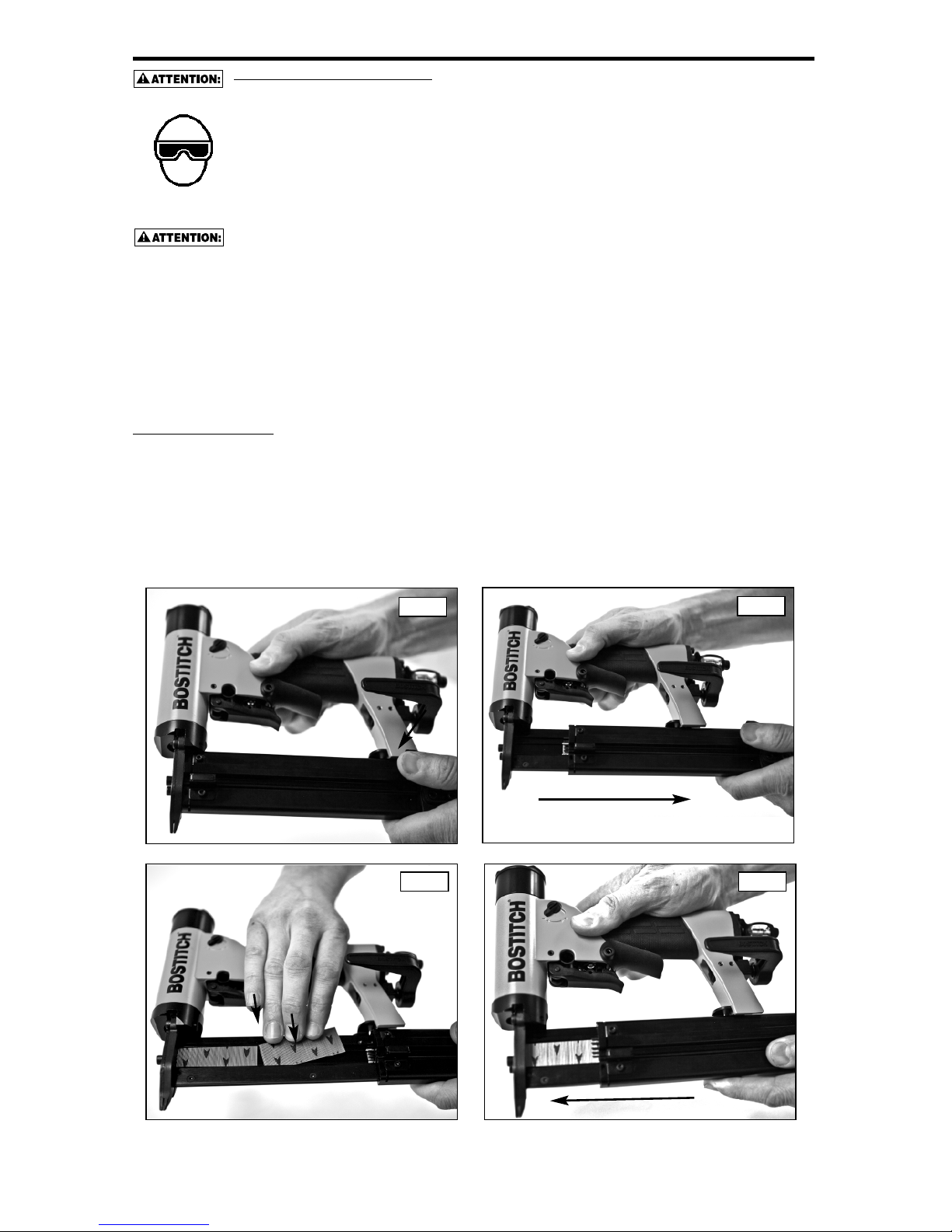
-30-
CHARGEMENT DU HP118K
UNE PROTECTION DES YEUX, conforme aux normes ANSI et fournissant une protection
contre les projectiles en provenance de l’AVANT et des CÔTÉS, doit toujours être portée par
l’opérateur et les personnes présentes dans la zone de travail, lors du raccordement au
r
éseau d’air, du chargement, du fonctionnement et de la maintenance de l’outil. Une telle
p
rotection est indispensable pour vous protéger contre les projections d’attaches et de
p
articules qui peuvent entraîner des blessures graves.
L
’employeur et/ou l’utilisateur doivent s’assurer du port d’une protection oculaire adéquate.
L’équipement de protection oculaire doit être conforme aux normes ANSI Z87.1 (de l’Institut
National Américain des Normes), et offrir une protection à la fois frontale et latérale.
REMARQUE : les lunettes de protection sans écrans latéraux et les masques de protection
portés seuls, n’offrent pas une protection suffisante.
POUR PRÉVENIR UN ACCIDENT
• Ne jamais placer la main ou toute autre partie du corps dans la zone d’éjection des clous
lorsque l’outil est relié à la source d’air.
• Ne jamais pointer le cloueur vers quelqu’un.
•
Ne jamais jouer avec l’outil.
• N'appuyez jamais sur la gâchette et ne la saisissez jamais sans que le nez de pose ne
soit dirigé vers la surface de travail.
• Toujours manier l’outil avec précautions.
• N’appuyez jamais sur aucune des deux gâchettes en chargeant l’outil.
CHARGEMENT :
1. Enfoncez le levier commandé par ressort, tel qu’illustré à la Figure 1.
2. Tirez la section coulissante du magasin vers l’arrière, tel qu’illustré à la Figure 2.
3. Chargez la barrette de goupilles, tel qu’illustré à la Figure 3, la flèche pointant vers le bas. Si les goupilles
présentent des points noirs au lieu de flèches, ces points doivent être orientés vers le haut.
4. Fermez le magasin (voir Fig. 4) de façon qu’il se verrouille en position avant. L’outil est maintenant prêt
à l’emploi.
Fig.1
Fig.2
Fig.3
Fig.4
Page 31

-31-
FONCTIONNEMENT DE L’APPAREIL
U
NE PROTECTION DES YEUX,conforme aux normes ANSI et fournissant une protection
c
ontre les projectiles en provenance de l’AVANT et des CÔTÉS, doit toujours être portée par
l’opérateur et les personnes présentes dans la zone de travail, lors du raccordement au
réseau d’air, du chargement, du fonctionnement et de la maintenance de l’outil. Une telle
protection est indispensable pour vous protéger contre les projections d’attaches et de
p
articules qui peuvent entraîner des blessures graves.
L’employeur et/ou l’utilisateur doivent s’assurer du port d’une protection oculaire adéquate.
L
’équipement de protection oculaire doit être conforme aux normes ANSI Z87.1 (de l’Institut
N
ational Américain des Normes), et offrir une protection à la fois frontale et latérale.
REMARQUE : les lunettes de protection sans écrans latéraux et les masques de protection
p
ortés seuls, n’offrent pas une protection suffisante.
AVANT DE MANIPULER OU D’UTILISER CET OUTIL :
I
. LIRE ET COMPRENDRE LES AVERTISSEMENTS CONTENUS DANS CE MANUEL.
BOSTITCH permet un type de fonctionnement pour la série d’outils HP118K.
FONCTIONNEMENT DE LA GÂCHETTE AVEC LA GÂCHETTE SECONDAIRE
FONCTIONNEMENT
FONCTIONNEMENT DE LA GÂCHETTE AVEC LA GÂCHETTE SECONDAIRE :
L’outil sera actionné chaque fois que la gâchette sous la soupape est appuyée jusqu’à ce que la gâchette
secondaire sous la poignée de main soit relâchée. Cet outil à gâchette est actionné en appuyant sur ou en
saisissant d'abord la gâchette secondaire sous la poignée de main, puis en appuyant sur la gâchette sous la
soupape, tel qu’indiqué.
N'appuyez jamais sur la gâchette et ne la saisissez jamais par inadvertance alors que vous
bougez, changez de lieu de travail, lorsque vous rangez l’outil dans son étui ou l’accrochez
pour le suspendre ou lorsque vous préparez une surface de travail pour une opération de
pose d’attaches.
L’opérateur ne doit pas maintenir la gâchette secondaire enfoncée sauf lors des opérations
de pose d'attaches puisque de graves blessures peuvent être causées si la gâchette entrait
accidentellement en contact avec quelqu'un ou quelque chose, ce qui pourrait actionner
l'outil.
Appuyez sur ou saisissez cette
gâchette secondaire d’abord
Appuyez sur cette gâchette en deuxième
Page 32

-32-
UTILISATION DU CROCHET DE CEINTURE
D
ébranchez toujours l’outil de l’alimentation d’air avant de procéder à des réglages ou
d
'effectuer des réparations.
L’opérateur ne doit pas maintenir la gâchette secondaire enfoncée sauf lors des opérations
de pose d'attaches puisque de graves blessures peuvent être causées si la gâchette entrait
accidentellement en contact avec quelqu'un ou quelque chose, ce qui pourrait actionner
l'outil.
N'appuyez jamais sur la gâchette et ne la saisissez jamais par inadvertance alors que vous
bougez, changez de lieu de travail, lorsque vous rangez l’outil dans son étui ou l’accrochez
pour le suspendre ou lorsque vous préparez une surface de travail pour une opération de
pose d’attaches.
FONCTIONNEMENT ET ORIENTATION :
Le crochet de ceinture peut être réglé sur l’une de deux orientations; ouvert ou fermé. L’orientation « ouvert
» permet à l’utilisateur de suspendre l'outil d'une ceinture (ou l'équivalent) alors que la position « fermé »
permet à l’utilisateur de replacer l’outil dans le coffre. Ce qui suit décrit ces deux orientations :
Pour régler l’outil sur l’une ou l’autre de ces deux orientations, appuyez simplement vers le bas sur le
crochet à chevron, faites-le tourner dans le sens des aiguilles d’une montre ou dans le sens inverse des
aiguilles d’une montre et relâchez-le, tel qu'illustré à la Fig 1
1. POUSSEZ VERS LE BAS SUR
LE CROCHET À CHEVRON
2.FAITES
TOURNER
3. RELÂCHEZ
Fig.1
OVERT
FERMÉ
Page 33
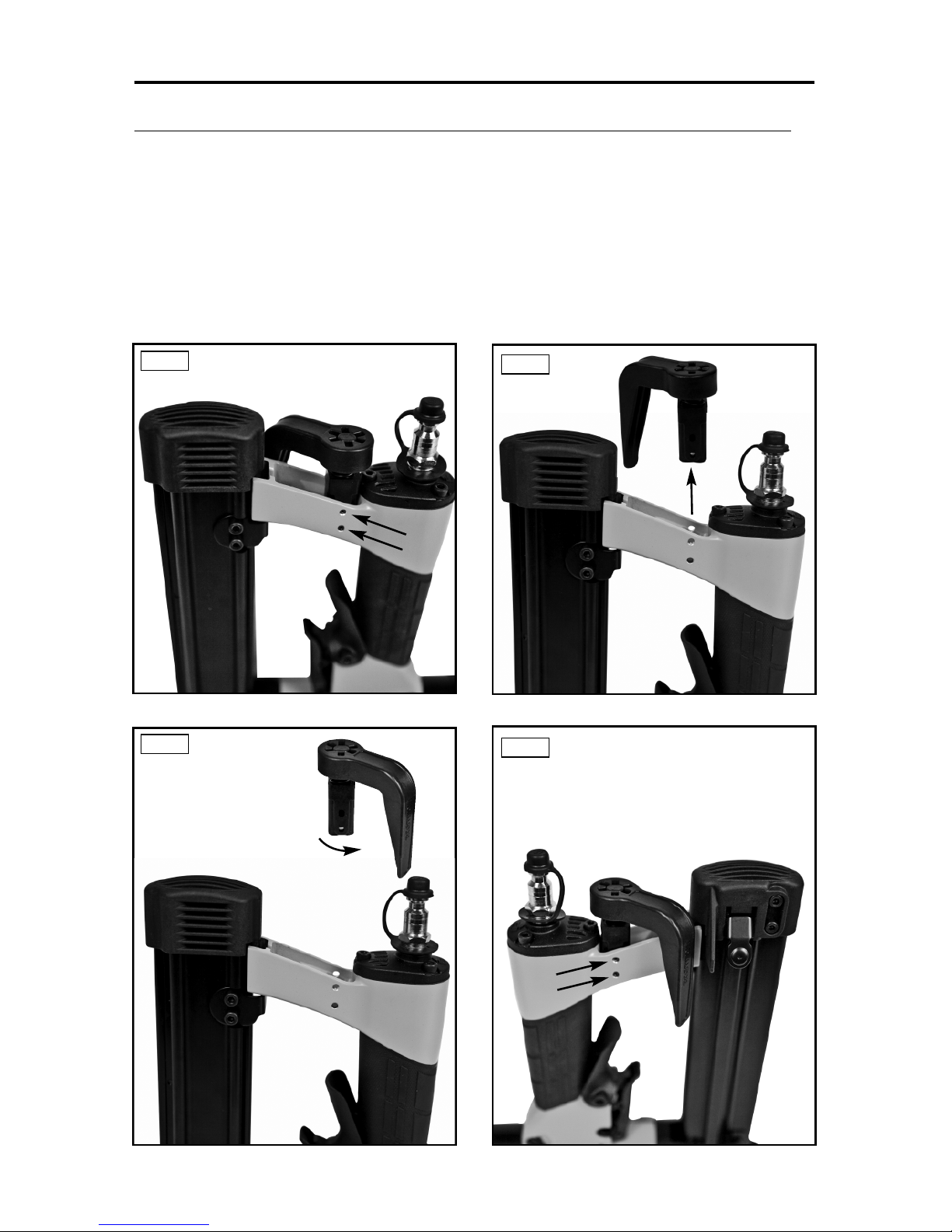
-33-
UTILISATION DU CROCHET DE CEINTURE
RÉGLAGE DU CROCHET DE CEINTURE POUR LES UTILISATEURS GAUCHERS :
Afin de régler l’outil pour un utilisateur gaucher, retirez simplement l’ensemble crochet de ceinture, faites-le
t
ourner de 180° et réinstallez-le. Ce qui suit décrit exactement ce processus :
1
. Enlevez les deux goupilles élastiques qui fixent l’ensemble crochet de ceinture au cadre, tel
qu’illustré à la Fig 1.
2. Faites glisser l’ensemble crochet de ceinture dans la direction opposée de l’arrière de l’outil,
t
el qu’illustré à la Fig 2.
3. Faites tourner l’ensemble crochet de ceinture de 180°, tel qu’illustré à la Fig 3.
4. Placez les trous du cadre vis-à-vis les trous dans le support. Ensuite, réinstallez les deux
g
oupilles élastiques, tel qu’illustré à la Fig 4.
Fig.1
Fig.2
Fig.3
Fig.4
Page 34

-34-
ÉLIMINATION D’ATTACHES COINCÉES
TOUJOURS COUPER L’ALIMENTATION EN AIR AVANT DE DÉBLOQUER UNE ATTACHE
COINCÉE.
DÉBLOCAGE D’UNE ATTACHE COINCÉE :
1
. Dégagez le magasin puis tirez-le vers l’arrière pour couper l’alimentation en goupilles.
2
. Desserrez les deux vis d’un tour complet, tel qu’illustré à la Fig. 1.
3
. Glissez le couvercle vers le bas, jusqu’à ce que les deux gros trous de passage s’alignent avec les deux
têtes de vis, tel qu’illustré à la Fig. 2.
4. Éloignez en tirant le couvercle du nez, tel qu’illustré à la Figure 3.
5. Retirez l’attache coincée.
6. Remettez le couvercle en place, faites-le glisser, serrez les deux vis puis refermez le magasin.
7
. Reconnectez le tuyau à air.
Fig.3Fig.2
Fig.1
RÉGLAGE DE LA PUISSANCE
Pour une puissance maximale : faites tourner le levier vers la droite, tel qu’illustré à la Fig. 1
Pour réduire la puissance : faites tourner le levier vers la gauche, tel qu’illustré à la Fig. 2
RÉGLAGE DE PUISSANCE MAXIMALE
RÉGLAGE DE PUISSANCE MINIMALE
Fig.1
Fig.2
Page 35

-35-
VÉRIFICATION DU SYSTÈME DE DÉCLENCHEMENT :
A
TTENTION : retirer toutes les attaches de fixation de l’outil avant de procéder à une vérification du
fonctionnement de celui-ci.
FONCTIONNEMENT DE LA GÂCHETTE AVEC LA GÂCHETTE SECONDAIRE :
La gâchette principale est située sous la soupape de la gâchette. Elle ne peut qu’actionner l’outil seulement
s
i la gâchette secondaire est déjà enfoncée.
L
a gâchette secondaire est située sous la poignée. La gâchette secondaire empêche la gâchette principale
d’actionner l’outil si la gâchette secondaire n’a pas été enfoncée au préalable.
P
lacez le nez de pose de l’outil contre la surface de travail pour toutes les vérifications d’utilisation suivantes.
A
. La main sur l’extrémité arrière de la poignée, loin de la gâchette secondaire, et n’appuyant pas sur
c
ette même gâchette, enfoncez la gâchette principale avec votre doigt.
L
’OUTIL NE DOIT PAS EFFECTUER UN CYCLE.
B
. La main sur la poignée, et tout en enfonçant la gâchette secondaire, enfoncez la gâchette principale
a
vec votre doigt.
L’OUTIL DOIT EFFECTUER UN CYCLE.
ATTENTION
: LORSQUE LA GÂCHETTE SECONDAIRE RESTE ENFONCÉE, L’OUTIL EFFECTUE UN
CYCLE À CHAQUE FOIS QUE LA GÂCHETTE PRINCIPALE EST ENFONCÉE!
EN SUPPLÉMENT DES AUTRES AVERTISSEMENTS CONTENUS DANS CE MANUEL,
OBSERVEZ LES RÈGLES SUIVANTES POUR OPÉRER EN TOUTE SÉCURITÉ
• Utiliser cet outil pneumatique BOSTITCH uniquement pour éjecter des éléments d’assemblage.
• Ne jamais utiliser l’outil de telle manière qu’un élément d’assemblage peut être dirigé vers vousmême ou vers d’autres personnes présentes dans la zone de travail.
• Ne pas utiliser l’outil comme un marteau
• Porter toujours l’outil par la poignée, jamais par le nez.
• Ne pas altérer ou modifier cet outil par rapport à sa forme originale sans l’agrément de BOSTITCH.
• Toujours avoir présent à l’esprit qu’une manipulation ou une utilisation inadéquate de cet outil
peuvent causer des blessures.
• Ne jamais attacher ou maintenir la détente en position déchenchée.
• Ne jamais laisser le cloueur connecté au tuyau d’air sans surveillance.
• Ne pas utiliser cet outil s’il n’est pas pourvu d’une ÉTIQUETTE D’AVERTISSEMENT (WARNING
LABEL) lisible.
• Cesser d’utiliser un outil qui perd de l’air ou ne fonctionne pas correctement. Notifier votre
concessionnaire BOSTITCH si votre outil continue à mal fonctionner.
GÂCHETTE SECONDAIRE
GÂCHETTE PRINCIPALE
Page 36

-36-
PROBLÈMES DE FONCTIONNEMENT
PROBLÈME CAUSE CORRECTION
F
uite d’air au corps de valve de détente. Joints toriques coupés ou usés. . . . . . . . . . . . . . Remplacer les joints toriques .
Fuite d’air à la tige de valve de détente. Joints toriques ou garnitures coupés ou usés. . . Remplacer joints toriques garnitures.
Fuite d’air entre le corps et le nez. Vis du nez desserrées. . . . . . . . . . . . . . . . . . . . . Resserrer les vis
R
emplacer les joints toriques.. . . . . . . . . . . . . . . Joints toriques ou garniture coupés ou usés.
Remplacer l’amortisseur . . . . . . . . . . . . . . . . . . . Amortisseur coupé ou usé.
F
uite d’air entre le chapeau et le corps. Garniture coupée. . . . . . . . . . . . . . . . . . . . . . . . . Remplacer la garniture.
A
mortisseur de tête coupé ou usé.. . . . . . . . . . . Remplacer l’amortisseur.
V
is de chapeau desserrées. . . . . . . . . . . . . . . . . Resserrer les vis.
C
ycle incomplet Pertes de charges dans le circuit d’air. . . . . . . . Vérifier le circuit d’air
A
ppareil sec, absence de lubrification. . . . . . . . . Utiliser un lubrifiant BOSTITCH
Joints toriques de la valve de tête . . . . . . . . . . . Remplacer les joints toriques.
coupés ou usés.
Ressort du chapeau de cylindre cassé. . . . . . . . Remplacer le ressort
Valve de tête forcée dans le chapeau. . . . . . . . . Démonter (vérifier) lubrifier.
Perte de puissance Appareil sec, absence de lubrification. . . . . . . . . Utiliser un lubrifiant BOSTITCH
Fonctionnement ralenti Ressort du chapeau de cylindre cassé. . . . . . . . Remplacer le ressort.
Joints toriques ou garnitures coupés ou usés. . . Remplacer les joints toriques/garnitures.
Échappement bloqué . . . . . . . . . . . . . . . . . . . . . Vérifier l’amortisseur et le ressort de
. . . . . . . . . . . . . . . . . . . . . . . . . . . . . . . . . . . . . . valve de ête.
Système détente usé ou ayant une fuite. . . . . . . Remplacer le système de détente.
Particules obstruant le canal de l’enfonceur. . . . Démonter le nez/enfonceur et nettoyer.
L’extrémité du cylindre n’est pas positionnée . . . Démonter et réinstaller.
c
orrectement sur l’amortisseur inférieur.
V
alve de tête sèche. . . . . . . . . . . . . . . . . . . . . . . Démonter et lubrifier
P
ression d’air trop faible.. . . . . . . . . . . . . . . . . . . Vérifier le circuit d’air.
É
léments d’assemblage manquants Amortisseur usé. . . . . . . . . . . . . . . . . . . . . . . . . . Remplacer l’amortisseur.
A
limentation Intermittente Particules obstruant le canal de l’enfonceur. . . . Démonter le nez/enfonceur et nettoyer.
Pertes de charges dans les raccords rapides . . Remplacer les raccords rapides du circuit.
. . . . . . . . . . . . . . . . . . . . . . . . . . . . . . . . . . . . . . du circuit d’air.
Joint du piston usé. . . . . . . . . . . . . . . . . . . . . . . . Remplacer le joint, vérifier l’enfonceur.
Appareil sec, absence de lubrification. . . . . . . . . Utiliser un lubrifiant BOSTITCH
Ressort du poussoir endommagé. . . . . . . . . . . . Remplacer le ressort.
Pression d’air trop faible.. . . . . . . . . . . . . . . . . . . Vérifier le circuit/régler la pression d’air.
Vis du magasin desserrées. . . . . . . . . . . . . . . . . Resserrer les vis.
Éléments d’assemblage trop courts . . . . . . . . . . Utiliser les éléments d’assemblage
. . . . . . . . . . . . . . . . . . . . . . . . . . . . . . . . . . . . . . recommandés.
Éléments d’assemblage tordus . . . . . . . . . . . . . . Cesser l’utilisation de ces éléments
Taille incorrecte des éléments d’assemblage . . . Utiliser les éléments d’assemblage
. . . . . . . . . . . . . . . . . . . . . . . . . . . . . . . . . . . . . . recommandés.
Fuite à la garniture du chapeau de tête.. . . . . . . Resserrer les vis/remplacer la garniture.
Joints toriques de la valve de détente coupés . . Remplacer les joints toriques.
ou usés.
Enfonceur usé ou cassé. . . . . . . . . . . . . . . . . . . Remplacer l’enfonceur/vérifier le joint de
. . . . . . . . . . . . . . . . . . . . . . . . . . . . . . . . . . . . . . piston.
Magasin sec ou encrassé. . . . . . . . . . . . . . . . . . Nettoyer et lubrifier le magasin avec un
. . . . . . . . . . . . . . . . . . . . . . . . . . . . . . . . . . . . . . lubrifiant BOSTITCH
Magasin usé.. . . . . . . . . . . . . . . . . . . . . . . . . . . . Remplacer le magasin
Les éléments d’assemblage se coincent Canal de l’enfonceur usé. . . . . . . . . . . . . . . . . . . Remplacer le nez/vérifier la porte.
dans l’appareil Taille incorrecte des éléments d’assemblage. . . Utiliser les éléments d’assemblage
. . . . . . . . . . . . . . . . . . . . . . . . . . . . . . . . . . . . . . recommandés.
Éléments d’assemblage tordus . . . . . . . . . . . . . . Cesser d’utiliser ces éléments
Vis du nez/magasin desserrées. . . . . . . . . . . . . . Resserrer les vis.
Enfonceur usé ou cassé. . . . . . . . . . . . . . . . . . . Remplacer l’enfonceur.
Page 37

-37-
ENTRETIEN DE L’APPAREIL
L
ors de l’utilisation d’un outil fonctionnant sous-pression, lire les avertissements du manuel
e
t user d’extrêmes précautions lors de la découverte d’un problème.
PIÈCES DE RECHANGE :
I
l est recommandé d’utiliser uniquement les pièces de rechange BOSTITCH. Ne pas utiliser de pièces
modifiées, ou autres pièces dont les performances ne seraient pas équivalentes aux pièces d’origine.
PROCÉDURE D’ASSEMBLAGE DES GARNITURES :
Lors des réparations, vérifier que les pièces internes sont propres et bien lubrifiées. Appliquer du lubrifiant “O”
LUBE de Parker sur tous les joints toriques, avant de procéder à l’assemblage.Appliquer une fine pellicule de “O”
L
UBE sur toutes les pièces mobiles et pivots. Les opérations de remontage terminées, veiller à mettre quelques
gouttes de lubrifiant pour outils pneumatiques BOSTITCH dans le circuit d’air avant de procéder aux essais.
ALIMENTATION D’AIR - PRESSION - VOLUME :
Le volume d’air est aussi important que la pression. Le volume d’air nécessaire au bon fonctionnement de
l
’appareil peut être perturbé par des tuyaux et des raccordements sous dimensionnés, ou par la présence d’eau
dans le circuit d’air. Même si la pression d’air lue au manomètre est correcte, les diminutions du volume d’air se
traduiront par une perte de puissance de l’appareil, une diminution de la vitesse ou une alimentation inadéquate.
Avant de rechercher la cause de ces symptômes, vérifier les raccords et les tuyaux depuis l’outil jusqu’à la source
d’énergie et vérifier qu’il n’existe pas de raccords trop serrés, tordus, des niveaux bas contenant de l’eau, ou tout
autre cause qui puisse expliquer une diminution du volume d’air vers l’appareil.
DÉMONTAGE DE LA SOUPAPE DE GÂCHETTE :
1. Retirez les deux goupilles de la soupape de gâchette ainsi que la gâchette secondaire et son ressort.
2. Retirez la soupape de gâchette (la gâchette principale y étant toujours fixée).
Goupille
de la soupape
de gâchette
Soupape de
gâchette et
gâchette principale
Goupille de
la soupape
de gâchette
Le ressort est situé sous la
gâchette secondaire
Gâchette secondaire
ACCESSOIRES DISPONIBLES
BC601 Lubrifiant pour outil pneumatique BOSTITCH 124 g (4 oz)
BC602 Lubrifiant pour outil pneumatique BOSTITCH 473 ml (1 chopine)
BC603 Lubrifiant pour outil pneumatique (formule hivernale) BOSTITCH 473 ml
(1 chopine)
BC604 Lubrifiant pour outil pneumatique BOSTITCH 946 ml (1 pinte)
100679 Lubrifiant pour joint torique 454 g (1 lb)
851325 Loctite Grade 271 0,57 ml (0,02 oz)
851385 Loctite Grade 242 0,57 ml (0,02 oz)
Page 38

-38-
NOTES
Page 39

-39-
NOTES
 Loading...